EP2865930B1 - Flanschverbindungsstruktur - Google Patents
Flanschverbindungsstruktur Download PDFInfo
- Publication number
- EP2865930B1 EP2865930B1 EP14195800.9A EP14195800A EP2865930B1 EP 2865930 B1 EP2865930 B1 EP 2865930B1 EP 14195800 A EP14195800 A EP 14195800A EP 2865930 B1 EP2865930 B1 EP 2865930B1
- Authority
- EP
- European Patent Office
- Prior art keywords
- flange
- sealing liquid
- pouring
- flanges
- connection structure
- Prior art date
- Legal status (The legal status is an assumption and is not a legal conclusion. Google has not performed a legal analysis and makes no representation as to the accuracy of the status listed.)
- Active
Links
- 239000007788 liquid Substances 0.000 claims description 160
- 238000007789 sealing Methods 0.000 claims description 156
- 230000005856 abnormality Effects 0.000 claims description 34
- 239000012530 fluid Substances 0.000 claims description 23
- 238000004891 communication Methods 0.000 claims description 12
- 238000001514 detection method Methods 0.000 claims description 10
- 238000007599 discharging Methods 0.000 claims description 3
- 230000008878 coupling Effects 0.000 claims description 2
- 238000010168 coupling process Methods 0.000 claims description 2
- 238000005859 coupling reaction Methods 0.000 claims description 2
- 239000007789 gas Substances 0.000 description 102
- 230000002093 peripheral effect Effects 0.000 description 34
- 230000003247 decreasing effect Effects 0.000 description 11
- UFHFLCQGNIYNRP-UHFFFAOYSA-N Hydrogen Chemical compound [H][H] UFHFLCQGNIYNRP-UHFFFAOYSA-N 0.000 description 4
- 238000004140 cleaning Methods 0.000 description 4
- 238000006073 displacement reaction Methods 0.000 description 4
- 238000007689 inspection Methods 0.000 description 4
- XLYOFNOQVPJJNP-UHFFFAOYSA-N water Substances O XLYOFNOQVPJJNP-UHFFFAOYSA-N 0.000 description 4
- 230000005484 gravity Effects 0.000 description 2
- 238000012423 maintenance Methods 0.000 description 2
- 230000005514 two-phase flow Effects 0.000 description 2
- 230000001419 dependent effect Effects 0.000 description 1
- 230000000694 effects Effects 0.000 description 1
- 238000005516 engineering process Methods 0.000 description 1
- 239000002360 explosive Substances 0.000 description 1
- 238000011010 flushing procedure Methods 0.000 description 1
- 231100001261 hazardous Toxicity 0.000 description 1
- 230000013011 mating Effects 0.000 description 1
- 239000000203 mixture Substances 0.000 description 1
- 239000000126 substance Substances 0.000 description 1
- 238000003466 welding Methods 0.000 description 1
Images


Classifications
-
- F—MECHANICAL ENGINEERING; LIGHTING; HEATING; WEAPONS; BLASTING
- F16—ENGINEERING ELEMENTS AND UNITS; GENERAL MEASURES FOR PRODUCING AND MAINTAINING EFFECTIVE FUNCTIONING OF MACHINES OR INSTALLATIONS; THERMAL INSULATION IN GENERAL
- F16L—PIPES; JOINTS OR FITTINGS FOR PIPES; SUPPORTS FOR PIPES, CABLES OR PROTECTIVE TUBING; MEANS FOR THERMAL INSULATION IN GENERAL
- F16L23/00—Flanged joints
- F16L23/16—Flanged joints characterised by the sealing means
- F16L23/167—Flanged joints characterised by the sealing means in connection with the appearance or detection of leaks
-
- F—MECHANICAL ENGINEERING; LIGHTING; HEATING; WEAPONS; BLASTING
- F16—ENGINEERING ELEMENTS AND UNITS; GENERAL MEASURES FOR PRODUCING AND MAINTAINING EFFECTIVE FUNCTIONING OF MACHINES OR INSTALLATIONS; THERMAL INSULATION IN GENERAL
- F16L—PIPES; JOINTS OR FITTINGS FOR PIPES; SUPPORTS FOR PIPES, CABLES OR PROTECTIVE TUBING; MEANS FOR THERMAL INSULATION IN GENERAL
- F16L2201/00—Special arrangements for pipe couplings
- F16L2201/30—Detecting leaks
Definitions
- This invention relates to a flange connection structure, which is designed to improve sealing properties by utilizing a sealing liquid in a case such as a case where pipes or the like are connected by flanges, or a case where a manhole of a tank and a cover are connected by flanges.
- the present invention is designed to improve sealing properties against a fluid, especially, a fluid containing a gas.
- a thermal power plant or a chemical plant many pipes are routed and arranged, and many tanks are installed.
- one of the pipes and another of the pipes may be connected by flanges for convenience in connecting the pipes.
- a manhole of a tank and a cover for closing the manhole may be connected by flanges.
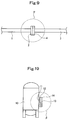
- Fig. 9 shows a conventional flange connection structure to be applied to piping or a pipe.
- a flange 2 is formed on one pipe 1
- a flange 4 is formed on another pipe 3.
- a gasket is interposed between a flange surface of the flange 2 and a flange surface of the flange 4, and the flanges 2 and 4 are fastened by bolts (not shown), whereby the flange surface of the flange 2 and the flange surface of the flange 4 are joined together.
- the pipe 1 and the pipe 4 are coupled together.
- Fig. 10 shows a conventional flange connection structure to be applied to a tank.
- a flange 12 is formed on a manhole 11 of a tank 10
- a flange 14 is formed on a cover 13.
- a gasket is interposed between a flange surface of the flange 12 and a flange surface of the flange 14, and the flanges 12 and 14 are fastened by bolts (not shown), whereby the flange surface of the flange 12 and the flange surface of the flange 14 are joined together.
- the manhole 11 is closed by the cover 13.
- the manhole 11 is closed with the cover 13 according to such a flange connection structure, it suffices to loosen and detach the bolts fastening the flanges 12 and 14, when allowing access to the interior of the tank 10 for maintenance, inspection or cleaning. By this measure, the tank 10 can be opened. In restoring the tank to the original state, it is enough to perform the simple work of fastening the flanges 12 and 14 by the bolts.
- JP 2001-289331A discloses a seal mechanism capable of preventing a contact of an explosive gas or an ignitable gas with atmospheric air.
- FR 1341382A discloses a flange connection structure including two flanges coupled at their flange surfaces and fastened by bolts.
- the flange connection structure comprises an annular cavity formed in the flange surface of one of the flanges.
- a pouring passage is formed in the same flange and is suitable to bring the cavity and an axial outer surface of the same flange into communication with each other.
- a discharge passage is formed in the same flange and is suitable to bring the cavity and the axial outer surface of the same flange into communication with each other.
- a valve is provided in a first pipe that is connected to the pouring passage at the axial surface for introducing a sealing liquid into the cavity, and a second pipe is connected to the discharge passage at the axial surface for removing a sealing liquid from the cavity.
- a diaphragm is arranged within both pipes and the purpose of the diaphragms is to maintain a pressure within the cavity above atmospheric pressure.
- DE 4130593A1 discloses a flange connection structure including two flanges coupled at their flange surfaces and fastened by clamping conical radial outer ends of the flanges together by means of a clamping piece such that the outer circumferential surfaces of the flanges are surrounded and covered by the clamping piece.
- the flange connection structure comprises an annular recess formed in the mating flange surfaces of both flanges between two radially spaced apart O-ring gaskets.
- a passage connecting the axial end face of each flange with the recess is formed in both flanges. These passages are provided for flushing the recess with a fluid or gas in order to disinfect it or to create an inert environment within the recess for increased safety operations.
- a flange connection structure for a pipe, and a flange connection structure for the manhole of a tank have been considered to be sealing structures capable of complete sealing.
- a region ⁇ surrounding the flange connection structure shown in Fig. 9 is designated as an explosion-proof range (i.e., hazardous area), or a region ⁇ surrounding the flange connection structure shown in Fig. 10 is designated as an explosion-proof range.
- an instrument or a gauge which becomes an ignition source, has not been installed, or an instrument or gauge of a special design has been used. So doing, however, has posed the problem that the design of the plant in limited in the degree of freedom and is costly.
- the present invention has been accomplished in the light of the above-described conventional technologies. It is an object of the present invention to provide a flange connection structure, such as a flange connection structure for coupling pipes together, a connection structure for tanks or instruments, or a flange connection structure for closing a manhole of a tank with a cover, the flange connection structure having enhanced sealing properties.
- a flange connection structure such as a flange connection structure for coupling pipes together, a connection structure for tanks or instruments, or a flange connection structure for closing a manhole of a tank with a cover, the flange connection structure having enhanced sealing properties.
- the present invention provides a flange connection structure with the features of claim 1.
- Preferred embodiments are defined in the dependent claims..
- the present invention provides a flange connection structure including a flange formed in a pipe for flowing a fluid therethrough, and a flange formed in another pipe for flowing the fluid therethrough, the flanges being fastened by bolts, whereby flange surfaces of the flanges are joined together to couple the pipes together, or a flange connection structure including a flange formed in a manhole of a tank for storing a fluid and a flange formed in a cover, the flanges being fastened by bolts, whereby flange surfaces of the flanges are joined together to close the manhole with the cover, or a flange connection structure including a flange formed in a pipe and a flange formed in a cover, the flanges being fastened by bolts, whereby flange surfaces of the flanges are joined together to close the pipe with the cover.
- the present invention preferably provides that a pouring pressure of the sealing liquid poured in by the sealing liquid pouring means is set to be lower than a fluid pressure of the fluid.
- the present invention preferably provides that the sealing liquid pouring means is equipped with pressure detection means for detecting a pressure of the sealing liquid poured into the pouring passage, or flow rate detection means for detecting a flow rate of the sealing liquid poured into the pouring passage, and that the flange connection structure further comprises abnormality determination means which determines that an abnormality occurred in joining of the flanges if there was a sharp decrease in the pressure detected by the pressure detection means, or if there was a sharp increase in the flow rate detected by the flow rate detection means.
- the incidence of leaks from the flange connection structure can be dramatically decreased. Consequently, the surroundings of the flange connection structure need not be designated as the explosion-proof range, and the degree of freedom to design the pipes, etc. can be raised. Since the flange connection structure can be adopted, moreover, overhaul inspection and cleaning can be performed easily.
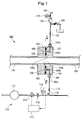
- Fig. 1 shows a flange connection structure 100 for a pipe according to Embodiment 1 of the present invention.
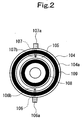
- Fig. 2 is a view taken along the arrowed line II-II in Fig. 1 .
- a flange 102 is formed on one pipe 101, and a flange 104 is formed on another pipe 103.
- the flanges 102 and 104 are fastened by bolts (not shown), whereby a flange surface 102a of the flange 102 and a flange surface 104a of the flange 104 are joined together. By so doing, the pipe 101 and the pipe 103 are coupled together.
- a combustible gas for example, a hydrogen gas
- a combustible gas having a positive pressure as its gas pressure
- An annular seal groove 105 is formed in the flange surface 104a of the flange 104. This seal groove 105 is formed on the outer peripheral side of the inner peripheral edge of the flange 104 and in such a state as to surround the inner peripheral surface of the flange 104.
- a pouring passage 106 and a discharge passage 107 are formed in the flange 104.
- the pouring passage 106 and the discharge passage 107 are formed to be offset by 180° .
- the pouring passage 106 is disposed on the lower side, and the discharge passage 107 is disposed on the upper side.
- the pouring passage 106 has one end 106a opening at the circumferential surface of the outer surface of the flange 104, and has the other end 106b opening in the seal groove 105, thereby bringing the seal groove 105 and the circumferential surface of the flange into communication with each other.
- the pouring passage 106 extends from the one end 106a in a nearly vertically upward direction, then bends in the horizontal direction, and reaches to the other end 106b.
- the discharge passage 107 has one end 107a opening at the circumferential surface of the outer peripheral surface of the flange 104, and has the other end 107b opening in the seal groove 105, thereby bringing the seal groove 105 and the circumferential surface of the flange into communication with each other.
- the discharge passage 107 extends from the one end 107a in a nearly vertically downward direction, then bends in the horizontal direction, and reaches to the other end 107b.
- Annular gaskets 108, 109 are interposed between the flange surface 102a of the flange 102 and the flange surface 104a of the flange 104.
- the gasket 108 is disposed on the inner peripheral side of the seal groove 105, and the gasket 109 is disposed on the outer peripheral side of the seal groove 105.
- the annular gasket 108, seal groove 105, and gasket 109 are arranged just concentrically.
- a sealing liquid pouring section 110 has a sealing liquid pouring source 111 for ejecting a sealing liquid (for example, water or oil).
- An ejection port of the sealing liquid pouring source 111 and the one end 106a of the pouring passage 106 are connected by a pouring pipe 112.
- a control valve 113, an orifice 114, and a check valve 115 are interposed in the pouring pipe 112, and a pressure gauge 116 is mounted on the pouring pipe 112.
- the pouring pressure of the sealing liquid poured from the sealing liquid pouring section 110 into the seal groove 105 via the pouring pipe 112 and the pouring passage 106 is set to be lower than the gas pressure of the combustible gas flowing through the pipes 101 and 103.
- the pressure gauge 116 detects the pressure of the sealing liquid poured into the pouring passage 106, and sends the value of the detected pressure to an abnormality determination section 117.
- the abnormality determination section 117 determines that an abnormality occurred, if the value of the detected pressure rapidly decreased. In the event of the abnormality determination, the abnormality determination section 117 takes a safety measure, such as shutting off the flow of the fluid within the pipe 101, and closes the control valve 113.
- the sealing liquid is poured from the single sealing liquid pouring source 111 into the single flange connection structure 100.
- the pouring pipe 112 can be arranged so that the sealing liquid can be poured into a plurality of the flange connection structures arranged in the pipe system.
- a discharge device 120 is connected to the one end 107a of the discharge passage 107 via a discharge pipe 121.
- the discharge device 120 has a float mechanism and an exhaust valve.
- the discharge device 120 is structured in the following manner: When the sealing liquid is sent to the discharge device 120 via the discharge pipe 121, the sealing liquid is sealed in without being discharged to the outside. If a gas is contained in the sealing liquid, however, only this gas can be discharged to the outside.
- the gas discharged from the discharge device 120 is discharged to the atmosphere via an exhaust pipe 122.
- the position of this discharge is set in a safe place distant from the plant where the pipes 101 and 103 are laid.
- a gas sensor 123 is disposed on the exhaust pipe 122. This gas sensor 123 detects the type of the gas discharged via the exhaust pipe 122.
- a safety device 124 is connected to the discharge pipe 121 to discharge the sealing liquid to the outside if the pressure of the sealing liquid within the discharge pipe 121 rises abnormally.
- the sealing liquid is ejected and poured in from the sealing liquid pouring source 111 of the sealing liquid pouring section 110, the sealing liquid is pressure-fed into and charged into the pouring pipe 112, the pouring passage 106, the seal groove 105, the discharge passage 107, the discharge pipe 121, and the discharge device 120. On this occasion, air which has been placed in each pipe is discharged to the atmosphere via the discharge device 120.
- this sealing liquid inside the seal groove 105 constitutes a liquid seal structure.
- the positive pressure combustible gas flowing through the pipes 101, 103 is doubly sealed up by the gasket 108 on the inner peripheral side and the liquid seal structure comprising the sealing liquid charged into the seal groove 105.
- the incidence of leaks of the combustible gas can be dramatically decreased thanks to the above sealing.
- the explosion-proof range surrounding the flange connection structure 100 can be restricted to a minimum.
- the gasket 109 on the outer peripheral side performs the function of preventing the sealing liquid from leaking to the outside.
- the sealing liquid If the pressure of the sealing liquid is rendered lower than the gas pressure of the combustible gas flowing through the pipes 101, 103, the sealing liquid does not enter the pipes 101, 103, and the sealing liquid is preventing from mixing with the combustible gas.
- the combustible gas which has leaked into the seal groove 105 in this manner, floats upward, while flowing through the seal groove 105, the discharge passage 107 and the discharge pipe 121, owing to a difference in specific gravity between the combustible gas and the sealing liquid, and arrives at the discharge device 120.
- the discharge device 120 discharges only the combustible gas to the outside (into the atmosphere) via the exhaust pipe 122, without discharging the sealing liquid.
- the discharge position where the combustible gas is discharged to the atmosphere via the exhaust pipe 122 is in a safe place distant from the plant where the pipes 101, 103 are laid. Thus, discharge of the combustible gas has no problem.
- the gas sensor 123 can detect that the combustible gas has flowed through it. Upon detection of the flow-through movement of the combustible gas by the gas sensor 123, a safety measure, such as issuance of an alarm or the stoppage of passage of the combustible gas flowing through the pipes 101, 103, can be taken.
- the safety device 124 When the sealing liquid expands and its pressure becomes extremely high because of the heat of the combustible gas flowing through the pipes 101, 103 or the heat of an atmosphere surrounding the flanges, the safety device 124 is actuated to release the sealing liquid to the outside.
- the sealing liquid poured into the seal groove 105 flows out in a large amount, and the value of the detected pressure detected by the pressure gauge 116 is decreased sharply.
- the abnormality determination section 117 determines that an abnormality occurred, takes a safety measure, such as shutting off the flow of the fluid within the pipe 101, and closes the control valve 113. By these measures, a further outflow of the sealing liquid to the outside can be prevented.
- a flow meter may be installed instead of the pressure gauge 116. If the amount of the detected flow rate detected by the flow meter increased sharply, the abnormality determination section 117 may make a determination of abnormality and close the control valve 113.
- Embodiment 1 can be applied, unchanged, even in a case where a two-phase fluid having a gas and a liquid mixed is flowed through the pipes 101, 103.
- Fig. 3 shows a flange connection structure 100A for a pipe according to Example 1 serving to explain features of the present invention.
- Fig. 4 is a view taken along the arrowed line IV-IV in Fig. 3 .
- a combustible gas for example, a hydrogen gas
- a combustible gas having a positive pressure as its gas pressure
- An annular seal groove 105 is formed in a flange surface 104a of a flange 104. This seal groove 105 is formed on the outer peripheral side of the inner peripheral edge of the flange 104 and in such a state as to surround the inner peripheral surface of the flange 104.
- a pouring passage 106 and a discharge passage 107-1 are formed in the flange 104.
- the pouring passage 106 has one end 106a opening at the circumferential surface of the outer surface of the flange 104, and has the other end 106b opening in the seal groove 105, thereby bringing the seal groove 105 and the circumferential surface of the flange into communication with each other.
- the discharge passage 107-1 has one end 107-1a opening in a space on the inner peripheral side of the flange 104, and has the other end 107-1b opening in the seal groove 105, thereby bringing the seal groove 105 and the space on the inner peripheral side of the flange into communication with each other.
- Example 1 is different from Embodiment 1 in that the one end 107-1a of the discharge passage 107-1 is open in the space on the inner peripheral side of the flange 104.
- the one end 107-1a of the discharge passage 107-1 may be provided with a leakage restricting device 107-1c for restricting the leakage of the sealing liquid.
- An annular gasket 109 is interposed between a flange surface 102a of a flange 102 and the flange surface 104a of the flange 104.
- a sealing liquid pouring section 110 has a sealing liquid pouring source 111 for ejecting a sealing liquid (for example, water or oil), a pouring pipe 112, a control valve 113, an orifice 114, a check valve 115, a pressure gauge 116, and an abnormality determination section 117.
- a sealing liquid for example, water or oil
- the pouring pressure of the sealing liquid poured from the sealing liquid pouring section 110 into the seal groove 105 via the pouring pipe 112 and the pouring passage 106 is set to be higher than the gas pressure of the combustible gas flowing through the pipes 101 and 103.
- the pouring pressure of the sealing liquid is set to be lower than the gas pressure of the combustible gas flowing through the pipes 101 and 103.
- Example 1 is different from Embodiment 1 in that the pouring pressure of the sealing liquid is assumed to be rendered higher than the gas pressure of the combustible gas flowing through the pipes 101 and 103.
- the sealing liquid when the sealing liquid is ejected and poured in from the sealing liquid pouring source 111 of the sealing liquid pouring section 110, the sealing liquid is pressure-fed into and charged into the seal groove 105 via the pouring pipe 112 and the pouring passage 106. Moreover, the sealing liquid pressure-fed into and charged into the seal groove 105 is discharged into the pipe 103 via the discharge passage 107-1, and flowed through the pipe 103.
- the seal groove 105 is charged with the sealing liquid and, if the pressure of the sealing liquid, in particular, is rendered higher than the pressure of the fluid flowing in the pipes 101, 103, satisfactory sealing properties are obtained.
- the liquid leaking into the pipe 103 can also be adjusted by the leakage restricting device 107-1c.
- the liquid which has leaked is separated into the gas and the liquid by a suitable separator (not shown), and recovered.
- a suitable separator not shown
- this sealing liquid inside the seal groove 105 constitutes a liquid seal structure.
- the positive pressure combustible gas flowing through the pipes 101, 103 is reliably sealed up by the liquid seal structure comprising the high pressure sealing liquid charged into the seal groove 105.
- the incidence of leaks of the combustible gas can be dramatically decreased thanks to the above sealing.
- the explosion-proof range surrounding the flange connection structure 100A can be restricted to a minimum.
- the gasket 109 on the outer peripheral side performs the function of preventing the sealing liquid from leaking to the outside.
- sealing by the liquid seal structure comprising the sealing liquid charged into the seal groove 105 ensures a reliable seal. If displacement or a gap occurs in the flange connection surface for some cause, such as an accident, however, the sealing liquid in a larger amount than the normal amount may leak into the pipes 101, 103, whereas the combustible gas does not leak to the outside.
- the sealing liquid poured into the seal groove 105 flows out in a large amount, and the value of the detected pressure detected by the pressure gauge 116 is decreased sharply.
- the abnormality determination section 117 determines that an abnormality occurred, takes a safety measure, such as shutting off the flow of the fluid within the pipe 101, and closes the control valve 113. By these measures, a further outflow of the sealing liquid to the outside can be prevented.
- a flow meter may be installed instead of the pressure gauge 116. If the amount of the detected flow rate detected by the flow meter increased sharply, the abnormality determination section 117 may make a determination of abnormality and close the control valve 113.
- Example 1 can be applied as such even in a case where a two-phase fluid having a gas and a liquid mixed is flowed through the pipes 101, 103.
- Fig. 5 shows a flange connection structure 200 for a pipe end closing cover or a tank according to Embodiment 2 of the present invention.
- Fig. 6 is a view taken along the arrowed line VI-VI in Fig. 5 . Sections performing the same functions as those in Embodiment 1 will be described, with the same numerals as in Embodiment 1 being assigned thereto.
- a flange 202 is formed in a manhole 201 formed in a tank (not shown), and a flange 204 is formed in a cover 203.
- the flanges 202 and 204 are fastened by bolts (not shown), whereby a flange surface 202a of the flange 202 and a flange 204a of the flange 204 are joined together. By so doing, the manhole 201 is closed with the cover 203.
- the manhole 201 is closed with the cover 203, whereby a combustible gas (for example, a hydrogen gas), which has a positive pressure as its gas pressure and which is stored in the tank, is sealed in.
- a combustible gas for example, a hydrogen gas
- the cover 203 serves as a pipe end closing cover for closing the end of this pipe, and closes the end of the pipe.
- An annular seal groove 205 is formed in the flange surface 204a of the flange 204.
- This seal groove 205 on the side of the cover 203 is formed on the outer peripheral side of the inner peripheral edge of the flange 202 located on the side of the manhole 201 and in such a state as to surround the inner peripheral surface of the flange 202.
- a pouring passage 206 and a discharge passage 207 are formed in the flange 204.
- the pouring passage 206 and the discharge passage 207 are formed to be offset by 180°.
- the pouring passage 206 is disposed on the lower side, and the discharge passage 207 is disposed on the upper side.
- the pouring passage 206 has one end 206a opening at the circumferential surface of the outer surface of the flange 204, and has the other end 206b opening in the seal groove 205, thereby bringing the seal groove 205 and the circumferential surface of the flange into communication with each other.
- the pouring passage 206 extends from the one end 206a in a nearly vertically upward direction, then bends in the horizontal direction, and reaches to the other end 206b.
- the discharge passage 207 has one end 207a opening at the circumferential surface of the outer peripheral surface of the flange 204, and has the other end 207b opening in the seal groove 205, thereby bringing the seal groove 205 and the circumferential surface of the flange into communication with each other.
- the discharge passage 207 extends from the one end 207a in a nearly vertically downward direction, then bends in the horizontal direction, and reaches to the other end 207b.
- Annular gaskets 208, 209 are interposed between the flange surface 202a of the flange 202 and the flange surface 204a of the flange 204.
- the gasket 208 is disposed on the inner peripheral side of the seal groove 205, and the gasket 209 is disposed on the outer peripheral side of the seal groove 205.
- the annular gasket 208, seal groove 205, and gasket 209 are arranged just concentrically.
- a sealing liquid pouring section 110 has a sealing liquid pouring source 111 for ejecting a sealing liquid (for example, water or oil).
- An ejection port of the sealing liquid pouring source 111 and the one end 206a of the pouring passage 206 are connected by a pouring pipe 112.
- a control valve 113, an orifice 114, and a check valve 115 are interposed in the pouring pipe 112, and a pressure gauge 116 is mounted on the pouring pipe 112.
- the pouring pressure of the sealing liquid poured from the sealing liquid pouring section 110 into the seal groove 205 via the pouring pipe 112 and the pouring passage 206 is set to be lower than the gas pressure of the combustible gas in the tank.
- the pressure gauge 116 detects the pressure of the sealing liquid poured into the pouring passage 206, and sends the value of the detected pressure to an abnormality determination section 117.
- the abnormality determination section 117 detects that an abnormality occurred, if the value of the detected pressure rapidly decreased. In the event of the abnormality determination, the abnormality determination section 117 takes a safety measure, such as issuing an alarm, and closes the control valve 113.
- a discharge device 120 is connected to the one end 207a of the discharge passage 207 via a discharge pipe 121.
- the discharge device 120 has a float mechanism and an exhaust valve.
- the discharge device 120 is structured in the following manner: When the sealing liquid is sent to the discharge device 120 via the discharge pipe 121, the sealing liquid is sealed in without being discharged to the outside. If a gas is contained in the sealing liquid, only this gas can be discharged to the outside.
- the gas discharged from the discharge device 120 is discharged to the atmosphere via an exhaust pipe 122.
- the discharge position is set in a safe place distant from the plant where the tank is disposed.
- a gas sensor 123 is disposed on the exhaust pipe 122. This gas sensor 123 detects the type of the gas discharged via the exhaust pipe 122.
- a safety device 124 is connected to the discharge pipe 121 to discharge the sealing liquid to the outside if the pressure of the sealing liquid within the discharge pipe 121 rises abnormally.
- the sealing liquid is ejected and poured in from the sealing liquid pouring source 111 of the sealing liquid pouring section 110, the sealing liquid is pressure-fed into and charged into the pouring pipe 112, the pouring passage 206, the seal groove 205, the discharge passage 207, the discharge pipe 121, and the discharge device 120. On this occasion, air which has been placed in each pipe is discharged to the atmosphere via the discharge device 120.
- this sealing liquid inside the seal groove 205 constitutes a liquid seal structure.
- the positive pressure combustible gas stored in the tank is doubly sealed up by the gasket 208 on the inner peripheral side and the liquid seal structure comprising the sealing liquid charged into the seal groove 205.
- the incidence of leaks of the combustible gas can be dramatically decreased thanks to the above sealing.
- the explosion-proof range surrounding the flange connection structure 200 can be restricted to a minimum.
- the gasket 209 on the outer peripheral side performs the function of preventing the sealing liquid from leaking to the outside.
- the sealing liquid does not enter the tank, and the sealing liquid is preventing from mixing with the combustible gas.
- the combustible gas which has leaked into the seal groove 205 in this manner, floats upward, while flowing through the seal groove 205, the discharge passage 207 and the discharge pipe 121, owing to a difference in specific gravity between the combustible gas and the sealing liquid, and arrives at the discharge device 120.
- the discharge device 120 discharges only the combustible gas to the outside (into the atmosphere) via the exhaust pipe 122, without discharging the sealing liquid.
- the discharge position where the combustible gas is discharged to the atmosphere via the exhaust pipe 122 is in a safe place distant from the plant where the tank is disposed. Thus, discharge of the combustible gas causes no problem.
- the gas sensor 123 can detect that the combustible gas has passed. Upon detection of the passage of the combustible gas by the gas sensor 123, a safety measure, such as issuance of an alarm, can be taken.
- the safety device 124 When the sealing liquid expands and its pressure becomes extremely high because of the heat of the combustible gas inside the tank or the heat of an atmosphere surrounding the flanges, the safety device 124 is actuated to release the sealing liquid to the outside.
- the sealing liquid poured into the seal groove 205 flows out in a large amount, and the value of the detected pressure detected by the pressure gauge 116 is decreased sharply.
- the abnormality determination section 117 determines that an abnormality occurred, and closes the control valve 113. By this measure, a further outflow of the sealing liquid to the outside can be prevented.
- a flow meter may be installed instead of the pressure gauge 116. If the amount of the detected flow rate detected by the flow meter increased sharply, the abnormality determination section 117 may make a determination of abnormality and take a safety measure, such as issuance of an alarm, or close the control valve 113.
- Embodiment 2 can be applied as such even in a case where a two-phase fluid comprising a mixture of a gas and a liquid is stored in the tank.
- the seal groove 205, pouring passage 206, discharge passage 207, etc. are provided in the cover 203, but may be provided in the flange 202, if desired.
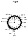
- Fig. 7 shows a flange connection structure 200A for a pipe end closing cover or a tank according to Example 2 serving to explain features of the present invention.
- Fig. 8 is a view taken along the arrowed line VIII-VIII in Fig. 7 .
- a combustible gas for example, a hydrogen gas
- a tank (not shown) having a manhole 201 closed with a cover 203.
- the cover 203 serves as a pipe end closing cover for closing the end of this pipe, and closes the end of the pipe.
- An annular seal groove 205 is formed in a flange surface 204a of a flange 204 of the cover 203.
- This seal groove 205 on the side of the cover 203 is formed on the outer peripheral side of the inner peripheral edge of a flange 202 on the side of the manhole 201 and in such a state as to surround the inner peripheral surface of the flange 202.
- a pouring passage 206 and a discharge passage 207-1 are formed in the flange 204.
- the pouring passage 206 has one end 206a opening at the circumferential surface of the outer surface of the flange 204, and has the other end 206b opening in the seal groove 205, thereby bringing the seal groove 205 and the circumferential surface of the flange into communication with each other.
- the discharge passage 207-1 has one end 207-1a opening in a space on the inner peripheral side of the manhole 201, and has the other end 207-1b opening in the seal groove 205, thereby bringing the seal groove 205 and the space on the inner peripheral side of the manhole 201 into communication with each other.
- Example 2 is different from Embodiment 2 in that the one end 207-1a of the discharge passage 207-1 is open in the space on the inner peripheral side of the manhole 201.
- the one end 207-1a of the discharge passage 207-1 may be provided with a sealing liquid leakage restricting device 207-1c.
- An annular gasket 209 is interposed between a flange surface 202a of the flange 202 and the flange surface 204a of the flange 204.
- a sealing liquid pouring section 110 has a sealing liquid pouring source 111 for ejecting a sealing liquid (for example, water or oil), a pouring pipe 112, a control valve 113, an orifice 114, a check valve 115, a pressure gauge 116, and an abnormality determination section 117.
- a sealing liquid for example, water or oil
- the pouring pressure of the sealing liquid poured from the sealing liquid pouring section 110 into the seal groove 205 via the pouring pipe 112 and the pouring passage 206 is set to be higher than the gas pressure of the combustible gas inside the tank.
- Embodiment 2 is based on the assumption that the pouring pressure of the sealing liquid is set to be lower than the gas pressure of the combustible gas inside the tank.
- Example 2 is different from Embodiment 2 in that the pouring pressure of the sealing liquid is assumed to be rendered higher than the gas pressure of the combustible gas inside the tank.
- the sealing liquid is poured from the sealing liquid pouring source 111 of the sealing liquid pouring section 110 into the seal groove 205, and held to be higher than the internal pressure, the sealing properties are enhanced.
- the sealing liquid which has leaked into the manhole 201 is separated into the gas and the liquid by a suitable separator (not shown), and recovered.
- a suitable separator not shown
- this sealing liquid inside the seal groove 205 constitutes a liquid seal structure.
- the positive pressure combustible gas inside the tank is reliably sealed up by the liquid seal structure comprising the high pressure sealing liquid charged into the seal groove 205.
- the incidence of leaks of the combustible gas can be dramatically decreased thanks to the above sealing.
- the explosion-proof range surrounding the flange connection structure 200A can be restricted to a minimum.
- the gasket 209 on the outer peripheral side performs the function of preventing the sealing liquid from leaking to the outside.
- sealing by the liquid seal structure comprising the sealing liquid charged into the seal groove 205 ensures a reliable seal, as stated above. If displacement or a gap occurs in the flange connection surface for some cause, such as an accident, however, the sealing liquid in a larger amount than the normal amount may leak into the manhole 201, whereas the combustible gas does not leak to the outside.
- the sealing liquid poured into the seal groove 205 flows out in a large amount, and the value of the detected pressure detected by the pressure gauge 116 is decreased sharply.
- the abnormality determination section 117 determines that an abnormality occurred, takes a safety measure, such as issuing an alarm, and closes the control valve 113. By so doing, a further outflow of the sealing liquid to the outside can be prevented.
- a flow meter may be installed instead of the pressure gauge 116. If the amount of the detected flow rate detected by this flowmeter increased sharply, the abnormality determination section 117 may make a determination of abnormality and take a safety measure, such as issuance of an alarm, or close the control valve 113.
- Example 2 can be applied as such even in a case where a two-phase fluid comprising a gas and a liquid mixed is stored in the tank.
- the seal groove 205, pouring passage 206, discharge passage 207, etc. are provided in the cover 203, but may be provided in the flange 202, if desired.
Landscapes
- Engineering & Computer Science (AREA)
- General Engineering & Computer Science (AREA)
- Mechanical Engineering (AREA)
- Gasket Seals (AREA)
- Filling Or Discharging Of Gas Storage Vessels (AREA)
- Flanged Joints, Insulating Joints, And Other Joints (AREA)
- Sealing Devices (AREA)
Claims (6)
- Eine Flanschverbindungsstruktur (100;200) mit einem Flansch (102;202) und einem weiterem Flansch (104;204), wobei die Flansche durch Bolzen befestigt sind, wodurch Flanschflächen (102a,104a;202a,204a) der Flansche (102,104;202,204) miteinander für eine Kopplung verbunden werden,
wobei die Flanschverbindungsstruktur (100;200) aufweist:eine ringförmige Dichtungsnut (105;205), die in der Flanschfläche (102a,104a;202a,204a) von einem der Flansche (102,104;202,204) ausgebildet ist,einen Eingießdurchgang (106;206), der in dem einen der Flansche (102,104;202,204) ausgebildet ist, um die Dichtungsnut (105;205) und eine Außenumfangsfläche des einen der Flansche (102,104;202,204) in Verbindung miteinander zu bringen, wobei ein Ende (106a;206a) des Eingießdurchgangs (106,206) an der Außenumfangsfläche offen ist,einen Auslassdurchgang (107;207), der in dem einen der Flansche ausgebildet ist, um die Dichtungsnut (105;205) und die Außenumfangsfläche des einen der Flansche (102,104;202,204) in Verbindung miteinander zu bringen, wobei ein Ende (107a;207a) des Auslassdurchgangs (107;207) an der Außenumfangsfläche offen ist,Dichtungsflüssigkeits-Eingießmittel (110), die mit dem einen Ende (106a;206a) des Eingießdurchgangs (106;206) verbunden sind, zum Eingießen einer Dichtungsflüssigkeit in die Dichtungsnut (105;205), undeine Auslassvorrichtung (120) mit einem Schwimmermechanismus und einem Auslassventil, dass mit dem einen Ende (107a;207a) des Auslassdurchgangs (107;207) verbunden ist, um ein in der Dichtungsflüssigkeit enthaltenes Gas zu einer Außenseite auszutragen, während verhindert wird, dass die Dichtungsflüssigkeit, die von dem Auslassdurchgang (107;207) ausgetreten ist, zu der Außenseite freigesetzt wird. - Die Flanschverbindungsstruktur (100;200) gemäß Anspruch 1, wobei
ein Flansch (102,104) in einem Rohr (101,103) zum Strömenlassen eines Fluids durch dieses hindurch ausgebildet ist, und der andere Flansch (102,104) in einem anderen Rohr (101,103) zum Strömenlassen des Fluids durch dieses hindurch ausgebildet ist, wobei die Flansche (102,104) durch Bolzen befestigt sind, wodurch die Flanschflächen (102a,104a) der Flansche (102,104) miteinander verbunden sind, um die Rohre (101,103) miteinander zu koppeln, oder
ein Flansch (202) in einem Zugangsloch (201) eines Tanks zum Speichern eines Fluids und der andere Flansch (204) in einer Abdeckung (203) ausgebildet ist, wobei die Flansche (202,204) durch Bolzen befestigt sind, wodurch die Flanschflächen (202a,204a) der Flansche (202,204) miteinander verbunden sind, um das Zugangsloch (201) mit der Abdeckung (203) zu verschließen, oder
ein Flansch (202) in einem Rohr (201) und der andere Flansch (204) in einer Abdeckung (203) ausgebildet ist, wobei die Flansche (202,204) durch Bolzen befestigt sind, wodurch die Flanschflächen (202a,204a) der Flansche (202,204) miteinander verbunden sind, um das Rohr (201) mit der Abdeckung (203) zu verschließen. - Die Flanschverbindungsstruktur (100;200) gemäß Anspruch 2, wobei
das Dichtungsflüssigkeits-Eingießmittel (110) so ausgestaltet ist, dass ein Eingießdruck der durch das Dichtungsflüssigkeits-Eingießmittel (110) eingegossenen Dichtungsflüssigkeit auf einen Wert eingestellt werden kann, der niedriger ist als ein Fluiddruck des Fluids. - Die Flanschverbindungsstruktur (100;200) gemäß einem der Ansprüche 1 bis 3,
wobei das Dichtungsflüssigkeits-Eingießmittel (110) mit Druckerfassungsmitteln (116) ausgestattet ist, zum Erfassen eines Drucks der in den Eingießdurchgang (106;206) eingegossenen Dichtungsflüssigkeit, oder mit Strömungsraten-Erfassungsmitteln zum Erfassen einer Strömungsrate der in den Eingießdurchgang (106,206) eingegossenen Dichtungsflüssigkeit, und
die Flanschverbindungsstruktur (100;200) ferner Abnormalitäts-Bestimmungsmittel (117) aufweist, die konfiguriert sind, um zu bestimmen, dass eine Abnormalität beim Verbinden der Flansche (102,104;202,204) aufgetreten ist, falls ein scharfer Abfall in dem durch das Druckerfassungsmittel (116) erfassten Druck aufgetreten ist, oder falls ein scharfer Anstieg in der durch das Strömungsraten-Erfassungsmittel erfassten Strömungsrate aufgetreten ist. - Die Flanschverbindungsstruktur (100;200) gemäß Anspruch 4, wobei das Abnormalitäts-Bestimmungsmittel (117) ausgestaltet ist, um eine Sicherheitsmaßnahme zu ergreifen, falls es erfasst, dass die Abnormaliät aufgetreten ist, wobei die Sicherheitsmaßnahme ein Schließen eines Steuerventils (113) umfasst, welches in ein Eingießrohr (112) eingefügt ist, das eine Dichtungsflüssigkeit-Eingießquelle (111) mit dem Eingießdurchgang (106,206) verbindet.
- Die Flanschverbindungstruktur (100,200) gemäß einem der Ansprüche 1 bis 5, wobei der Eingießdurchgang (106;206) und der Auslassdurchgang (107;207) so ausgebildet sind, dass sie um 180° bezüglich der Umfangsrichtung versetzt sind.
Applications Claiming Priority (2)
| Application Number | Priority Date | Filing Date | Title |
|---|---|---|---|
| JP2008077086A JP5297061B2 (ja) | 2008-03-25 | 2008-03-25 | フランジ接合構造 |
| EP08873565.9A EP2256393B1 (de) | 2008-03-25 | 2008-12-11 | Flanschverbindungsstruktur |
Related Parent Applications (2)
| Application Number | Title | Priority Date | Filing Date |
|---|---|---|---|
| EP08873565.9A Division-Into EP2256393B1 (de) | 2008-03-25 | 2008-12-11 | Flanschverbindungsstruktur |
| EP08873565.9A Division EP2256393B1 (de) | 2008-03-25 | 2008-12-11 | Flanschverbindungsstruktur |
Publications (2)
| Publication Number | Publication Date |
|---|---|
| EP2865930A1 EP2865930A1 (de) | 2015-04-29 |
| EP2865930B1 true EP2865930B1 (de) | 2016-10-19 |
Family
ID=41113183
Family Applications (2)
| Application Number | Title | Priority Date | Filing Date |
|---|---|---|---|
| EP14195800.9A Active EP2865930B1 (de) | 2008-03-25 | 2008-12-11 | Flanschverbindungsstruktur |
| EP08873565.9A Active EP2256393B1 (de) | 2008-03-25 | 2008-12-11 | Flanschverbindungsstruktur |
Family Applications After (1)
| Application Number | Title | Priority Date | Filing Date |
|---|---|---|---|
| EP08873565.9A Active EP2256393B1 (de) | 2008-03-25 | 2008-12-11 | Flanschverbindungsstruktur |
Country Status (6)
| Country | Link |
|---|---|
| US (1) | US8393649B2 (de) |
| EP (2) | EP2865930B1 (de) |
| JP (1) | JP5297061B2 (de) |
| KR (1) | KR101291828B1 (de) |
| CN (2) | CN101960196B (de) |
| WO (1) | WO2009118961A1 (de) |
Families Citing this family (31)
| Publication number | Priority date | Publication date | Assignee | Title |
|---|---|---|---|---|
| JP5385194B2 (ja) * | 2010-03-30 | 2014-01-08 | 高砂熱学工業株式会社 | 製氷安定方法及び氷製造装置 |
| JP5385198B2 (ja) * | 2010-03-31 | 2014-01-08 | 高砂熱学工業株式会社 | 製氷安定方法及び氷製造装置 |
| WO2013152419A1 (en) * | 2012-04-10 | 2013-10-17 | Hatch Ltd. | Conduit connection apparatus with purge gas |
| CN102661391A (zh) * | 2012-04-27 | 2012-09-12 | 南京化工特种设备检验检测研究所 | 具有压力检测控制装置的压力容器 |
| CN102878365B (zh) * | 2012-10-18 | 2015-01-14 | 航天晨光股份有限公司 | 一种滑动汇管组件 |
| NO335676B1 (no) * | 2012-12-07 | 2015-01-19 | Apl Technology As | Rørkonnektor for frigjørbar kopling av to konnektordeler i forbindelse med gasstett kopling av stigrør til fartøy |
| JP2014114849A (ja) * | 2012-12-07 | 2014-06-26 | Ihi Corp | 2重シール部のシール機構 |
| WO2014179089A1 (en) * | 2013-04-29 | 2014-11-06 | Carrier Corporation | Low leakage seal for low pressure system |
| CN103644407A (zh) * | 2013-12-11 | 2014-03-19 | 南京斯迈柯特种金属装备股份有限公司 | 双密封法兰结构 |
| CN104599039A (zh) * | 2014-12-26 | 2015-05-06 | 合肥通用机械研究院 | 一种管线智能泄漏管理系统 |
| CN106151723A (zh) * | 2015-04-20 | 2016-11-23 | 南京新核复合材料有限公司 | 一种设有单面双凹槽的密封平面法兰 |
| US10408386B2 (en) * | 2015-08-21 | 2019-09-10 | Fab-Tech, Inc. | Hot tap system and method for coated ductwork |
| KR101787965B1 (ko) * | 2015-12-02 | 2017-10-19 | 주식회사 포스코 | 가스 배관의 수봉변 감지 장치 |
| WO2017198316A1 (en) | 2016-05-20 | 2017-11-23 | Volvo Truck Corporation | A conduit connection assembly with pressure relief |
| CN105889513B (zh) * | 2016-06-07 | 2018-01-26 | 新兴铸管股份有限公司 | 一种管材真空定径箱的密封装置 |
| CN108253202A (zh) * | 2016-12-28 | 2018-07-06 | 北京市水利规划设计研究院 | 管道及其制备方法 |
| CN108131484A (zh) * | 2017-12-28 | 2018-06-08 | 安徽伙伴电气有限公司 | 一种具有侧向水封管道连接机构的陶瓷阀 |
| KR102122076B1 (ko) | 2018-05-21 | 2020-06-26 | 한국철도기술연구원 | 하이퍼튜브용 실링장치 |
| CN108775459A (zh) * | 2018-07-11 | 2018-11-09 | 天津长瑞大通流体控制系统有限公司 | 用高压液体或气体阻隔物料泄漏的垫片密封装置及方法 |
| TWM575075U (zh) * | 2018-12-13 | 2019-03-01 | 王瑞六 | Flange protection structure |
| FR3094443B1 (fr) * | 2019-03-27 | 2021-05-14 | Total Raffinage Chimie | Surveillance d’un dispositif de bride |
| CN111022645B (zh) * | 2019-11-29 | 2021-10-19 | 西安航天动力研究所 | 一种适用于高压介质的静密封结构 |
| CN112431975B (zh) * | 2020-11-04 | 2022-07-19 | 李岐 | 一种密封结构及密封方法 |
| KR102454119B1 (ko) * | 2020-11-18 | 2022-10-14 | (주)브이월드코리아 | 현장 시험이 용이한 고압 유체 수송용 플랜지관 |
| US20240027003A1 (en) * | 2020-12-04 | 2024-01-25 | Linde Gmbh | Method for producing a connection, and connection device |
| KR102489900B1 (ko) * | 2020-12-30 | 2023-01-18 | 주식회사 에네스지 | 질소를 이용한 배관 부식방지방법 및 그 배관 연결수단 |
| CN112985124A (zh) * | 2021-03-22 | 2021-06-18 | 江苏新美星包装机械股份有限公司 | 一种无菌型管式换热器 |
| FR3128759A1 (fr) * | 2021-10-28 | 2023-05-05 | Airbus | Ensemble de connexion optimise entre deux portions d’une canalisation cryogenique, comprenant une double barriere d’etancheite, une chambre d’expansion de fluide et un detecteur de presence du fluide dans ladite chambre. |
| CN114183759A (zh) * | 2021-11-18 | 2022-03-15 | 江苏西玛环境科技有限公司 | 一种基于水密封的飞灰自动化输送系统 |
| CN114856821A (zh) * | 2022-06-13 | 2022-08-05 | 杭州汽轮机股份有限公司 | 轴承座及燃气轮机 |
| FR3140604A1 (fr) * | 2022-10-11 | 2024-04-12 | Alstom Holdings | Dispositif de connexion entre un système de stockage d’hydrogène et une unité consommatrice d’hydrogène et ensemble d’alimentation en hydrogène d’un véhicule |
Family Cites Families (28)
| Publication number | Priority date | Publication date | Assignee | Title |
|---|---|---|---|---|
| US3057646A (en) * | 1959-12-23 | 1962-10-09 | Brumagim Ivan Stanley | Rotary seal with cooling means |
| US3141685A (en) * | 1960-10-11 | 1964-07-21 | Gray Tool Co | Coupling with leak detecting means and sealing ring therefor |
| FR1341382A (fr) * | 1962-12-20 | 1963-10-25 | Alpura Ag | Garniture d'étanchéité |
| US3884511A (en) * | 1972-08-10 | 1975-05-20 | Youngstown Sheet And Tube Co | Nitrogen charged swivel joint |
| JPS5053498U (de) * | 1973-09-20 | 1975-05-22 | ||
| JPS55119453U (de) * | 1979-02-18 | 1980-08-23 | ||
| US4288105A (en) * | 1979-02-21 | 1981-09-08 | Resistoflex Corporation | Pipe union with both pre-load dependent and independent seals |
| US4410186A (en) * | 1982-04-12 | 1983-10-18 | Petroleum Designers, Inc. | Sealing system for pressurized flanged joints |
| NL8304117A (nl) * | 1983-12-01 | 1985-07-01 | Single Buoy Moorings | Afdichting tussen twee ten opzichte van elkaar draaibare delen van een leidingkoppeling. |
| JPS61181186U (de) * | 1985-04-30 | 1986-11-12 | ||
| JPS6235193A (ja) * | 1985-08-07 | 1987-02-16 | 日揮株式会社 | フランジ接続部の密封用ガスケツト及び密封方法 |
| US5094109A (en) * | 1990-12-06 | 1992-03-10 | Rosemount Inc. | Pressure transmitter with stress isolation depression |
| US5090871A (en) * | 1991-02-12 | 1992-02-25 | Systems Chemistry, Inc. | Junction assembly with leak detection means |
| DE4130593A1 (de) * | 1991-09-12 | 1993-03-18 | Ratio Norm Anlagentechnik Und | Flanschverbindung |
| US5197766A (en) * | 1991-10-28 | 1993-03-30 | General Electric Company | Fluid-carrying tube coupling assembly with internal seal and drain arrangement |
| US5362115A (en) * | 1992-06-05 | 1994-11-08 | Carr Ronald L | Multi-ring gasket |
| JPH0640571U (ja) * | 1992-11-06 | 1994-05-31 | 石川島播磨重工業株式会社 | 真空用フランジ継手 |
| US5330720A (en) * | 1993-02-23 | 1994-07-19 | Hughes Aircraft Company | System for detecting fugitive emissions |
| NO311992B1 (no) * | 1995-10-26 | 2002-02-25 | Hystad Anne Elise | Anordning for lekkasjepåvisning ved trykktesting av flensskjöter på endene av rörledninger som inngår i rörsystem |
| US5762381A (en) * | 1995-12-08 | 1998-06-09 | The Perkin-Elmer Corporation | Connecting apparatus for conveyance of cryogenic fluid |
| DK0907858T3 (da) * | 1996-07-03 | 2004-02-16 | Codelast Ltd | Samlinger |
| ATE248315T1 (de) * | 1997-06-25 | 2003-09-15 | Siemens Ag | Vorrichtung zum verbinden von leitungsabschnitten |
| RU2159373C1 (ru) * | 1999-03-01 | 2000-11-20 | Открытое акционерное общество НПО "Энергомаш" им. акад. В.П. Глушко | Разъемное неподвижное уплотнительное устройство |
| JP4688117B2 (ja) | 2000-04-10 | 2011-05-25 | 株式会社アルバック | 爆発性または発火性ガスに対するシール機構 |
| JP4270074B2 (ja) | 2003-10-20 | 2009-05-27 | 日産自動車株式会社 | リザーバタンク |
| DE202006002457U1 (de) * | 2006-02-16 | 2006-05-11 | Höcketstaller, Gerhard | Sekundärdichtung für Flanschverbindungen |
| US7942452B2 (en) * | 2007-11-20 | 2011-05-17 | The Boeing Company | Flange fitting with leak sensor port |
| DE102008012739A1 (de) * | 2008-03-05 | 2009-09-10 | Oerlikon Leybold Vacuum Gmbh | Vakuum-Abgasleitungssystem |
-
2008
- 2008-03-25 JP JP2008077086A patent/JP5297061B2/ja active Active
- 2008-12-11 US US12/920,354 patent/US8393649B2/en active Active
- 2008-12-11 EP EP14195800.9A patent/EP2865930B1/de active Active
- 2008-12-11 EP EP08873565.9A patent/EP2256393B1/de active Active
- 2008-12-11 CN CN200880127655.8A patent/CN101960196B/zh active Active
- 2008-12-11 WO PCT/JP2008/072570 patent/WO2009118961A1/ja active Application Filing
- 2008-12-11 KR KR1020107018962A patent/KR101291828B1/ko active IP Right Grant
- 2008-12-11 CN CN201210049557.5A patent/CN102588592B/zh active Active
Also Published As
| Publication number | Publication date |
|---|---|
| JP2009228849A (ja) | 2009-10-08 |
| WO2009118961A1 (ja) | 2009-10-01 |
| CN101960196A (zh) | 2011-01-26 |
| EP2256393B1 (de) | 2015-08-19 |
| EP2865930A1 (de) | 2015-04-29 |
| US8393649B2 (en) | 2013-03-12 |
| EP2256393A1 (de) | 2010-12-01 |
| KR101291828B1 (ko) | 2013-07-31 |
| CN101960196B (zh) | 2015-03-11 |
| CN102588592A (zh) | 2012-07-18 |
| JP5297061B2 (ja) | 2013-09-25 |
| KR20100113597A (ko) | 2010-10-21 |
| EP2256393A4 (de) | 2014-07-02 |
| US20110012338A1 (en) | 2011-01-20 |
| CN102588592B (zh) | 2016-05-18 |
Similar Documents
| Publication | Publication Date | Title |
|---|---|---|
| EP2865930B1 (de) | Flanschverbindungsstruktur | |
| US6968851B2 (en) | Double block valve with proving system | |
| KR101130388B1 (ko) | 고압파이프용 누출 경보 | |
| CN104321628A (zh) | 一种检测流体泄露的装置 | |
| US5656766A (en) | Underground drain tank | |
| MXPA04012104A (es) | Aparato de tapa de contencion secundaria. | |
| US20160298779A1 (en) | Auxiliary flow prevention mechanism for an air valve in a pipeline | |
| US11248992B2 (en) | Systems and methods for accessing and monitoring a fluid within a pressurized pipe | |
| JP5260263B2 (ja) | フランジ接合構造 | |
| EP2267349B1 (de) | Rohrverbindungsvorrichtung | |
| KR102541108B1 (ko) | 플랜지 어셈블리 | |
| KR200385269Y1 (ko) | 액체 밀봉식 압력 진공 밸브장치 | |
| CN220503196U (zh) | 一种薄膜沉积设备及其漏液防护系统 | |
| CN220925157U (zh) | 一种挥发性液体储存和转移装置 | |
| CN220707050U (zh) | 一种新型液氯气化器 | |
| CN205982273U (zh) | 滑油管路中水分传感器安装装置 | |
| KR930016308A (ko) | 손상된 탱커로부터의 오일 누설 제어 시스템 | |
| JPH11141733A (ja) | 弁 |
Legal Events
| Date | Code | Title | Description |
|---|---|---|---|
| PUAI | Public reference made under article 153(3) epc to a published international application that has entered the european phase |
Free format text: ORIGINAL CODE: 0009012 |
|
| 17P | Request for examination filed |
Effective date: 20141202 |
|
| AC | Divisional application: reference to earlier application |
Ref document number: 2256393 Country of ref document: EP Kind code of ref document: P |
|
| AK | Designated contracting states |
Kind code of ref document: A1 Designated state(s): AT BE BG CH CY CZ DE DK EE ES FI FR GB GR HR HU IE IS IT LI LT LU LV MC MT NL NO PL PT RO SE SI SK TR |
|
| GRAP | Despatch of communication of intention to grant a patent |
Free format text: ORIGINAL CODE: EPIDOSNIGR1 |
|
| RIC1 | Information provided on ipc code assigned before grant |
Ipc: F16J 15/14 20060101ALI20160419BHEP Ipc: F16L 23/16 20060101AFI20160419BHEP |
|
| INTG | Intention to grant announced |
Effective date: 20160512 |
|
| GRAS | Grant fee paid |
Free format text: ORIGINAL CODE: EPIDOSNIGR3 |
|
| GRAA | (expected) grant |
Free format text: ORIGINAL CODE: 0009210 |
|
| AC | Divisional application: reference to earlier application |
Ref document number: 2256393 Country of ref document: EP Kind code of ref document: P |
|
| AK | Designated contracting states |
Kind code of ref document: B1 Designated state(s): AT BE BG CH CY CZ DE DK EE ES FI FR GB GR HR HU IE IS IT LI LT LU LV MC MT NL NO PL PT RO SE SI SK TR |
|
| REG | Reference to a national code |
Ref country code: GB Ref legal event code: FG4D |
|
| REG | Reference to a national code |
Ref country code: CH Ref legal event code: EP |
|
| REG | Reference to a national code |
Ref country code: AT Ref legal event code: REF Ref document number: 838652 Country of ref document: AT Kind code of ref document: T Effective date: 20161115 |
|
| REG | Reference to a national code |
Ref country code: IE Ref legal event code: FG4D |
|
| REG | Reference to a national code |
Ref country code: DE Ref legal event code: R096 Ref document number: 602008046990 Country of ref document: DE |
|
| REG | Reference to a national code |
Ref country code: NL Ref legal event code: MP Effective date: 20161019 |
|
| REG | Reference to a national code |
Ref country code: LT Ref legal event code: MG4D |
|
| PG25 | Lapsed in a contracting state [announced via postgrant information from national office to epo] |
Ref country code: LV Free format text: LAPSE BECAUSE OF FAILURE TO SUBMIT A TRANSLATION OF THE DESCRIPTION OR TO PAY THE FEE WITHIN THE PRESCRIBED TIME-LIMIT Effective date: 20161019 |
|
| REG | Reference to a national code |
Ref country code: AT Ref legal event code: MK05 Ref document number: 838652 Country of ref document: AT Kind code of ref document: T Effective date: 20161019 |
|
| PG25 | Lapsed in a contracting state [announced via postgrant information from national office to epo] |
Ref country code: GR Free format text: LAPSE BECAUSE OF FAILURE TO SUBMIT A TRANSLATION OF THE DESCRIPTION OR TO PAY THE FEE WITHIN THE PRESCRIBED TIME-LIMIT Effective date: 20170120 Ref country code: SE Free format text: LAPSE BECAUSE OF FAILURE TO SUBMIT A TRANSLATION OF THE DESCRIPTION OR TO PAY THE FEE WITHIN THE PRESCRIBED TIME-LIMIT Effective date: 20161019 Ref country code: NO Free format text: LAPSE BECAUSE OF FAILURE TO SUBMIT A TRANSLATION OF THE DESCRIPTION OR TO PAY THE FEE WITHIN THE PRESCRIBED TIME-LIMIT Effective date: 20170119 Ref country code: LT Free format text: LAPSE BECAUSE OF FAILURE TO SUBMIT A TRANSLATION OF THE DESCRIPTION OR TO PAY THE FEE WITHIN THE PRESCRIBED TIME-LIMIT Effective date: 20161019 |
|
| PG25 | Lapsed in a contracting state [announced via postgrant information from national office to epo] |
Ref country code: FI Free format text: LAPSE BECAUSE OF FAILURE TO SUBMIT A TRANSLATION OF THE DESCRIPTION OR TO PAY THE FEE WITHIN THE PRESCRIBED TIME-LIMIT Effective date: 20161019 Ref country code: ES Free format text: LAPSE BECAUSE OF FAILURE TO SUBMIT A TRANSLATION OF THE DESCRIPTION OR TO PAY THE FEE WITHIN THE PRESCRIBED TIME-LIMIT Effective date: 20161019 Ref country code: AT Free format text: LAPSE BECAUSE OF FAILURE TO SUBMIT A TRANSLATION OF THE DESCRIPTION OR TO PAY THE FEE WITHIN THE PRESCRIBED TIME-LIMIT Effective date: 20161019 Ref country code: IS Free format text: LAPSE BECAUSE OF FAILURE TO SUBMIT A TRANSLATION OF THE DESCRIPTION OR TO PAY THE FEE WITHIN THE PRESCRIBED TIME-LIMIT Effective date: 20170219 Ref country code: PL Free format text: LAPSE BECAUSE OF FAILURE TO SUBMIT A TRANSLATION OF THE DESCRIPTION OR TO PAY THE FEE WITHIN THE PRESCRIBED TIME-LIMIT Effective date: 20161019 Ref country code: BE Free format text: LAPSE BECAUSE OF FAILURE TO SUBMIT A TRANSLATION OF THE DESCRIPTION OR TO PAY THE FEE WITHIN THE PRESCRIBED TIME-LIMIT Effective date: 20161019 Ref country code: NL Free format text: LAPSE BECAUSE OF FAILURE TO SUBMIT A TRANSLATION OF THE DESCRIPTION OR TO PAY THE FEE WITHIN THE PRESCRIBED TIME-LIMIT Effective date: 20161019 Ref country code: PT Free format text: LAPSE BECAUSE OF FAILURE TO SUBMIT A TRANSLATION OF THE DESCRIPTION OR TO PAY THE FEE WITHIN THE PRESCRIBED TIME-LIMIT Effective date: 20170220 Ref country code: HR Free format text: LAPSE BECAUSE OF FAILURE TO SUBMIT A TRANSLATION OF THE DESCRIPTION OR TO PAY THE FEE WITHIN THE PRESCRIBED TIME-LIMIT Effective date: 20161019 |
|
| REG | Reference to a national code |
Ref country code: DE Ref legal event code: R097 Ref document number: 602008046990 Country of ref document: DE |
|
| PG25 | Lapsed in a contracting state [announced via postgrant information from national office to epo] |
Ref country code: RO Free format text: LAPSE BECAUSE OF FAILURE TO SUBMIT A TRANSLATION OF THE DESCRIPTION OR TO PAY THE FEE WITHIN THE PRESCRIBED TIME-LIMIT Effective date: 20161019 Ref country code: SK Free format text: LAPSE BECAUSE OF FAILURE TO SUBMIT A TRANSLATION OF THE DESCRIPTION OR TO PAY THE FEE WITHIN THE PRESCRIBED TIME-LIMIT Effective date: 20161019 Ref country code: CZ Free format text: LAPSE BECAUSE OF FAILURE TO SUBMIT A TRANSLATION OF THE DESCRIPTION OR TO PAY THE FEE WITHIN THE PRESCRIBED TIME-LIMIT Effective date: 20161019 Ref country code: DK Free format text: LAPSE BECAUSE OF FAILURE TO SUBMIT A TRANSLATION OF THE DESCRIPTION OR TO PAY THE FEE WITHIN THE PRESCRIBED TIME-LIMIT Effective date: 20161019 Ref country code: EE Free format text: LAPSE BECAUSE OF FAILURE TO SUBMIT A TRANSLATION OF THE DESCRIPTION OR TO PAY THE FEE WITHIN THE PRESCRIBED TIME-LIMIT Effective date: 20161019 |
|
| REG | Reference to a national code |
Ref country code: CH Ref legal event code: PL |
|
| PLBE | No opposition filed within time limit |
Free format text: ORIGINAL CODE: 0009261 |
|
| STAA | Information on the status of an ep patent application or granted ep patent |
Free format text: STATUS: NO OPPOSITION FILED WITHIN TIME LIMIT |
|
| PG25 | Lapsed in a contracting state [announced via postgrant information from national office to epo] |
Ref country code: BG Free format text: LAPSE BECAUSE OF FAILURE TO SUBMIT A TRANSLATION OF THE DESCRIPTION OR TO PAY THE FEE WITHIN THE PRESCRIBED TIME-LIMIT Effective date: 20170119 Ref country code: IT Free format text: LAPSE BECAUSE OF FAILURE TO SUBMIT A TRANSLATION OF THE DESCRIPTION OR TO PAY THE FEE WITHIN THE PRESCRIBED TIME-LIMIT Effective date: 20161019 |
|
| 26N | No opposition filed |
Effective date: 20170720 |
|
| GBPC | Gb: european patent ceased through non-payment of renewal fee |
Effective date: 20170119 |
|
| PG25 | Lapsed in a contracting state [announced via postgrant information from national office to epo] |
Ref country code: MC Free format text: LAPSE BECAUSE OF FAILURE TO SUBMIT A TRANSLATION OF THE DESCRIPTION OR TO PAY THE FEE WITHIN THE PRESCRIBED TIME-LIMIT Effective date: 20161019 |
|
| REG | Reference to a national code |
Ref country code: FR Ref legal event code: ST Effective date: 20170831 |
|
| REG | Reference to a national code |
Ref country code: IE Ref legal event code: MM4A |
|
| PG25 | Lapsed in a contracting state [announced via postgrant information from national office to epo] |
Ref country code: LU Free format text: LAPSE BECAUSE OF NON-PAYMENT OF DUE FEES Effective date: 20161211 Ref country code: LI Free format text: LAPSE BECAUSE OF NON-PAYMENT OF DUE FEES Effective date: 20161231 Ref country code: FR Free format text: LAPSE BECAUSE OF NON-PAYMENT OF DUE FEES Effective date: 20170102 Ref country code: CH Free format text: LAPSE BECAUSE OF NON-PAYMENT OF DUE FEES Effective date: 20161231 |
|
| PG25 | Lapsed in a contracting state [announced via postgrant information from national office to epo] |
Ref country code: IE Free format text: LAPSE BECAUSE OF NON-PAYMENT OF DUE FEES Effective date: 20161211 Ref country code: SI Free format text: LAPSE BECAUSE OF FAILURE TO SUBMIT A TRANSLATION OF THE DESCRIPTION OR TO PAY THE FEE WITHIN THE PRESCRIBED TIME-LIMIT Effective date: 20161019 Ref country code: GB Free format text: LAPSE BECAUSE OF NON-PAYMENT OF DUE FEES Effective date: 20170119 |
|
| PG25 | Lapsed in a contracting state [announced via postgrant information from national office to epo] |
Ref country code: HU Free format text: LAPSE BECAUSE OF FAILURE TO SUBMIT A TRANSLATION OF THE DESCRIPTION OR TO PAY THE FEE WITHIN THE PRESCRIBED TIME-LIMIT; INVALID AB INITIO Effective date: 20081211 |
|
| PG25 | Lapsed in a contracting state [announced via postgrant information from national office to epo] |
Ref country code: CY Free format text: LAPSE BECAUSE OF FAILURE TO SUBMIT A TRANSLATION OF THE DESCRIPTION OR TO PAY THE FEE WITHIN THE PRESCRIBED TIME-LIMIT Effective date: 20161019 |
|
| PG25 | Lapsed in a contracting state [announced via postgrant information from national office to epo] |
Ref country code: MT Free format text: LAPSE BECAUSE OF NON-PAYMENT OF DUE FEES Effective date: 20161211 |
|
| PG25 | Lapsed in a contracting state [announced via postgrant information from national office to epo] |
Ref country code: TR Free format text: LAPSE BECAUSE OF FAILURE TO SUBMIT A TRANSLATION OF THE DESCRIPTION OR TO PAY THE FEE WITHIN THE PRESCRIBED TIME-LIMIT Effective date: 20161019 |
|
| PGFP | Annual fee paid to national office [announced via postgrant information from national office to epo] |
Ref country code: DE Payment date: 20231031 Year of fee payment: 16 |