EP2852882B1 - Verfahren und vorrichtung zur steuerung einer benutzerschnittstelle mittels eines berührungsbildschirms - Google Patents
Verfahren und vorrichtung zur steuerung einer benutzerschnittstelle mittels eines berührungsbildschirms Download PDFInfo
- Publication number
- EP2852882B1 EP2852882B1 EP13793991.4A EP13793991A EP2852882B1 EP 2852882 B1 EP2852882 B1 EP 2852882B1 EP 13793991 A EP13793991 A EP 13793991A EP 2852882 B1 EP2852882 B1 EP 2852882B1
- Authority
- EP
- European Patent Office
- Prior art keywords
- user
- screen
- uis
- touchable
- comfort zone
- Prior art date
- Legal status (The legal status is an assumption and is not a legal conclusion. Google has not performed a legal analysis and makes no representation as to the accuracy of the status listed.)
- Active
Links
- 238000000034 method Methods 0.000 title claims description 20
- 230000008707 rearrangement Effects 0.000 claims description 15
- 238000013507 mapping Methods 0.000 claims description 13
- 230000004044 response Effects 0.000 claims description 6
- 238000011084 recovery Methods 0.000 claims description 5
- 210000003813 thumb Anatomy 0.000 description 28
- 230000009466 transformation Effects 0.000 description 11
- 230000006870 function Effects 0.000 description 10
- 239000011159 matrix material Substances 0.000 description 10
- 238000009472 formulation Methods 0.000 description 5
- 239000000203 mixture Substances 0.000 description 5
- 238000012423 maintenance Methods 0.000 description 4
- 230000003247 decreasing effect Effects 0.000 description 3
- 238000001514 detection method Methods 0.000 description 3
- 210000003811 finger Anatomy 0.000 description 3
- 230000008859 change Effects 0.000 description 2
- 238000010586 diagram Methods 0.000 description 2
- 230000014509 gene expression Effects 0.000 description 2
- 238000005259 measurement Methods 0.000 description 2
- 238000012986 modification Methods 0.000 description 2
- 230000004048 modification Effects 0.000 description 2
- 238000012545 processing Methods 0.000 description 2
- 238000006243 chemical reaction Methods 0.000 description 1
- 238000004891 communication Methods 0.000 description 1
- 238000004590 computer program Methods 0.000 description 1
- 238000010276 construction Methods 0.000 description 1
- 238000013500 data storage Methods 0.000 description 1
- 230000008034 disappearance Effects 0.000 description 1
- 230000000694 effects Effects 0.000 description 1
- 230000002708 enhancing effect Effects 0.000 description 1
- 230000010365 information processing Effects 0.000 description 1
- 239000004973 liquid crystal related substance Substances 0.000 description 1
- 230000003287 optical effect Effects 0.000 description 1
- 230000008569 process Effects 0.000 description 1
- 238000013341 scale-up Methods 0.000 description 1
- 239000010409 thin film Substances 0.000 description 1
Images


Classifications
-
- G—PHYSICS
- G06—COMPUTING; CALCULATING OR COUNTING
- G06F—ELECTRIC DIGITAL DATA PROCESSING
- G06F3/00—Input arrangements for transferring data to be processed into a form capable of being handled by the computer; Output arrangements for transferring data from processing unit to output unit, e.g. interface arrangements
- G06F3/01—Input arrangements or combined input and output arrangements for interaction between user and computer
- G06F3/03—Arrangements for converting the position or the displacement of a member into a coded form
- G06F3/041—Digitisers, e.g. for touch screens or touch pads, characterised by the transducing means
-
- G—PHYSICS
- G06—COMPUTING; CALCULATING OR COUNTING
- G06F—ELECTRIC DIGITAL DATA PROCESSING
- G06F3/00—Input arrangements for transferring data to be processed into a form capable of being handled by the computer; Output arrangements for transferring data from processing unit to output unit, e.g. interface arrangements
- G06F3/01—Input arrangements or combined input and output arrangements for interaction between user and computer
- G06F3/048—Interaction techniques based on graphical user interfaces [GUI]
- G06F3/0487—Interaction techniques based on graphical user interfaces [GUI] using specific features provided by the input device, e.g. functions controlled by the rotation of a mouse with dual sensing arrangements, or of the nature of the input device, e.g. tap gestures based on pressure sensed by a digitiser
- G06F3/0488—Interaction techniques based on graphical user interfaces [GUI] using specific features provided by the input device, e.g. functions controlled by the rotation of a mouse with dual sensing arrangements, or of the nature of the input device, e.g. tap gestures based on pressure sensed by a digitiser using a touch-screen or digitiser, e.g. input of commands through traced gestures
-
- G—PHYSICS
- G06—COMPUTING; CALCULATING OR COUNTING
- G06F—ELECTRIC DIGITAL DATA PROCESSING
- G06F3/00—Input arrangements for transferring data to be processed into a form capable of being handled by the computer; Output arrangements for transferring data from processing unit to output unit, e.g. interface arrangements
- G06F3/01—Input arrangements or combined input and output arrangements for interaction between user and computer
- G06F3/048—Interaction techniques based on graphical user interfaces [GUI]
- G06F3/0481—Interaction techniques based on graphical user interfaces [GUI] based on specific properties of the displayed interaction object or a metaphor-based environment, e.g. interaction with desktop elements like windows or icons, or assisted by a cursor's changing behaviour or appearance
- G06F3/0482—Interaction with lists of selectable items, e.g. menus
-
- G—PHYSICS
- G06—COMPUTING; CALCULATING OR COUNTING
- G06F—ELECTRIC DIGITAL DATA PROCESSING
- G06F3/00—Input arrangements for transferring data to be processed into a form capable of being handled by the computer; Output arrangements for transferring data from processing unit to output unit, e.g. interface arrangements
- G06F3/01—Input arrangements or combined input and output arrangements for interaction between user and computer
- G06F3/048—Interaction techniques based on graphical user interfaces [GUI]
- G06F3/0481—Interaction techniques based on graphical user interfaces [GUI] based on specific properties of the displayed interaction object or a metaphor-based environment, e.g. interaction with desktop elements like windows or icons, or assisted by a cursor's changing behaviour or appearance
-
- G—PHYSICS
- G06—COMPUTING; CALCULATING OR COUNTING
- G06F—ELECTRIC DIGITAL DATA PROCESSING
- G06F3/00—Input arrangements for transferring data to be processed into a form capable of being handled by the computer; Output arrangements for transferring data from processing unit to output unit, e.g. interface arrangements
- G06F3/01—Input arrangements or combined input and output arrangements for interaction between user and computer
- G06F3/048—Interaction techniques based on graphical user interfaces [GUI]
- G06F3/0487—Interaction techniques based on graphical user interfaces [GUI] using specific features provided by the input device, e.g. functions controlled by the rotation of a mouse with dual sensing arrangements, or of the nature of the input device, e.g. tap gestures based on pressure sensed by a digitiser
- G06F3/0488—Interaction techniques based on graphical user interfaces [GUI] using specific features provided by the input device, e.g. functions controlled by the rotation of a mouse with dual sensing arrangements, or of the nature of the input device, e.g. tap gestures based on pressure sensed by a digitiser using a touch-screen or digitiser, e.g. input of commands through traced gestures
- G06F3/04886—Interaction techniques based on graphical user interfaces [GUI] using specific features provided by the input device, e.g. functions controlled by the rotation of a mouse with dual sensing arrangements, or of the nature of the input device, e.g. tap gestures based on pressure sensed by a digitiser using a touch-screen or digitiser, e.g. input of commands through traced gestures by partitioning the display area of the touch-screen or the surface of the digitising tablet into independently controllable areas, e.g. virtual keyboards or menus
-
- H—ELECTRICITY
- H04—ELECTRIC COMMUNICATION TECHNIQUE
- H04M—TELEPHONIC COMMUNICATION
- H04M1/00—Substation equipment, e.g. for use by subscribers
- H04M1/72—Mobile telephones; Cordless telephones, i.e. devices for establishing wireless links to base stations without route selection
- H04M1/724—User interfaces specially adapted for cordless or mobile telephones
- H04M1/72448—User interfaces specially adapted for cordless or mobile telephones with means for adapting the functionality of the device according to specific conditions
-
- H—ELECTRICITY
- H04—ELECTRIC COMMUNICATION TECHNIQUE
- H04M—TELEPHONIC COMMUNICATION
- H04M2250/00—Details of telephonic subscriber devices
- H04M2250/22—Details of telephonic subscriber devices including a touch pad, a touch sensor or a touch detector
Definitions
- the present invention relates to a touch screen that provides a User Interface (UI). More particularly, the present invention relates to a method and apparatus of controlling a UI to increase user convenience.
- UI User Interface
- Digital portable terminals such as smart phones, tablet Personal Computers (PCs), e-book readers, and the like have rapidly gained popularity and their roles, uses and functions have changed.
- Smart phones which are being widely used, function additionally as an information processor like a personal information manager, in addition to the role of a personal portable communication device.
- an object-oriented information input means is used for a digital portable terminal in order to enhance user convenience.
- the digital portable terminal is equipped with a touch screen to allow a user to input necessary information conveniently and to process the input information.
- a user may be inconvenienced when the user selects and inputs information on the touch screen of a digital portable terminal because of the different sizes of the touch screens.
- the different sizes of the touch screens are developed and widely equipped for digital portable terminals.
- a larger touch screen relatively in a digital portable terminal is difficult to touch by one-hand users,
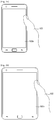
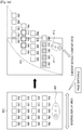
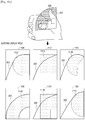
- FIGS. 1A and 1B illustrate a limitation of a larger touch screen in a digital portable terminal, in terms of a touchable area according to the related art.
- FIG. 1B illustrates a larger touch screen 100b in a smart phone than a touch screen 100a in a related-art smart phone illustrated in FIG. 1A .
- a part of the touch screen 100b in the smart phone illustrated in FIG. 1B may be untouchable or inaccessible for touching by a user according to the use environment of an input means because the touch screen 100b is relatively large.
- the user's hand may be used as the input means of the smart phone.
- a user that manipulates a digital portable terminal with one hand is referred to as a 'one-hand user'.
- a one-hand user should first hold the smart phone. Specifically, the user holds the smart phone with the other four fingers of one hand except for the thumb. Then, the one-hand user inputs information to the smart phone, mainly with a thumb 105.
- the one-hand user may reach the entire display area of the touch screen 100a of the related-art smart phone with the thumb 105 to manipulate the touch screen 100a.
- the manipulation area is confined to a part of the touch screen 100b larger than the touch screen 100a and thus there are areas beyond reach of the thumb 105, i.e. areas that cannot be touched by the thumb 105 or areas above which the thumb 105 cannot be placed, on the touch screen 100b.
- UIs are arranged in an array having grids at predetermined intervals on the touch screen or UIs are confined to a specific position on the touch screen in order to receive a user input.
- JP 2011 086036 and US 2010/241985 disclose electronic equipment to display an icon group in an appropriate range desired by a user.
- WO 2011/135944 discloses an information processing terminal in which a control unit displays operational objects or icons to an icon gathering area.
- a user may be inconvenienced when the user selects and inputs information on the touch screen of a digital portable terminal because of the different sizes of the touch screens.
- the different sizes of the touch screens are developed and widely equipped for digital portable terminals.
- a larger touch screen relatively in a digital portable terminal is difficult to touch by one-hand users.
- an aspect of the present invention is to provide a method of determining a part of the display area of a touch screen as a user-touchable area and providing User Interfaces (UIs) in the user-touchable area, and a touch screen using the method.
- UIs User Interfaces
- Exemplary embodiments of the present invention will be provided to achieve the above-described technical aspects of the present invention.
- defined entities may have the same names, to which the present invention is not limited.
- exemplary embodiments of the present invention can be implemented with same or ready modifications in a system having a similar technical background.
- the present invention provides a method of determining a part of a touch screen having a user-untouchable display area as a user-touchable area and rearranging User Interfaces (UIs) in the user-touchable area.
- UIs may be any graphical element displayed on a touch screen that a user may interact and/ or interface with, such as a button, an icon, a symbol, a command, a picture, a video, and any other similar and/or suitable element that is graphically displayed on a touch screen and/or display device.
- an input means for a touch screen having a user-untouchable display area is a user's one hand, by way of example.
- the present invention is not limited thereto, and the input means may be any suitable and/or similar input means, such as any finger of a user and a stylus.
- a user that manipulates a digital portable terminal with one hand is referred to as a 'one-hand user'.
- the input means is not limited to a user's one hand in the present invention.
- a touchable part of the display area of a touch screen is defined as a user-touchable area according to an exemplary embodiment of the present invention.
- the user-touchable area includes an area touchable by an input means and an area above which the input means may be placed although the input means does not contact the touch screen in the display area of the touch screen.
- an input to the touch screen for example, a motion of a user s hand or a stylus pen is recognized by motion recognition.
- the touch screen of the present exemplary embodiments may have a relatively large screen size, compared to a related-art touch screen.
- a touch screen includes the user-untouchable area, i.e. an area untouchable and/or unreachable by an input means according to a user s reach or an area above which the input means cannot be placed, the present exemplary embodiments are applicable to the touch screen.
- an input means by which to determine a user-touchable partial area is a thumb of a one-hand user.
- the user-touchable partial area is called a comfort zone defined as an area touchable by the thumb. While the exemplary embodiments of the present invention will be described using the term 'comfort zone' the comfort zone is interchangeable with the user-touchable partial area having the same meaning.
- FIG. 2 illustrates a comfort zone defined according to an exemplary embodiment of the present invention.
- the one-hand user when a one-hand user manipulates a portable digital terminal having a touch screen with one hand, the one-hand user may shape the hand as illustrated in FIG. 2 .
- the one-hand user holds the digital portable terminal with the other four fingers of the hand except for the thumb.
- the user inputs information such as a specific request by touching the display area of the touch screen with the thumb.
- a fan-shaped area 200 defines a range in which the thumb may reach on the touch screen.
- a comfort zone 205 may be defined as an area which can be touched by the thumb of the one-hand user or an area above which the thumb can be placed, i.e. the whole fan-shaped area 200.
- the comfort zone 205 may be defined as a part of the fan-shaped area 200, which is readily touchable by the thumb or easily sensible, e.g. a shaded part of the fan-shaped area 200.
- Exemplary embodiments of the present invention provide a method of rearranging UIs in a comfort zone by adjusting the positions, intervals, and layout of the UIs so that the one-hand user may conveniently manipulate a user device.
- the exemplary embodiments of the present invention also provide additional UIs with which a user uses UIs rearranged in a comfort zone, taking into account user experience.
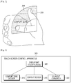
- FIG. 3 is a block diagram of a touch screen control apparatus according to an exemplary embodiment of the present invention.
- a touch screen control apparatus 300 performs specific operations to display information on the touch screen of a digital portable terminal that a one-hand user manipulates.
- the touch screen control apparatus 300 includes a display unit 305 which may be a touch screen, a comfort zone decider 310, a context decider 315, and a UI layout converter 320.
- the display unit 305 may be any type of display unit for displaying graphical information, such as a Liquid Crystal Display (LCD) unit, a Light Emitting Diode (LED) display unit, a Thin-Film Transistor (TFT) display unit, an Organic LED (OLED) display unit, or any other similar and/or suitable type of display unit.
- LCD Liquid Crystal Display
- LED Light Emitting Diode
- TFT Thin-Film Transistor
- OLED Organic LED
- the comfort zone decider 310, the context decider 315, and the UI layout converter 320 may be incorporated into a controller (not shown), or any other similar and/or suitable type of hardware, in a digital portable terminal having the touch screen control apparatus 300 of FIG. 3 .
- the controller may be configured as at least one processor having a program to control the operation of the display unit 305 and UI operations according to the exemplary embodiments of the present invention.
- the touch screen control apparatus 300 may further include a motion sensor (not shown).
- the comfort zone decider 310 receives a user input needed to determine a comfort zone and determines a comfort zone based on the user input.
- the context decider 315 determines the type of content for which a current UI is activated.
- the UI layout converter 320 renders a graphic image on the display unit 305 and re-adjusts a screen configuration including the sizes, intervals, and layout of UIs in the determined comfort zone according to an exemplary embodiment of the present invention.
- the display unit 305 displays a graphic image including the UIs rearranged in the comfort zone in a display area. Operations of the components of the touch screen control apparatus 300 will be described below in greater detail.
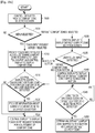
- FIG. 4A is a flowchart illustrating an operation of a comfort zone decider in a touch screen control apparatus according to an exemplary embodiment of the present invention
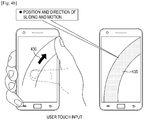
- FIG. 4B illustrates a user touch input according to an exemplary embodiment of the present invention
- FIG. 4C illustrates a method of determining a comfort zone according to an exemplary embodiment of the present invention.
- the comfort zone decider is the comfort zone decider 310 of FIG. 3 .
- the comfort zone decider 310 controls the display unit 305 to display a comfort zone selection screen (not shown) to determine a comfort zone and then proceeds to step 405.
- the comfort zone selection may be, for example, a locked home screen or an additional screen requesting a user touch input. Whether the display unit 305 is to display the locked home screen or the additional screen requesting a user touch input may be preset by a user or by default by a manufacturer.
- step 405 the comfort zone decider 310 determines whether a user touch input has been detected.
- the one-hand user touches the touch screen corresponding to the display unit 305. Specifically, the one-hand user touches a partial area 430 of the touch screen with a thumb.
- the touch includes a sliding or drag motion. For example, if a locked home screen is provided as a comfort zone selection, the one-hand user may unlock the screen by sliding or dragging the thumb across the touch screen.
- the comfort zone decider 310 determines that a user touch input has been detected and goes to step 410. On the contrary, in the absence of a user touch input or if detection of a user touch input is not recognized, the comfort zone decider 310 awaits reception of a user touch input in step 400. Specifically, the comfort zone decider 310 may await reception of a user touch input to unlock the screen or may control the display unit 305 to display an additional touch input request screen on the touch screen.
- the comfort zone decider 310 may provide a screen from which the user may select a preset default comfort zone. Default comfort zones will be described later in greater detail.
- the comfort zone decider 310 determines the partial area touched by the thumb as a comfort zone.
- a user-touchable partial area 440 is not confined to an actual area touched by a thumb of a one-hand user. Specifically, if the one-hand user touches only a specific part 441 of the area 440 with the thumb as illustrated in screen 450 of FIG. 4C , the comfort zone decider 310 determines whether the user has slided or dragged the thumb, for example, from right to left or from left to right, estimates a touchable area based on the specific touched area and the touched direction, and determines the estimated touchable area as a comfort zone.
- the comfort zone decider 310 controls the display unit 305 to display the comfort zone so that the user may identify the comfort zone.
- the display unit 305 may display the boundaries of the comfort zone or the full comfort zone on the touch screen.
- the comfort zone decider 310 controls the display unit 305 to display a screen that prompts the user to maintain or adjust the comfort zone in step 415.
- the comfort zone decider 310 receives a user input in response to the question.
- the providing of the screen asking the user whether to maintain or adjust a comfort zone may be set by default in the digital portable terminal by the manufacturer or freely set by the user during initial setting of the digital portable terminal, and the screen may be configured to prompt the user to make a choice between maintenance and adjustment of a comfort zone.
- the comfort zone decider 310 determines the determined comfort zone as a current comfort zone and provides information about the current comfort zone to the UI layout converter 320 in step 420. On the contrary, if the user input indicates adjustment of the comfort zone, then the comfort zone decider 310 controls the display unit 305 to provide a touch input request screen so that the user may adjust the comfort zone in step 425. Specifically, the display unit 305 displays boundaries 443 and 445 of the determined comfort zone on the touch screen under the control of the comfort zone decider 310, as illustrated in screen 451 of FIG. 4C .
- the boundary 445 is placed in an adjustable state. Then the user adjusts the size of the comfort zone by dragging the clicked boundary 445 to an intended position 449.
- the other boundary 443 may be adjusted in the same manner.
- Clicking and/or dragging used to adjust a comfort zone is an exemplary user input. Therefore, an operation of placing a boundary of a comfort zone to an adjustable state and an operation of adjusting the selected boundary may be performed by predefined various inputs. For example, when a boundary of a comfort zone is placed in an adjustable state by clicking on the boundary, then the boundary of the comfort zone may be changed by a predetermined extent at each click or each time a predetermined motion is recognized.
- the context decider 315 determines the type of content to be provided in the comfort zone.
- Table 1 below lists exemplary content types that the context decider 315 of the touch screen control apparatus 300 determines to provide on UIs in the comfort zone. If content is provided on UIs with no distinction made between a comfort zone and a non-comfort zone or if content of a predetermined type is provided on UIs in the comfort zone, then the context decider 315 may not be included in the touch screen control apparatus 300.
- content types include, for example, icons, an application control UI, a page view, and a list view.
- the icons are arranged on a home screen displayed on the touch screen of a digital portable terminal that a one-hand user manipulates and each icon provides a function of executing an application mapped to the icon.
- the application control UI provides a function of executing a manipulation function such as play, stop, pause and the like of a video player.
- the page view provides a function of returning to the previous page or moving to the next page on an e-book or a Web page.
- the list view provides a function of listing specific items on the touch screen.
- FIG. 5A is a flowchart illustrating an operation of a UI layout converter in a touch screen control apparatus according to an exemplary embodiment of the present invention.
- the UI layout converter is the UI layout converter 320 of FIG. 3 .
- the UL layout converter 320 acquires information about a determined comfort zone from the comfort zone decider 310 in step 500.
- the UI layout converter 320 divides an existing display area prior to a layout change to the comfort zone, which may be referred to as an existing display area, into a plurality of sub-areas and calculates the coordinates of each sub-area. While rectangles, parallelograms, trapezoids, and the like are available as the shapes of the sub-areas, the following description will be given in the context of each sub-area being a parallelogram, by way of example.
- the UI Layout converter 320 divides the comfort zone into sub-areas and calculates coordinates of the sub-areas.
- the UI layout converter 320 calculates a mapping relationship between the coordinates of the display area and the coordinates of the comfort zone. A manner in which the UI layout converter 320 calculates the mapping relationship will be described later in greater detail according to an exemplary embodiment of the present invention.
- the UI layout converter 320 converts UIs arranged in the existing display area to UIs for the comfort zone.
- FIG. 5B illustrates two-dimensional projective transformation between an existing display area and a current comfort zone according to an exemplary embodiment of the present invention.
- an existing display area 550 is divided into, for example, sub-areas, e.g. n rectangles P 1 ,P 2 ,...,P n , each having a predetermined size along a vertical axis in step 502.
- a comfort zone 560 is divided into sub-areas, e.g. n squares C 1 ,C 2 ,...,C n , corresponding to the n rectangles P 1 ,P 2 ,...,P n in step 504.
- the UI layout converter 320 determines the mapping relationship between the coordinates of the n rectangles P 1 ,P 2 ,...,P n and the coordinates of the squares C 1 ,C 2 ,...,C n by two-dimensional projective transformation.
- the two-dimensional projective transformation may be defined as the following table. [Table 2] 2D Projective Transform [t] Sometimes called homography or collineation.
- a first rectangle PI which is divided from the existing display area 550, may be represented by the coordinates of four points 501, 503, 505 and 507.
- the square C1 of the comfort zone 560 corresponding to the rectangle P 1 may be represented by the coordinates of four points 511, 513, 515 and 517.
- the UI layout converter 320 calculates a matrix A having, as elements, mapping relationships between the coordinates of the points 501, 503, 505, and 507 of the rectangle P 1 and the coordinates of the points 511, 513, 515, and 517 of the square C1 by two-dimensional projective transformation.
- the UI layout converter 320 may express the coordinates x 1 and x 2 of the first point 501 of the rectangle P 1 using the coordinates u 1 and u 2 of the first point 511 of the square C 1 according to Equation (1).
- the UI layout converter 320 changes x 1 and x 2 in Equation (1) to the expression of Equation (2).
- x 1 A 1 u T 1 T A 3 u T 1
- x 2 A 2 u T 1 T A 3 u T 1 T
- the UI layout converter 320 determines the matrix A with a total of nine elements a 11 ,a 12 ,a 13 ,...,a 33 of the variables A 1 ,A 2 , and A 3 .
- the matrix A is expressed as Equation (3).
- A A 1 A 2
- a 3 a 11 a 12 a 13 a 21 a 22 a 23 a 31 a 32 a 33
- one of the coordinate pairs, i.e. a first coordinate pair, of the existing display area 550 and one of the coordinate pairs, i.e. a second coordinate pair, of the comfort zone 560 may be expressed as a matrix A with nine elements.
- the coordinates of the four points 511, 513, 515 and 517 of the square C 1 corresponding to the coordinates of the four points 501, 503, 505 and 507 of the rectangle P 1 may be obtained. Accordingly, once the four coordinate pairs of the rectangle P 1 and the four coordinate pairs of the square C 1 corresponding to the rectangle P 1 are determined, four implementations of Equation(1) and four implementation of Equation(2) describe the respective mapping relationships between the four coordinate pairs of the rectangle P 1 and the four coordinate pairs of the square C 1 , and thus a total of eighte quations exist. Then any point of the rectangle P 1 may be converted to a point of the square C 1 using one matrix A describing the mapping relationship between the rectangle P 1 and the square C 1 .
- Matrices A are calculated with regards to the mapping relationships between the coordinates of the other rectangles P 2 ,...,P n and the coordinates of the other squares C 2 , ..., C n in the same manner. Then the coordinates of a point of a rectangle are converted to the coordinates of a point of a parallelogram corresponding to the rectangle, i.e. the coordinates of a point of the comfort zone 560.
- the UI layout converter 320 calculates a matrix A using the first coordinate pairs of four points of each of the sub-areas of an existing display area 550 and the second coordinate pairs of four points of a comfort zone 560, e.g. the coordinates of the points of a parallelogram, corresponding to the first coordinate pairs by Least Square (LSQ) formulation, such as a least square method, RANdom Sample Consensus (RANSAC), or the like.
- LSQ Least Square
- RANSAC Random Sample Consensus
- the UI layout converter 320 may express vector a from the elements of the matrix A according to Equation (4).
- a A 1 A 2
- a 3 a 11 a 12 a 13 a 21 a 22 a 23 a 31 a 32 a 33 T
- the UI layout converter 320 may obtain the comfort zone conversion vector a expressed as Equation (6) by representing a homogeneous equation according to Equation (5).
- Equation (6) u 1 1 u 2 1 1 0 0 0 ⁇ x 1 1 u 1 1 ⁇ x 1 1 u 2 1 ⁇ x 1 1 0 0 0 u 1 1 u 2 1 1 ⁇ x 2 1 u 1 1 ⁇ x 2 1 u 2 1 ⁇ x 2 1 ⁇ x 2 1 ⁇ x 2 1 ⁇ x 2 1 . . . . . . . . . . . . . . . . . . . . . . . . . . . . . . .
- the UI layout converter 320 calculates matrices A that describe the mapping relationships between the first coordinate pairs of the points of each sub-area divided from the existing display area and the second coordinate pairs of the points of each sub-area divided from the comfort zone in step 506 and converts UIs in the existing display area to UIs in the comfort zone based on the matrices A in step 508. Specifically, the mapping relationship A between each sub-area of the existing display area and a corresponding sub-area of the comfort zone is determined. Then the coordinates of UIs within the sub-areas of the existing display area are converted to coordinates corresponding to the UIs in the sub-areas of the comfort zone based on the determined matrices A.
- the first coordinate pairs of the positions of the UIs in the existing display area may be converted to the second coordinate pairs of positions of the UIs in the comfort zone.
- the UI layout converter 320 may adjust at least one of the positions, sizes, and shapes of the UIs in the comfort zone.
- FIG. 6 illustrates a comfort zone according to an exemplary embodiment of the present invention.
- an outer area 630 shown as a shaded part, of the comfort zone may be outside the boundary of the display area of the touch screen.
- the comfort zone may be larger or smaller than the existing display area. Compared to the display area, the comfort zone may be streamlined or distorted in shape. Therefore, there may exist a need for adjusting the sizes, intervals, and layout of icons displayed in the display area, when the display area is transformed to the comfort zone.
- the UI layout converter 320 may move UIs located in the outer area 630 to the next page, scale down the sizes of the UIs, or change the shapes of the UIs by adjusting at least one of the positions, sizes, and shapes of UIs, e.g.
- the UI layout converter 320 may control the display unit 305 to display an additional screen requesting a user input for UI adjustment.
- the UI layout converter 320 may also control the display unit 305 to display a screen requesting input of the number of uses of each icon. For example, upon receipt of the number of uses of each icon, the UI layout converter 320 may control the display unit 305 to arrange icons having the numbers of uses smaller than a predetermined threshold in the outer area 630. Adjustment of UIs in the comfort zone may be optional.
- the exemplary embodiments have described above with reference to FIGS. 5A, 5B and 6 such that UIs of an existing display area are converted to UIs of a comfort zone by two-dimensional projective transformation according to the exemplary embodiment of the present invention.
- the two-dimensional projective transformation is an exemplary method of converting UIs of the display area to UIs of the comfort zone and thus the present invention is not limited to the two-dimensional projective transformation.
- a method of converting UIs of an existing display area to UIs of a comfort zone will be described.
- a plurality of default comfort zones are pre-stored during initial setting of a touch screen by the manufacturer.
- the default comfort zones are formed into shapes that users are likely to frequently use.
- the comfort zone decider 310 it is also possible for the comfort zone decider 310 to additionally determine a comfort zone based on a user s preference according to a user selection. If each of the default comfort zones includes UIs transformed from UIs of the display area, upon user selection of one of the default comfort zones, an operation of adjusting preset UIs of the selected default comfort zone may be performed selectively.
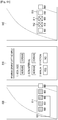
- FIG. 7 illustrates the shapes of various comfort zones and the positions and sizes of icons adjusted according to the shapes of the comfort zones according to an exemplary embodiment of the present invention.
- icons are taken as an exemplary content type displayed in a display area 700, the present invention is not limited thereto, and the present exemplary embodiment is also applicable to other types of content such as a control UI, a page view, and a list view.
- the display area 700 generally displays icons across the whole area of a touch screen.
- the icons are arranged equidistantly at their original positions 705.
- Each icon is spaced from its upper, lower, left, and right adjacent icons by the same distance.
- the icons displayed in the display area 700 are of the same size. While the icons have the same distance and size in the exemplary embodiment of FIG. 7 , the sizes and positions of icons arranged in the display area may be adjusted according to a user setting.
- the icons mapped to the display area 700 are rearranged at new coordinates in a predetermined comfort zone by two-dimensional projective transformation described above with reference to the exemplary embodiments of FIGS. 5A and 5B .
- various shapes are available to a comfort zone according to a user input.
- the icons of the display area 700 are displayed at new coordinates corresponding to the original icon positions 705 in comfort zones 710, 720 and 730, which may also be respectively referred to as comfort zones 1-1,2-1, and 3-1.
- the icons of the display area 700 are moved to new coordinates mapped to the original positions of the icons in comfort zone 1-1, while the sizes of the icons are still kept unchanged.
- An area available to the icons gets narrower from bottom to top in comfort zone 2-1, relative to the display area 700. Therefore, the icons are arranged at new coordinates mapped to their original positions with sizes and intervals decreased in correspondence with a rate at which the area of the comfort zone 2-1 gets narrower.
- the icons are arranged at new coordinates mapped to their original positions 705, with sizes inversely proportional to the number of their adjacent icons along the horizontal axis in comfort zone 3-1.
- an icon 731 arranged in the top row of comfort zone 3-1 is large relative to its original size because it does not have any adjacent icon arranged along the horizontal axis on a current page.
- icons arranged in the bottom row of comfort zone 3-1 are small relative to the icon 731 because each of the bottom-row icons has the most adjacent icons along the horizontal axis on the current page.
- Icons needing size adjustment are selected from comfort zones 1-1,2-1, and 3-1. These selected icons are shown as black spots in comfort zones 712, 722 and 732, which may be referred to as comfort zones 1-2, 2-2, and 3-2. Icons may be selected for size adjustment based on the size of a preset default icon. Alternatively, the UI layout converter 320 may control the display unit 305 to display a screen that prompts a user to input an icon selection criterion.
- comfort zone 1-2 keeps the original sizes of the icons.
- the original sizes of the icons are set according to a user's preference or by default during initial setting of the display area 700. If the icons are displayed at their original sizes, the user is likely to feel convenient. Thus, no icons are shown as selected in comfort zone 1-2.
- Relatively small icons are shown as selected in comfort zone 2-2. Specifically, icons 722a, which are arranged in the first to third rows, are selected in comfort zone 2-2.
- relatively small icons are shown as selected in comfort zone 3-2.
- icons 732a which are arranged in the bottom two rows, are selected in comfort zone 3-2.
- comfort zones 714, 724, and 734 which may also be respectively referred to as comfort zones 1-2, 2-2 and 3-2 are displayed respectively in comfort zones 1-3, 2-3, and 3-3.
- icons 716 outside the display area of comfort zone 1-3 are moved to a next page in comfort zone 1-3.
- the sizes and intervals of the selected icons 722a in comfort zone 2-2 are returned to the original sizes and intervals in comfort zone 2-3.
- an area defined by the first to third rows in comfort zone 2-3 is small relative to an area defined by the last row, some icons are moved from the current page to the next page due to the size adjustment.
- the sizes of the icons 732a shown as selected in comfort zone 2-3 are adjusted appropriately according to a user input or the like and then displayed in comfort zone 3-3. Due to the size adjustment of the icons 732a, some icons are moved to the next page. The next page displays the icons moved due to the shape of comfort zone 3-1 as well as the icons moved due to the size adjustment.
- comfort zones 1-1 to 3-3 that display icons may be determined according to a user input related to icon sizes and positions, received on the display unit 305 under the control of the UI layout converter 320.
- a user input may select between individual adjustment and uniform adjustment of selected icons in size and position.
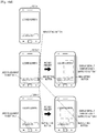
- FIG. 8A illustrates an icon layout on a home screen and an initial operation according to an exemplary embodiment of the present invention.
- a home screen with icons arranged with the same size and interval is displayed on an existing display area 805.
- the home screen with the icons rearranged at new coordinates is displayed in a current comfort zone 810.
- the rearranged icons have the original size and interval.
- the comfort zone 810 is defined as an area touchable by a thumb of a one-hand user, the comfort zone 810 has a relatively small available area for icons as compared to the existing display area 805. Accordingly, as the icons are rearranged with the original size and interval in the comfort zone 810, a part of the rearranged icons may be moved to the next page.
- the user may adjust the sizes and intervals of the icons so that all of the icons may be displayed within the current page or only frequently used icons may be displayed on the home screen according to the user's preferences.
- the rearranged icons may be displayed on the current and next pages according to their use frequencies. While a page number 807 indicating the current page is written horizontally in the existing display area 805, the present invention is not limited thereto, and the page number 807 may be written according to a thumb moving direction in the comfort zone 810, as indicated by reference numeral 812.
- the user determines to adjust the sizes, intervals, and layout of the icons after viewing the icons displayed in the comfort zone 810, the user first selects icons to be adjusted from among the displayed icons. For the convenience of description, the selected icons are shown as shaded in the comfort zone 810. For example, the user may select an intended icon by clicking on the icon once or dragging the icon without detaching a hand from the icon, then a selection area 814 including selected icons is displayed. When the user touches a part of the selection area 814 or one of the selected icons, the home screen of the comfort zone 810 displays a window for a specific setting of rearrangement of the selected icons.
- FIG. 8B illustrates screens displayed for a specific setting of rearranging selected icons according to an exemplary embodiment of the present invention.
- a first screen 820 displays a pop-up window 822 overlapped over the selection area 814, for a specific setting of rearrangement.
- the first screen 820 which is rendered transparent, may be displayed simultaneously with the selection area 814.
- the icons of the selection area 814 may be displayed as a preview reflecting the user input.
- icons rearranged according to the setting indicated by the user input may be displayed, simultaneously with disappearance of the pop-up window 822.
- a second screen 830 displays a rearrangement setting menu independently of the existing display area 810.
- the rearrangement setting menu provides menu items with which to select increase or decrease in the size and interval of a selected icon.
- a button with which to adjust the degree of increase or decrease such as a rate button may further be displayed.
- the rearrangement setting menu provides Yes and No buttons for 'manual selection' so that the user may manually rearrange the positions or intervals of selected icons.
- a reference icon 842 or 844 may be selected according to a user input, such as click or touch, on the icon 842 or 844 in the third screen 840.
- a user input such as click or touch
- the sizes and intervals of the icons in the selection area 814 may be adjusted uniformly.
- the reference icon 842 or 844 may be scaled down or up by dragging the reference icon 842 inward or dragging the reference icon 844 outward in accordance with an intended size.
- an area corresponding the distance between icons may be adjusted by touching or clicking on the area and then dragging the area inward or outward according to an intended interval.
- each individual icon within the selection area 814 may be adjusted by dragging a touch or click on the icon according to an intended size or interval, rather than the icons of a selected area 816 which are adjusted in size and interval at one time by setting a reference icon.
- FIG. 9A illustrates additional UIs available for rearrangement of selected icons according to an exemplary embodiment of the present invention.
- a screen 900 displays additional UIs, which may be icons, buttons, or similar graphical displays, that are not provided in the existing display area 805 of FIG. 8A , for example, a toggle button 902, a back button 904, and a home button 906.
- the toggle button 902 is a UI that receives a command to set a comfort zone 912 displayed on the screen 900 as a frequently used page, or The toggle button 902 is able to use as a UI that receives a command to convert between the existing display area 805 and the comfort zone 810. While not shown in FIG. 9A , it is assumed that the comfort zone 912 displays icons rearranged in the manner described before with reference to FIGS. 8A and 8B .
- the back button 904 is for receiving a command to return to the previous screen.
- the home button 906 is for receiving a command to return to a home screen , the comfort zone 810, by way of example.
- icons are displayed as an exemplary content type in a display area for the convenience of description, the present invention is not limited thereto, and the present exemplary embodiment is applicable to many other types of content.
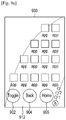
- FIG. 9B illustrates additional UIs available on a content basis for rearrangement of selected icons according to an exemplary embodiment of the present invention.
- a first screen 920 displays additional UIs 922 including a toggle button, a back button, and a home button, when lists are rearranged as content in a comfort zone.
- a second screen 930 displays additional UIs 932 including a toggle button, a back button, and a home button, when multimedia, for example, videos, are rearranged as content in a comfort zone.
- UIs 934 may further be provided for the user to view the videos.
- the UIs 934 may include a play button, a pause button, a stop button, and the like.
- a third screen 940 displays additional UIs 942 including a toggle button, a back button, and a home button, when a keyboard is rearranged as content in a comfort zone.
- FIG. 10A is a flowchart illustrating an operation of a comfort zone decider in a touch screen control apparatus according to another exemplary embodiment of the present invention.
- the comfort zone decider 310 may control the display unit 305 to provide a comfort zone selection screen including, for example, at least one of a button that requests a touch input request screen (not shown) to determine a comfort zone and a button that selects preset default comfort zones in step 1000.
- the comfort zone selection screen may be, for example, a locked home screen or an additional screen requesting a user touch input. Whether the locked home screen or the additional screen requesting a user touch input is provided as the comfort zone selection screen and the touch input request screen on the display unit 305 may be preset by the user or by default by the manufacturer.
- the comfort zone decider 310 may set a comfort zone based on a user touch input that unlocks the locked screen according to the afore-described exemplary embodiment of the present invention.
- FIG. 10B illustrates a comfort zone selection screen according to another exemplary embodiment of the present invention.
- a comfort zone selection screen 1100 may display a comfort zone selection list on the touch screen corresponding to the display unit 305.
- the comfort zone selection list may include a menu 'touch input request screen' and a menu 'default comfort zones' as illustrated in FIG. 10B . These menus are displayed as buttons so that the user may select a menu by touching a button corresponding to the menu.
- FIG. 10C illustrates default comfort zones pre-stored in the touch screen control apparatus according to an exemplary embodiment of the present invention.
- default comfort zones are defined based on the fan-shaped area 200 illustrated in FIG. 2 corresponding to a range touchable by a thumb on the touch screen.
- the default comfort zones may be preset by the user or by default by the manufacturer according to the above described exemplary embodiments of the present invention.
- the default comfort zones may be configured by adding an area outside the fan-shaped area 200 or excluding a part from the fan-shaped area 200. Specifically, a first default comfort zone 1102 is fully included in the fan-shaped area 200. A second default comfort zone 1104 is shaped into a rectangle partially overlapped with the fan-shaped area 200. A third default comfort zone 1106 is a part of the fan-shaped area 200, particularly except for a thumb-untouchable area other than a shaded area of the fan-shaped area 200.
- a fourth default comfort zone 1108 is configured by removing the non-shaded area of the fan-shaped area 200, untouchable by the thumb of the user.
- a fifth default comfort zone 1110 is shaped into a rectangle having a rectangular non-shaded area of the fan-shaped area 200 being removed.
- a sixth default comfort zone 1112 is a semicircle having the center point on the right side of the existing display area 1101, fully included in the fan-shaped area 200.
- the comfort zone decider 310 determines a menu selected from the comfort zone selection list according to a user touch input in step 1005. If the menu requesting a touch input request screen has been selected, then the comfort zone decider 310 performs steps 1010 through 1025 in the same manner as steps 410 through 425 of FIG. 4 . Thus steps 1010 through 1025 will not be described herein to avoid redundancy.
- the comfort zone decider 310 controls the display unit 305 to display a screen, hereinafter, referred to as a 'default comfort zone selection screen' used to select a specific default comfort zone from among pre-stored default comfort zones in step 1030 and proceeds to step 1035.
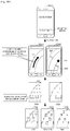
- FIG. 10D illustrates a default comfort zone selection screen according to an exemplary embodiment of the present invention.
- the default comfort zone selection screen may also be a locked home screen or an additional screen requesting a touch input.
- a first default comfort zone selection screen 1200a may display buttons that are one-to-one mapped to pre-stored default comfort zones, hereinafter, referred to as 'default comfort zone selection buttons' and a button used to configure a new default comfort zone, hereinafter, referred to as a 'new setting button' at the bottom of the display area.
- the default comfort zone selection buttons are shown as numerals in FIG. 10D .
- the comfort zone decider 310 determines whether a user touch input is detected. Upon detecting a user touch input to a default comfort zone selection button in the menus provided on the default comfort zone selection screen in step 1035, then, in step 1040, the comfort zone decider 310 controls the display unit 305 to display a preview of a comfort zone mapped to the default comfort zone selection button. In an exemplary embodiment of the present invention, upon sensing a short touch or a single click on a default comfort zone selection button, the comfort zone decider 310 provides a preview of a default comfort zone corresponding to the default comfort zone selection button. Upon sensing a long touch or double clicks on a default comfort zone selection button, the comfort zone decider 310 determines a default comfort zone mapped to the default comfort zone selection button as a current default comfort zone.
- a user touch input to button 1 is sensed in a second default comfort zone selection screen 1200b-1. If the user touch input to button 1 is a short touch or single click, the second default comfort zone selection screen 1200b-1 provides a preview of a default comfort zone corresponding to button 1.
- a user touch input to button 2 is sensed in a third default comfort zone selection screen 1200c-1. If the user touch input to button 2 is a short touch or single click, then the third default comfort zone selection screen 1200c-1 provides a preview of a default comfort zone corresponding to button 2.
- step 1045 the comfort zone decider 310 determines whether a user touch input being a long touch or double clicks on a specific default comfort zone selection button is detected. If a user touch input has not been detected, in step 1045, in the form of a long touch or double clicks on a specific default comfort zone selection button, then the comfort zone decider 310 awaits detection of a user touch input.
- the comfort zone decider 310 determines a default comfort zone mapped to the button as a current default comfort zone in step 1050. Subsequently, the comfort zone decider 310 performs an adjustment operation on the current default comfort zone in steps 1015 through 1025. As noted above, steps 1015 through 1025 are the same as steps 415 through 425 of FIG. 4 and thus will not be described herein.
- the comfort zone decider 310 may control the display unit 305 to provide a touch input request screen.
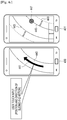
- FIG. 10E illustrates a case where the new setting button is selected on a default comfort zone selection screen according to an exemplary embodiment of the present invention.
- a user touch input to the new setting button is sensed on a fourth default comfort zone selection screen 1200d-1.
- the fourth default comfort zone selection screen 1200d-1 provides a touch input request screen 1200d-2 to allow the user to set a new comfort zone.
- a direction 1210 in which the user slides or drags the thumb across the touch screen is sensed.
- the comfort zone decider 310 may estimate a touchable area based on the touched area and the sensed sliding or dragging direction 1210 and may determine the estimated touchable area as a new comfort zone.
- the comfort zone decider 310 may control the display unit 305 to display the new comfort zone so that the user may identify the new comfort zone. While not shown, the display unit 305 may display only the boundaries or full area of the determined new comfort zone.
- the comfort zone decider 310 determines whether the new comfort zone is to be adjusted and performs an adjustment operation based on the determination in steps 1015 through 1025. Specifically, as done in step 415 of FIG. 4 , the comfort zone decider 310 controls the display unit 305 to provide a screen asking the user whether to maintain or adjust the new comfort zone and receives a user input in response to the question. Whether the asking screen is to be provided may be preset by default in the digital portable terminal by the manufacturer or may be set freely by the one-hand user during initial setting of the digital portable terminal. For example, the asking screen may prompt the user to make a choice between maintenance and adjustment of the determined comfort zone.
- the comfort zone decider 310 determines the new comfort zone as a current comfort zone and provides information about the current comfort zone to the UI layout converter 320.
- the comfort zone decider 310 controls the display unit 305 to provide a touch input request screen 1200d-3 for comfort zone adjustment. Then the display unit 305 displays boundaries 1225 of the new comfort zone on the touch input request screen 1200d-3.
- the one-hand user clicks a point 1220 for a predetermined amount of time on a boundary 1225 of the current comfort zone, then the clicked boundary 1225 is placed in an adjustable state. The user may now scale up or down the current comfort zone by dragging the clicked boundary 1225 to an intended position.
- a click and dragging scheme is used to adjust a comfort zone in the above exemplary embodiment
- the present invention is not limited thereto, and an operation of selecting a boundary of the comfort zone and thus placing the boundary in an adjustable state and an operation of adjusting the boundary may be performed by many other preset inputs.
- the boundary may be adjusted by a predetermined extent at each click or each time a predetermined motion is recognized.
- the comfort zone decider 310 adjusts the size of content to be arranged in the new comfort zone and stores the size-adjusted content.
- the size of the content may be increased or decreased according to preset size levels, for example, large, standard, and small as indicated by reference numerals 1304a, 1304b, and 1304c. While not shown, the content to be displayed in the new comfort zone may be rearranged according to the user's preferences and the use frequencies of the content.
- a range to which a comfort zone set according to the above-described exemplary embodiments is applied may be set additionally.
- a 'comfort zone apply setting' menu may be added to a basic setting menu in order to set a range to which a comfort zone is applied in a user device.
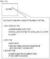
- FIG. 11A illustrates menu items of a comfort zone apply setting menu added to a setting menu of a user device according to an exemplary embodiment of the present invention.
- the comfort zone apply setting menu may include, for example, an 'Apply Range setting' menu item, an 'Apply Time' menu item, and a 'Recovery Time' menu item.
- the 'Apply Range Setting' menu item may include an On/Off button to determine whether to use icons provided on a home screen, an On/Off button to determine whether to apply a specific UI such as an afore-described application control UI, and an On/Off button to determine whether to use all screens and icons available to the user device.
- the 'Apply Time' menu item may impose an additional condition that only when the On button indicating that all screens and icons available to the user device are always used is selected and a predetermined motion is made as a user touch input, a comfort zone is applied.
- the predetermined motion may include a sliding, a drag, a long touch on an area, and the like.
- FIG. 11B illustrates a case where if 'Always On'is selected in a 'Apply Time' menu item of the comfort zone usage setting menu, a comfort zone is applied only when a touch input slides across a touch screen according to an exemplary embodiment of the present invention.
- 'Apply Time' is set in the setting menu in such a manner that the moment a sliding motion is made in any direction in an existing display area 1410, a comfort zone is effective and a target icon 1402 of a one-hand user is outside of the movement range of a thumb of the one-hand user in the existing display area 1410. If the one-hand user slides the thumb across a part of the display area 1410 in any direction, then the display area 1410 is switched to a current default comfort zone 1420 preset according to the above described exemplary embodiments of the present invention. As the target icon 1402 is moved within the current default zone 1420, then the one-hand user may touch the target icon 1402 with the thumb.
- the 'Recovery Time' may include a menu item that automatically switches a locked screen to a comfort zone, each time the locked screen is unlocked.
- the comfort zone may be set according to the first exemplary embodiment of the present invention.
- a recovery time may be set, for example, by making a sliding motion across a screen displaying the comfort zone 1420, reversely to a sliding direction used to switch to the comfort zone 1420.
- additional UIs are provided to a user in the above manner, the user may readily use or set icons within a comfort zone of a display area. Therefore, user experience is enhanced.
- a partial touchable area is set in the display area of a touch screen and UIs are rearranged in the partial touchable area by adjusting the sizes and positions of the UIs in a digital portable terminal, a user experience is enhanced. Furthermore, additional UIs are provided to use the rearranged UIs in the partial touchable area, further enhancing user experience.
- the exemplary embodiments of the present disclosure as described above typically involve the processing of input data and the generation of output data to some extent.
- This input data processing and output data generation may be implemented in hardware or software in combination with hardware.
- specific electronic components may be employed in a mobile device or similar or related circuitry for implementing the functions associated with the exemplary embodiments of the present invention as described above.
- one or more processors operating in accordance with stored instructions may implement the functions associated with the exemplary embodiments of the present invention as described above. If such is the case, it is within the scope of the present disclosure that such instructions may be stored on one or more processor readable mediums.
- processor readable mediums examples include Read-Only Memory (ROM), Random-Access Memory (RAM), CD-ROMs, magnetic tapes, floppy disks, and optical data storage devices.
- ROM Read-Only Memory
- RAM Random-Access Memory
- CD-ROMs Compact Disc-ROMs
- magnetic tapes magnetic tapes
- floppy disks optical data storage devices.
- the processor readable mediums can also be distributed over network coupled computer systems so that the instructions are stored and executed in a distributed fashion.
- functional computer programs, instructions, and instruction segments for accomplishing the present invention can be easily construed by programmers skilled in the art to which the present invention pertains.
Claims (14)
- Verfahren zum Bereitstellen von Benutzerschnittstellen, UIs, auf einem Touchscreen, wobei das Verfahren umfasst:Identifizieren eines Bereichs, der auf dem Touchscreen durch eine Benutzereingabe berührt wird;Anzeigen eines Menüpunkts in einem Grundeinstellungsmenü, das in dem elektronischen Gerät voreingestellt ist, wobei der Menüpunkt verwendet wird, um eine Neuanordnung von UIs auszuwählen, die in einem Anzeigebereich (550, 700, 805, 1101, 1410) des Touchscreens in einem benutzerberührbaren Teilbereich (205, 560, 712, 722, 732, 810, 912) angeordnet sind; undAnzeigen eines neu angeordneten Bildschirms, der die in dem benutzerberührbaren Teilbereich (205, 560, 712, 722, 732, 810, 912) auf dem Touchscreen neu angeordneten UIs anzeigt, als Reaktion auf das Identifizieren des benutzerberührbaren Teilbereichs (205, 560, 712, 722, 732, 810, 912) basierend auf dem identifizierten Bereich,wobei der Menüpunkt mindestens eines von einem Untermenü zum Einstellen eines Anwendungsbereichs des neu angeordneten Bildschirms, einem Untermenü zum Einstellen einer Anwendungszeit der Neuanordnung der UIs in dem benutzerberührbaren Teilbereich und einem Untermenü zum Einstellen einer Wiederherstellungszeit zum Zurückspringen des neu angeordneten Bildschirms zu einem ursprünglichen Bildschirm umfasst; undwobei die UIs Tasten einer Tastatur umfassen.
- Verfahren nach Anspruch 1, ferner umfassend, wenn das Untermenü zum Einstellen der Anwendungszeit auf Bildschirmentsperrung eingestellt ist, das Anzeigen eines benutzerberührbaren Teilbereichsauswahlbildschirms (1200a, 1200b-1, 1200c-1) beim Erfassen einer Benutzerberührungseingabe, die das Entsperren des Bildschirms anfordert,
wobei der benutzerberührbare Teilbereichsauswahlbildschirm (1200a, 1200b-1, 1200c-1) mindestens einen von einem ersten Auswahlelement zum Auswählen von vorgespeicherten vorgegebenen benutzerberührbaren Teilbereichen (205, 560, 712, 722, 732, 810, 912) und einem zweiten Auswahlelement zum Anzeigen eines Berührungseingabe-Anforderungsbildschirms (1200d-1, 1200d-3) umfasst, der konfiguriert ist, um einen benutzerberührbaren Teilbereich (205, 560, 712, 722, 732, 810, 912) gemäß einer Benutzerberührungseingabe einzustellen. - Verfahren nach Anspruch 2, ferner umfassend:Anzeigen eines Bildschirms, der erste Auswahlschaltflächen, die den vorgegebenen benutzerberührbaren Teilbereichen (205, 560, 712, 722, 732, 810, 912) zugeordnet sind, und eine zweite Auswahlschaltfläche zum Einstellen eines neuen benutzerberührbaren Teilbereichs (205, 560, 712, 722, 732, 810, 912) umfasst, beim Erfassen einer Benutzerberührungseingabe, die das zweite Auswahlelement auswählt; undAnzeigen einer Vorschau eines vorgegebenen benutzerberührbaren Teilbereichs (205, 560, 712, 722, 732, 810, 912), der einer ersten Auswahlschaltfläche entspricht, beim Erfassen einer Benutzerberührungseingabe an der ersten Auswahlschaltfläche und Anzeigen eines Berührungseingabe-Anforderungsbildschirms (1200d-1, 1200d-3) zum Einstellen eines benutzerberührbaren Teilbereichs (205, 560, 712, 722, 732, 810, 912) beim Erfassen einer Benutzerberührungseingabe an der zweiten Auswahlschaltfläche.
- Verfahren nach Anspruch 2, wobei, wenn der benutzerberührbare Teilbereichsauswahlbildschirm (1200a, 1200b-1, 1200c-1) nur das erste Auswahlelement anzeigt, das erste Auswahlelement ein Untermenü, das die Auswahl der vorgegebenen benutzerberührbaren Bereiche anzeigt, und ein Untermenü, das die Nichtauswahl der vorgegebenen benutzerberührbaren Bereiche anzeigt, umfasst.
- Verfahren nach Anspruch 4, ferner umfassend:Anzeigen eines Bildschirms, der Grenzen (443, 445, 1225) eines benutzerberührbaren Teilbereichs (205, 560, 712, 722, 732, 810, 912) umfasst, als Reaktion auf die Benutzerberührungseingabe, die eine Bildschirmentsperrung anfordert, beim Erfassen einer Benutzerberührungseingabe an dem Untermenü, das die Nichtauswahl der vorgegebenen benutzerberührbaren Teilbereiche (205, 560, 712, 722, 732, 810, 912) anzeigt;Anpassen einer Grenze (443, 445, 1225) des benutzerberührbaren Teilbereichs (205, 560, 712, 722, 732, 810, 912) gemäß einer Benutzerberührungseingabe an der Grenze (443, 445, 1225) beim Erfassen der Benutzerberührungseingabe an der Grenze (443, 445, 1225); undAnzeigen eines neu angeordneten Bildschirms, der die UIs umfasst, die in dem benutzerberührbaren Bereich (205, 560, 712, 722, 732, 810, 912) mit der angepassten Grenze (443, 445, 1225) neu angeordnet sind.
- Verfahren nach Anspruch 5, wobei das Anzeigen des neu angeordneten Bildschirms, der die UIs umfasst, die in dem benutzerberührbaren Teilbereich (205, 560, 712, 722, 732, 810, 912) mit der angepassten Grenze (443, 445, 1225) neu angeordnet sind, umfasst:Identifizieren einer Zuordnungsbeziehung zwischen Koordinaten des Anzeigebereichs (550, 700, 805, 1101, 1410) und Koordinaten des grenzangepassten benutzerberührbaren Teilbereichs (205, 560, 712, 722, 732, 810, 912); undNeuanordnen der im Anzeigebereich (550, 700, 805, 1101, 1410) angeordneten UIs im grenzangepassten benutzerberührbaren Teilbereich (205, 560, 712, 722, 732, 810, 912) basierend auf der identifizierten Zuordnungsbeziehung.
- Verfahren nach Anspruch 5, wobei das Anzeigen des neu angeordneten Bildschirms, der die UIs umfasst, die in dem benutzerberührbaren Teilbereich (205, 560, 712, 722, 732, 810, 912) mit der angepassten Grenze (443, 445, 1225) neu angeordnet sind, umfasst:Anzeigen eines Bildschirms, der mindestens eine der neu angeordneten UIs getrennt von den anderen UIs umfasst, beim Erfassen einer Benutzerberührungseingabe an der mindestens einen der neu angeordneten UIs;Anzeigen eines Bildschirms, der ein Menü umfasst, um eine Größe und ein Intervall der mindestens einen der neu angeordneten UIs einzustellen; undAnzeigen eines Bildschirms, der die mindestens eine der neu angeordneten UIs gemäß einer Benutzerberührungseingabe an einem Befehl umfasst, der in dem Menü enthalten ist, beim Erfassen der Benutzerberührungseingabe an dem Befehl.
- Elektronisches Gerät zum Bereitstellen von Benutzerschnittstellen, UIs, wobei das elektronische Gerät umfasst:einen Touchscreen (305); undmindestens einen Prozessor, der konfiguriert ist, um:einen durch eine Benutzereingabe auf dem Touchscreen berührten Bereich zu identifizieren, einen Menüpunkt in einem Grundeinstellungsmenü anzuzeigen, das in dem elektronischen Gerät voreingestellt ist, wobei der Menüpunkt verwendet wird, um eine Neuanordnung von UIs auszuwählen, die in einem Anzeigebereich (550, 700, 805, 1101, 1410) des Touchscreens in einem benutzerberührbaren Teilbereich (560, 712, 722, 732, 810, 912) angeordnet sind; undden Touchscreen (305) zu steuern, um einen neu angeordneten Bildschirm anzuzeigen, der die in dem benutzerberührbaren Teilbereich (205, 560, 712, 722, 732, 810, 912) neuangeordneten UIs anzeigt, als Reaktion auf das Identifizieren des benutzerberührbaren Teilbereichs (205, 560, 712, 722, 732, 810, 912) basierend auf dem identifizierten Bereich,wobei der Menüpunkt mindestens einen von einem Untermenü zum Einstellen eines Anwendungsbereichs des neu angeordneten Bildschirms, einem Untermenü zum Einstellen einer Anwendungszeit der Neuanordnung der UIs in dem benutzerberührbaren Teilbereich (205, 560, 712, 722, 732, 810, 912) und einem Untermenü zum Einstellen einer Wiederherstellungszeit zum Zurückspringen des neu angeordneten Bildschirms zu einem ursprünglichen Bildschirm umfasst; undwobei die UIs Tasten einer Tastatur umfassen.
- Elektronisches Gerät nach Anspruch 8, wobei, wenn das Untermenü zum Einstellen der Anwendungszeit auf Bildschirmentsperrung eingestellt ist, der mindestens eine Prozessor den Touchscreen (305) steuert, um einen benutzerberührbaren Teilbereichsauswahlbildschirm (1200a, 1200b-1, 1200c-1) beim Erfassen einer Benutzerberührungseingabe anzuzeigen, die das Entsperren des Bildschirms anfordert,
wobei der benutzerberührbare Teilbereichsauswahlbildschirm (1200a, 1200b-1, 1200c-1) mindestens einen von einem ersten Auswahlelement zum Auswählen von vorgespeicherten vorgegebenen benutzerberührbaren Teilbereichen (205, 560, 712, 722, 732, 810, 912) und einem zweiten Auswahlelement zum Anzeigen eines Berührungseingabe-Anforderungsbildschirms (1200d-1, 1200d-3) umfasst, der konfiguriert ist, um einen benutzerberührbaren Teilbereich (205, 560, 712, 722, 732, 810, 912) gemäß einer Benutzerberührungseingabe einzustellen. - Elektronisches Gerät nach Anspruch 9, wobei beim Erfassen einer Benutzerberührungseingabe, die das zweite Auswahlelement auswählt, der mindestens eine Prozessor den Touchscreen (305) steuert, um einen Bildschirm anzuzeigen, der erste Auswahlschaltflächen, die den vorgegebenen benutzerberührbaren Teilbereichen (205, 560, 712, 722, 732, 810, 912) zugeordnet sind, und eine zweite Auswahlschaltfläche zum Einstellen eines neuen benutzerberührbaren Teilbereichs (205, 560, 712, 722, 732, 810, 912) umfasst, und
wobei beim Erfassen einer Benutzerberührungseingabe an einer ersten Auswahlschaltfläche der mindestens eine Prozessor den Touchscreen (305) steuert, um eine Vorschau eines vorgegebenen benutzerberührbaren Teilbereichs (205, 560, 712, 722, 732, 810, 912) anzuzeigen, der der ersten Auswahlschaltfläche entspricht, und beim Erfassen einer Benutzerberührungseingabe an der zweiten Auswahlschaltfläche der mindestens eine Prozessor den Touchscreen (305) steuert, um einen Berührungseingabe-Anforderungsbildschirm (1200d-1, 1200d-3) zum Einstellen eines benutzerberührbaren Teilbereichs (205, 560, 712, 722, 732, 810, 912) anzuzeigen. - Elektronisches Gerät nach Anspruch 9, wobei, wenn der benutzerberührbare Teilbereichsauswahlbildschirm nur das erste Auswahlelement bereitstellt, das erste Auswahlelement ein Untermenü, das die Auswahl der vorgegebenen benutzerberührbaren Bereiche (205, 560, 712, 722, 732, 810, 912) anzeigt, und ein Untermenü, das die Nichtauswahl der vorgegebenen benutzerberührbaren Bereiche (205, 560, 712, 722, 732, 810, 912) anzeigt, umfasst.
- Elektronisches Gerät nach Anspruch 11, wobei der mindestens eine Prozessor den Touchscreen (305) steuert, um einen Bildschirm anzuzeigen, der Grenzen (443, 445, 1225) eines benutzerberührbaren Teilbereichs (205, 560, 712, 722, 732, 810, 912) umfasst, als Reaktion auf die Benutzerberührungseingabe, die eine Bildschirmentsperrung anfordert, beim Erfassen einer Benutzerberührungseingabe an dem Untermenü, das die Nichtauswahl der vorgegebenen benutzerberührbaren Teilbereiche (205, 560, 712, 722, 732, 810, 912) anzeigt;
wobei der mindestens eine Prozessor eine Grenze (443, 445, 1225) des benutzerberührbaren Teilbereichs (205, 560, 712, 722, 732, 810, 912) gemäß einer Benutzerberührungseingabe an der Grenze (443, 445, 1225) beim Erfassen der Benutzerberührungseingabe an der Grenze (443, 445, 1225) anpasst; und
wobei der mindestens eine Prozessor den Touchscreen (305) steuert, um einen neu angeordneten Bildschirm anzuzeigen, der die UIs anzeigt, die in dem benutzerberührbaren Bereich (205, 560, 712, 722, 732, 810, 912) mit der angepassten Grenze (443, 445, 1225) angeordnet sind. - Elektronisches Gerät nach Anspruch 12, wobei der mindestens eine Prozessor eine Zuordnungsbeziehung zwischen Koordinaten des Anzeigebereichs (550, 700, 805, 1101, 1410) und Koordinaten des grenzangepassten benutzerberührbaren Teilbereichs (205, 560, 712, 722, 732, 810, 912) identifiziert und die im Anzeigebereich (550, 700, 805, 1101, 1410) angeordneten UIs in dem grenzangepassten benutzerberührbaren Teilbereich (205, 560, 712, 722, 732, 810, 912) basierend auf der identifizierten Zuordnungsbeziehung neu anordnet.
- Elektronisches Gerät nach Anspruch 12, wobei der mindestens eine Prozessor den Touchscreen (305) steuert, um einen Bildschirm anzuzeigen, der mindestens eine der neu angeordneten UIs umfasst, die sich von den anderen UIs unterscheidet, beim Erfassen einer Benutzerberührungseingabe an der mindestens einen der neu angeordneten UIs,
wobei der mindestens eine Prozessor den Touchscreen (305) steuert, um einen Bildschirm anzuzeigen, der ein Menü zum Einstellen einer Größe und eines Intervalls für die mindestens eine der neu angeordneten UIs umfasst, und
wobei der mindestens eine Prozessor den Touchscreen (305) steuert, um einen Bildschirm anzuzeigen, der die mindestens eine der neu angeordneten UIs gemäß einer Benutzerberührungseingabe an einem Befehl umfasst, der in dem Menü enthalten ist, beim Erfassen der Benutzerberührungseingabe an dem Befehl.
Applications Claiming Priority (2)
| Application Number | Priority Date | Filing Date | Title |
|---|---|---|---|
| KR20120053799 | 2012-05-21 | ||
| PCT/KR2013/004458 WO2013176472A1 (en) | 2012-05-21 | 2013-05-21 | Method and apparatus of controlling user interface using touch screen |
Publications (3)
| Publication Number | Publication Date |
|---|---|
| EP2852882A1 EP2852882A1 (de) | 2015-04-01 |
| EP2852882A4 EP2852882A4 (de) | 2016-01-27 |
| EP2852882B1 true EP2852882B1 (de) | 2021-08-18 |
Family
ID=49580925
Family Applications (1)
| Application Number | Title | Priority Date | Filing Date |
|---|---|---|---|
| EP13793991.4A Active EP2852882B1 (de) | 2012-05-21 | 2013-05-21 | Verfahren und vorrichtung zur steuerung einer benutzerschnittstelle mittels eines berührungsbildschirms |
Country Status (6)
| Country | Link |
|---|---|
| US (2) | US10338705B2 (de) |
| EP (1) | EP2852882B1 (de) |
| JP (1) | JP6279553B2 (de) |
| KR (1) | KR102094695B1 (de) |
| CN (1) | CN104321736B (de) |
| WO (1) | WO2013176472A1 (de) |
Families Citing this family (58)
| Publication number | Priority date | Publication date | Assignee | Title |
|---|---|---|---|---|
| US10048860B2 (en) | 2006-04-06 | 2018-08-14 | Google Technology Holdings LLC | Method and apparatus for user interface adaptation |
| KR101340703B1 (ko) | 2011-11-25 | 2013-12-12 | 삼성전자주식회사 | 휴대단말기의 키패드 배치장치 및 방법 |
| US9367085B2 (en) | 2012-01-26 | 2016-06-14 | Google Technology Holdings LLC | Portable electronic device and method for controlling operation thereof taking into account which limb possesses the electronic device |
| CN108031501B (zh) * | 2012-02-13 | 2021-04-23 | 恩姆菲舍尔科技公司 | 电子吸液管 |
| KR101979666B1 (ko) | 2012-05-15 | 2019-05-17 | 삼성전자 주식회사 | 표시부에 출력되는 입력 영역 운용 방법 및 이를 지원하는 단말기 |
| JP5866027B2 (ja) * | 2012-10-19 | 2016-02-17 | 三菱電機株式会社 | 情報処理装置、情報端末、情報処理システムおよびキャリブレーション方法 |
| KR20140070745A (ko) * | 2012-11-26 | 2014-06-11 | 삼성전자주식회사 | 디스플레이 장치 및 이의 구동 방법 |
| KR20140087731A (ko) * | 2012-12-31 | 2014-07-09 | 엘지전자 주식회사 | 포터블 디바이스 및 사용자 인터페이스 제어 방법 |
| US10691291B2 (en) * | 2013-05-24 | 2020-06-23 | Samsung Electronics Co., Ltd. | Method and apparatus for displaying picture on portable device |
| CN104281378A (zh) * | 2013-07-05 | 2015-01-14 | 深圳富泰宏精密工业有限公司 | 移动装置单手掌控处理方法及系统 |
| GB2516029A (en) * | 2013-07-08 | 2015-01-14 | Ibm | Touchscreen keyboard |
| KR102156140B1 (ko) * | 2013-07-19 | 2020-09-15 | 엘지전자 주식회사 | 이동 단말기 및 이의 제어방법 |
| TWI608407B (zh) * | 2013-11-27 | 2017-12-11 | 緯創資通股份有限公司 | 觸控裝置及其控制方法 |
| CN104750400B (zh) * | 2013-12-27 | 2017-12-15 | 华为技术有限公司 | 终端界面的优化操作方法和装置 |
| US20150186011A1 (en) * | 2013-12-30 | 2015-07-02 | Samsung Electronics Co., Ltd. | Apparatus and method for interacting with items on a portable terminal |
| EP3097473A4 (de) * | 2014-01-20 | 2017-09-13 | Samsung Electronics Co., Ltd. | Benutzerschnittstelle für berührungsempfindliche vorrichtungen |
| KR20150135980A (ko) * | 2014-05-26 | 2015-12-04 | 삼성전자주식회사 | 디스플레이 제어 방법 및 전자 장치 |
| CN105204756A (zh) | 2014-06-30 | 2015-12-30 | 阿尔卡特朗讯 | 一种用于操作触摸屏设备的屏幕的方法与设备 |
| KR102255302B1 (ko) * | 2014-07-24 | 2021-05-24 | 삼성전자주식회사 | 투과 및 반사영역을 선택적으로 만들 수 있는 전기변색패널 및 그 동작방법과 그러한 전기변색패널을 포함하는 표시장치와 동작방법 |
| US9971496B2 (en) | 2014-08-04 | 2018-05-15 | Google Technology Holdings LLC | Method and apparatus for adjusting a graphical user interface on an electronic device |
| WO2016020807A1 (en) * | 2014-08-04 | 2016-02-11 | Realitygate (Pty) Ltd | Display and interaction method in a user interface |
| JP6275584B2 (ja) * | 2014-08-05 | 2018-02-07 | シャープ株式会社 | 電子機器 |
| US10152227B2 (en) * | 2014-08-26 | 2018-12-11 | International Business Machines Corporation | Free form user-designed single-handed touchscreen keyboard |
| JP5937278B1 (ja) * | 2014-09-04 | 2016-06-22 | ヤマザキマザック株式会社 | メニュー表示機能を有する装置 |
| US10671275B2 (en) * | 2014-09-04 | 2020-06-02 | Apple Inc. | User interfaces for improving single-handed operation of devices |
| US20160162149A1 (en) * | 2014-12-05 | 2016-06-09 | Htc Corporation | Mobile electronic device, method for displaying user interface, and recording medium thereof |
| US9898126B2 (en) | 2015-03-31 | 2018-02-20 | Toshiba Global Commerce Solutions Holdings Corporation | User defined active zones for touch screen displays on hand held device |
| US9874952B2 (en) | 2015-06-11 | 2018-01-23 | Honda Motor Co., Ltd. | Vehicle user interface (UI) management |
| KR20170002051A (ko) * | 2015-06-29 | 2017-01-06 | 삼성전자주식회사 | 한 손 조작 사용자 인터페이스 구현 방법 및 이를 수행하는 전자 장치 |
| US10248311B2 (en) | 2015-07-06 | 2019-04-02 | Samsung Electronics Co., Ltd. | Electronic device supporting virtual keyboard and method for configuring the virtual keyboard |
| CN105117056B (zh) * | 2015-08-17 | 2019-02-01 | 青岛海信移动通信技术股份有限公司 | 一种操作触摸屏的方法和设备 |
| WO2017039125A1 (en) * | 2015-08-28 | 2017-03-09 | Samsung Electronics Co., Ltd. | Electronic device and operating method of the same |
| US20170060398A1 (en) * | 2015-09-02 | 2017-03-02 | Sap Se | Dynamic display of user interface elements in hand-held devices |
| KR20170029180A (ko) * | 2015-09-07 | 2017-03-15 | 현대자동차주식회사 | 차량, 및 그 제어방법 |
| JP6344355B2 (ja) * | 2015-09-28 | 2018-06-20 | キヤノンマーケティングジャパン株式会社 | 電子端末、及びその制御方法とプログラム |
| CN105487776A (zh) * | 2015-11-30 | 2016-04-13 | 上海斐讯数据通信技术有限公司 | 一种电子设备及其应用的操作方法 |
| KR20170103379A (ko) * | 2016-03-04 | 2017-09-13 | 주식회사 이노스파크 | 반응형 유저인터페이스 제공 방법 |
| US10079972B2 (en) | 2016-03-10 | 2018-09-18 | Mediatek Inc. | Method for controlling graphical user interface of camera application |
| CN106201172B (zh) * | 2016-06-24 | 2020-09-01 | 广州视睿电子科技有限公司 | 一种触屏终端的画布显示方法及装置 |
| KR102629409B1 (ko) * | 2016-11-11 | 2024-01-26 | 삼성전자주식회사 | 객체 정보를 제공하기 위한 방법 및 그 전자 장치 |
| US10591878B2 (en) | 2016-12-09 | 2020-03-17 | Ademco Inc. | Providing integrative comfort in a structure |
| CN107257395B (zh) * | 2017-04-27 | 2019-10-08 | 努比亚技术有限公司 | 一种屏幕调整方法及终端 |
| US20190026120A1 (en) * | 2017-07-21 | 2019-01-24 | International Business Machines Corporation | Customizing mobile device operation based on touch points |
| US10589960B2 (en) * | 2017-07-31 | 2020-03-17 | Otis Elevator Company | User device including secondary-touch elevator service request interface |
| EP3671412A4 (de) | 2017-09-11 | 2020-08-05 | Guangdong Oppo Mobile Telecommunications Corp., Ltd. | Berührungsoperationsreaktionsverfahren und -vorrichtung |
| WO2019047234A1 (zh) * | 2017-09-11 | 2019-03-14 | 广东欧珀移动通信有限公司 | 触摸操作响应方法及装置 |
| WO2019047231A1 (zh) | 2017-09-11 | 2019-03-14 | 广东欧珀移动通信有限公司 | 触摸操作响应方法及装置 |
| US11307760B2 (en) | 2017-09-25 | 2022-04-19 | Huawei Technologies Co., Ltd. | Terminal interface display method and terminal |
| JP2020537794A (ja) * | 2017-10-20 | 2020-12-24 | 華為技術有限公司Huawei Technologies Co.,Ltd. | アイコン表示方法、デバイス、およびシステム |
| JP2018045729A (ja) * | 2017-12-25 | 2018-03-22 | キヤノン株式会社 | 情報処理装置、情報処理方法、コンピュータプログラム、及び記録媒体 |
| US10770037B2 (en) * | 2018-03-15 | 2020-09-08 | Kyocera Document Solutions Inc. | Mobile terminal device |
| US11487425B2 (en) * | 2019-01-17 | 2022-11-01 | International Business Machines Corporation | Single-hand wide-screen smart device management |
| EP3734434A1 (de) * | 2019-05-01 | 2020-11-04 | Advanced Digital Broadcast S.A. | System und verfahren zur optimierung einer berührungsschirmbenutzeroberfläche in mobilen vorrichtungen |
| CN110502164B (zh) * | 2019-07-30 | 2021-05-14 | 维沃移动通信有限公司 | 一种界面显示方法及电子设备 |
| TWI728446B (zh) * | 2019-08-28 | 2021-05-21 | 華碩電腦股份有限公司 | 使用者介面之控制方法及電子裝置 |
| JP6945608B2 (ja) | 2019-11-11 | 2021-10-06 | 楽天グループ株式会社 | 表示システム、表示制御方法、プログラム |
| US20210286500A1 (en) * | 2020-03-13 | 2021-09-16 | Microsoft Technology Licensing, Llc | Sensory Adjustment Mechanism |
| CN114860144A (zh) * | 2022-05-26 | 2022-08-05 | 北京小米移动软件有限公司 | 终端设备的解锁界面控制方法、装置及终端设备 |
Citations (1)
| Publication number | Priority date | Publication date | Assignee | Title |
|---|---|---|---|---|
| US20100241985A1 (en) * | 2009-03-23 | 2010-09-23 | Core Logic, Inc. | Providing Virtual Keyboard |
Family Cites Families (29)
| Publication number | Priority date | Publication date | Assignee | Title |
|---|---|---|---|---|
| US11275405B2 (en) | 2005-03-04 | 2022-03-15 | Apple Inc. | Multi-functional hand-held device |
| US20050162399A1 (en) * | 2004-01-23 | 2005-07-28 | Kabushiki Kaisha Toshiba | Displaying and inputting apparatus |
| KR101257964B1 (ko) | 2005-03-04 | 2013-04-30 | 애플 인크. | 다기능 휴대용 장치 |
| US7657849B2 (en) | 2005-12-23 | 2010-02-02 | Apple Inc. | Unlocking a device by performing gestures on an unlock image |
| JP4770634B2 (ja) | 2006-08-07 | 2011-09-14 | 富士ゼロックス株式会社 | 表象画像再配置装置 |
| JP2008261946A (ja) * | 2007-04-10 | 2008-10-30 | Sharp Corp | 表示制御装置および方法 |
| KR100837283B1 (ko) | 2007-09-10 | 2008-06-11 | (주)익스트라스탠다드 | 터치스크린을 구비한 휴대용 단말기 |
| JP2009265793A (ja) * | 2008-04-23 | 2009-11-12 | Sony Ericsson Mobilecommunications Japan Inc | 表示操作装置、操作装置およびプログラム |
| CA2655370C (en) * | 2008-05-09 | 2014-08-12 | Research In Motion Limited | Configurable icon sizing and placement for wireless and other devices |
| CN101661367A (zh) * | 2008-08-25 | 2010-03-03 | 扬智科技股份有限公司 | 菜单快捷方式的生成方法及使用者接口装置 |
| JP2010061296A (ja) * | 2008-09-02 | 2010-03-18 | Sharp Corp | データ作成装置、データ処理装置、データ供給システム、データ作成方法、データ処理方法、制御プログラムおよび記録媒体 |
| JP2010108081A (ja) * | 2008-10-28 | 2010-05-13 | Sharp Corp | メニュー表示装置、メニュー表示装置の制御方法、およびメニュー表示プログラム |
| KR101078380B1 (ko) * | 2009-03-23 | 2011-10-31 | 주식회사 코아로직 | 가상 키보드 제공 장치 및 방법 |
| US20100287468A1 (en) | 2009-05-05 | 2010-11-11 | Emblaze Mobile Ltd | Apparatus and method for displaying menu items |
| US8279185B2 (en) | 2009-05-08 | 2012-10-02 | Sony Ericsson Mobile Communications Ab | Methods, devices and computer program products for positioning icons on a touch sensitive screen |
| KR101616127B1 (ko) | 2009-08-03 | 2016-04-27 | 삼성전자주식회사 | 사용자인터페이스 제공 방법 및 장치 |
| KR101657117B1 (ko) * | 2009-08-11 | 2016-09-13 | 엘지전자 주식회사 | 이동단말기 및 그 제어방법 |
| JP2011086036A (ja) * | 2009-10-14 | 2011-04-28 | Victor Co Of Japan Ltd | 電子機器、アイコン表示方法およびアイコン表示プログラム |
| KR20110059009A (ko) | 2009-11-27 | 2011-06-02 | 삼성전자주식회사 | 휴대용 단말기에서 사용자 메뉴 설정을 위한 장치 및 방법 |
| KR20110090447A (ko) | 2010-02-04 | 2011-08-10 | 에스케이텔레콤 주식회사 | 단말기의 파지형태에 따른 사용자 인터페이스 제공 방법 및 장치 |
| JP5091267B2 (ja) * | 2010-02-18 | 2012-12-05 | シャープ株式会社 | 操作機器、その操作機器を備えた電子機器および画像処理装置ならびに操作方法 |
| KR101680113B1 (ko) * | 2010-04-22 | 2016-11-29 | 삼성전자 주식회사 | 휴대 단말기의 gui 제공 방법 및 장치 |
| CN102870084B (zh) | 2010-04-30 | 2015-08-19 | 日本电气株式会社 | 信息处理终端和用于该信息处理终端的操作控制方法 |
| KR101761612B1 (ko) * | 2010-07-16 | 2017-07-27 | 엘지전자 주식회사 | 이동 단말기 및 이것의 메뉴 화면 구성 방법 |
| TWI441072B (zh) * | 2010-09-21 | 2014-06-11 | Altek Corp | 觸控螢幕解鎖方法及其具有攝像功能之電子裝置 |
| KR101685363B1 (ko) * | 2010-09-27 | 2016-12-12 | 엘지전자 주식회사 | 휴대 단말기 및 그 동작 방법 |
| TWI457818B (zh) * | 2011-09-09 | 2014-10-21 | Univ Nat Taiwan Science Tech | 一種電子裝置的使用者介面 |
| WO2013061156A2 (en) * | 2011-10-27 | 2013-05-02 | Cell Rox, Ltd. | Systems and method for implementing multiple personas on mobile technology platforms |
| US20140320420A1 (en) * | 2013-04-25 | 2014-10-30 | Sony Corporation | Method and apparatus for controlling a mobile device based on touch operations |
-
2013
- 2013-05-21 CN CN201380026903.0A patent/CN104321736B/zh not_active Expired - Fee Related
- 2013-05-21 EP EP13793991.4A patent/EP2852882B1/de active Active
- 2013-05-21 US US13/898,847 patent/US10338705B2/en active Active
- 2013-05-21 WO PCT/KR2013/004458 patent/WO2013176472A1/en active Application Filing
- 2013-05-21 JP JP2015513898A patent/JP6279553B2/ja not_active Expired - Fee Related
- 2013-05-21 KR KR1020130057204A patent/KR102094695B1/ko active IP Right Grant
-
2019
- 2019-07-01 US US16/458,552 patent/US11061496B2/en active Active
Patent Citations (1)
| Publication number | Priority date | Publication date | Assignee | Title |
|---|---|---|---|---|
| US20100241985A1 (en) * | 2009-03-23 | 2010-09-23 | Core Logic, Inc. | Providing Virtual Keyboard |
Also Published As
| Publication number | Publication date |
|---|---|
| JP6279553B2 (ja) | 2018-02-14 |
| CN104321736A (zh) | 2015-01-28 |
| US20190324568A1 (en) | 2019-10-24 |
| KR102094695B1 (ko) | 2020-03-31 |
| US10338705B2 (en) | 2019-07-02 |
| EP2852882A1 (de) | 2015-04-01 |
| CN104321736B (zh) | 2018-11-13 |
| JP2015518221A (ja) | 2015-06-25 |
| US20130307801A1 (en) | 2013-11-21 |
| EP2852882A4 (de) | 2016-01-27 |
| KR20130129864A (ko) | 2013-11-29 |
| US11061496B2 (en) | 2021-07-13 |
| WO2013176472A1 (en) | 2013-11-28 |
Similar Documents
| Publication | Publication Date | Title |
|---|---|---|
| US11061496B2 (en) | Method and apparatus of controlling user interface using touch screen | |
| US10310706B2 (en) | System and methods for touch target presentation | |
| US10282067B2 (en) | Method and apparatus of controlling an interface based on touch operations | |
| US20180364865A1 (en) | Touch control method, user equipment, input processing method, mobile terminal and intelligent terminal | |
| US20080109763A1 (en) | Computer system and method thereof | |
| US8542199B2 (en) | Image processing apparatus, image processing method, and program | |
| CN111273838B (zh) | 触摸显示装置中悬浮工具栏的移动方法及触摸显示装置 | |
| EP2657811A1 (de) | Vorrichtung zur verarbeitung von berührungseingaben, informationsverarbeitungsvorrichtung und verfahren zur steuerung von berührungseingaben | |
| US10185804B2 (en) | Input apparatus and information processing system | |
| WO2016145832A1 (zh) | 终端的操作方法及装置 | |
| US20120297336A1 (en) | Computer system with touch screen and associated window resizing method | |
| JP2014132427A (ja) | 情報処理装置及び情報処理方法、並びにコンピューター・プログラム | |
| CN105474150B (zh) | 信息处理装置、信息处理方法和程序 | |
| US9582094B2 (en) | Information processing device, display device with touch panel, information processing method, and program | |
| TW201203081A (en) | Representative image | |
| CN106716493A (zh) | 对内容样式化的方法和对内容样式化的触摸屏设备 | |
| WO2017032193A1 (zh) | 用户界面布局的调整方法及装置 | |
| US10990277B2 (en) | Creating tables using gestures | |
| US20170031587A1 (en) | Electronic device and control program therefor | |
| CN106681582A (zh) | 一种桌面图标调整方法和装置 | |
| WO2017084469A1 (zh) | 触摸控制方法、用户设备、输入处理方法和移动终端 | |
| US20140165011A1 (en) | Information processing apparatus | |
| JP6411067B2 (ja) | 情報処理装置及び入力方法 | |
| JP5882973B2 (ja) | 情報処理装置、方法及びプログラム | |
| KR20190035113A (ko) | 차량용 디스플레이 장치를 제어하기 위한 장치 및 방법 |
Legal Events
| Date | Code | Title | Description |
|---|---|---|---|
| PUAI | Public reference made under article 153(3) epc to a published international application that has entered the european phase |
Free format text: ORIGINAL CODE: 0009012 |
|
| 17P | Request for examination filed |
Effective date: 20141015 |
|
| AK | Designated contracting states |
Kind code of ref document: A1 Designated state(s): AL AT BE BG CH CY CZ DE DK EE ES FI FR GB GR HR HU IE IS IT LI LT LU LV MC MK MT NL NO PL PT RO RS SE SI SK SM TR |
|
| AX | Request for extension of the european patent |
Extension state: BA ME |
|
| DAX | Request for extension of the european patent (deleted) | ||
| RA4 | Supplementary search report drawn up and despatched (corrected) |
Effective date: 20160105 |
|
| RIC1 | Information provided on ipc code assigned before grant |
Ipc: H04M 1/725 20060101ALN20151221BHEP Ipc: G06F 3/0482 20130101ALI20151221BHEP Ipc: G06F 3/0488 20130101AFI20151221BHEP |
|
| STAA | Information on the status of an ep patent application or granted ep patent |
Free format text: STATUS: EXAMINATION IS IN PROGRESS |
|
| 17Q | First examination report despatched |
Effective date: 20190104 |
|
| STAA | Information on the status of an ep patent application or granted ep patent |
Free format text: STATUS: EXAMINATION IS IN PROGRESS |
|
| REG | Reference to a national code |
Ref country code: DE Ref legal event code: R079 Ref document number: 602013078855 Country of ref document: DE Free format text: PREVIOUS MAIN CLASS: G06F0003048000 Ipc: G06F0003048800 |
|
| GRAP | Despatch of communication of intention to grant a patent |
Free format text: ORIGINAL CODE: EPIDOSNIGR1 |
|
| STAA | Information on the status of an ep patent application or granted ep patent |
Free format text: STATUS: GRANT OF PATENT IS INTENDED |
|
| RIC1 | Information provided on ipc code assigned before grant |
Ipc: G06F 3/0482 20130101ALI20210208BHEP Ipc: H04M 1/72448 20210101ALI20210208BHEP Ipc: G06F 3/0488 20130101AFI20210208BHEP |
|
| INTG | Intention to grant announced |
Effective date: 20210309 |
|
| GRAS | Grant fee paid |
Free format text: ORIGINAL CODE: EPIDOSNIGR3 |
|
| GRAA | (expected) grant |
Free format text: ORIGINAL CODE: 0009210 |
|
| STAA | Information on the status of an ep patent application or granted ep patent |
Free format text: STATUS: THE PATENT HAS BEEN GRANTED |
|
| AK | Designated contracting states |
Kind code of ref document: B1 Designated state(s): AL AT BE BG CH CY CZ DE DK EE ES FI FR GB GR HR HU IE IS IT LI LT LU LV MC MK MT NL NO PL PT RO RS SE SI SK SM TR |
|
| REG | Reference to a national code |
Ref country code: GB Ref legal event code: FG4D |
|
| REG | Reference to a national code |
Ref country code: CH Ref legal event code: EP |
|
| REG | Reference to a national code |
Ref country code: DE Ref legal event code: R096 Ref document number: 602013078855 Country of ref document: DE |
|
| REG | Reference to a national code |
Ref country code: IE Ref legal event code: FG4D Ref country code: AT Ref legal event code: REF Ref document number: 1422220 Country of ref document: AT Kind code of ref document: T Effective date: 20210915 |
|
| REG | Reference to a national code |
Ref country code: LT Ref legal event code: MG9D |
|
| REG | Reference to a national code |
Ref country code: NL Ref legal event code: MP Effective date: 20210818 |
|
| REG | Reference to a national code |
Ref country code: AT Ref legal event code: MK05 Ref document number: 1422220 Country of ref document: AT Kind code of ref document: T Effective date: 20210818 |
|
| PG25 | Lapsed in a contracting state [announced via postgrant information from national office to epo] |
Ref country code: ES Free format text: LAPSE BECAUSE OF FAILURE TO SUBMIT A TRANSLATION OF THE DESCRIPTION OR TO PAY THE FEE WITHIN THE PRESCRIBED TIME-LIMIT Effective date: 20210818 Ref country code: FI Free format text: LAPSE BECAUSE OF FAILURE TO SUBMIT A TRANSLATION OF THE DESCRIPTION OR TO PAY THE FEE WITHIN THE PRESCRIBED TIME-LIMIT Effective date: 20210818 Ref country code: PT Free format text: LAPSE BECAUSE OF FAILURE TO SUBMIT A TRANSLATION OF THE DESCRIPTION OR TO PAY THE FEE WITHIN THE PRESCRIBED TIME-LIMIT Effective date: 20211220 Ref country code: NO Free format text: LAPSE BECAUSE OF FAILURE TO SUBMIT A TRANSLATION OF THE DESCRIPTION OR TO PAY THE FEE WITHIN THE PRESCRIBED TIME-LIMIT Effective date: 20211118 Ref country code: RS Free format text: LAPSE BECAUSE OF FAILURE TO SUBMIT A TRANSLATION OF THE DESCRIPTION OR TO PAY THE FEE WITHIN THE PRESCRIBED TIME-LIMIT Effective date: 20210818 Ref country code: LT Free format text: LAPSE BECAUSE OF FAILURE TO SUBMIT A TRANSLATION OF THE DESCRIPTION OR TO PAY THE FEE WITHIN THE PRESCRIBED TIME-LIMIT Effective date: 20210818 Ref country code: BG Free format text: LAPSE BECAUSE OF FAILURE TO SUBMIT A TRANSLATION OF THE DESCRIPTION OR TO PAY THE FEE WITHIN THE PRESCRIBED TIME-LIMIT Effective date: 20211118 Ref country code: AT Free format text: LAPSE BECAUSE OF FAILURE TO SUBMIT A TRANSLATION OF THE DESCRIPTION OR TO PAY THE FEE WITHIN THE PRESCRIBED TIME-LIMIT Effective date: 20210818 Ref country code: HR Free format text: LAPSE BECAUSE OF FAILURE TO SUBMIT A TRANSLATION OF THE DESCRIPTION OR TO PAY THE FEE WITHIN THE PRESCRIBED TIME-LIMIT Effective date: 20210818 Ref country code: SE Free format text: LAPSE BECAUSE OF FAILURE TO SUBMIT A TRANSLATION OF THE DESCRIPTION OR TO PAY THE FEE WITHIN THE PRESCRIBED TIME-LIMIT Effective date: 20210818 |
|
| PG25 | Lapsed in a contracting state [announced via postgrant information from national office to epo] |
Ref country code: PL Free format text: LAPSE BECAUSE OF FAILURE TO SUBMIT A TRANSLATION OF THE DESCRIPTION OR TO PAY THE FEE WITHIN THE PRESCRIBED TIME-LIMIT Effective date: 20210818 Ref country code: LV Free format text: LAPSE BECAUSE OF FAILURE TO SUBMIT A TRANSLATION OF THE DESCRIPTION OR TO PAY THE FEE WITHIN THE PRESCRIBED TIME-LIMIT Effective date: 20210818 Ref country code: GR Free format text: LAPSE BECAUSE OF FAILURE TO SUBMIT A TRANSLATION OF THE DESCRIPTION OR TO PAY THE FEE WITHIN THE PRESCRIBED TIME-LIMIT Effective date: 20211119 |
|
| PG25 | Lapsed in a contracting state [announced via postgrant information from national office to epo] |
Ref country code: NL Free format text: LAPSE BECAUSE OF FAILURE TO SUBMIT A TRANSLATION OF THE DESCRIPTION OR TO PAY THE FEE WITHIN THE PRESCRIBED TIME-LIMIT Effective date: 20210818 |
|
| PG25 | Lapsed in a contracting state [announced via postgrant information from national office to epo] |
Ref country code: DK Free format text: LAPSE BECAUSE OF FAILURE TO SUBMIT A TRANSLATION OF THE DESCRIPTION OR TO PAY THE FEE WITHIN THE PRESCRIBED TIME-LIMIT Effective date: 20210818 |
|
| REG | Reference to a national code |
Ref country code: DE Ref legal event code: R097 Ref document number: 602013078855 Country of ref document: DE |
|
| PG25 | Lapsed in a contracting state [announced via postgrant information from national office to epo] |
Ref country code: SM Free format text: LAPSE BECAUSE OF FAILURE TO SUBMIT A TRANSLATION OF THE DESCRIPTION OR TO PAY THE FEE WITHIN THE PRESCRIBED TIME-LIMIT Effective date: 20210818 Ref country code: SK Free format text: LAPSE BECAUSE OF FAILURE TO SUBMIT A TRANSLATION OF THE DESCRIPTION OR TO PAY THE FEE WITHIN THE PRESCRIBED TIME-LIMIT Effective date: 20210818 Ref country code: RO Free format text: LAPSE BECAUSE OF FAILURE TO SUBMIT A TRANSLATION OF THE DESCRIPTION OR TO PAY THE FEE WITHIN THE PRESCRIBED TIME-LIMIT Effective date: 20210818 Ref country code: EE Free format text: LAPSE BECAUSE OF FAILURE TO SUBMIT A TRANSLATION OF THE DESCRIPTION OR TO PAY THE FEE WITHIN THE PRESCRIBED TIME-LIMIT Effective date: 20210818 Ref country code: CZ Free format text: LAPSE BECAUSE OF FAILURE TO SUBMIT A TRANSLATION OF THE DESCRIPTION OR TO PAY THE FEE WITHIN THE PRESCRIBED TIME-LIMIT Effective date: 20210818 Ref country code: AL Free format text: LAPSE BECAUSE OF FAILURE TO SUBMIT A TRANSLATION OF THE DESCRIPTION OR TO PAY THE FEE WITHIN THE PRESCRIBED TIME-LIMIT Effective date: 20210818 |
|
| PLBE | No opposition filed within time limit |
Free format text: ORIGINAL CODE: 0009261 |
|
| STAA | Information on the status of an ep patent application or granted ep patent |
Free format text: STATUS: NO OPPOSITION FILED WITHIN TIME LIMIT |
|
| 26N | No opposition filed |
Effective date: 20220519 |
|
| PG25 | Lapsed in a contracting state [announced via postgrant information from national office to epo] |
Ref country code: IT Free format text: LAPSE BECAUSE OF FAILURE TO SUBMIT A TRANSLATION OF THE DESCRIPTION OR TO PAY THE FEE WITHIN THE PRESCRIBED TIME-LIMIT Effective date: 20210818 |
|
| PG25 | Lapsed in a contracting state [announced via postgrant information from national office to epo] |
Ref country code: SI Free format text: LAPSE BECAUSE OF FAILURE TO SUBMIT A TRANSLATION OF THE DESCRIPTION OR TO PAY THE FEE WITHIN THE PRESCRIBED TIME-LIMIT Effective date: 20210818 |
|
| REG | Reference to a national code |
Ref country code: DE Ref legal event code: R119 Ref document number: 602013078855 Country of ref document: DE |
|
| REG | Reference to a national code |
Ref country code: CH Ref legal event code: PL |
|
| REG | Reference to a national code |
Ref country code: BE Ref legal event code: MM Effective date: 20220531 |
|
| PG25 | Lapsed in a contracting state [announced via postgrant information from national office to epo] |
Ref country code: MC Free format text: LAPSE BECAUSE OF FAILURE TO SUBMIT A TRANSLATION OF THE DESCRIPTION OR TO PAY THE FEE WITHIN THE PRESCRIBED TIME-LIMIT Effective date: 20210818 Ref country code: LU Free format text: LAPSE BECAUSE OF NON-PAYMENT OF DUE FEES Effective date: 20220521 Ref country code: LI Free format text: LAPSE BECAUSE OF NON-PAYMENT OF DUE FEES Effective date: 20220531 Ref country code: CH Free format text: LAPSE BECAUSE OF NON-PAYMENT OF DUE FEES Effective date: 20220531 |
|
| PG25 | Lapsed in a contracting state [announced via postgrant information from national office to epo] |
Ref country code: IE Free format text: LAPSE BECAUSE OF NON-PAYMENT OF DUE FEES Effective date: 20220521 Ref country code: FR Free format text: LAPSE BECAUSE OF NON-PAYMENT OF DUE FEES Effective date: 20220531 |
|
| PG25 | Lapsed in a contracting state [announced via postgrant information from national office to epo] |
Ref country code: DE Free format text: LAPSE BECAUSE OF NON-PAYMENT OF DUE FEES Effective date: 20221201 Ref country code: BE Free format text: LAPSE BECAUSE OF NON-PAYMENT OF DUE FEES Effective date: 20220531 |
|
| PGFP | Annual fee paid to national office [announced via postgrant information from national office to epo] |
Ref country code: GB Payment date: 20230420 Year of fee payment: 11 |
|
| PG25 | Lapsed in a contracting state [announced via postgrant information from national office to epo] |
Ref country code: HU Free format text: LAPSE BECAUSE OF FAILURE TO SUBMIT A TRANSLATION OF THE DESCRIPTION OR TO PAY THE FEE WITHIN THE PRESCRIBED TIME-LIMIT; INVALID AB INITIO Effective date: 20130521 |
|
| PG25 | Lapsed in a contracting state [announced via postgrant information from national office to epo] |
Ref country code: MK Free format text: LAPSE BECAUSE OF FAILURE TO SUBMIT A TRANSLATION OF THE DESCRIPTION OR TO PAY THE FEE WITHIN THE PRESCRIBED TIME-LIMIT Effective date: 20210818 Ref country code: CY Free format text: LAPSE BECAUSE OF FAILURE TO SUBMIT A TRANSLATION OF THE DESCRIPTION OR TO PAY THE FEE WITHIN THE PRESCRIBED TIME-LIMIT Effective date: 20210818 |