EP2851982A1 - Kollektor, elektrodenstruktur, batterie mit nichtwässrigem elektrolyt und speicherbauelementen sowie verfahren zur herstellung des kollektors - Google Patents
Kollektor, elektrodenstruktur, batterie mit nichtwässrigem elektrolyt und speicherbauelementen sowie verfahren zur herstellung des kollektors Download PDFInfo
- Publication number
- EP2851982A1 EP2851982A1 EP13791238.2A EP13791238A EP2851982A1 EP 2851982 A1 EP2851982 A1 EP 2851982A1 EP 13791238 A EP13791238 A EP 13791238A EP 2851982 A1 EP2851982 A1 EP 2851982A1
- Authority
- EP
- European Patent Office
- Prior art keywords
- resin
- thermoplastic resin
- conductive agent
- current collector
- layer
- Prior art date
- Legal status (The legal status is an assumption and is not a legal conclusion. Google has not performed a legal analysis and makes no representation as to the accuracy of the status listed.)
- Withdrawn
Links
Images

Classifications
-
- H—ELECTRICITY
- H01—ELECTRIC ELEMENTS
- H01M—PROCESSES OR MEANS, e.g. BATTERIES, FOR THE DIRECT CONVERSION OF CHEMICAL ENERGY INTO ELECTRICAL ENERGY
- H01M4/00—Electrodes
- H01M4/02—Electrodes composed of, or comprising, active material
- H01M4/64—Carriers or collectors
- H01M4/66—Selection of materials
- H01M4/665—Composites
- H01M4/667—Composites in the form of layers, e.g. coatings
-
- H—ELECTRICITY
- H01—ELECTRIC ELEMENTS
- H01M—PROCESSES OR MEANS, e.g. BATTERIES, FOR THE DIRECT CONVERSION OF CHEMICAL ENERGY INTO ELECTRICAL ENERGY
- H01M50/00—Constructional details or processes of manufacture of the non-active parts of electrochemical cells other than fuel cells, e.g. hybrid cells
- H01M50/50—Current conducting connections for cells or batteries
- H01M50/572—Means for preventing undesired use or discharge
- H01M50/574—Devices or arrangements for the interruption of current
- H01M50/581—Devices or arrangements for the interruption of current in response to temperature
-
- H—ELECTRICITY
- H01—ELECTRIC ELEMENTS
- H01G—CAPACITORS; CAPACITORS, RECTIFIERS, DETECTORS, SWITCHING DEVICES, LIGHT-SENSITIVE OR TEMPERATURE-SENSITIVE DEVICES OF THE ELECTROLYTIC TYPE
- H01G11/00—Hybrid capacitors, i.e. capacitors having different positive and negative electrodes; Electric double-layer [EDL] capacitors; Processes for the manufacture thereof or of parts thereof
- H01G11/22—Electrodes
- H01G11/26—Electrodes characterised by their structure, e.g. multi-layered, porosity or surface features
- H01G11/28—Electrodes characterised by their structure, e.g. multi-layered, porosity or surface features arranged or disposed on a current collector; Layers or phases between electrodes and current collectors, e.g. adhesives
-
- H—ELECTRICITY
- H01—ELECTRIC ELEMENTS
- H01G—CAPACITORS; CAPACITORS, RECTIFIERS, DETECTORS, SWITCHING DEVICES, LIGHT-SENSITIVE OR TEMPERATURE-SENSITIVE DEVICES OF THE ELECTROLYTIC TYPE
- H01G11/00—Hybrid capacitors, i.e. capacitors having different positive and negative electrodes; Electric double-layer [EDL] capacitors; Processes for the manufacture thereof or of parts thereof
- H01G11/66—Current collectors
- H01G11/70—Current collectors characterised by their structure
-
- H—ELECTRICITY
- H01—ELECTRIC ELEMENTS
- H01M—PROCESSES OR MEANS, e.g. BATTERIES, FOR THE DIRECT CONVERSION OF CHEMICAL ENERGY INTO ELECTRICAL ENERGY
- H01M4/00—Electrodes
- H01M4/02—Electrodes composed of, or comprising, active material
- H01M4/04—Processes of manufacture in general
- H01M4/0402—Methods of deposition of the material
-
- H—ELECTRICITY
- H01—ELECTRIC ELEMENTS
- H01M—PROCESSES OR MEANS, e.g. BATTERIES, FOR THE DIRECT CONVERSION OF CHEMICAL ENERGY INTO ELECTRICAL ENERGY
- H01M4/00—Electrodes
- H01M4/02—Electrodes composed of, or comprising, active material
- H01M4/04—Processes of manufacture in general
- H01M4/0471—Processes of manufacture in general involving thermal treatment, e.g. firing, sintering, backing particulate active material, thermal decomposition, pyrolysis
-
- H—ELECTRICITY
- H01—ELECTRIC ELEMENTS
- H01M—PROCESSES OR MEANS, e.g. BATTERIES, FOR THE DIRECT CONVERSION OF CHEMICAL ENERGY INTO ELECTRICAL ENERGY
- H01M4/00—Electrodes
- H01M4/02—Electrodes composed of, or comprising, active material
- H01M4/13—Electrodes for accumulators with non-aqueous electrolyte, e.g. for lithium-accumulators; Processes of manufacture thereof
-
- H—ELECTRICITY
- H01—ELECTRIC ELEMENTS
- H01M—PROCESSES OR MEANS, e.g. BATTERIES, FOR THE DIRECT CONVERSION OF CHEMICAL ENERGY INTO ELECTRICAL ENERGY
- H01M4/00—Electrodes
- H01M4/02—Electrodes composed of, or comprising, active material
- H01M4/64—Carriers or collectors
- H01M4/66—Selection of materials
- H01M4/661—Metal or alloys, e.g. alloy coatings
-
- H—ELECTRICITY
- H01—ELECTRIC ELEMENTS
- H01M—PROCESSES OR MEANS, e.g. BATTERIES, FOR THE DIRECT CONVERSION OF CHEMICAL ENERGY INTO ELECTRICAL ENERGY
- H01M4/00—Electrodes
- H01M4/02—Electrodes composed of, or comprising, active material
- H01M4/64—Carriers or collectors
- H01M4/66—Selection of materials
- H01M4/665—Composites
- H01M4/666—Composites in the form of mixed materials
-
- H—ELECTRICITY
- H01—ELECTRIC ELEMENTS
- H01M—PROCESSES OR MEANS, e.g. BATTERIES, FOR THE DIRECT CONVERSION OF CHEMICAL ENERGY INTO ELECTRICAL ENERGY
- H01M4/00—Electrodes
- H01M4/02—Electrodes composed of, or comprising, active material
- H01M4/64—Carriers or collectors
- H01M4/66—Selection of materials
- H01M4/668—Composites of electroconductive material and synthetic resins
-
- H—ELECTRICITY
- H01—ELECTRIC ELEMENTS
- H01M—PROCESSES OR MEANS, e.g. BATTERIES, FOR THE DIRECT CONVERSION OF CHEMICAL ENERGY INTO ELECTRICAL ENERGY
- H01M4/00—Electrodes
- H01M4/02—Electrodes composed of, or comprising, active material
- H01M4/64—Carriers or collectors
- H01M4/82—Multi-step processes for manufacturing carriers for lead-acid accumulators
-
- H—ELECTRICITY
- H01—ELECTRIC ELEMENTS
- H01M—PROCESSES OR MEANS, e.g. BATTERIES, FOR THE DIRECT CONVERSION OF CHEMICAL ENERGY INTO ELECTRICAL ENERGY
- H01M50/00—Constructional details or processes of manufacture of the non-active parts of electrochemical cells other than fuel cells, e.g. hybrid cells
- H01M50/50—Current conducting connections for cells or batteries
- H01M50/572—Means for preventing undesired use or discharge
-
- H—ELECTRICITY
- H01—ELECTRIC ELEMENTS
- H01M—PROCESSES OR MEANS, e.g. BATTERIES, FOR THE DIRECT CONVERSION OF CHEMICAL ENERGY INTO ELECTRICAL ENERGY
- H01M10/00—Secondary cells; Manufacture thereof
- H01M10/05—Accumulators with non-aqueous electrolyte
- H01M10/052—Li-accumulators
-
- H—ELECTRICITY
- H01—ELECTRIC ELEMENTS
- H01M—PROCESSES OR MEANS, e.g. BATTERIES, FOR THE DIRECT CONVERSION OF CHEMICAL ENERGY INTO ELECTRICAL ENERGY
- H01M4/00—Electrodes
- H01M4/02—Electrodes composed of, or comprising, active material
- H01M2004/021—Physical characteristics, e.g. porosity, surface area
-
- H—ELECTRICITY
- H01—ELECTRIC ELEMENTS
- H01M—PROCESSES OR MEANS, e.g. BATTERIES, FOR THE DIRECT CONVERSION OF CHEMICAL ENERGY INTO ELECTRICAL ENERGY
- H01M2200/00—Safety devices for primary or secondary batteries
- H01M2200/10—Temperature sensitive devices
- H01M2200/103—Fuse
-
- H—ELECTRICITY
- H01—ELECTRIC ELEMENTS
- H01M—PROCESSES OR MEANS, e.g. BATTERIES, FOR THE DIRECT CONVERSION OF CHEMICAL ENERGY INTO ELECTRICAL ENERGY
- H01M4/00—Electrodes
- H01M4/02—Electrodes composed of, or comprising, active material
- H01M4/64—Carriers or collectors
- H01M4/66—Selection of materials
- H01M4/663—Selection of materials containing carbon or carbonaceous materials as conductive part, e.g. graphite, carbon fibres
-
- Y—GENERAL TAGGING OF NEW TECHNOLOGICAL DEVELOPMENTS; GENERAL TAGGING OF CROSS-SECTIONAL TECHNOLOGIES SPANNING OVER SEVERAL SECTIONS OF THE IPC; TECHNICAL SUBJECTS COVERED BY FORMER USPC CROSS-REFERENCE ART COLLECTIONS [XRACs] AND DIGESTS
- Y02—TECHNOLOGIES OR APPLICATIONS FOR MITIGATION OR ADAPTATION AGAINST CLIMATE CHANGE
- Y02E—REDUCTION OF GREENHOUSE GAS [GHG] EMISSIONS, RELATED TO ENERGY GENERATION, TRANSMISSION OR DISTRIBUTION
- Y02E60/00—Enabling technologies; Technologies with a potential or indirect contribution to GHG emissions mitigation
- Y02E60/10—Energy storage using batteries
-
- Y—GENERAL TAGGING OF NEW TECHNOLOGICAL DEVELOPMENTS; GENERAL TAGGING OF CROSS-SECTIONAL TECHNOLOGIES SPANNING OVER SEVERAL SECTIONS OF THE IPC; TECHNICAL SUBJECTS COVERED BY FORMER USPC CROSS-REFERENCE ART COLLECTIONS [XRACs] AND DIGESTS
- Y02—TECHNOLOGIES OR APPLICATIONS FOR MITIGATION OR ADAPTATION AGAINST CLIMATE CHANGE
- Y02E—REDUCTION OF GREENHOUSE GAS [GHG] EMISSIONS, RELATED TO ENERGY GENERATION, TRANSMISSION OR DISTRIBUTION
- Y02E60/00—Enabling technologies; Technologies with a potential or indirect contribution to GHG emissions mitigation
- Y02E60/13—Energy storage using capacitors
-
- Y—GENERAL TAGGING OF NEW TECHNOLOGICAL DEVELOPMENTS; GENERAL TAGGING OF CROSS-SECTIONAL TECHNOLOGIES SPANNING OVER SEVERAL SECTIONS OF THE IPC; TECHNICAL SUBJECTS COVERED BY FORMER USPC CROSS-REFERENCE ART COLLECTIONS [XRACs] AND DIGESTS
- Y02—TECHNOLOGIES OR APPLICATIONS FOR MITIGATION OR ADAPTATION AGAINST CLIMATE CHANGE
- Y02P—CLIMATE CHANGE MITIGATION TECHNOLOGIES IN THE PRODUCTION OR PROCESSING OF GOODS
- Y02P70/00—Climate change mitigation technologies in the production process for final industrial or consumer products
- Y02P70/50—Manufacturing or production processes characterised by the final manufactured product
Definitions
- the present invention relates to current collectors, electrode structures, non-aqueous electrolyte batteries, and electrical storage devices (electrical double layer capacitors, lithium ion capacitors, and the like) having high safety; and manufacturing method thereof.
- the separator is provided with such property.
- the separator is designed so that when the temperature is approximately 110 to 140°C, the separator fuses to block micropores, thereby blocking Li ions, leading to termination of the electrode reaction under over-heated circumstances.
- the shut down by the separator is incomplete and thus the temperature increases to above the melting point of the separator, and cases where the temperature increase in the external surroundings result in the meltdown of the separator. Such cases would result in an internal short-circuit. Then, the shut down function of the separator can no longer be counted on, and the battery would be in the state of thermal runaway.
- a technique to form a positive temperature coefficient resistor on the current collector has been suggested.
- Patent Literature 1 discloses a technique in which the surface of the current collector is coated with a conductive layer comprising a crystalline thermoplastic resin having a function as the positive temperature coefficient resistor, a conductive agent, and a binding agent.
- the function as the positive temperature coefficient resistor is the function where the resistance value increases along with the increase in temperature.
- Patent Literature 2 a technique to embed conductive fillers in PTC powders having a resistance value which increase along with the increase in temperature, and the arranging the PTC powders in the positive electrode material layer, is disclosed.
- Patent Literature 3 a technique to arrange thermally expandable microcapsules in between electrodes is disclosed. Here, when the microcapsules expand, the conductive path is cut down, thereby achieving a function as a fuse.
- Patent Literature 4 a technique to adhere microcapsules including a substance which inhibits battery reaction onto the surface of the electrode is disclosed. When the microcapsules melt by the increase in temperature, the substance included would be released, thereby achieving a function as a fuse.
- Patent Literature 1 can realize the shut down function to some extent; however, it is still insufficient for practical use. Accordingly, enhancement of the shut down function is desired.
- Patent Literature 2 PTC powders are arranged in the base material containing conductive agent. Therefore, even when the resistance of PTC powders increase due to the increase in the temperature, there may be a case where the conductive pathway does not shut down fully.
- microcapsules are arranged in the base material containing conductive agent. Therefore, even when the microcapsules expand due to the increase in the temperature, there may be a case where the conductive pathway does not shut down fully.
- An object of the present invention is to provide current collectors, electrode structures, non-aqueous electrolyte batteries, and electrical storage devices having a shut down function with high safety, and a manufacturing method of the current collector.
- non-aqueous electrolyte batteries and electrical storage devices having superior shut down function can be obtained.
- a current collector having a resin layer on at least one side of a conductive substrate, wherein:
- the present inventors have conducted extensive studies. However, none of the conventional techniques were able to achieve sufficient performance. Accordingly, the inventors have sought for its cause, and found that all of the various conventional techniques had the conductive agent dispersed uniformly in the resin layer, and thus thermal expansion of the microcapsule provided only partial cut off of the conductive pathway, resulting in inadequate shut down function. Then, in such circumstances, the inventors have conceived of structuring the resin layer with a thermosetting resin base material and a thermoplastic resin dispersed therein, and encapsule the conductive agent in the thermoplastic resin.
- thermoplastic resin would expand in accordance with the rise in the temperature, thereby dividing the conductive agent in the thermoplastic resin and providing insulating property. Accordingly, the shut down function can be achieved certainly, leading to completion of the present invention.
- the thermoplastic resin has a melting point of 50°C or higher and 200°C or lower.
- a value given by (average thickness of the thermoplastic resin)/(average thickness of the thermosetting resin base material) is 0.9 to 3.5.
- the thermoplastic resin is at least one selected from the group consisting of a polyethylene-based resin, a polypropylene-based resin, a polyvinylidene fluoride-based resin, a polyvinyl butyral-based resin, and modified resins thereof.
- the conductive agent comprises carbon black.
- the thermosetting resin base material is formed with a composition comprising a thermosetting resin and a hardening agent, and the thermosetting resin is a mixture or a copolymer comprising at least one type selected from the group consisting of a polyacrylic acid-based resin, a nitrocellulose-based resin, and a chitosan-based resin.
- an electrode structure comprising an active material layer or an electrode material layer on the resin layer of the afore-mentioned current collector, and a non-aqueous electrolyte battery or an electrical storage device comprising the electrode structure, are provided.
- a method for manufacturing a current collector comprising the steps of: applying a resin layer material on at least one side of a conductive substrate; and baking the resin layer material at 120 to 230°C; wherein the resin layer material is obtained by emulsifying a thermoplastic resin solution in a thermosetting resin solution, the thermoplastic resin solution having a thermoplastic resin and a conductive agent dispersed or dissolved in an organic solvent, and the thermosetting resin solution having a thermosetting resin and a hardening agent dispersed or dissolved in water, is provided.
- the current collector 1 of the present invention is structured by providing a resin layer having conductivity (resin layer for current collector) 5 on at least one side of the conductive substrate 3.
- the thermoplastic resin 9 encapsuling the conductive agent 11 is dispersed in the thermosetting resin base material 7 to give the resin layer 5.
- an active material layer or an electrode material layer 15 can be formed on the resin layer 5 of the current collector 1 of the present invention to give an electrode structure 17 suitable for usage in a non-aqueous electrolyte battery such as the lithium ion battery, an electrical double layer capacitor, or lithium ion capacitor.
- the conductive substrate of the present invention various types of metal foils for the usage in non-aqueous electrolyte batteries, electrical double layer capacitors, or lithium ion capacitors can be used.
- various metal foils for positive electrodes and negative electrodes such as foils of aluminum, aluminum alloy, copper, stainless steel, nickel and the like can be used for example.
- aluminum, aluminum alloy, and copper are preferable.
- the thickness of the conductive substrate is 5 ⁇ m or more and 50 ⁇ m or less.
- the thickness is less than 5 ⁇ m, the strength of the foil would be insufficient, and thus it becomes difficult to form the resin layer and the like.
- the thickness exceeds 50 ⁇ m, the other components, particularly the active material layer or the electrode material layer need be thinned.
- the active material layer need be thinned, thereby leading to cases where the capacity becomes insufficient.
- the resin layer 5 is formed on the conductive substrate 3.
- the resin layer 5 of the present invention is structured separately from the active material layer.
- the adhesion between the conductive substrate and the active material layer can be improved.
- the shut down function can be obtained, and thus the current collector can suitably be used in the manufacture of the non-aqueous electrolyte battery, electrical storage device and the like having superior safety.
- the resin layer 5 of the present invention is made by dispersing the thermoplastic resin 9 in the thermosetting resin base material 7, the thermoplastic resin 9 encapsuling the conductive agent 11.
- the thickness of the resin layer 5 is preferably 0.3 to 20 ⁇ m.
- the thickness is less than 0.3 ⁇ m, the resistance cannot be decreased sufficiently at over-heated circumstances, resulting in cases where the shut down function is not achieved.
- the thickness exceeds 20 ⁇ m, the resistance at normal circumstances would become high, resulting in the decrease of high-rate characteristics.
- the thickness of the resin layer 5 are 0.3, 0.5, 1, 2, 5, 10, 15, and 20 ⁇ m, and may be in the range of two values selected from the values exemplified herein.
- the thermosetting resin base material 7 can be formed by heating a composition containing a thermosetting resin and a hardening agent, thereby hardening the composition.
- a thermosetting resin there is no particular limitation for the thermosetting resin, so long as it hardens when allowed to react with a hardening agent.
- the thermosetting resin include a mixture or a copolymer containing at least one type among a polyacrylic acid-based resin, a nitrocellulose-based resin, and a chitosan-based resin.
- One example is a polyacrylic acid-polyacrylic acid ester copolymer.
- the polyacrylic acid-based resin is a resin formed from monomers containing acrylic acid, methacrylic acid, or derivatives thereof as the main component. Specific examples include a mixture or a copolymer containing at least one type among a polyacrylic acid, a polyacrylic acid ester, a polymethacrylic acid, and a polymethacrylic acid ester.
- the nitrocellulose-based resin is a resin containing nitrocellulose as the resin component.
- it may contain only the nitrocellulose, or may contain a resin other than the nitrocellulose.
- the nitrocellulose is one type of cellulose which is a polysaccharide, and is characterized by possessing a nitro group.
- nitrocellulose is cellulose having a nitro group, in contrast with other celluloses such as CMC and the like, the nitro celluloses is not widely used in electrodes, and have been conventionally used as a raw material of resin film or coatings.
- the Nitrogen density of the soluble nitrocellulose used in the present invention is 10 to 13%, especially preferably 10.5 to 12.5%.
- the Nitrogen density When the Nitrogen density is too low, dispersion may not be sufficient depending on the type of conductive material. When the Nitrogen density is too high, the soluble nitrocellulose becomes chemically unstable, which would be dangerous when used for batteries.
- the Nitrogen density depends on the number of nitro group, and thus the Nitrogen density can be adjusted by adjusting the number of the nitro group.
- the viscosity of the soluble nitrocellulose is usually in the range of 1 to 6.5 second, preferably 1.0 to 6 seconds when observed by JIS K-6703.
- the acid content is preferably 0.006% or lower, especially preferably 0.005% or lower. When these values are not in such range, dispersibility of the conductive material and the battery characteristics may degrade.
- the chitosan-based resin is a resin including a chitosan derivative as the resin component.
- a resin including a chitosan derivative by 100 mass% can be used, however, other resin component can be used in combination.
- the chitosan derivative is contained by 50 mass% or higher, more preferably 80 mass% or higher with respect to the total resin component.
- the chitosan derivative examples include hydroxy alkyl chitosan, specifically hydroxyl ethyl chitosan, hydoroxy propyl chitosan, hydroxyl butyl chitosan, and grycerylated chitosan, and grycerylated chitosan is particularly preferable.
- the chitosan-based resin preferably contains an organic acid.
- the organic acid pyromellitic acid, terephthalic acid and the like can be mentioned.
- the amount of the organic acid added is preferably 20 to 300 mass% with respect to 100 mass% of the chitosan derivative, and is more preferably 50 to 150 mass%. When the amount of organic acid added is too small, the hardening of the chitosan derivative becomes insufficient. When the amount of organic acid added is too large, flexibility of the resin layer decreases.
- the type of the hardening agent so long as it can harden the thermosetting resin by cross-linking.
- melamine or derivatives thereof, blocked urea and the like can be mentioned.
- Derivatives of melamine can be obtained by forming a methylol group via condensation reaction of melamine and formaldehyde (further addition reaction may be carried out for obtaining polynuclear compounds), and then alkylating the methylol group with alcohol (example: methyl alcohol or butyl alcohol) as necessary.
- a fully-alkylated type having almost all of its methylol group alkylated, an imino-type having many remaining hydrogen groups that are not converted into methylol groups, and a methylol type having many methylol groups that are not alkylated can be mentioned for example.
- the fully-alkylated melamine does not have a methylol group or an imino group, but has methylol groups that are completely etherified generally with C1 to C4 mono-valent alcohols, such as methanol, n-butanol, isobutanol and the like.
- the average degree of condensation of the fully-alkylated melamine is 2 or lower.
- flexibility of the resin layer 5 can be improved, and the adhesion with the active material layer after pressing can be improved.
- Specific examples of the derivative of melamine are trimethoxy methyl melamine and hexamethoxy methyl melamine.
- Blocked urea can be obtained by first preparing a methylol urea by condensation reaction of urea with formaldehyde, and then allowing the resulting methylol compound to react with a blocking agent such as alcohol (example: methyl alcohol or butyl alcohol).
- the thermoplastic resin 9 encapsules the conductive agent 11, and is dispersed in the thermosetting resin base material 7.
- the particles of the conductive agent 11 come in contact with each other in the thermoplastic resin 9 penetrating the resin layer. Accordingly, conduction between the two major surfaces of the resin layer 5 can be achieved, resulting in low resistance.
- the conductive agent 11 is not dispersed in the entirety of the resin layer 5, and is substantially dispersed only in the thermoplastic resin 9. Therefore, the conductive pathway is limited compared with the conventional technique where the conductive agent 11 is dispersed in the entirety of the resin layer.
- the thermoplastic resin 9 expands by heat, resulting in the increase in volume.
- the conductive agent 11 comprising carbon black and the like hardly expand, the expansion of the thermoplastic resin 9 would increase the distance between the particles of conductive agent 11 in the thermoplastic resin 9. Then, the particles of the conductive agent 11 would no longer be in contact with each other, thereby cutting the conductive pathway. In the conventional technique, there are many conductive pathways. On the other hand, in the present invention, the conductive agent 11 is dispersed only in the thermoplastic resin 9, allowing conduction only in the limited conductive pathway. Therefore, the thermal expansion of the thermoplastic resin would substantially cut all of the conductive pathways, achieving effective shut down function.
- the size of the thermoplastic resin 9 is not particularly limited.
- the value given by (average thickness of the thermoplastic resin 9)/(average thickness of the thermosetting resin base material 7) is preferably 0.9 to 3.5.
- the thermoplastic resin 9 containing the conductive agent 11 would be embedded in the thermosetting resin base material 7. This would raise the initial electrical resistance, and is thus unfavorable.
- this value is too large, it becomes difficult to maintain the thermoplastic resin 9 in the thermosetting resin base material 7, and tends to suffer defects such as detachment during the application of the active material paste.
- Examples of the specific values are, 0.9, 1.0, 1.5, 2.0, 2.5, 3.0, and 3.5, and may be in the range of two values selected from the values exemplified herein.
- the ratio of the thermoplastic resin is defined as (volume of the thermoplastic resin + volume of the conductive agent)/(volume of the thermoplastic resin + volume of the conductive agent + volume of the thermosetting resin + volume of the hardening agent), and is 10 to 65%.
- ratio is too small, there would be less conductive pathway, raising the electrical resistance at ambient temperature.
- the ratio is too large, the area of the thermosetting resin would become small, resulting in insufficient adhesion of the coating and decrease in solvent resistance.
- Examples of the ratio are, 10, 15, 20, 25, 30, 35, 40, 45, 50, 55, 60, and 65%, and may be in the range of two values selected from the values exemplified herein.
- thermoplastic resin 9 of the present invention is not particularly limited, so long as it can achieve the shut down function by heat expansion with the afore-mentioned principle.
- the thermoplastic resin comprises one or more type of resin selected from the group consisting of polyethylene-based resin, polypropylene-based resin, polyvinylidene fluoride-based resin, polyvinyl butyral-based resin, and modified resins thereof.
- the melting point of the thermoplastic resin 9 is not particularly limited. Here the melting point is preferably 50°C or higher and 200°C or lower.
- the conductive agent 11 When the melting point is too low, the conductive agent 11 would not be maintained in the thermoplastic resin 9 during the formation of the thermosetting resin base material 7, which involves heat hardening of the composition containing the thermosetting resin and the hardening agent. Then, the conductive agent 11 would be spread into the thermosetting resin base material 7, making it difficult to achieve the shut down function. On the other hand, when the melting point is too high, the thermoplastic resin 9 and the conductive agent 11 would not fuse, which would result in a condition where the thermoplastic resin 9 and the conductive agent 11 are just placed adjacently to be dispersed in the thermosetting resin base material 7. Then, the conductive agent 11 would not apart even when the thermoplastic resin 9 expand, thereby resulting in cases where the shut down function is not achieved.
- thermoplastic resin 9 Specific examples of the melting point of the thermoplastic resin 9 are 50, 60, 70, 80, 90, 100, 110, 120, 130, 140, 150, 160, 170, 180, 190, and 200°C, and may be in the range of two values selected from the values exemplified herein.
- the conductive agent 11 used in the present invention known carbon powders, metal powders and the like can be used. Among them, carbon black such as furnace black, acetylene black, Ketjen black and the like are preferable.
- the average thickness of the conductive agent 11 is not particularly limited. Here, the value given by (average thickness of the conductive agent 11)/(average thickness of the thermoplastic resin 9) is 0.5 to 3. When this value is too small, it would become difficult for the particles of the conductive agent 11 to come in contact with each other in the thermoplastic resin 9, resulting in increase in the resistance of the resin layer 5 at ambient temperature.
- this value when this value is too large, it becomes difficult for the particles of the conductive agent 11 in the thermoplastic resin 9 to apart from each other even at elevated temperature, making it difficult to achieve the shut down function.
- Examples of the value are, 0.5, 1, 1.5, 2, 2.5, and 3, and may be in the range of two values selected from the values exemplified herein.
- the average thickness of the conductive agent 11 is obtained in the following manner. Using an image obtained by SEM observation of the cross section of the resin layer 5, the length in the vertical direction with respect to the resin layer surface is measured for 10 points where the conductive agent 11 is aggregated continuously from the conductive substrate to the surface of the resin layer 5. Then, the average of the length measured for the 10 points is calculated.
- the formulation amount of the conductive agent 11 is not particularly limited.
- the conductive agent 11 is formulated so that the value of volume% given by (conductive agent)/(conductive agent + thermoplastic resin) is 10 to 50%.
- the formulation amount of the conductive agent 11 is too small, the number of contacting points of the conductive agent 11 would be small, resulting in high electrical resistance at ambient temperature.
- the formulation amount of the conductive agent 11 is too large, the conductive agent 11 would be still in contact with each other even at elevated temperature, making it difficult to achieve the shut down function. Examples of the value are, 10, 15, 20, 25, 30, 35, 40, 45, and 50%, and may be in the range of two values selected from the values exemplified herein.
- the manufacturing method of the current collector of the present invention comprises the steps of: applying a resin layer material on at least one side of a conductive substrate 3; and baking the resin layer material at 120 to 230°C; wherein the resin layer material is obtained by emulsifying a thermoplastic resin solution in a thermosetting resin solution, the thermoplastic resin solution having a thermoplastic resin and a conductive agent dispersed or dissolved in an organic solvent, and the thermosetting resin solution having a thermosetting resin and a hardening agent dispersed or dissolved in water.
- thermoplastic resin solution is prepared by dispersing or dissolving the thermoplastic resin and the conductive agent in an organic solvent. Subsequently, the thermoplastic resin solution thus obtained is added to an aqueous solution containing a surfactant, and then the mixture is agitated. Accordingly, the thermoplastic resin solution is dispersed in the aqueous solution to give an emulsion. The conductive agent is maintained in the thermoplastic resin solution, and is not released into the aqueous solution. There is no particular limitation with respect to the type of the organic solvent, so long as it can produce an emulsion.
- organic solvent examples include carbonhydrates such as cyclohexane, methylcyclohexane, ethylcyclohexane, pentane, hexane, heptane, octane, toluene, xylene, tetraline, and decaline; chloroform; ketones such as methyl ethyl ketone, methyl propyl ketone, diisobutyl ketone, methyl n-hexyl ketone, and cyclohexanone; esters such as isobutyl acetate and carbitol acetate; ethers such as n-butyl ether and diisopropyl ether; and solvent mixture comprising one or more of these.
- carbonhydrates such as cyclohexane, methylcyclohexane, ethylcyclohexane, pentane, hexane, heptane, o
- thermosetting resin and the hardening agent may be dispersed or dissolved in the aqueous solution beforehand, of may be dispersed or dissolved after the preparation of the emulsion.
- a resin layer material in which the thermoplastic resin solution is emulsified in the thermosetting resin solution, the thermoplastic resin solution having the thermoplastic resin and the conductive agent dispersed or dissolved in the organic solvent, and the thermosetting resin solution having the thermosetting resin and the hardening agent dispersed or dissolved in water, is obtained.
- the resin layer material is applied onto the conductive substrate, followed by baking at 120 to 230°C.
- the baking temperature include 120, 130, 140, 150, 160, 170, 180, 190, 200, 210, 220, and 230°C, and may be in the range of two values selected from the values exemplified herein.
- the temperature difference defined as (melting point of resin) - (baking temperature) is preferably -120°C to 50°C.
- the conductive agent When the melting point of the resin is too low compared with the baking temperature, the conductive agent would be dispersed into the thermosetting resin base material before the thermosetting resin is hardened, when the baking of the resin layer is carried out. Accordingly, there are cases where the shut down function cannot be appropriately achieved.
- the thermoplastic resin and the conductive agent when the melting point of the resin is too high compared with the baking temperature, the thermoplastic resin and the conductive agent would not fuse even when the baking is carried out, which would result in a condition where the thermoplastic resin and the conductive agent are just placed adjacently to be dispersed in the thermosetting resin base material. Accordingly, there are cases where the shut down function cannot be appropriately achieved.
- the temperature difference examples include, -120, -110, -100, -90, -80, -70, -60, -50, -40, -30, -20, -10, 0, 10, 20, 30, 40, and 50, and may be in the range of two values selected from the values exemplified herein.
- the conductive agent and the thermoplastic resin would be fused and the conductive agent would be encapsuled in the thermoplastic resin. Accordingly, the shut down can be achieved appropriately.
- the baking time is not particularly limited. Here the baking time is 60 to 240 seconds for example.
- the method for adjusting the value given by (average thickness of the thermoplastic resin 9)/(average thickness of the thermosetting resin base material 7) is not particularly limited. Here, it can be adjusted by varying the concentration of the thermoplastic resin solution, the concentration of the thermosetting resin solution, and the mixing ratio of the thermoplastic resin solution to the thermosetting resin solution. For example, the concentration of the thermosetting resin solution can be made higher to make the average thickness of the thermosetting resin base material 7 larger, thereby decreasing the value.
- the electrode structure of the present invention By forming an active material layer or an electrode material layer on at least one side of the current collector of the present invention, the electrode structure of the present invention can be obtained.
- the electrode structure for the electrical storage device formed with the electrode material layer will be described later.
- this electrode structure can be used with a separator, non-aqueous electrolyte solution and the like to manufacture an electrode structure (including parts for batteries) for a non-aqueous electrolyte battery, such as a lithium ion secondary battery.
- a non-aqueous electrolyte battery such as a lithium ion secondary battery.
- conventional parts for non-aqueous electrolyte battery can be used for the parts other than the current collector.
- the active material layer formed as the electrode structure may be the ones conventionally proposed for the non-aqueous electrolyte battery.
- positive electrode structure of the present invention can be obtained by coating the current collector of the present invention which uses aluminum with a paste, followed by drying.
- the paste for the positive electrode structure is obtained by using LiCoO 2 , LiMnO 2 , LiNiO 2 and the like as an active material and using carbon black such as acetylene black and the like as conductive agent, and dispersing the conductive agent and the conductive material in PVDF as a binder or in the water dispersion type PTFE.
- the negative electrode structure of the present invention can be obtained by coating an active material layer forming material in the form of a paste, followed by drying.
- the current collector for the negative electrode of the present invention uses copper.
- the paste for the negative electrode structure is obtained by using graphite (black lead), graphite, mesocarbon microbead and the like as an active material, dispersing the active material in CMC as a thickening agent, and then mixing the resulting dispersion with SBR as a binder.
- the present invention may be a non-aqueous electrolyte battery.
- the current collector of the present invention is used.
- the non-aqueous electrolyte battery of the present invention can be obtained by sandwiching a separator immersed in an electrolyte solution for non-aqueous electrolyte battery containing non-aqueous electrolyte, in between the afore-mentioned positive electrode structure and the negative electrode structure having the current collector of the present invention as a constructing component.
- the non-aqueous electrolyte and the separator the conventional ones for the non-aqueous electrolyte battery can be used.
- the electrolyte solution can use carbonates, lactones or the like as a solvent.
- LiPF 6 or LiBF 4 as an electrolyte can be dissolved in a mixture of EC (ethylene carbonate) and EMC (ethyl methyl carbonate) and used.
- EC ethylene carbonate
- EMC ethyl methyl carbonate
- separator a membrane made of polyolefin having microporous can be used for example.
- Electrical Storage Device (Electrical Double Layer Capacitor, Lithium Ion Capacitor and the Like)
- the electrical double layer capacitor and the like are high in safety compared with the secondary battery.
- the current collector of the present invention can be applied.
- the current collector of the present invention can be applied to an electrical storage device such as an electrical double layer capacitor, lithium ion capacitor and the like, which require charge and discharge with a large current density at high speed.
- the electrode structure for the electrical storage device of the present invention can be obtained by forming an electrode material layer on the current collector of the present invention.
- the electrical storage device such as the electrical double layer capacitor, lithium ion capacitor and the like can be manufactured with the electrode structure thus obtained, a separator, and an electrolyte solution.
- conventional parts for the electrical double layer capacitor and lithium ion capacitor can be used for the parts other than the current collector.
- the electrode material layers of the positive electrode and the negative electrode can both be structured with an electrode material, a conductive agent, and a binder.
- the electrode structure is obtained by forming the afore-mentioned electrode material layer onto at least one side of the current collector of the present invention, and then the electrical storage device is obtained.
- the electrode material the ones conventionally used as the electrode material for the electrical double layer capacitor or for the lithium ion capacitor, can be used.
- carbon powders such as activated charcoal and graphite (black lead), and carbon fibers can be used.
- the conductive agent carbon blacks such as acetylene black and the like can be used.
- the electrical storage device of the present invention can construct an electrical double layer capacitor or a lithium ion capacitor by fixing a separator in between the electrode structures of the present invention, and then immersing the separator in the electrolyte solution.
- a separator a membrane made of polyolefin having microporous, a non-woven fabric for an electrical double layer capacitor and the like can be used for example.
- Lithium ion capacitor is structured by combining a negative electrode of a lithium ion battery and a positive electrode of an electrode double layer capacitor. There is no particular limitation with respect to the manufacturing method and known methods can be adopted, except that the current collector of the present invention is used.
- a melt solution obtained by heating and melting paraffin or polyethylene was agitated using Disper at the rotation number of 3000.
- acetylene black was added with the addition speed of 0.1g/min to prepare a melt solution having the conductive agent dispersed.
- the melt solution thus obtained was extruded from a hole having a diameter of 0.1 ⁇ m with the speed of 1g/min, into an organic solvent (toluene) agitated using Disper at the rotation number of 3000. Accordingly, the thermoplastic resin solution containing the conductive agent was prepared.
- thermoplastic resin solution An organic solvent (toluene) solution of various resins other than paraffin and polyethylene (1L) was agitated using Disper at the rotation number of 3000, followed by the addition of acetylene black at the addition speed of approximately 1g/min, to prepare the thermoplastic resin solution.
- thermosetting resin solution having a nonionic surfactant HLB 9.5, 3000ppm
- thermosetting resin thermosetting resin
- hardening agent dissolved or dispersed in water
- the resin layer material conductive agent was applied on both sides of an aluminum foil having the thickness of 20 ⁇ m (JIS A1085) using a bar coater, followed by drying and baking in air heating furnace. Accordingly, the sample of the current collector was prepared. Baking was carried out under air atmosphere, with wind velocity of 1 to 3m/sec, setting the atmosphere temperature to 160°C, and allowing the current collectors to stand in the furnace for 120 seconds.
- the average thickness of the conductive agent was obtained in the following manner. Using an image obtained by SEM observation of the cross section of the resin layer, the length in the vertical direction with respect to the resin layer surface was measured for 10 points where the conductive agent was aggregated continuously from the conductive substrate to the surface of the resin layer. Then, the average of the length measured for the 10 points was calculated.
- the thickness of the resin layer was measured by FE-SEM observation of the cross section of the resin layer.
- the average thickness of the thermosetting resin base material was obtained as the average value of the thickness measured for 20 points where the thermoplastic resin does not exist.
- the average thickness of the thermoplastic resin was obtained as the average value of the thickness measured for 30 points in the direction of the thickness of the resin (vertical direction with respect to the aluminum foil surface).
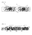
- Each of the arrows identified with A to C shows the thickness of the thermosetting resin base material, thermoplastic resin, and conductive agent, respectively.
- the samples were heated to temperatures ranging from 20°C, elevated by 10 degrees. At each temperature, the sample was sandwiched with gold-plated electrodes, and then the DC amperage at constant voltage was measured to obtain the resistance at each of the electrode temperature. The lowest temperature at which the resistance starts to elevate was taken as the temperature at which the resistance starts to increase (resistance increase starting temperature). In addition, the value obtained by dividing the maximum resistance value with the resistance value at 20°C was taken as the resistance ratio.
- An insulating polyester tape (NP-T tape available from Nitto Denko Corporation) having a width of 10mm was adhered onto the surface of the sample, and was firmly adhered by pressing with hand. Subsequently, the tape was peeled off at once with a large force, and the peeled-off surface was observed.
- the sample was immersed in NMP solution for 60 seconds at ambient temperature. The sample was taken out from the NMP solution, and then the NMP remaining on the surface was wiped off quickly. Scratch test was carried out immediately after. A 2-pond hammer with 10-fold gauze was reciprocated, and the times of reciprocation until change was observed in the resin layer (decolorization, peel off, decrease in resin thickness) were counted. The maximum times of reciprocation were 20.
- Comparative Example 1 the conductive agent was dispersed into the thermosetting resin base material before the hardening of the thermosetting resin when the resin layer was baked, due to the extremely low melting point of the thermoplastic resin. Accordingly, the shut down function was not appropriately achieved.
- thermoplastic resin and the conductive agent were not fused, resulting in a condition where the thermoplastic resin and the conductive agent are just placed adjacently to be dispersed in the thermosetting resin base material, since the baking temperature was by far lower than the melting point of the thermoplastic resin. Therefore, the conductive agent would not apart even when the thermoplastic resin expanded, and thus the shut down function was not appropriately achieved.
- thermosetting resin base material was decomposed due to the extremely high baking temperature of the resin layer. Accordingly, the adhesion property of the resin layer and the solvent resistance decreased.
- thermosetting resin solution was prepared using an organic solvent, resulting in dispersion of the thermoplastic resin and the conductive agent into the thermosetting resin base material. Accordingly, electrical conductivity was maintained even at elevated temperature, and thus the shut down function was not appropriately achieved.
- Comparative Example 5 the entirety of the resin layer was thermoplastic resin-based, since the hardening agent was not contained in the thermosetting resin solution. Accordingly, the resin layer was easily imbibed by the solvent contained in the active material paste, resulting in decrease in the adhesion property and decrease in the solvent resistance.
- thermoplastic resin was embedded in the thermosetting resin, since the thickness of the thermoplastic resin to the thickness of the thermosetting resin was small. Accordingly, the active material and the thermoplastic resin hardly came in contact with each other, resulting in less conductive pathway. Therefore, the electrical resistance at ambient temperature was high.
- the conductive agent was thin, since the formulation amount of the thermoplastic resin to the conductive agent was large. Accordingly, the electrical resistance at ambient temperature was high. In addition, the thermoplastic resin was thick, since the formulation amount of the thermoplastic resin to the thermosetting resin was excessively large. Accordingly, the thermoplastic resin was prone to detachment, resulting in inferior solvent resistance.
- Comparative Example 11 the conductive pathway was less, since the formulation amount of the thermoplastic resin was small. Accordingly, the electrical resistance at ambient temperature was high.
Landscapes
- Chemical & Material Sciences (AREA)
- Engineering & Computer Science (AREA)
- Electrochemistry (AREA)
- General Chemical & Material Sciences (AREA)
- Chemical Kinetics & Catalysis (AREA)
- Materials Engineering (AREA)
- Composite Materials (AREA)
- Power Engineering (AREA)
- Microelectronics & Electronic Packaging (AREA)
- Manufacturing & Machinery (AREA)
- Cell Electrode Carriers And Collectors (AREA)
- Battery Electrode And Active Subsutance (AREA)
- Electric Double-Layer Capacitors Or The Like (AREA)
Applications Claiming Priority (2)
| Application Number | Priority Date | Filing Date | Title |
|---|---|---|---|
| JP2012111112 | 2012-05-15 | ||
| PCT/JP2013/063129 WO2013172256A1 (ja) | 2012-05-15 | 2013-05-10 | 集電体、電極構造体、非水電解質電池及び蓄電部品、集電体の製造方法 |
Publications (2)
| Publication Number | Publication Date |
|---|---|
| EP2851982A1 true EP2851982A1 (de) | 2015-03-25 |
| EP2851982A4 EP2851982A4 (de) | 2016-01-13 |
Family
ID=49583662
Family Applications (1)
| Application Number | Title | Priority Date | Filing Date |
|---|---|---|---|
| EP13791238.2A Withdrawn EP2851982A4 (de) | 2012-05-15 | 2013-05-10 | Kollektor, elektrodenstruktur, batterie mit nichtwässrigem elektrolyt und speicherbauelementen sowie verfahren zur herstellung des kollektors |
Country Status (7)
| Country | Link |
|---|---|
| US (1) | US9508994B2 (de) |
| EP (1) | EP2851982A4 (de) |
| JP (1) | JPWO2013172256A1 (de) |
| KR (1) | KR20150015503A (de) |
| CN (1) | CN104254940B (de) |
| TW (1) | TW201351766A (de) |
| WO (1) | WO2013172256A1 (de) |
Families Citing this family (12)
| Publication number | Priority date | Publication date | Assignee | Title |
|---|---|---|---|---|
| JP2018006589A (ja) | 2016-07-04 | 2018-01-11 | 太陽誘電株式会社 | 電気化学デバイス用電極、電気化学デバイス及び電気化学デバイス用電極の製造方法 |
| US9893361B1 (en) * | 2016-09-19 | 2018-02-13 | Marc Jaker | Electrochemical cells and methods for making same |
| KR102443061B1 (ko) * | 2017-03-15 | 2022-09-14 | 삼성전자주식회사 | 온도 변화에 따른 가변층을 포함하는 재충전가능한 배터리 |
| CN109390584A (zh) | 2017-08-11 | 2019-02-26 | 财团法人工业技术研究院 | 负电极与锂电池 |
| JP6816696B2 (ja) * | 2017-10-13 | 2021-01-20 | トヨタ自動車株式会社 | 負極、およびそれを備える非水電解質二次電池 |
| CN111200110A (zh) * | 2018-11-16 | 2020-05-26 | 宁德时代新能源科技股份有限公司 | 一种正极极片及电化学装置 |
| CN111200113B (zh) * | 2018-11-16 | 2021-01-12 | 宁德时代新能源科技股份有限公司 | 一种正极极片及电化学装置 |
| CN114730885B (zh) * | 2019-12-02 | 2024-03-22 | 合肥国轩高科动力能源有限公司 | 用于锂离子电池的高取向集电极及其制造方法与应用 |
| JP7527373B2 (ja) * | 2019-12-02 | 2024-08-02 | ホーフェイ ゴション ハイテク パワー エナジー カンパニー リミテッド | リチウムイオン電池用の異方性コレクタならびにその製造方法および使用 |
| CN111454533B (zh) | 2020-04-09 | 2023-01-31 | 立讯精密工业股份有限公司 | 一种导电塑胶及其应用 |
| CN115425234A (zh) * | 2022-08-29 | 2022-12-02 | 浙江柔震科技有限公司 | 复合集流体及其制备方法 |
| KR20250042575A (ko) * | 2023-09-20 | 2025-03-27 | 삼성에스디아이 주식회사 | 리튬금속전지, 및 리튬금속전지 제조방법 |
Family Cites Families (10)
| Publication number | Priority date | Publication date | Assignee | Title |
|---|---|---|---|---|
| JP3409190B2 (ja) | 1993-06-17 | 2003-05-26 | ソニーケミカル株式会社 | ヒューズ抵抗器 |
| JP3012479B2 (ja) * | 1995-02-15 | 2000-02-21 | 東洋鋼鈑株式会社 | 電池ケース用被覆金属板、電池ケース及び電池 |
| JPH10270084A (ja) | 1997-03-27 | 1998-10-09 | Seiko Instr Inc | 非水電解質二次電池 |
| JP2001357854A (ja) * | 2000-06-13 | 2001-12-26 | Matsushita Electric Ind Co Ltd | 非水系二次電池 |
| TWI251359B (en) | 2003-10-10 | 2006-03-11 | Lg Cable Ltd | Lithium secondary battery having PTC powder and manufacturing method thereof |
| CN102349181B (zh) * | 2009-03-12 | 2016-02-10 | 日产自动车株式会社 | 双极型电池用集电体和双极型电池 |
| US8415004B2 (en) * | 2009-11-12 | 2013-04-09 | Taiflex Scientific Co., Ltd. | Low thermal-impedance insulated metal substrate and method for manufacturing the same |
| RU2544484C2 (ru) * | 2009-11-20 | 2015-03-20 | Ниссан Мотор Ко., Лтд. | Токосъемник для двухполюсной аккумуляторной батареи |
| US20140065491A1 (en) * | 2011-04-26 | 2014-03-06 | Showa Denko K.K. | Secondary battery |
| JP6125265B2 (ja) * | 2012-05-07 | 2017-05-10 | 日東電工株式会社 | 積層型導電シート、その製造方法、集電体およびバイポーラ電池 |
-
2013
- 2013-05-10 CN CN201380021616.0A patent/CN104254940B/zh not_active Expired - Fee Related
- 2013-05-10 JP JP2014515592A patent/JPWO2013172256A1/ja active Pending
- 2013-05-10 KR KR1020147035116A patent/KR20150015503A/ko not_active Withdrawn
- 2013-05-10 TW TW102116737A patent/TW201351766A/zh unknown
- 2013-05-10 EP EP13791238.2A patent/EP2851982A4/de not_active Withdrawn
- 2013-05-10 WO PCT/JP2013/063129 patent/WO2013172256A1/ja not_active Ceased
- 2013-05-10 US US14/397,115 patent/US9508994B2/en not_active Expired - Fee Related
Also Published As
| Publication number | Publication date |
|---|---|
| US20150125757A1 (en) | 2015-05-07 |
| US9508994B2 (en) | 2016-11-29 |
| KR20150015503A (ko) | 2015-02-10 |
| CN104254940B (zh) | 2017-03-15 |
| JPWO2013172256A1 (ja) | 2016-01-12 |
| CN104254940A (zh) | 2014-12-31 |
| HK1204711A1 (en) | 2015-11-27 |
| TW201351766A (zh) | 2013-12-16 |
| EP2851982A4 (de) | 2016-01-13 |
| WO2013172256A1 (ja) | 2013-11-21 |
Similar Documents
| Publication | Publication Date | Title |
|---|---|---|
| US9508994B2 (en) | Current collector, electrode structure, nonaqueous electrolyte battery and electrical storage device, and method for producing current collector | |
| EP2922124B1 (de) | Kollektor, elektrodenstruktur, elektrizitätsspeicherungskomponente und zusammensetzung für kollektoren | |
| EP2922122A1 (de) | Kollektor, elektrodenstrukturkörper und elektrisches speicherbauelement | |
| US9786919B2 (en) | Current collector, electrode structure, nonaqueous electrolyte battery and electrical storage device, and method for producing current collector | |
| EP2899783A1 (de) | Stromkollektor, elektrodenstruktur und stromspeicherkomponente | |
| EP2835851A1 (de) | Kollektor, elektrodenstruktur, batterie mit nichtwässrigem elektrolyt und stromspeicherkomponente | |
| KR20070100353A (ko) | 이차전지용 집전기, 이차전지 양극, 이차전지 음극,이차전지 및 그들의 제조 방법 | |
| KR20150001816A (ko) | 집전체, 전극 구조체, 비수전해질 전지 및 축전 부품 | |
| US9336959B2 (en) | Collector, electrode structure, non-aqueous electrolyte cell, and electrical storage device | |
| JP5888079B2 (ja) | セパレータ、及びそれを用いた非水系二次電池 | |
| US9911546B2 (en) | Current collector, electrode structure, nonaqueous electrolyte battery, electrical storage device, and nitrocellulose resin material | |
| HK1204711B (en) | Collector, electrode structure, nonaqueous electrolyte battery and power storage component, and method for producing collector | |
| JP2015144049A (ja) | 正極ペースト及びその製造方法 |
Legal Events
| Date | Code | Title | Description |
|---|---|---|---|
| PUAI | Public reference made under article 153(3) epc to a published international application that has entered the european phase |
Free format text: ORIGINAL CODE: 0009012 |
|
| 17P | Request for examination filed |
Effective date: 20141205 |
|
| AK | Designated contracting states |
Kind code of ref document: A1 Designated state(s): AL AT BE BG CH CY CZ DE DK EE ES FI FR GB GR HR HU IE IS IT LI LT LU LV MC MK MT NL NO PL PT RO RS SE SI SK SM TR |
|
| AX | Request for extension of the european patent |
Extension state: BA ME |
|
| RAP1 | Party data changed (applicant data changed or rights of an application transferred) |
Owner name: UACJ CORPORATION Owner name: UACJ FOIL CORPORATION |
|
| DAX | Request for extension of the european patent (deleted) | ||
| RA4 | Supplementary search report drawn up and despatched (corrected) |
Effective date: 20151210 |
|
| RIC1 | Information provided on ipc code assigned before grant |
Ipc: H01M 2/34 20060101ALI20151204BHEP Ipc: H01G 11/28 20130101ALI20151204BHEP Ipc: H01M 4/82 20060101ALI20151204BHEP Ipc: H01M 4/13 20100101ALI20151204BHEP Ipc: H01G 11/70 20130101ALI20151204BHEP Ipc: H01M 10/052 20100101ALN20151204BHEP Ipc: H01M 4/66 20060101AFI20151204BHEP |
|
| STAA | Information on the status of an ep patent application or granted ep patent |
Free format text: STATUS: THE APPLICATION IS DEEMED TO BE WITHDRAWN |
|
| 18D | Application deemed to be withdrawn |
Effective date: 20160719 |