EP2835552B1 - Vorrichtung zur steuerung von startkupplungen für fahrzeuge - Google Patents
Vorrichtung zur steuerung von startkupplungen für fahrzeuge Download PDFInfo
- Publication number
- EP2835552B1 EP2835552B1 EP12873833.3A EP12873833A EP2835552B1 EP 2835552 B1 EP2835552 B1 EP 2835552B1 EP 12873833 A EP12873833 A EP 12873833A EP 2835552 B1 EP2835552 B1 EP 2835552B1
- Authority
- EP
- European Patent Office
- Prior art keywords
- torque
- engine
- clutch
- turbine
- speed
- Prior art date
- Legal status (The legal status is an assumption and is not a legal conclusion. Google has not performed a legal analysis and makes no representation as to the accuracy of the status listed.)
- Active
Links
Images


Classifications
-
- F—MECHANICAL ENGINEERING; LIGHTING; HEATING; WEAPONS; BLASTING
- F16—ENGINEERING ELEMENTS AND UNITS; GENERAL MEASURES FOR PRODUCING AND MAINTAINING EFFECTIVE FUNCTIONING OF MACHINES OR INSTALLATIONS; THERMAL INSULATION IN GENERAL
- F16D—COUPLINGS FOR TRANSMITTING ROTATION; CLUTCHES; BRAKES
- F16D48/00—External control of clutches
- F16D48/06—Control by electric or electronic means, e.g. of fluid pressure
- F16D48/066—Control of fluid pressure, e.g. using an accumulator
-
- B—PERFORMING OPERATIONS; TRANSPORTING
- B60—VEHICLES IN GENERAL
- B60W—CONJOINT CONTROL OF VEHICLE SUB-UNITS OF DIFFERENT TYPE OR DIFFERENT FUNCTION; CONTROL SYSTEMS SPECIALLY ADAPTED FOR HYBRID VEHICLES; ROAD VEHICLE DRIVE CONTROL SYSTEMS FOR PURPOSES NOT RELATED TO THE CONTROL OF A PARTICULAR SUB-UNIT
- B60W10/00—Conjoint control of vehicle sub-units of different type or different function
- B60W10/02—Conjoint control of vehicle sub-units of different type or different function including control of driveline clutches
- B60W10/023—Fluid clutches
-
- B—PERFORMING OPERATIONS; TRANSPORTING
- B60—VEHICLES IN GENERAL
- B60W—CONJOINT CONTROL OF VEHICLE SUB-UNITS OF DIFFERENT TYPE OR DIFFERENT FUNCTION; CONTROL SYSTEMS SPECIALLY ADAPTED FOR HYBRID VEHICLES; ROAD VEHICLE DRIVE CONTROL SYSTEMS FOR PURPOSES NOT RELATED TO THE CONTROL OF A PARTICULAR SUB-UNIT
- B60W10/00—Conjoint control of vehicle sub-units of different type or different function
- B60W10/04—Conjoint control of vehicle sub-units of different type or different function including control of propulsion units
- B60W10/06—Conjoint control of vehicle sub-units of different type or different function including control of propulsion units including control of combustion engines
-
- F—MECHANICAL ENGINEERING; LIGHTING; HEATING; WEAPONS; BLASTING
- F16—ENGINEERING ELEMENTS AND UNITS; GENERAL MEASURES FOR PRODUCING AND MAINTAINING EFFECTIVE FUNCTIONING OF MACHINES OR INSTALLATIONS; THERMAL INSULATION IN GENERAL
- F16D—COUPLINGS FOR TRANSMITTING ROTATION; CLUTCHES; BRAKES
- F16D48/00—External control of clutches
- F16D48/06—Control by electric or electronic means, e.g. of fluid pressure
- F16D48/08—Regulating clutch take-up on starting
-
- B—PERFORMING OPERATIONS; TRANSPORTING
- B60—VEHICLES IN GENERAL
- B60W—CONJOINT CONTROL OF VEHICLE SUB-UNITS OF DIFFERENT TYPE OR DIFFERENT FUNCTION; CONTROL SYSTEMS SPECIALLY ADAPTED FOR HYBRID VEHICLES; ROAD VEHICLE DRIVE CONTROL SYSTEMS FOR PURPOSES NOT RELATED TO THE CONTROL OF A PARTICULAR SUB-UNIT
- B60W30/00—Purposes of road vehicle drive control systems not related to the control of a particular sub-unit, e.g. of systems using conjoint control of vehicle sub-units
- B60W30/18—Propelling the vehicle
- B60W30/18009—Propelling the vehicle related to particular drive situations
- B60W30/18072—Coasting
- B60W2030/1809—Without torque flow between driveshaft and engine, e.g. with clutch disengaged or transmission in neutral
-
- B—PERFORMING OPERATIONS; TRANSPORTING
- B60—VEHICLES IN GENERAL
- B60W—CONJOINT CONTROL OF VEHICLE SUB-UNITS OF DIFFERENT TYPE OR DIFFERENT FUNCTION; CONTROL SYSTEMS SPECIALLY ADAPTED FOR HYBRID VEHICLES; ROAD VEHICLE DRIVE CONTROL SYSTEMS FOR PURPOSES NOT RELATED TO THE CONTROL OF A PARTICULAR SUB-UNIT
- B60W2510/00—Input parameters relating to a particular sub-units
- B60W2510/06—Combustion engines, Gas turbines
- B60W2510/0604—Throttle position
-
- B—PERFORMING OPERATIONS; TRANSPORTING
- B60—VEHICLES IN GENERAL
- B60W—CONJOINT CONTROL OF VEHICLE SUB-UNITS OF DIFFERENT TYPE OR DIFFERENT FUNCTION; CONTROL SYSTEMS SPECIALLY ADAPTED FOR HYBRID VEHICLES; ROAD VEHICLE DRIVE CONTROL SYSTEMS FOR PURPOSES NOT RELATED TO THE CONTROL OF A PARTICULAR SUB-UNIT
- B60W2510/00—Input parameters relating to a particular sub-units
- B60W2510/06—Combustion engines, Gas turbines
- B60W2510/0614—Position of fuel or air injector
- B60W2510/0628—Inlet air flow rate
-
- B—PERFORMING OPERATIONS; TRANSPORTING
- B60—VEHICLES IN GENERAL
- B60W—CONJOINT CONTROL OF VEHICLE SUB-UNITS OF DIFFERENT TYPE OR DIFFERENT FUNCTION; CONTROL SYSTEMS SPECIALLY ADAPTED FOR HYBRID VEHICLES; ROAD VEHICLE DRIVE CONTROL SYSTEMS FOR PURPOSES NOT RELATED TO THE CONTROL OF A PARTICULAR SUB-UNIT
- B60W2510/00—Input parameters relating to a particular sub-units
- B60W2510/06—Combustion engines, Gas turbines
- B60W2510/0638—Engine speed
-
- B—PERFORMING OPERATIONS; TRANSPORTING
- B60—VEHICLES IN GENERAL
- B60W—CONJOINT CONTROL OF VEHICLE SUB-UNITS OF DIFFERENT TYPE OR DIFFERENT FUNCTION; CONTROL SYSTEMS SPECIALLY ADAPTED FOR HYBRID VEHICLES; ROAD VEHICLE DRIVE CONTROL SYSTEMS FOR PURPOSES NOT RELATED TO THE CONTROL OF A PARTICULAR SUB-UNIT
- B60W2710/00—Output or target parameters relating to a particular sub-units
- B60W2710/02—Clutches
- B60W2710/021—Clutch engagement state
- B60W2710/023—Clutch engagement rate
-
- B—PERFORMING OPERATIONS; TRANSPORTING
- B60—VEHICLES IN GENERAL
- B60W—CONJOINT CONTROL OF VEHICLE SUB-UNITS OF DIFFERENT TYPE OR DIFFERENT FUNCTION; CONTROL SYSTEMS SPECIALLY ADAPTED FOR HYBRID VEHICLES; ROAD VEHICLE DRIVE CONTROL SYSTEMS FOR PURPOSES NOT RELATED TO THE CONTROL OF A PARTICULAR SUB-UNIT
- B60W2710/00—Output or target parameters relating to a particular sub-units
- B60W2710/06—Combustion engines, Gas turbines
- B60W2710/0605—Throttle position
-
- B—PERFORMING OPERATIONS; TRANSPORTING
- B60—VEHICLES IN GENERAL
- B60W—CONJOINT CONTROL OF VEHICLE SUB-UNITS OF DIFFERENT TYPE OR DIFFERENT FUNCTION; CONTROL SYSTEMS SPECIALLY ADAPTED FOR HYBRID VEHICLES; ROAD VEHICLE DRIVE CONTROL SYSTEMS FOR PURPOSES NOT RELATED TO THE CONTROL OF A PARTICULAR SUB-UNIT
- B60W30/00—Purposes of road vehicle drive control systems not related to the control of a particular sub-unit, e.g. of systems using conjoint control of vehicle sub-units
- B60W30/18—Propelling the vehicle
- B60W30/18009—Propelling the vehicle related to particular drive situations
- B60W30/18018—Start-stop drive, e.g. in a traffic jam
-
- F—MECHANICAL ENGINEERING; LIGHTING; HEATING; WEAPONS; BLASTING
- F16—ENGINEERING ELEMENTS AND UNITS; GENERAL MEASURES FOR PRODUCING AND MAINTAINING EFFECTIVE FUNCTIONING OF MACHINES OR INSTALLATIONS; THERMAL INSULATION IN GENERAL
- F16D—COUPLINGS FOR TRANSMITTING ROTATION; CLUTCHES; BRAKES
- F16D2500/00—External control of clutches by electric or electronic means
- F16D2500/10—System to be controlled
- F16D2500/102—Actuator
- F16D2500/1026—Hydraulic
-
- F—MECHANICAL ENGINEERING; LIGHTING; HEATING; WEAPONS; BLASTING
- F16—ENGINEERING ELEMENTS AND UNITS; GENERAL MEASURES FOR PRODUCING AND MAINTAINING EFFECTIVE FUNCTIONING OF MACHINES OR INSTALLATIONS; THERMAL INSULATION IN GENERAL
- F16D—COUPLINGS FOR TRANSMITTING ROTATION; CLUTCHES; BRAKES
- F16D2500/00—External control of clutches by electric or electronic means
- F16D2500/10—System to be controlled
- F16D2500/104—Clutch
- F16D2500/10406—Clutch position
- F16D2500/10412—Transmission line of a vehicle
-
- F—MECHANICAL ENGINEERING; LIGHTING; HEATING; WEAPONS; BLASTING
- F16—ENGINEERING ELEMENTS AND UNITS; GENERAL MEASURES FOR PRODUCING AND MAINTAINING EFFECTIVE FUNCTIONING OF MACHINES OR INSTALLATIONS; THERMAL INSULATION IN GENERAL
- F16D—COUPLINGS FOR TRANSMITTING ROTATION; CLUTCHES; BRAKES
- F16D2500/00—External control of clutches by electric or electronic means
- F16D2500/10—System to be controlled
- F16D2500/104—Clutch
- F16D2500/10443—Clutch type
- F16D2500/1045—Friction clutch
-
- F—MECHANICAL ENGINEERING; LIGHTING; HEATING; WEAPONS; BLASTING
- F16—ENGINEERING ELEMENTS AND UNITS; GENERAL MEASURES FOR PRODUCING AND MAINTAINING EFFECTIVE FUNCTIONING OF MACHINES OR INSTALLATIONS; THERMAL INSULATION IN GENERAL
- F16D—COUPLINGS FOR TRANSMITTING ROTATION; CLUTCHES; BRAKES
- F16D2500/00—External control of clutches by electric or electronic means
- F16D2500/10—System to be controlled
- F16D2500/104—Clutch
- F16D2500/10443—Clutch type
- F16D2500/10487—Fluid coupling
-
- F—MECHANICAL ENGINEERING; LIGHTING; HEATING; WEAPONS; BLASTING
- F16—ENGINEERING ELEMENTS AND UNITS; GENERAL MEASURES FOR PRODUCING AND MAINTAINING EFFECTIVE FUNCTIONING OF MACHINES OR INSTALLATIONS; THERMAL INSULATION IN GENERAL
- F16D—COUPLINGS FOR TRANSMITTING ROTATION; CLUTCHES; BRAKES
- F16D2500/00—External control of clutches by electric or electronic means
- F16D2500/10—System to be controlled
- F16D2500/106—Engine
- F16D2500/1064—Electric
-
- F—MECHANICAL ENGINEERING; LIGHTING; HEATING; WEAPONS; BLASTING
- F16—ENGINEERING ELEMENTS AND UNITS; GENERAL MEASURES FOR PRODUCING AND MAINTAINING EFFECTIVE FUNCTIONING OF MACHINES OR INSTALLATIONS; THERMAL INSULATION IN GENERAL
- F16D—COUPLINGS FOR TRANSMITTING ROTATION; CLUTCHES; BRAKES
- F16D2500/00—External control of clutches by electric or electronic means
- F16D2500/10—System to be controlled
- F16D2500/106—Engine
- F16D2500/1068—Engine supercharger or turbocharger
-
- F—MECHANICAL ENGINEERING; LIGHTING; HEATING; WEAPONS; BLASTING
- F16—ENGINEERING ELEMENTS AND UNITS; GENERAL MEASURES FOR PRODUCING AND MAINTAINING EFFECTIVE FUNCTIONING OF MACHINES OR INSTALLATIONS; THERMAL INSULATION IN GENERAL
- F16D—COUPLINGS FOR TRANSMITTING ROTATION; CLUTCHES; BRAKES
- F16D2500/00—External control of clutches by electric or electronic means
- F16D2500/10—System to be controlled
- F16D2500/108—Gear
- F16D2500/1081—Actuation type
- F16D2500/1085—Automatic transmission
-
- F—MECHANICAL ENGINEERING; LIGHTING; HEATING; WEAPONS; BLASTING
- F16—ENGINEERING ELEMENTS AND UNITS; GENERAL MEASURES FOR PRODUCING AND MAINTAINING EFFECTIVE FUNCTIONING OF MACHINES OR INSTALLATIONS; THERMAL INSULATION IN GENERAL
- F16D—COUPLINGS FOR TRANSMITTING ROTATION; CLUTCHES; BRAKES
- F16D2500/00—External control of clutches by electric or electronic means
- F16D2500/10—System to be controlled
- F16D2500/108—Gear
- F16D2500/1088—CVT
-
- F—MECHANICAL ENGINEERING; LIGHTING; HEATING; WEAPONS; BLASTING
- F16—ENGINEERING ELEMENTS AND UNITS; GENERAL MEASURES FOR PRODUCING AND MAINTAINING EFFECTIVE FUNCTIONING OF MACHINES OR INSTALLATIONS; THERMAL INSULATION IN GENERAL
- F16D—COUPLINGS FOR TRANSMITTING ROTATION; CLUTCHES; BRAKES
- F16D2500/00—External control of clutches by electric or electronic means
- F16D2500/10—System to be controlled
- F16D2500/11—Application
- F16D2500/1107—Vehicles
-
- F—MECHANICAL ENGINEERING; LIGHTING; HEATING; WEAPONS; BLASTING
- F16—ENGINEERING ELEMENTS AND UNITS; GENERAL MEASURES FOR PRODUCING AND MAINTAINING EFFECTIVE FUNCTIONING OF MACHINES OR INSTALLATIONS; THERMAL INSULATION IN GENERAL
- F16D—COUPLINGS FOR TRANSMITTING ROTATION; CLUTCHES; BRAKES
- F16D2500/00—External control of clutches by electric or electronic means
- F16D2500/30—Signal inputs
- F16D2500/304—Signal inputs from the clutch
- F16D2500/3042—Signal inputs from the clutch from the output shaft
- F16D2500/30421—Torque of the output shaft
-
- F—MECHANICAL ENGINEERING; LIGHTING; HEATING; WEAPONS; BLASTING
- F16—ENGINEERING ELEMENTS AND UNITS; GENERAL MEASURES FOR PRODUCING AND MAINTAINING EFFECTIVE FUNCTIONING OF MACHINES OR INSTALLATIONS; THERMAL INSULATION IN GENERAL
- F16D—COUPLINGS FOR TRANSMITTING ROTATION; CLUTCHES; BRAKES
- F16D2500/00—External control of clutches by electric or electronic means
- F16D2500/30—Signal inputs
- F16D2500/306—Signal inputs from the engine
- F16D2500/3061—Engine inlet air flow rate
-
- F—MECHANICAL ENGINEERING; LIGHTING; HEATING; WEAPONS; BLASTING
- F16—ENGINEERING ELEMENTS AND UNITS; GENERAL MEASURES FOR PRODUCING AND MAINTAINING EFFECTIVE FUNCTIONING OF MACHINES OR INSTALLATIONS; THERMAL INSULATION IN GENERAL
- F16D—COUPLINGS FOR TRANSMITTING ROTATION; CLUTCHES; BRAKES
- F16D2500/00—External control of clutches by electric or electronic means
- F16D2500/30—Signal inputs
- F16D2500/306—Signal inputs from the engine
- F16D2500/3067—Speed of the engine
-
- F—MECHANICAL ENGINEERING; LIGHTING; HEATING; WEAPONS; BLASTING
- F16—ENGINEERING ELEMENTS AND UNITS; GENERAL MEASURES FOR PRODUCING AND MAINTAINING EFFECTIVE FUNCTIONING OF MACHINES OR INSTALLATIONS; THERMAL INSULATION IN GENERAL
- F16D—COUPLINGS FOR TRANSMITTING ROTATION; CLUTCHES; BRAKES
- F16D2500/00—External control of clutches by electric or electronic means
- F16D2500/30—Signal inputs
- F16D2500/306—Signal inputs from the engine
- F16D2500/3069—Engine ignition switch
-
- F—MECHANICAL ENGINEERING; LIGHTING; HEATING; WEAPONS; BLASTING
- F16—ENGINEERING ELEMENTS AND UNITS; GENERAL MEASURES FOR PRODUCING AND MAINTAINING EFFECTIVE FUNCTIONING OF MACHINES OR INSTALLATIONS; THERMAL INSULATION IN GENERAL
- F16D—COUPLINGS FOR TRANSMITTING ROTATION; CLUTCHES; BRAKES
- F16D2500/00—External control of clutches by electric or electronic means
- F16D2500/50—Problem to be solved by the control system
- F16D2500/502—Relating the clutch
- F16D2500/50224—Drive-off
-
- F—MECHANICAL ENGINEERING; LIGHTING; HEATING; WEAPONS; BLASTING
- F16—ENGINEERING ELEMENTS AND UNITS; GENERAL MEASURES FOR PRODUCING AND MAINTAINING EFFECTIVE FUNCTIONING OF MACHINES OR INSTALLATIONS; THERMAL INSULATION IN GENERAL
- F16D—COUPLINGS FOR TRANSMITTING ROTATION; CLUTCHES; BRAKES
- F16D2500/00—External control of clutches by electric or electronic means
- F16D2500/50—Problem to be solved by the control system
- F16D2500/502—Relating the clutch
- F16D2500/50287—Torque control
-
- F—MECHANICAL ENGINEERING; LIGHTING; HEATING; WEAPONS; BLASTING
- F16—ENGINEERING ELEMENTS AND UNITS; GENERAL MEASURES FOR PRODUCING AND MAINTAINING EFFECTIVE FUNCTIONING OF MACHINES OR INSTALLATIONS; THERMAL INSULATION IN GENERAL
- F16D—COUPLINGS FOR TRANSMITTING ROTATION; CLUTCHES; BRAKES
- F16D2500/00—External control of clutches by electric or electronic means
- F16D2500/50—Problem to be solved by the control system
- F16D2500/504—Relating the engine
- F16D2500/5043—Engine fuel consumption
-
- F—MECHANICAL ENGINEERING; LIGHTING; HEATING; WEAPONS; BLASTING
- F16—ENGINEERING ELEMENTS AND UNITS; GENERAL MEASURES FOR PRODUCING AND MAINTAINING EFFECTIVE FUNCTIONING OF MACHINES OR INSTALLATIONS; THERMAL INSULATION IN GENERAL
- F16D—COUPLINGS FOR TRANSMITTING ROTATION; CLUTCHES; BRAKES
- F16D2500/00—External control of clutches by electric or electronic means
- F16D2500/50—Problem to be solved by the control system
- F16D2500/508—Relating driving conditions
- F16D2500/50833—Control during a stability control operation [ESP]
-
- F—MECHANICAL ENGINEERING; LIGHTING; HEATING; WEAPONS; BLASTING
- F16—ENGINEERING ELEMENTS AND UNITS; GENERAL MEASURES FOR PRODUCING AND MAINTAINING EFFECTIVE FUNCTIONING OF MACHINES OR INSTALLATIONS; THERMAL INSULATION IN GENERAL
- F16D—COUPLINGS FOR TRANSMITTING ROTATION; CLUTCHES; BRAKES
- F16D2500/00—External control of clutches by electric or electronic means
- F16D2500/50—Problem to be solved by the control system
- F16D2500/508—Relating driving conditions
- F16D2500/50883—Stop-and-go, i.e. repeated stopping and starting, e.g. in traffic jams
-
- F—MECHANICAL ENGINEERING; LIGHTING; HEATING; WEAPONS; BLASTING
- F16—ENGINEERING ELEMENTS AND UNITS; GENERAL MEASURES FOR PRODUCING AND MAINTAINING EFFECTIVE FUNCTIONING OF MACHINES OR INSTALLATIONS; THERMAL INSULATION IN GENERAL
- F16D—COUPLINGS FOR TRANSMITTING ROTATION; CLUTCHES; BRAKES
- F16D2500/00—External control of clutches by electric or electronic means
- F16D2500/70—Details about the implementation of the control system
- F16D2500/704—Output parameters from the control unit; Target parameters to be controlled
- F16D2500/70402—Actuator parameters
- F16D2500/70408—Torque
-
- F—MECHANICAL ENGINEERING; LIGHTING; HEATING; WEAPONS; BLASTING
- F16—ENGINEERING ELEMENTS AND UNITS; GENERAL MEASURES FOR PRODUCING AND MAINTAINING EFFECTIVE FUNCTIONING OF MACHINES OR INSTALLATIONS; THERMAL INSULATION IN GENERAL
- F16D—COUPLINGS FOR TRANSMITTING ROTATION; CLUTCHES; BRAKES
- F16D2500/00—External control of clutches by electric or electronic means
- F16D2500/70—Details about the implementation of the control system
- F16D2500/704—Output parameters from the control unit; Target parameters to be controlled
- F16D2500/70402—Actuator parameters
- F16D2500/7041—Position
-
- F—MECHANICAL ENGINEERING; LIGHTING; HEATING; WEAPONS; BLASTING
- F16—ENGINEERING ELEMENTS AND UNITS; GENERAL MEASURES FOR PRODUCING AND MAINTAINING EFFECTIVE FUNCTIONING OF MACHINES OR INSTALLATIONS; THERMAL INSULATION IN GENERAL
- F16D—COUPLINGS FOR TRANSMITTING ROTATION; CLUTCHES; BRAKES
- F16D2500/00—External control of clutches by electric or electronic means
- F16D2500/70—Details about the implementation of the control system
- F16D2500/704—Output parameters from the control unit; Target parameters to be controlled
- F16D2500/70422—Clutch parameters
- F16D2500/70438—From the output shaft
- F16D2500/7044—Output shaft torque
-
- F—MECHANICAL ENGINEERING; LIGHTING; HEATING; WEAPONS; BLASTING
- F16—ENGINEERING ELEMENTS AND UNITS; GENERAL MEASURES FOR PRODUCING AND MAINTAINING EFFECTIVE FUNCTIONING OF MACHINES OR INSTALLATIONS; THERMAL INSULATION IN GENERAL
- F16D—COUPLINGS FOR TRANSMITTING ROTATION; CLUTCHES; BRAKES
- F16D2500/00—External control of clutches by electric or electronic means
- F16D2500/70—Details about the implementation of the control system
- F16D2500/704—Output parameters from the control unit; Target parameters to be controlled
- F16D2500/70452—Engine parameters
- F16D2500/70462—Opening of the throttle valve
Definitions
- the present invention relates to a system for controlling a starting clutch for connecting a prime mover such as an engine with a transmission mechanism, and more particularly, to a system for controlling a torque transmitting capacity of the starting clutch responsive to a torque inputted through a torque converter.
- a required drive force is changed while a vehicle is running, and an energy efficiency of a prime mover is deteriorated if the prime mover is operated at an operating point (or a driving point) away from a predetermined optimum operating point. Therefore, a transmission is arranged on an output side of the prime mover, and a drive force is adjusted in accordance with a speed ratio while controlling a rotational speed of the prime mover in an optimally energy efficient manner.
- an automatic geared transmission adapted to change a speed ratio stepwise and a continuously variable transmission adapted to change a speed ratio continuously are used in vehicles.
- a torque converter is disposed between the engine and the transmission to keep the engine driving in a stopping vehicle.
- the torque converter is adapted to transmit a torque by rotating a turbine by a spiral oil flow created by a pump impeller.
- the torque is amplified by altering a direction of the oil flow returning to the pump impeller by a reaction force of a stator under the condition that a speed difference between the pump impeller and the turbine is large (i.e., if a speed ratio is small). Accordingly, a creep torque is generated under the condition that the speed ratio is small. Nonetheless, the torque applied to the transmission connected to an output side of the torque converter is changed responsive to the speed ratio of the torque converter.
- an oil pressure applied to engagement elements of the transmission such as a clutch and a brake is controlled to control a torque transmitting capacity thereof in accordance with a condition of the torque converter.
- JP H11 325232 A The control system taught by JP H11 325232 A is applied to a vehicle in which an automatic geared transmission is connected to an output side of an internal combustion engine to control hydraulic pressure applied to a clutch of the transmission.
- an engine torque starts to be changed after a lag behind an accelerating operation, and a delay in hydraulic response is also caused. Therefore, a hydraulic pressure applied to the clutch may be changed after a lag behind an increase in a turbine torque of the torque converter interposed between the engine and the transmission.
- an engine torque is calculated based on parameters representing an engine load such as an opening degree of an accelerator and an air-intake, and an engine speed
- an input torque of the clutch is calculated based on the calculated engine torque and the engine speed. That is, the engine torque is changed in accordance with the engine speed and a physical amount of the air-intake. Therefore, the engine torque is calculated first of all based on the parameters representing the engine load and the engine speed.
- a turbine torque of the torque converter can be calculated based on an input torque, a capacity coefficient, a speed ratio and so on.
- a clutch torque corresponding to the turbine torque is then calculated based on the engine torque corresponding to the input torque and the engine speed corresponding to the input speed.
- a torque transmitting capacity of the clutch is increased with an increase in the hydraulic pressure. Therefore, if the input torque is known, the hydraulic pressure can be calculated based on the input torque.
- JP 2005 291174 A describes a torque control device configured to estimate an engine torque.
- the estimation torque is calculated using a torque converter characteristic defined based on a relation between an input shaft speed and an output shaft speed. Specifically, the estimation torque is calculated by multiplying a coefficient of capacity of a torque converter by a speed ratio and a square of the input speed, and by adding inertia torques of an engine and the torque converter and a loss torque of an auxiliary to the product.
- an engine torque characteristic is learnt by comparing the estimation torque using the torque converter characteristic with the estimation torque based on an air quantity, and such learning of the engine torque characteristic is inhibited provided that a predetermined condition is satisfied. For example, the learning of the engine torque characteristic is inhibited if a change rate of an input speed or an output speed is large.
- JP H11 325232 A the parameters representing the engine load can be detected in short time so that the above-explained time lag can be ignored. Therefore, the hydraulic pressure applied to the clutch can be controlled without delay.
- the control taught by JP H11 325232 A is carried out utilizing a predetermined relation between the parameter such as a throttle opening or an air intake and an output torque. That is, the control delay of the clutch can be eliminated by the control system taught by JP H11 325232 A , however, the pressure would be applied to the clutch excessively or insufficiently if the engine torque or the input torque of the clutch cannot be detected accurately.
- stop and start control may be executed optionally to improve fuel economy upon satisfaction of a predetermined condition.
- the stop and start control specifically, the engine is stopped when the accelerator is closed completely, and the engine is restarted when such condition is eliminated.
- the torque converter is disconnected from the transmission by disengaging the clutch during stopping the engine, and the clutch is engaged when the engine is restarted.
- an air fuel-ratio is controlled to be richer than that under the situation in which the engine rotates autonomously. That is, the relation between the throttle opening or an air intake and the output torque is deviated from the predetermined relation.
- the torque control device taught by JP 2005 291174 A is configured to learn and inhibit the engine torque characteristic depending on a situation.
- the engine torque characteristic is estimated based on the characteristic of the torque converter, however, the estimated value will not be reflected as an actual torque on the control.
- the torque thus estimated using the torque converter characteristic is compared with the estimated torque based on an air quantity.
- the relation between the estimated torque and the engine load differs under the condition that the engine is operated unstably during restarting. In this case, therefore, the engine torque cannot be estimated accurately and the control taught by JP 2005 291174 A cannot be carried out.
- US 2011/196590 A1 shows a start control device and a start control method of a vehicular power transmission system including a lock-up clutch and a start clutch in which start-time lock-up slip control is performed, and neutral control is performed.
- the start-time lock-up slip control is additionally executed during cancellation of the neutral control, the gradient of an output rotational speed of the hydraulic power transmission which is changed, through engagement of the start clutch, toward an input rotational speed of the automatic transmission at the time of completion of engagement of the start clutch is controlled, using at least one of a start clutch pressure that is increased so as to engage the start clutch, and a lock-up clutch pressure that is increased so as to bring the lock-up clutch into slip engagement.
- the present invention has been conceived noting the foregoing technical problems, and it is an object of the present invention is to provide a starting clutch control system for a vehicle, which is configured to adjust hydraulic pressure governing a torque transmitting capacity of the clutch to an engine torque applied to the clutch in the event of starting an engine while engaging the clutch.
- the starting clutch control system is applied to a vehicle in which a torque generated by an engine is inputted to a torque converter comprised of a pump impeller and a turbine, and the torque is outputted from the torque converter to driving wheels through a starting clutch.
- the starting clutch control system is configured to stop the engine while disengaging the starting dutch upon satisfaction of a predetermined condition when the vehicle is running, and to restart the stopping engine while engaging the starting clutch upon satisfaction of a predetermined restarting condition.
- the starting clutch control system is configured: to estimate a torque of a turbine of the torque converter based on an engine speed, and a capacity coefficient and a torque ratio of the torque converter, when the engine is required to increase a power to be restarted; to increase a torque transmitting capacity of the clutch in accordance with the estimated torque of the turbine; to estimate the torque of the turbine based on an air intake of the engine and an engine speed after a completion of an engagement of the clutch; and to control the torque transmitting capacity of the clutch in accordance with the estimated torque of the turbine.
- the starting clutch control system is further configured to control the torque transmitting capacity of the clutch in accordance with the torque of the turbine estimated based on the air intake of the engine and the engine speed instead of the torque of the turbine estimated based on the engine speed, and the capacity coefficient and the torque ratio of the torque converter, if a demand to increase the engine power is eliminated during increasing the torque transmitting capacity of the clutch.
- the torque of the turbine to be used to control the torque transmitting capacity of the clutch is switched from the torque of the turbine estimated based on the engine speed, and the capacity coefficient and the torque ratio of the torque converter, to the torque of the turbine estimated based on the an air intake of the engine and the engine speed, if a difference between those estimated torques is smaller than a predetermined value.
- a friction clutch whose torque transmitting capacity is increased by increasing hydraulic pressure applied thereto is used as the clutch.
- the hydraulic pressure applied to the friction clutch is corrected in accordance with an opening degree of a throttle valve of the vehicle or a speed ratio of the clutch.
- the hydraulic pressure applied to the friction clutch is corrected to be lowered in case the opening degree of the throttle valve or the speed ratio is large, in comparison with a case in which the opening degree of the throttle valve or the speed ratio is small.
- the starting clutch control system is further configured to estimate the torque of the turbine of the torque converter based on the engine speed, and the capacity coefficient and the torque ratio of the torque converter, after a complete explosion of fuel is achieved in the restarted engine, and to increase the torque transmitting capacity of the clutch in accordance with the estimated torque of the turbine.
- the demand to increase the engine power is determined based on an augmentation of the opening degree of the accelerator or the throttle valve.
- the starting clutch control system estimates the turbine torque based on the an air intake of the engine that is changed immediately responsive to a change in the demand to increase the engine power, and controls the torque transmitting capacity of the clutch in accordance with the turbine torque thus estimated. Therefore, a drive force will not be generated unintentionally under the situation where the demand to increase the engine power is eliminated, so that a period of so-called "free running" can be shortened.
- shocks and uncomfortable feeling can be reduced more certainly by switching the estimated value of the turbine torque used to calculate the torque transmitting capacity of the clutch from the value estimated based on the engine speed etc. to the value estimated based on the an air intake of the engine, under the condition where those estimated torques are close to each other.
- a change in the drive force or the longitudinal acceleration can be mitigated to reduce the shocks as a cause of uncomfortable feeling, by correcting the hydraulic pressure applied to the clutch based on the opening degree of the throttle valve or the speed ratio of the clutch.
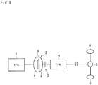
- a vehicle to which the present invention is applied.
- the vehicle is comprised of an engine 1 (E/G), a torque converter 2, a starting clutch 3, and a transmission 4 (T/M).
- a torque of the transmission 4 is delivered to a pair of driving wheels 6 via a final reduction gear unit 5.
- the engine 1 is an internal combustion engine adapted to generate power by burning fuel such as a gasoline engine, a diesel engine, a gas engine and so on.
- the gasoline engine is used as the engine 1, and an output torque of the engine 1 differs depending on an air intake.
- the engine 1 is provided with a not shown starter motor so that the engine 1 is allowed to be restarted even after stopped by stopping fuel supply.
- the torque converter 2 is comprised of a pump impeller 7 rotated by the engine 1, a turbine 8 rotated by receiving a spiral oil flow created by the pump impeller 7, and a stator 9 interposed between the pump impeller 7 and the turbine 8.
- the stator 9 is fixed to a predetermined fixing portion through a one-way clutch (not shown). Accordingly, the torque converter 2 has an ability to multiply torque within a converter range so that torque applied to the starting clutch 3 is changed in accordance with a speed ratio or a torque ratio of the torque converter 2.
- the starting clutch 3 is an engagement device adapted to selectively allow and interrupt torque transmission between the engine 1 and the transmission 4.
- a friction clutch whose torque transmitting capacity can be changed, more preferably, a multiple disc clutch whose torque transmitting capacity is controlled hydraulically is used as the starting clutch 3.
- the transmission 4 not only an automatic geared transmission adapted to change a speed ratio stepwise but also a continuously variable transmission adapted to change a speed ratio continuously may be employed.
- the starting clutch 3 may be incorporated into the transmission 4.
- the control system of the present invention is applied to the vehicle having a powertrain thus structured.
- stop and start control (abbreviated as “S & S control” hereinafter) is carried out to stop the engine 1 upon satisfaction of a predetermined execution condition, and to restart upon satisfaction of a predetermined restarting condition.
- the S & S control includes: "stop-based S & S control" for stopping the engine 1 based on a fact that vehicle is stopped; “deceleration-based S & S control” for stopping the engine 1 automatically based on a fact that the vehicle is decelerated to be stopped by depressing a brake pedal while returning an accelerator pedal; and “free run S & S control” for stopping the engine 1 automatically based on a fact that the accelerator pedal is returned at a vehicle speed higher than a predetermined speed.
- the stop-based S & S control is executed based on a fact that the brake pedal is depressed in the stopping vehicle, and under the stop-based S & S control, the engine 1 is restarted by returning the brake pedal.
- the deceleration-based S & S control is executed to stop the engine 1 based on a fact that the brake pedal is depressed while returning the accelerator pedal at a vehicle speed lower than a predetermined speed, and under the deceleration-based S & S control, the engine 1 is restarted by returning the brake pedal or depressing the accelerator pedal.
- the free run S & S control is executed to stop the engine 1 based on a fact that the accelerator pedal is returned at a vehicle speed higher than a predetermined speed.
- the control system of the present invention interrupts a torque transmission between the engine 1 and the transmission 4 or the driving wheels 6 by disengaging the starting clutch 3 prior to stopping the engine 1.
- the control system of the present invention increases a torque transmitting capacity of the starting clutch 3 with an increase in an output torque of the engine 1 to prevent a delay in starting the vehicle.
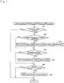
- Fig. 1 is a flowchart showing an entire routine of the control for engaging the starting clutch 3 in the event of restarting the engine 1 under the S & S control.
- the control is comprised of three modes for engaging the disengaging starting clutch 3. Therefore, the control mode to be shifted to is determined first of all. To this end, it is determined whether or not the starting clutch (also called the "clutch” in the following explanation) 3 is under control (at step S1). For example, if the starting clutch 3 is disengaged under the S & S control, or if the starting clutch 3 is being engaged gradually when starting the engine 1, the control system determines the fact that the starting clutch 3 is under control so that the answer of step S1 is YES.
- step S1 determines that the answer of step S1 will be NO.
- step S2 a satisfaction of the condition to restart the engine 1 is determined (at step S2). As described, the engine 1 is restarted under the S & S control upon satisfaction of the predetermined restarting condition. In other words, the engine 1 is restarted under the S & S control upon elimination of the predetermined stopping condition of the engine 1. Therefore, at step S2, a satisfaction of the restarting condition of the engine 1 is determined. If the answer of step S2 is YES, the clutch 3 is engaged to restart the engine 1.
- the control mode of the clutch 3 is shifted to a steady pressure (or low pressure) standby mode (at step S3).
- a steady pressure (or low pressure) standby mode at step S3.
- the friction clutch that is engaged by frictionally engaging friction plates is used as the clutch 3
- a clearance is created inevitably between the friction plates if the clutch is disengaged. That is, the clutch 3 starts transmitting torque when the clearance between the friction plates is reduced to zero.
- the torque transmitting capacity of the clutch 3 can be controlled after the clearance between the friction plates is reduced to zero. Therefore, under the steady pressure standby mode, a constant low pressure is applied to the clutch 3 in a manner such that the clearance between the friction plates is maintained substantially to zero.
- steady pressure standby control is carried out in the conventional automatic geared transmissions.
- step S4 it is determined whether or not a complete explosion of fuel is achieved in the engine 1 (at step S4). If the satisfaction of the condition to restart the engine 1 has already been determined so that the answer of step S2 is NO, the routine advances directly to step S4 while skipping step S3 to determine a complete explosion of fuel.
- a definition of the "complete explosion of fuel” is that the fuel is burnt completely in each cylinder so that the engine 1 is allowed to rotate autonomously. Specifically, the engine 1 is restarted by carrying out a motoring using a starter motor while restarting a fuel supply, and a crankshaft serving as the output shaft of the engine 1 is rotated at a predetermined angle or predetermined times until the complete explosion of fuel is achieved in the engine 1.
- step S4 it is determined whether or not the engine 1 starts rotating autonomously after such transitional state.
- the complete explosion of fuel is determined based on a fact that a number of revolutions of the engine 1 reaches a reference value determined according to a displacement and a type of the engine 1.
- a reference value of the engine speed is set within a range of 200 rpm to 500 rpm.
- an air-fuel mixture richer than a theoretical air-fuel ratio is delivered to the engine 1.
- the engine speed is increased toward a speed to be achieved in accordance with an opening degree of the accelerator or the throttle valve. Therefore, the clutch 3 is engaged to increase the torque transmitting capacity in accordance with such increase in the engine speed.
- the control mode is shifted to "engaging mode" (at step S5). Details of the engaging mode will be explained later.
- step S6 it is determined whether or not an engagement of the clutch 3 is completed (at step S6). If the complete explosion of fuel has already been determined so that the answer of step S4 is NO, the routine advances directly to step S6 while skipping step S5 to determine a completion of engagement of the clutch 3.
- a definition of the "completion of engagement” is that a difference between rotational speeds of an input (or drive) side member and an output (or driven) side member is eliminated. Therefore, the determination of step S6 can be made by comparing a rotational speed of the input side of the clutch 3, that is, a turbine speed of the torque converter 2 with a rotational speed of the input shaft of the transmission 4.
- step S6 If the clutch 3 has not yet been engaged completely so that the answer of step S6 is NO, the routine shown in Fig. 1 is returned to repeat the control from step S1. By contrast, if the answer of step S6 is YES, the control mode of the clutch 3 is shifted to "normal mode" (at step S7). Under the normal mode, the restarting of the engine 1 has been completed so that the engine 1 rotates autonomously, and a relation between an air intake of the engine 1 or a load represented by an throttle opening and an output torque converges to a predetermined relation.
- the torque transmitting capacity of the clutch 3 or the hydraulic pressure applied to the clutch 3 is controlled to be a capacity or a pressure obtained based on an output torque of the engine 1 calculated based on an engine load and an engine speed, and a speed ratio (or a torque ratio) of the torque converter 2.
- the above-explained controls to be carried out under the normal mode is known in the prior art as disclosed e.g., in Japanese Patent Laid-Open No. 11-325232 .
- step S5 of the preferred example the clutch 3 is controlled in the manner different from the known controls during a period from the complete explosion of fuel in the engine 1 to the completion of engagement of the clutch 3.
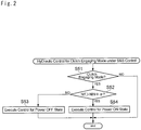
- the control to be carried out at step S5, that is, the control to be carried out under the clutch engaging mode will be explained hereinafter with reference to the flowchart shown in Fig. 2 .
- it is determined whether or not the control mode of the clutch 3 is shifted to the engaging mode (at step S51). For example, such determination at step S51 can be made by setting a flag at the aforementioned step S5, and determining if the flag is ON.
- step S52 it is determined whether or not the vehicle is bought into so-called a "power on" state (step S52). Provided that the vehicle is powered by the engine 1, torque of the engine 1 is transmitted to the input member of the clutch 3 through the torque converter 2, and the torque is further transmitted to the output member of the clutch 3 according to an engagement state of the clutch 3.
- a rotational speed of the output member of the clutch 3 that is, a rotational speed N IN of the input shaft of the transmission 4 is still lower than the turbine speed N T due to a slippage of the clutch 3. Accordingly, such speed difference is determined at step S52. Specifically, at step S52, it is determined whether or not the turbine speed N T is higher than a rotational speed calculated by adding a predetermined speed ⁇ to the rotational speed N IN of the input shaft of the transmission 4 (as will be simply called the "input speed" hereinafter). For this purpose, the predetermined speed ⁇ as a threshold value is determined at a design phase to determine a fact that the turbine speed N T exceeds the input speed N IN .
- the hydraulic pressure applied to the clutch 3 is increased according to a predetermined schedule.
- so called a "fast fill” is carried out to reduce a clearance between the friction plates of the clutch 3 by temporarily increasing the hydraulic pressure applied to the clutch 3, and duration of the fast fill and pressure to be applied to the clutch 3 are determined in advance.
- the pressure applied to the clutch 3 is increased at a predetermined rate determined in a manner not to cause shocks and not to keep the clutch 3 slipping excessively for a long period of time.
- the clutch 3 and the transmission 4 are powered by the torque of the engine 1.
- This situation may be categorized into the "power on state” and the control system judges as YES at step S52, and then, a hydraulic control of the clutch 3 for the power on state is carried out (at step S53). Details of the hydraulic control of the clutch 3 to be carried out under the power on state are shown in Fig. 3 .
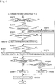
- an amount of change (or a change rate) ⁇ N E of the engine speed N E and an amount of change (or a change rate) ⁇ N T of the turbine speed N T are calculated (at step S541).
- Those amounts can be calculated by detecting each rotational speed N E and N T repeatedly at predetermined intervals, and calculating a difference between a prior detection value and a current detection value, or dividing the calculated value by an elapsed time from a prior detection to a current detection.
- the rotational speeds N E and N T are changed over time, and it takes some time to calculate.
- a capacity coefficient C representing characteristics of the torque converter 2 and a torque ratio t are changed in accordance with the speed ratio E. Therefore, the capacity coefficient C and the torque ratio t are then determined with reference to a map using the speed ratio E calculated at step S543 as a parameter (a step S544).
- a target amount of change (or a target change rate) ⁇ N Ttgt of the turbine speed N T is calculated.
- the target amount of change ⁇ N Ttgt is a target value of the turbine speed N T in the process of engaging the clutch 3 completely until the turbine speed N T is synchronized with the input speed N IN .
- the target amount of change ⁇ N Ttgt is preinstalled in the form of a map prepared taking account of shocks and a control delay.
- the target amount of change ⁇ N Ttgt of the turbine speed N T is determined using an engine load (i.e., a throttle opening), a vehicle speed and etc. as parameters.
- step S545 it is determined whether or not the engaging control of the clutch 3 for restarting the engine 1 is to be carried out. For example, if the clutch 3 has been disengaged under the S & S control but the condition to restart the engine 1 is satisfied or the condition to carry out the S & S control is eliminated before the engine 1 is stopped, the engaging control of the clutch 3 would be started while driving the engine 1. In other case, the engaging control of the clutch 3 may be carried out while restarting the engine 1 stopped by the S & S control responsive to a satisfaction of the restarting condition. At step S545, therefore, it is determined whether or not the clutch 3 is engaged while restarting the engine 1.
- step S545 the engine torque T e is calculated or estimated with reference to a map determining the engine torque T e using an air intake K I and the engine speed N E as parameters (at step S547).
- a map determining the engine torque T e using an air intake K I and the engine speed N E as parameters at step S547).
- the engine torque T e is calculated or estimated with reference to the map thus prepared.
- a torque T t of the turbine 8 of the torque converter 2 and an input torque T cl of the clutch 3 are calculated (at step S548).
- the turbine torque T t is calculated by applying a first order lag correction to the calculation value T tb .
- the turbine torque T t will not be applied to the clutch 3 as it is.
- a target pressure P cl with respect to the calculated input torque T cl is calculated.
- a base value P clb of the target pressure P cl for the clutch 3 is calculated (at step S549).
- the friction clutch is used as the clutch 3.
- the target pressure P cl for the clutch 3 is calculated based on the base value P clb thus calculated (at step S550).
- the target pressure P cl is calculated by correcting the base value P clb in accordance with an opening degree of the throttle valve, a speed ratio between the input side and the output side of the clutch 3, and so on.
- the correction coefficient ⁇ may be determined in advance with respect to the opening degree of the throttle valve, the speed ratio of the clutch 3 and so on, based on an result of an experimentation or a simulation carried out in a manner to suppress a change in shocks and acceleration at a final phase of the engagement of the clutch 3, or to avoid a delay in the engagement of the clutch 3. More specifically, the correction coefficient ⁇ is determined in a manner such that the target pressure P cl is lowered in case the opening degree of the throttle valve and the speed ratio of the clutch 3 are large, in comparison with the case in which the opening degree of the throttle valve and the speed ratio of the clutch 3 are small.
- Fig. 4 there are shown changes in the rotational speeds, the turbine torque T t , the target pressure P cl of the clutch 3 and so on.
- the determination to restart the engine 1 stopped by the S & S control is made (at point t1), the engine 1 is rotated by the starter motor and the rotational speed of the engine 1 is raised.
- the control mode of the clutch 3 is shifted to the steady pressure standby mode so that the target pressure P cl of the clutch 3 is raised temporarily to execute the fast fill, and the target pressure P d is then maintained to a low pressure level.
- Fig. 4 there are shown changes in the rotational speeds, the turbine torque T t , the target pressure P cl of the clutch 3 and so on.
- the transmission 4 is rotated by a torque from the driving wheels 6 side at a low speed, that is, the input speed N IN is low.
- the turbine 3 is rotated by a drag torque and the turbine speed N T is lower than the input speed N IN , that is, the vehicle is under the power off state.
- a combustion in the engine 1 is commenced by carrying out the motoring while delivering (or injecting) the fuel thereto so that the rotational speed of the engine 1 is increased.
- the complete combustion of fuel is determined (at point t2). Accordingly, the control mode of the clutch 3 is shifted to the engaging mode at the point t2.
- step S52 the negative determination is made at step S52 to carry out the control for the power off state. Specifically, the target pressure P cl of the clutch 3 is raised temporarily to execute the fast fill, and then maintained to a constant low pressure. Thereafter, the target pressure P cl is increased gradually.
- the turbine speed N T is increased gradually.
- the input speed N IN is maintained in accordance with the vehicle speed or the speed ratio of the transmission 4. Therefore, the turbine speed N T exceeds the input speed N IN in comparatively short time after the complete combustion of fuel in the engine 1.
- the determination of the power on state is made when a difference between the turbine speed N T and the input speed N IN exceeds the aforementioned predetermined speed ⁇ (at point t3), and the hydraulic control for the power on state explained with reference to Fig. 3 is carried out.
- the turbine torque T t is estimated (or calculated) based on the capacity coefficient C of the torque converter 2 and the torque ratio t by the procedure explained with reference to Fig. 3 .
- the turbine torque T t or the estimated value thereof is gradually increased from the point t2.
- the target value N Ttgt of the turbine speed N T is determined with reference to the map, and the target pressure P cl of the clutch 3 is determined to the value with respect to the estimated value of the turbine torque T t . Consequently, the actual pressure applied to the clutch 3 is increased gradually so that the torque transmitting capacity of the clutch 3 is increased gradually.
- the turbine speed N T is thus increased gradually in a manner to follow the target value N Ttgt so that the turbine speed N T is increased and eventually decreased at point t4 in Fig. 4 .
- a load torque applied to the engine 1 is increased with an increase in the torque transmitting capacity of the clutch 3 so that the engine speed N E is also decreased.
- the input speed N IN is increased. Therefore, the target amount of change (or the target change rate) ⁇ N Ttgt of the turbine speed N T is changed in a manner to synchronize the turbine speed N T with the input speed N IN being increased.
- the target amount of change (or the target change rate) ⁇ N Ttgt of the turbine speed N T is changed in a manner to synchronize the turbine speed N T with the input speed N IN being increased.
- the change rate is changed from the positive value to the negative value.
- the inertia torque is applied to the clutch 3. Therefore, the target pressure P cl of the clutch 3 is increased slightly stepwise, and then the turbine speed N T is changed gradually to achieve the target value N Ttgt thereof.
- the target pressure P cl of the hydraulic pressure applied to the clutch 3 is controlled based on the engine torque T e calculated based on the capacity coefficient C and the torque ratio t, until the starting clutch 3 is engaged completely. Therefore, the turbine speed N T and the engine speed N E are changed smoothly so that the drive torque is prevented from being changed abruptly and shocks are reduced.
- the clutch 3 is not simply caused to slip. This means that the clutch 3 is caused to slip during controlling the pressure applied to the clutch 3 in accordance with the engine torque T e to synchronize the turbine speed N T with the input speed N IN .
- a broken line represents a turbine torque calculated based on an engine load such as an air intake, without carrying out the foregoing controls of the preferred example. If the turbine torque is calculated based on an engine load and a speed ratio of the torque converter when restarting the engine 1, the turbine torque would be calculated based on an air intake increased to start the engine 1 certainly and a comparatively large speed ratio. Therefore, an estimated value of the turbine torque would be larger than an actual torque. If the torque to be applied to the clutch is controlled based on the larger estimated value, the clutch would be engaged abruptly while causing shocks. However, the control system according to the preferred example can avoid such occurrence of shocks certainly.
- Fig. 5 there is shown a flowchart in which the flowchart shown in Fig. 3 is partially modified.
- an amount of change (or a change rate) ⁇ N E of the engine speed N E and an amount of change (or a change rate) ⁇ N T of the turbine speed N T are calculated (at step S301) sequentially, and an estimated engine speed N E ' and an estimated turbine speed N T ' are individually calculated based on the calculated change rates ⁇ N E and ⁇ N T while taking account of calculation delay (at step S302).
- steps S301 to S304 are similar to steps S541 to S544 shown in Fig. 3 .
- step S307 an estimated value of the turbine torque T t is calculated based on those calculation values. Details of the control carried out at step S307 are shown in Fig. 6 . According to the subroutine carried out at step S307, first of all, it is determined whether or not the engaging control of the clutch 3 for restarting the engine 1 is to be carried out (at step S3071). That is, the determination similar to step S545 shown in Fig. 3 is carried out based on a signal from a not shown controller for the S & S control.
- step S3072 it is determined whether or not the accelerator is closed abruptly. In other words, it is determined whether or not the accelerator pedal is returned abruptly to reduce an opening degree of the accelerator to zero in short time. Such determination can be made based on a signal from an accelerator position censor. If the answer of step S3072 is YES, a flag for determining abrupt closing is set to ON (at step S3073). By contrast, if the answer of step S3072 is NO, it is determined whether or not the accelerator pedal is depressed (at step S3074). If the accelerator pedal is depressed so that the answer of step S3074 is YES, the flag for determining abrupt closing is set to OFF (at step S3075).
- step S3076 it is determined whether or not the estimated values T ecs and T ekl of the engine torque are close to each other (at step S3076). If the flag for determining abrupt closing was set to ON at step S3073, or if the accelerator pedal is not depressed so that the answer of step S3074 is NO, the routine advances directly to step S3076 to determine the relation between the estimated values Tecs and Tekl.
- the determination of a fact that the estimated values T ecs and T ekl are close to each other can be made by determining an absolute value of a difference between the estimated values T ecs and T ekl is smaller than a predetermined criterion value T0.
- the criterion value T0 is determined in a manner such that a variation width of the drive torque falls within an allowable width, even if the estimated value of the engine torque T e used to control the pressure applied to the clutch is altered from the estimated value T ecs calculated based on the characteristics of the torque converter 2 to the estimated value T ekl calculated based on the air intake.
- step S3076 If the estimated values T ecs and T ekl are close to each other so that the answer of step S3076 is YES, a flag for determining proximity of the engine torque T e is set to ON (at step S3077). By contrast, if the difference between the estimated values T ecs and T ekl is larger than the criterion value T0 so that the answer of step S3076 is NO, the flag for determining proximity of the engine torque Te is set to OFF (at step S3078).
- step S3079 After carrying out any of the controls of steps S3077 and S3078, it is determined whether or not the flag for determining abrupt closing is set to ON (at step S3079). Specifically, if the accelerator pedal was returned abruptly after the commencement of the control to restart the engine 1 so that the flag for determining abrupt closing has been set to ON, the answer of step S3079 will be YES. By contrast, if the accelerator pedal has not been returned abruptly since the commencement of the control to restart the engine 1, the answer of step S3079 will be NO. If the answer of step S3079 is YES, then it is determined whether or not the flag for determining proximity of the engine torque T e is set to ON (at step S3080).
- a base value T tb of the turbine torque T t is calculated by multiplying the estimated value T ecs obtained based on the capacity coefficient C of the torque converter 2 by the torque ratio t (at step S3081).
- step S3080 if the answer of step S3080 is YES, that is, if the accelerator pedal has been returned abruptly, and the estimated values T ecs and T ekl are close to each other, the base value T tb of the turbine torque T t is calculated by multiplying the estimated value T ekl obtained based on the air intake K I by the torque ratio t (at step S3082). Then, the turbine torque T t is calculated by applying a first order lag correction to the calculated base value T tb .
- the estimated value of the turbine torque T t is calculated by the above-explained procedures at step S307, and then it is determined whether or not the engine speed is increased abruptly so that a difference between an input speed and an output speed of the clutch 3 is widened (at step S308). For example, such determination can be made based on a difference between: a minimum value N Tmin of a difference between the turbine speed N T and the input speed N IN after shifting the control mode of the hydraulic pressure applied to the clutch 3 to the engaging mode; and a current difference between the turbine speed N T and the input speed N IN .
- control system determines a fact that the engine speed is increased abruptly given that the difference between the current difference between the turbine speed N T and the input speed N IN and the minimum value N Tmin is larger than a predetermined value (((N T - N IN ) - (N T - N IN ) min ) > predetermined value).
- step S308 If the difference between the turbine speed N T and the input speed N IN is being reduced with the progress of the control of the hydraulic pressure applied of the clutch 3, the answer of step S308 will be NO.
- a target amount of change ⁇ N Ttgt of the turbine speed N T is determined with reference to the preinstalled map in which a throttle opening, a vehicle speed and etc. are used as parameters so as to synchronize the turbine speed N T with the input speed N IN being increased (at step S309).
- a target amount of change ⁇ N Ttgt of the turbine speed N T is determined with reference to the preinstalled map in which a throttle opening, a vehicle speed and etc. are used as parameters so as to synchronize the turbine speed N T with the input speed N IN being increased (at step S309).
- an engine torque is transmitted to the clutch 3 under a condition that the pressure applied to the clutch 3 is still low, and the turbine speed N T and the input speed N IN may be large.
- step S308 will be YES in the beginning of the control of the hydraulic pressure applied to the clutch 3.
- a target base value P clb of the hydraulic pressure applied to the clutch 3 is calculated based on the target clutch torque T cl (at step S314), and a target pressure P cl is calculated (at step S315).
- the calculations similar to those executed at the aforementioned steps S549 and S550 shown in Fig. 3 are also carried out at steps S314 and S315.
- Fig. 7 shows an example in which the brake pedal is returned under the deceleration-based S & S control so that the control to restart the engine 1 is commenced, and then the accelerator pedal is temporarily depressed and immediately returned.
- the brake pedal is returned, the determination to restart the engine 1 is made (at point t1), and the control mode of the clutch 3 is shifted to the steady pressure standby mode.
- the accelerator pedal is depressed so that the vehicle is brought into the power on state, and then, the complete combustion of fuel is determined (at point t2). Then, the determination of the power on state is made (at point t3), and the pressure applied to the clutch 3 is increased gradually and the turbine speed N T starts lowering so that the determination to lower the engine speed is made (at point t4).
- the rotational speeds, the torque, and the hydraulic pressure applied to the clutch 3 are changed in a manner similar to those in the example shown in Fig. 4 until the point t4.
- the engine torque value used to control the hydraulic pressure applied to the clutch 3 is shifted from the estimated engine torque T ecs estimated from the capacity coefficient C of the torque converter 2 to the estimated engine torque T ekl estimated from the air intake K I , based on a fact that the estimated engine torque T ecs and the estimated engine torque T ekl are close to each other.
- the estimated engine torque T ekl is reduced rapidly by returning the accelerator pedal to reduce the opening degree of the throttle valve to zero. Consequently, the hydraulic pressure applied to the clutch 3 is reduced promptly with the reduction in the estimated engine torque T ekl estimated from the air intake K I .
- the torque transmitted to the driving wheels 6 is reduced so that the longitudinal acceleration of the vehicle is reduced without delay behind the returning operation of the accelerator pedal. That is, the vehicle is decelerated or allowed to coast.
- the opening degree of the throttle valve is reduced to zero at point t6, and the longitudinal acceleration is immediately reduced to be negative at point t7. Therefore, a period of so-called "free running", that is, a period of producing the longitudinal acceleration after returning the accelerator pedal can be shortened thereby reducing an uncomfortable feeling which may felt by the driver. If the control to deal with the abrupt closing is not carried out, the estimated turbine torque would be changed as indicated by a solid line in Fig. 7 .
- the estimated turbine torque is reduced to zero after the point t5 at which the determination of termination of the engagement. Therefore, the hydraulic pressure is maintained to a high level to produce the longitudinal acceleration positively. As a result, a period of free running is extended to provide an uncomfortable feeling.
- the target turbine speed N Ttgt is calculated based on the engine speed N E or the estimated value N E ' thereof. Therefore, the target turbine speed N Ttgt is allowed to be changed smoothly before and after the determination to lower the engine speed. For this reason, the hydraulic pressure applied to the clutch will not be changed stepwise so that the drive torque can be prevented from being changed stepwise to cause shocks.
- a clutch that is controlled electrically to change a torque transmitting capacity may also be used as the starting clutch instead of the clutch that is controlled hydraulically to change a torque transmitting capacity.
- a current applied to the clutch is controlled instead of hydraulic pressure to change the torque transmitting capacity of the clutch.
- the starting clutch control system is applied to a vehicle in which a torque generated by an engine is inputted to a torque converter comprised of a pump impeller and a turbine, and the torque is outputted from the torque converter to driving wheels through a starting clutch, and the foregoing controls are executed by an electronic control unit composed mainly of a microcomputer that is configured to stop the engine while disengaging the starting clutch upon satisfaction of a predetermined condition when the vehicle is running, and to restart the stopping engine while engaging the starting clutch upon satisfaction of a predetermined restarting condition.
- the starting clutch control system is comprised of: a first turbine torque estimating means that estimates a torque of a turbine of the torque converter based on an engine speed, and a capacity coefficient and a torque ratio of the torque converter, when the engine is required to increase a power to be restarted; a torque transmitting capacity increasing means that increases a torque transmitting capacity of the clutch in accordance with the estimated torque of the turbine; and a second turbine torque estimating means that estimates the torque of the turbine based on an air intake of the engine and the engine speed after a completion of an engagement of the clutch.
- the starting clutch control system is configured to control the torque transmitting capacity of the clutch in accordance with the torque of the turbine estimated based on the air intake of the engine and the engine speed instead of the torque estimated based on the engine speed, and the capacity coefficient and the torque ratio of the torque converter, if a demand to increase the engine power is eliminated during increasing the torque transmitting capacity of the clutch.
Landscapes
- Engineering & Computer Science (AREA)
- General Engineering & Computer Science (AREA)
- Mechanical Engineering (AREA)
- Combustion & Propulsion (AREA)
- Chemical & Material Sciences (AREA)
- Fluid Mechanics (AREA)
- Physics & Mathematics (AREA)
- Transportation (AREA)
- Control Of Transmission Device (AREA)
- Hydraulic Clutches, Magnetic Clutches, Fluid Clutches, And Fluid Joints (AREA)
- Control Of Driving Devices And Active Controlling Of Vehicle (AREA)
- Control Of Vehicle Engines Or Engines For Specific Uses (AREA)
- Control Of Fluid Gearings (AREA)
Claims (7)
- Anfahrkupplungssteuerungssystem, das bei einem Fahrzeug eingesetzt wird, bei dem ein durch eine Maschine (1) erzeugtes Drehmoment in einen aus einem Pumpenlaufrad (7) und einer Turbine (8) bestehenden Drehmomentwandler (2) eingegeben wird und das Drehmoment von dem Drehmomentwandler (2) zu Antriebsrädern (6) durch eine Anfahrkupplung (3) ausgegeben wird, und das eingerichtet ist, die Maschine (1) zu stoppen, während die Anfahrkupplung (3) gelöst ist, bei einem Erfüllen einer vorbestimmten Bedingung, wenn das Fahrzeug fährt, und die angehaltene Maschine (1) wieder zu starten, während die Anfahrkupplung (3) in Eingriff ist, bei einem Erfüllen einer vorbestimmten Wiederstartbedingung, wobei
das Anfahrkupplungssteuerungssystem eingerichtet ist,
ein Drehmoment (Tt) der Turbine (8) des Drehmomentwandlers (2) basierend auf einer Maschinendrehzahl (NE) und einem Kapazitätskoeffizienten (C), und einem Drehmomentverhältnis (t) des Drehmomentwandlers (2) zu schätzen, wenn die Maschine (1) eine Leistung erhöhen muss, um wieder gestartet zu werden; und dadurch gekennzeichnet ist, dass das System ferner eingerichtet ist:eine Drehmomentübertragungskapazität der Anfahrkupplung (3) in Übereinstimmung mit dem geschätzten Drehmoment (Tt) der Turbine (8) zu erhöhen;das Drehmoment (Tt) der Turbine (8) basierend auf einer Luftansaugung (KI) der Maschine (1) und der Maschinendrehzahl (NE) nach einem Abschluss eines Eingriffs der Anfahrkupplung (3) zu schätzen; unddie Drehmomentübertragungskapazität der Anfahrkupplung (3) in Übereinstimmung mit dem geschätzten Drehmoment (Tt) der Turbine (8) zu steuern. - Anfahrkupplungssteuerungssystem nach Anspruch 1,
wobei das Anfahrkupplungssteuerungssystem ferner eingerichtet ist, die Drehmomentübertragungskapazität der Anfahrkupplung (3) in Übereinstimmung mit dem Drehmoment (Tt) der Turbine (8), das basierend auf der Luftansaugung (KI) der Maschine (1) und der Maschinendrehzahl (NE) geschätzt ist, anstatt dem Drehmoment (Tt) der Turbine (8) zu steuern, das basierend auf der Maschinendrehzahl (NE) und dem Kapazitätskoeffizienten (C), und dem Drehmomentverhältnis (t) des Drehmomentwandlers (2) geschätzt ist, wenn eine Anforderung, eine Leistung der Maschine (1) zu erhöhen, während einer Erhöhung der Drehmomentübertragungskapazität der Anfahrkupplung (3) beseitigt wird. - Anfahrkupplungssteuerungssystem nach Anspruch 2,
wobei das Drehmoment (Tt) der Turbine (8), das zum Steuern der Drehmomentübertragungskapazität der Anfahrkupplung (3) verwendet werden soll, von dem Drehmoment (Tt) der Turbine (8), das basierend auf der Maschinendrehzahl (NE) und dem Kapazitätskoeffizienten (C), und dem Drehmomentverhältnis (t) des Drehmomentwandlers (2) geschätzt ist, zu dem Drehmoment (Tt) der Turbine (8) umgeschaltet wird, das basierend auf der Luftansaugung (KI) der Maschine (1) und der Maschinendrehzahl (NE) geschätzt ist, wenn eine Differenz zwischen diesen geschätzten Drehmomenten kleiner ist als ein vorbestimmter Wert. - Anfahrkupplungssteuerungssystem nach einem der Ansprüche 1 bis 3,
wobei die Anfahrkupplung (3) eine Reibkupplung umfasst, deren Drehmomentübertragungskapazität erhöht wird, indem ein an diese angelegter hydraulischer Druck erhöht wird; und
wobei der an die Reibkupplung angelegte hydraulische Druck in Übereinstimmung mit einem Öffnungsgrad eines Drosselventils des Fahrzeugs oder einem Drehzahlverhältnis der Reibkupplung korrigiert wird. - Anfahrkupplungssteuerungssystem nach Anspruch 4,
wobei die Korrektur eine Korrektur umfasst, um den Hydraulikdruck in dem Fall zu verringern, in dem der Öffnungsgrad des Drosselventils oder das Drehzahlverhältnis groß ist, verglichen mit einem Fall, in dem der Öffnungsgrad des Drosselventils oder das Drehzahlverhältnis klein ist. - Anfahrkupplungssteuerungssystem nach einem der Ansprüche 1 bis 5,
wobei die Maschine (1) eine Brennkraftmaschine (1) umfasst; und
wobei das Anfahrkupplungssteuerungssystem ferner eingerichtet ist, das Drehmoment (Tt) der Turbine (8) des Drehmomentwandlers (2) basierend auf der Maschinendrehzahl (NE) und dem Kapazitätskoeffizienten (C), und dem Drehmomentverhältnis (t) des Drehmomentwandlers (2) zu schätzen, nachdem eine vollständige Explosion eines Kraftstoffs in der wieder gestarteten Maschine (1) erreicht ist; und
die Drehmomentübertragungskapazität der Anfahrkupplung (3) in Übereinstimmung mit dem geschätzten Drehmoment (Tt) der Turbine (8) zu erhöhen. - Anfahrkupplungssteuerungssystem nach einem der Ansprüche 1 bis 5,
wobei die Anforderung die Leistung der Maschine (1) zu erhöhen eine Zunahme des Öffnungsgrades des Fahrpedals oder des Drosselventils umfasst.
Applications Claiming Priority (1)
| Application Number | Priority Date | Filing Date | Title |
|---|---|---|---|
| PCT/JP2012/059499 WO2013150641A1 (ja) | 2012-04-06 | 2012-04-06 | 車両の発進クラッチ制御装置 |
Publications (3)
| Publication Number | Publication Date |
|---|---|
| EP2835552A1 EP2835552A1 (de) | 2015-02-11 |
| EP2835552A4 EP2835552A4 (de) | 2017-01-11 |
| EP2835552B1 true EP2835552B1 (de) | 2017-11-29 |
Family
ID=49300163
Family Applications (1)
| Application Number | Title | Priority Date | Filing Date |
|---|---|---|---|
| EP12873833.3A Active EP2835552B1 (de) | 2012-04-06 | 2012-04-06 | Vorrichtung zur steuerung von startkupplungen für fahrzeuge |
Country Status (5)
| Country | Link |
|---|---|
| US (1) | US9353807B2 (de) |
| EP (1) | EP2835552B1 (de) |
| JP (1) | JP5839115B2 (de) |
| CN (1) | CN104204589B (de) |
| WO (1) | WO2013150641A1 (de) |
Families Citing this family (14)
| Publication number | Priority date | Publication date | Assignee | Title |
|---|---|---|---|---|
| WO2016208360A1 (ja) * | 2015-06-25 | 2016-12-29 | 日立オートモティブシステムズ株式会社 | 車載制御装置 |
| US9945474B2 (en) * | 2015-09-29 | 2018-04-17 | Deere & Company | Shift control for an automatic transmission |
| KR101714231B1 (ko) * | 2015-10-02 | 2017-03-09 | 현대자동차주식회사 | 차량의 발진 제어방법 |
| JP6599227B2 (ja) * | 2015-12-25 | 2019-10-30 | ダイハツ工業株式会社 | 自動変速機の制御装置 |
| JP2017129257A (ja) * | 2016-01-22 | 2017-07-27 | トヨタ自動車株式会社 | 車両用動力伝達装置の制御装置 |
| US9850965B2 (en) * | 2016-05-03 | 2017-12-26 | Ford Global Technologies, Llc | Method for operating an automatic start/stop system in a vehicle utilizing a fluid launch clutch |
| US10017182B2 (en) * | 2016-06-28 | 2018-07-10 | Ford Global Technologies, Llc | System and method for controlling a torque converter clutch |
| CN111465758B (zh) * | 2017-11-22 | 2022-02-25 | 日产自动车株式会社 | 内燃机的控制方法以及内燃机的控制装置 |
| CN112677958B (zh) * | 2021-01-08 | 2022-08-09 | 重庆长安汽车股份有限公司 | 一种车辆起步控制方法、系统及车辆 |
| CN112937583B (zh) * | 2021-03-19 | 2022-06-03 | 重庆长安汽车股份有限公司 | 一种车辆低温起步控制方法及计算机可存储介质 |
| CN115388105B (zh) * | 2021-05-24 | 2025-08-05 | 上海汽车集团股份有限公司 | 离合器扭矩的控制方法 |
| KR20230090470A (ko) * | 2021-12-15 | 2023-06-22 | 현대자동차주식회사 | 하이브리드 차량의 제어 방법 |
| CN114962493B (zh) * | 2022-06-01 | 2024-03-19 | 潍柴动力股份有限公司 | Pto离合器的控制方法及设备、计算机程序产品 |
| DE102022213793B4 (de) * | 2022-12-16 | 2024-07-25 | Zf Friedrichshafen Ag | System und Verfahren zum Betreiben einer Arbeitsmaschine |
Family Cites Families (19)
| Publication number | Priority date | Publication date | Assignee | Title |
|---|---|---|---|---|
| US5403249A (en) * | 1991-10-07 | 1995-04-04 | Eaton Corporation | Method and apparatus for robust automatic clutch control |
| JP3260190B2 (ja) * | 1993-01-08 | 2002-02-25 | 株式会社日立製作所 | 自動車の出力軸トルク推定装置及び車重算出装置 |
| GB9402252D0 (en) * | 1994-02-05 | 1994-03-30 | Automotive Products Plc | Clutch control system |
| GB9421324D0 (en) * | 1994-10-22 | 1994-12-07 | Automotive Products Plc | Clutch control system |
| JPH11325232A (ja) | 1998-03-19 | 1999-11-26 | Hitachi Ltd | 自動変速機のクラッチ油圧の制御装置と制御方法 |
| JP4274681B2 (ja) * | 2000-09-08 | 2009-06-10 | ダイハツ工業株式会社 | 発進クラッチのクリープ力制御方法 |
| JP4648587B2 (ja) * | 2001-07-18 | 2011-03-09 | 本田技研工業株式会社 | 動力伝達装置におけるエンジン再始動発進制御装置 |
| JP4394386B2 (ja) * | 2003-07-07 | 2010-01-06 | アイシン精機株式会社 | クラッチ制御装置 |
| CN100470074C (zh) * | 2003-10-24 | 2009-03-18 | 株式会社小松制作所 | 发动机动力传递装置及其方法 |
| US7188017B2 (en) * | 2004-02-09 | 2007-03-06 | Ford Global Technologies, Llc | Method and apparatus for controlling a transfer case clutch to improve vehicle handling |
| JP2005291174A (ja) | 2004-04-05 | 2005-10-20 | Denso Corp | 車両用エンジンのトルク制御装置 |
| DE102004016846A1 (de) * | 2004-04-07 | 2005-10-27 | Zf Friedrichshafen Ag | Steuerungssystem für ein Fahrzeuggetriebe |
| US7370715B2 (en) * | 2004-12-28 | 2008-05-13 | Ford Global Technologies, Llc | Vehicle and method for controlling engine start in a vehicle |
| JP4358130B2 (ja) * | 2005-02-22 | 2009-11-04 | ジヤトコ株式会社 | 自動変速機の油圧制御装置 |
| JP4626553B2 (ja) * | 2006-03-30 | 2011-02-09 | アイシン・エィ・ダブリュ株式会社 | 発進装置の制御装置 |
| JP2008298100A (ja) * | 2007-05-29 | 2008-12-11 | Hitachi Ltd | 自動変速機の発進クラッチ制御装置および制御方法 |
| JP2009047272A (ja) * | 2007-08-22 | 2009-03-05 | Aisin Aw Co Ltd | ロックアップクラッチ付き流体伝動装置 |
| JP5493699B2 (ja) * | 2009-10-23 | 2014-05-14 | アイシン精機株式会社 | 車両制御装置 |
| JP5377352B2 (ja) * | 2010-02-05 | 2013-12-25 | トヨタ自動車株式会社 | 車両用動力伝達装置の発進制御装置 |
-
2012
- 2012-04-06 US US14/375,242 patent/US9353807B2/en active Active
- 2012-04-06 CN CN201280071985.6A patent/CN104204589B/zh active Active
- 2012-04-06 EP EP12873833.3A patent/EP2835552B1/de active Active
- 2012-04-06 JP JP2014508976A patent/JP5839115B2/ja active Active
- 2012-04-06 WO PCT/JP2012/059499 patent/WO2013150641A1/ja not_active Ceased
Also Published As
| Publication number | Publication date |
|---|---|
| JP5839115B2 (ja) | 2016-01-06 |
| EP2835552A4 (de) | 2017-01-11 |
| CN104204589B (zh) | 2017-03-08 |
| US20150133267A1 (en) | 2015-05-14 |
| WO2013150641A1 (ja) | 2013-10-10 |
| JPWO2013150641A1 (ja) | 2015-12-14 |
| EP2835552A1 (de) | 2015-02-11 |
| CN104204589A (zh) | 2014-12-10 |
| US9353807B2 (en) | 2016-05-31 |
Similar Documents
| Publication | Publication Date | Title |
|---|---|---|
| EP2835552B1 (de) | Vorrichtung zur steuerung von startkupplungen für fahrzeuge | |
| US8326475B2 (en) | Hybrid drive device | |
| US7150333B2 (en) | Vehicle control apparatus and method | |
| US8738217B2 (en) | Methods and systems for a hybrid vehicle | |
| US8292782B2 (en) | Control apparatus for belt-type continuously-variable transmission | |
| US8924070B2 (en) | Methods and systems for a hybrid vehicle | |
| US6389348B1 (en) | Control system for vehicle having continuously variable transmission | |
| EP2865913A1 (de) | Fahrzeugsteuerung | |
| EP2689980A1 (de) | Getriebesteuerungsvorrichtung für ein hybridfahrzeug | |
| US7356400B2 (en) | Clutch control apparatus and method | |
| US11041451B2 (en) | Internal combustion engine control method and internal combustion engine control device | |
| US7704189B2 (en) | Starting method for internal combustion engines with a double clutch transmission | |
| JP2005214331A (ja) | クラッチ制御装置 | |
| US9933026B2 (en) | Vehicle control system | |
| US10295001B2 (en) | Control device of lock-up clutch | |
| JP5556576B2 (ja) | ハイブリッド車両の制御装置 | |
| JP5880355B2 (ja) | 車両の発進クラッチ制御装置 | |
| JP6942558B2 (ja) | ハイブリッド車両の制御方法 | |
| JP4023157B2 (ja) | 自動変速機の制御装置 | |
| JP5776612B2 (ja) | 車両の発進クラッチ制御装置 |
Legal Events
| Date | Code | Title | Description |
|---|---|---|---|
| PUAI | Public reference made under article 153(3) epc to a published international application that has entered the european phase |
Free format text: ORIGINAL CODE: 0009012 |
|
| 17P | Request for examination filed |
Effective date: 20140808 |
|
| AK | Designated contracting states |
Kind code of ref document: A1 Designated state(s): AL AT BE BG CH CY CZ DE DK EE ES FI FR GB GR HR HU IE IS IT LI LT LU LV MC MK MT NL NO PL PT RO RS SE SI SK SM TR |
|
| AX | Request for extension of the european patent |
Extension state: BA ME |
|
| DAX | Request for extension of the european patent (deleted) | ||
| RA4 | Supplementary search report drawn up and despatched (corrected) |
Effective date: 20161214 |
|
| RIC1 | Information provided on ipc code assigned before grant |
Ipc: F16D 48/08 20060101ALI20161208BHEP Ipc: F16D 48/02 20060101AFI20161208BHEP |
|
| GRAP | Despatch of communication of intention to grant a patent |
Free format text: ORIGINAL CODE: EPIDOSNIGR1 |
|
| RIC1 | Information provided on ipc code assigned before grant |
Ipc: F16D 48/08 20060101ALI20170531BHEP Ipc: F16D 48/02 20060101AFI20170531BHEP |
|
| INTG | Intention to grant announced |
Effective date: 20170629 |
|
| GRAS | Grant fee paid |
Free format text: ORIGINAL CODE: EPIDOSNIGR3 |
|
| GRAA | (expected) grant |
Free format text: ORIGINAL CODE: 0009210 |
|
| AK | Designated contracting states |
Kind code of ref document: B1 Designated state(s): AL AT BE BG CH CY CZ DE DK EE ES FI FR GB GR HR HU IE IS IT LI LT LU LV MC MK MT NL NO PL PT RO RS SE SI SK SM TR |
|
| REG | Reference to a national code |
Ref country code: CH Ref legal event code: EP |
|
| REG | Reference to a national code |
Ref country code: AT Ref legal event code: REF Ref document number: 950669 Country of ref document: AT Kind code of ref document: T Effective date: 20171215 |
|
| REG | Reference to a national code |
Ref country code: IE Ref legal event code: FG4D |
|
| REG | Reference to a national code |
Ref country code: DE Ref legal event code: R096 Ref document number: 602012040462 Country of ref document: DE |
|
| REG | Reference to a national code |
Ref country code: FR Ref legal event code: PLFP Year of fee payment: 7 |
|
| REG | Reference to a national code |
Ref country code: NL Ref legal event code: MP Effective date: 20171129 |
|
| REG | Reference to a national code |
Ref country code: LT Ref legal event code: MG4D |
|
| REG | Reference to a national code |
Ref country code: AT Ref legal event code: MK05 Ref document number: 950669 Country of ref document: AT Kind code of ref document: T Effective date: 20171129 |
|
| PG25 | Lapsed in a contracting state [announced via postgrant information from national office to epo] |
Ref country code: FI Free format text: LAPSE BECAUSE OF FAILURE TO SUBMIT A TRANSLATION OF THE DESCRIPTION OR TO PAY THE FEE WITHIN THE PRESCRIBED TIME-LIMIT Effective date: 20171129 Ref country code: LT Free format text: LAPSE BECAUSE OF FAILURE TO SUBMIT A TRANSLATION OF THE DESCRIPTION OR TO PAY THE FEE WITHIN THE PRESCRIBED TIME-LIMIT Effective date: 20171129 Ref country code: ES Free format text: LAPSE BECAUSE OF FAILURE TO SUBMIT A TRANSLATION OF THE DESCRIPTION OR TO PAY THE FEE WITHIN THE PRESCRIBED TIME-LIMIT Effective date: 20171129 Ref country code: SE Free format text: LAPSE BECAUSE OF FAILURE TO SUBMIT A TRANSLATION OF THE DESCRIPTION OR TO PAY THE FEE WITHIN THE PRESCRIBED TIME-LIMIT Effective date: 20171129 Ref country code: NO Free format text: LAPSE BECAUSE OF FAILURE TO SUBMIT A TRANSLATION OF THE DESCRIPTION OR TO PAY THE FEE WITHIN THE PRESCRIBED TIME-LIMIT Effective date: 20180228 |
|
| PG25 | Lapsed in a contracting state [announced via postgrant information from national office to epo] |
Ref country code: HR Free format text: LAPSE BECAUSE OF FAILURE TO SUBMIT A TRANSLATION OF THE DESCRIPTION OR TO PAY THE FEE WITHIN THE PRESCRIBED TIME-LIMIT Effective date: 20171129 Ref country code: LV Free format text: LAPSE BECAUSE OF FAILURE TO SUBMIT A TRANSLATION OF THE DESCRIPTION OR TO PAY THE FEE WITHIN THE PRESCRIBED TIME-LIMIT Effective date: 20171129 Ref country code: BG Free format text: LAPSE BECAUSE OF FAILURE TO SUBMIT A TRANSLATION OF THE DESCRIPTION OR TO PAY THE FEE WITHIN THE PRESCRIBED TIME-LIMIT Effective date: 20180228 Ref country code: GR Free format text: LAPSE BECAUSE OF FAILURE TO SUBMIT A TRANSLATION OF THE DESCRIPTION OR TO PAY THE FEE WITHIN THE PRESCRIBED TIME-LIMIT Effective date: 20180301 Ref country code: RS Free format text: LAPSE BECAUSE OF FAILURE TO SUBMIT A TRANSLATION OF THE DESCRIPTION OR TO PAY THE FEE WITHIN THE PRESCRIBED TIME-LIMIT Effective date: 20171129 Ref country code: AT Free format text: LAPSE BECAUSE OF FAILURE TO SUBMIT A TRANSLATION OF THE DESCRIPTION OR TO PAY THE FEE WITHIN THE PRESCRIBED TIME-LIMIT Effective date: 20171129 |
|
| PG25 | Lapsed in a contracting state [announced via postgrant information from national office to epo] |
Ref country code: NL Free format text: LAPSE BECAUSE OF FAILURE TO SUBMIT A TRANSLATION OF THE DESCRIPTION OR TO PAY THE FEE WITHIN THE PRESCRIBED TIME-LIMIT Effective date: 20171129 |
|
| PG25 | Lapsed in a contracting state [announced via postgrant information from national office to epo] |
Ref country code: SK Free format text: LAPSE BECAUSE OF FAILURE TO SUBMIT A TRANSLATION OF THE DESCRIPTION OR TO PAY THE FEE WITHIN THE PRESCRIBED TIME-LIMIT Effective date: 20171129 Ref country code: CY Free format text: LAPSE BECAUSE OF FAILURE TO SUBMIT A TRANSLATION OF THE DESCRIPTION OR TO PAY THE FEE WITHIN THE PRESCRIBED TIME-LIMIT Effective date: 20171129 Ref country code: EE Free format text: LAPSE BECAUSE OF FAILURE TO SUBMIT A TRANSLATION OF THE DESCRIPTION OR TO PAY THE FEE WITHIN THE PRESCRIBED TIME-LIMIT Effective date: 20171129 Ref country code: DK Free format text: LAPSE BECAUSE OF FAILURE TO SUBMIT A TRANSLATION OF THE DESCRIPTION OR TO PAY THE FEE WITHIN THE PRESCRIBED TIME-LIMIT Effective date: 20171129 Ref country code: CZ Free format text: LAPSE BECAUSE OF FAILURE TO SUBMIT A TRANSLATION OF THE DESCRIPTION OR TO PAY THE FEE WITHIN THE PRESCRIBED TIME-LIMIT Effective date: 20171129 |
|
| REG | Reference to a national code |
Ref country code: DE Ref legal event code: R097 Ref document number: 602012040462 Country of ref document: DE |
|
| PG25 | Lapsed in a contracting state [announced via postgrant information from national office to epo] |
Ref country code: SM Free format text: LAPSE BECAUSE OF FAILURE TO SUBMIT A TRANSLATION OF THE DESCRIPTION OR TO PAY THE FEE WITHIN THE PRESCRIBED TIME-LIMIT Effective date: 20171129 Ref country code: PL Free format text: LAPSE BECAUSE OF FAILURE TO SUBMIT A TRANSLATION OF THE DESCRIPTION OR TO PAY THE FEE WITHIN THE PRESCRIBED TIME-LIMIT Effective date: 20171129 Ref country code: RO Free format text: LAPSE BECAUSE OF FAILURE TO SUBMIT A TRANSLATION OF THE DESCRIPTION OR TO PAY THE FEE WITHIN THE PRESCRIBED TIME-LIMIT Effective date: 20171129 |
|
| REG | Reference to a national code |
Ref country code: DE Ref legal event code: R084 Ref document number: 602012040462 Country of ref document: DE |
|
| PLBE | No opposition filed within time limit |
Free format text: ORIGINAL CODE: 0009261 |
|
| STAA | Information on the status of an ep patent application or granted ep patent |
Free format text: STATUS: NO OPPOSITION FILED WITHIN TIME LIMIT |
|
| REG | Reference to a national code |
Ref country code: GB Ref legal event code: 746 Effective date: 20180927 |
|
| 26N | No opposition filed |
Effective date: 20180830 |
|
| PG25 | Lapsed in a contracting state [announced via postgrant information from national office to epo] |
Ref country code: SI Free format text: LAPSE BECAUSE OF FAILURE TO SUBMIT A TRANSLATION OF THE DESCRIPTION OR TO PAY THE FEE WITHIN THE PRESCRIBED TIME-LIMIT Effective date: 20171129 Ref country code: MC Free format text: LAPSE BECAUSE OF FAILURE TO SUBMIT A TRANSLATION OF THE DESCRIPTION OR TO PAY THE FEE WITHIN THE PRESCRIBED TIME-LIMIT Effective date: 20171129 |
|
| REG | Reference to a national code |
Ref country code: CH Ref legal event code: PL |
|
| REG | Reference to a national code |
Ref country code: BE Ref legal event code: MM Effective date: 20180430 |
|
| REG | Reference to a national code |
Ref country code: IE Ref legal event code: MM4A |
|
| PG25 | Lapsed in a contracting state [announced via postgrant information from national office to epo] |
Ref country code: LU Free format text: LAPSE BECAUSE OF NON-PAYMENT OF DUE FEES Effective date: 20180406 |
|
| PG25 | Lapsed in a contracting state [announced via postgrant information from national office to epo] |
Ref country code: LI Free format text: LAPSE BECAUSE OF NON-PAYMENT OF DUE FEES Effective date: 20180430 Ref country code: BE Free format text: LAPSE BECAUSE OF NON-PAYMENT OF DUE FEES Effective date: 20180430 Ref country code: CH Free format text: LAPSE BECAUSE OF NON-PAYMENT OF DUE FEES Effective date: 20180430 |
|
| PG25 | Lapsed in a contracting state [announced via postgrant information from national office to epo] |
Ref country code: IE Free format text: LAPSE BECAUSE OF NON-PAYMENT OF DUE FEES Effective date: 20180406 |
|
| PG25 | Lapsed in a contracting state [announced via postgrant information from national office to epo] |
Ref country code: MT Free format text: LAPSE BECAUSE OF NON-PAYMENT OF DUE FEES Effective date: 20180406 |
|
| PG25 | Lapsed in a contracting state [announced via postgrant information from national office to epo] |
Ref country code: TR Free format text: LAPSE BECAUSE OF FAILURE TO SUBMIT A TRANSLATION OF THE DESCRIPTION OR TO PAY THE FEE WITHIN THE PRESCRIBED TIME-LIMIT Effective date: 20171129 |
|
| PG25 | Lapsed in a contracting state [announced via postgrant information from national office to epo] |
Ref country code: HU Free format text: LAPSE BECAUSE OF FAILURE TO SUBMIT A TRANSLATION OF THE DESCRIPTION OR TO PAY THE FEE WITHIN THE PRESCRIBED TIME-LIMIT; INVALID AB INITIO Effective date: 20120406 Ref country code: PT Free format text: LAPSE BECAUSE OF FAILURE TO SUBMIT A TRANSLATION OF THE DESCRIPTION OR TO PAY THE FEE WITHIN THE PRESCRIBED TIME-LIMIT Effective date: 20171129 |
|
| PG25 | Lapsed in a contracting state [announced via postgrant information from national office to epo] |
Ref country code: MK Free format text: LAPSE BECAUSE OF NON-PAYMENT OF DUE FEES Effective date: 20171129 |
|
| PG25 | Lapsed in a contracting state [announced via postgrant information from national office to epo] |
Ref country code: AL Free format text: LAPSE BECAUSE OF FAILURE TO SUBMIT A TRANSLATION OF THE DESCRIPTION OR TO PAY THE FEE WITHIN THE PRESCRIBED TIME-LIMIT Effective date: 20171129 Ref country code: IS Free format text: LAPSE BECAUSE OF FAILURE TO SUBMIT A TRANSLATION OF THE DESCRIPTION OR TO PAY THE FEE WITHIN THE PRESCRIBED TIME-LIMIT Effective date: 20180329 |
|
| P01 | Opt-out of the competence of the unified patent court (upc) registered |
Effective date: 20230427 |
|
| PGFP | Annual fee paid to national office [announced via postgrant information from national office to epo] |
Ref country code: DE Payment date: 20250305 Year of fee payment: 14 |
|
| PGFP | Annual fee paid to national office [announced via postgrant information from national office to epo] |
Ref country code: GB Payment date: 20260313 Year of fee payment: 15 |
|
| PGFP | Annual fee paid to national office [announced via postgrant information from national office to epo] |
Ref country code: IT Payment date: 20260320 Year of fee payment: 15 |
|
| PGFP | Annual fee paid to national office [announced via postgrant information from national office to epo] |
Ref country code: FR Payment date: 20260309 Year of fee payment: 15 |