EP2835228B1 - Appareil robotique et procédé de commande de robot - Google Patents
Appareil robotique et procédé de commande de robot Download PDFInfo
- Publication number
- EP2835228B1 EP2835228B1 EP14178882.8A EP14178882A EP2835228B1 EP 2835228 B1 EP2835228 B1 EP 2835228B1 EP 14178882 A EP14178882 A EP 14178882A EP 2835228 B1 EP2835228 B1 EP 2835228B1
- Authority
- EP
- European Patent Office
- Prior art keywords
- command
- singular point
- joint angle
- joint
- calculating
- Prior art date
- Legal status (The legal status is an assumption and is not a legal conclusion. Google has not performed a legal analysis and makes no representation as to the accuracy of the status listed.)
- Active
Links
- 238000000034 method Methods 0.000 title claims description 41
- 238000012937 correction Methods 0.000 claims description 97
- 230000008859 change Effects 0.000 claims description 31
- 230000033001 locomotion Effects 0.000 claims description 27
- 238000004364 calculation method Methods 0.000 claims description 24
- 239000011159 matrix material Substances 0.000 claims description 19
- 239000012636 effector Substances 0.000 claims description 11
- 238000004590 computer program Methods 0.000 claims 3
- 230000001131 transforming effect Effects 0.000 claims 1
- 230000036544 posture Effects 0.000 description 22
- 238000010586 diagram Methods 0.000 description 14
- 238000013459 approach Methods 0.000 description 12
- 230000006870 function Effects 0.000 description 10
- 239000013598 vector Substances 0.000 description 10
- 230000008569 process Effects 0.000 description 8
- 230000000694 effects Effects 0.000 description 6
- 238000004891 communication Methods 0.000 description 3
- 238000007796 conventional method Methods 0.000 description 3
- 238000011161 development Methods 0.000 description 2
- 230000018109 developmental process Effects 0.000 description 2
- 238000012545 processing Methods 0.000 description 2
- 230000009466 transformation Effects 0.000 description 2
- 230000001133 acceleration Effects 0.000 description 1
- 230000002238 attenuated effect Effects 0.000 description 1
- 230000003247 decreasing effect Effects 0.000 description 1
- 230000001419 dependent effect Effects 0.000 description 1
- 230000002349 favourable effect Effects 0.000 description 1
- 230000003287 optical effect Effects 0.000 description 1
- 230000004044 response Effects 0.000 description 1
Images


Classifications
-
- B—PERFORMING OPERATIONS; TRANSPORTING
- B25—HAND TOOLS; PORTABLE POWER-DRIVEN TOOLS; MANIPULATORS
- B25J—MANIPULATORS; CHAMBERS PROVIDED WITH MANIPULATION DEVICES
- B25J9/00—Programme-controlled manipulators
- B25J9/06—Programme-controlled manipulators characterised by multi-articulated arms
-
- B—PERFORMING OPERATIONS; TRANSPORTING
- B25—HAND TOOLS; PORTABLE POWER-DRIVEN TOOLS; MANIPULATORS
- B25J—MANIPULATORS; CHAMBERS PROVIDED WITH MANIPULATION DEVICES
- B25J9/00—Programme-controlled manipulators
- B25J9/16—Programme controls
- B25J9/1602—Programme controls characterised by the control system, structure, architecture
- B25J9/1607—Calculation of inertia, jacobian matrixes and inverses
-
- G—PHYSICS
- G05—CONTROLLING; REGULATING
- G05B—CONTROL OR REGULATING SYSTEMS IN GENERAL; FUNCTIONAL ELEMENTS OF SUCH SYSTEMS; MONITORING OR TESTING ARRANGEMENTS FOR SUCH SYSTEMS OR ELEMENTS
- G05B2219/00—Program-control systems
- G05B2219/30—Nc systems
- G05B2219/40—Robotics, robotics mapping to robotics vision
- G05B2219/40331—Joint angle change constraint, singularity between elbow up and down
-
- G—PHYSICS
- G05—CONTROLLING; REGULATING
- G05B—CONTROL OR REGULATING SYSTEMS IN GENERAL; FUNCTIONAL ELEMENTS OF SUCH SYSTEMS; MONITORING OR TESTING ARRANGEMENTS FOR SUCH SYSTEMS OR ELEMENTS
- G05B2219/00—Program-control systems
- G05B2219/30—Nc systems
- G05B2219/40—Robotics, robotics mapping to robotics vision
- G05B2219/40333—Singularity, at least one movement not possible, kinematic redundancy
-
- G—PHYSICS
- G05—CONTROLLING; REGULATING
- G05B—CONTROL OR REGULATING SYSTEMS IN GENERAL; FUNCTIONAL ELEMENTS OF SUCH SYSTEMS; MONITORING OR TESTING ARRANGEMENTS FOR SUCH SYSTEMS OR ELEMENTS
- G05B2219/00—Program-control systems
- G05B2219/30—Nc systems
- G05B2219/43—Speed, acceleration, deceleration control ADC
- G05B2219/43203—Limitation of speed, permissible, allowable, maximum speed
Definitions
- the present invention relates to a robot apparatus including a multi-articulated robot and a method for controlling a multi-articulated robot.
- robot apparatuses that cause multi-articulated robots to perform work such as assembling of workpieces have been increasingly developed. Such robot apparatuses ultimately aim at moving the multi-articulated robots like human hands and cause the multi-articulated robots to perform work such as assembling of complicated workpieces at high speed.
- a multi-articulated robot has a plurality of postures, so-called singular points, at which one position and posture designated in a three-dimensional space cannot be determined as one in a joint space, and the singular points prevent the multi-articulated robot from being intricately moved at high speed. Hence, it is important to appropriately process such singular points in the robot apparatus development.
- FIG. 13 A block diagram of a general controlling apparatus that controls a multi-articulated robot is illustrated in FIG. 13 .
- a current position C i denotes a position and a posture of a hand tip of a manipulator represented in a three-dimensional space
- a deviation command V i denotes a deviation of the position and the posture of the hand tip for each control cycle (for example, 2 ms) decided in advance.
- the control cycle is constant
- the deviation command V i represents the speed, and is generated for each control cycle using a teaching pendant and the like.
- a position command calculating unit 150 adds the deviation command V i to the current position C i to obtain a next position C i+1 , and an inverse kinematics calculating unit 155 performs inverse kinematics calculation on the next position C i+1 to obtain a next joint angle command q i+1 . Then, this is transmitted to a servo controlling apparatus 130 that controls joints of the multi-articulated robot, whereby the multi-articulated robot is drive-controlled.
- the joint angle command q i+1 significantly changes from the previous joint angle command q i , and the multi-articulated robot may move quickly.
- a method of limiting the joint angle command speed is conceivable to deal with the above-mentioned problem.
- the joint angle command speed is limited, the multi-articulated robot may significantly deviate from the original target position of the hand tip, and a return to the original target position becomes difficult once the multi-articulated robot deviates therefrom.
- a technique disclosed to deal with this problem if the joint angle speed is excessive, a speed limitation for deceleration is put, whereby the multi-articulated robot is prevented from quick movement in the vicinity of the singular point (document JP 2003-300183 A ).
- Document JP 2001 100828 A discloses a robot controller provided with a joint speed operating part for calculating a joint command speed on the basis of teaching data, a joint speed excess degree operating part for calculating a speed excess degree dividing the joint command speed with a joint maximum speed, a norm operating part for calculating the norm of a vector with the speed excess degree of each joint as an element and a correction coefficient operating part for inputting the norm and outputting a correction coefficient which is a value less than '1', when the input is less than '1', and a value less than the reciprocal of the input, when the input is greater than '1'.
- Document JP H11 239988 A discloses a singular point avoiding method in direct teaching of an articulated robot.
- This singular point avoiding method is for a tip of a robot arm not to pass through a singular point inherent to a robot, when carrying out direct teaching to the robot with plural joints.
- the tip of the robot arm is arranged to damp a component of velocity, which cannot be realized at the singular point by a correction formula defined in advance, as it approaches to the singular point.
- a correction function to linearly make the component of velocity closer to zero, as the tip of the arm approaches closer to the singular point and to make it zero in the neighborhood of the singular point, is used.
- the correction function is a function having an index variable to indicate a distance from the singular point as its variable.
- Document US 2003/171847 A1 discloses a method of controlling a robot through a singularity.
- the method includes the steps of selecting an initial configuration from at least one of a first, second, and third sets to position a TCP at a starting point along a path and selecting a final configuration different than the initial configuration to position the TCP at an ending point.
- the TCP moves from the starting point while maintaining the initial configuration, approaches the singularity between a first point and a second point, and selects one of the axes in response to reaching the first point.
- the angle for the selected axis is interpolated from the first point to the second point. After the interpolation, the angles about the remaining axes are determined and positions the arms in the final configuration when the TCP reaches the second point and moves to the ending point while maintaining the final configuration.
- Document JP 2010 201592 A discloses a method for generating an operation route for a robot.
- the method includes a determination step of determining whether an articulated robot passes a specific posture or not, when calculating the operation route, an axis selecting step of selecting a revolute joint axis bringing the articulated robot into the specific posture, when determined to pass the specific posture in the determination step, an assigning step of assigning an axial value of the joint axis selected by the axis selecting step, to move smoothly the articulated robot on the operation route including the specific posture, and a route calculating step of calculating the operation route for the articulated robot, using the axial value assigned by the assigning step.
- the present invention has an object to provide a robot apparatus and a robot controlling method that can appropriately process a singular point and can enhance the motion speed of a multi-articulated robot.
- the present invention can provide a robot apparatus and a robot controlling method that can appropriately process a singular point and can enhance the motion speed of a multi-articulated robot.
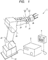
- FIG. 1 is a view schematically illustrating an overall structure of the robot apparatus 1 according to the first embodiment of the present invention.
- the robot apparatus 1 includes: a six-axis vertical multi-articulated robot (hereinafter, referred to as "multi-articulated robot") 2 that performs assembling of workpieces; a controller 3 that controls the multi-articulated robot 2; and a teaching pendant 4 that can be used to operate the multi-articulated robot 2.
- multi-articulated robot six-axis vertical multi-articulated robot
- the multi-articulated robot (multi-articulated manipulator) 2 includes a six-axis multi-articulated robot arm 20 and an end effector 21 connected to the distal end of the robot arm 20.
- the robot arm 20 includes six rotational joints (J1 to J6) and six actuators (in the present embodiment, servos) that are rotationally driven about joint axes (a J1 axis to a J6 axis), respectively.
- the robot arm 20 selectively drives the respective servos of the joints, to thereby move the end effector 21 to a desired three-dimensional position.
- the end effector 21 is detachably attached to the distal end of the robot arm 20, and is replaceable based on the contents of work.
- the end effector used in the present embodiment is a so-called hand, which is capable of griping a workpiece with three fingers.
- the controller (controlling apparatus) 3 includes: a servo controlling apparatus (see FIG. 5 to be described later) 30 that drive-controls the respective servos of the joints of the robot arm 20; and a joint controlling apparatus (see FIG. 5 to be described later) 31 that controls the joints of the robot arm 20.
- the controller 3 includes an end effector controlling apparatus that controls the end effector 21, a storage unit, a recording medium reading apparatus, and a communication apparatus.
- the joint controlling apparatus 31 controls each rotational joint such that the robot arm 20 moves while avoiding a quick movement at a particular rotational joint when the robot arm 20 approaches a singular point. Note that the joint controlling apparatus 31 is described later in detail.
- the servo controlling apparatus (joint drive controlling unit) 30 rotationally drives the respective servos of the rotational joints based on joint angle commands (to be described later) calculated by the joint controlling apparatus 31, to thereby move the robot arm 20.
- the storage unit stores therein a program (robot controlling program) for executing a robot controlling method (to be described later) and data such as singular points of the robot arm 20 and initial teaching points set in advance by a user.
- the recording medium reading apparatus is used to: read the contents of a computer-readable recording medium that records therein various programs such as the robot controlling program; and store the programs and the data recorded in the recording medium, into the storage unit.
- the communication apparatus is used to, for example, download an update program distributed via the Internet through the communication apparatus, without using the above-mentioned recording medium.
- the teaching pendant (operation unit) 4 is a human-machine interface for the user, and is used by the user to operate the multi-articulated robot 2. Moreover, the teaching pendant 4 has a function called jog operation. In the jog operation, for example, the hand tip position of the multi-articulated robot 2 can be linearly moved in three-dimensional coordinates while the user presses a button. Hence, the multi-articulated robot 2 may approach a singular point during the jog operation, and, if the multi-articulated robot 2 approaches the singular point, a particular joint may move quickly. In the present embodiment, even in the case where the multi-articulated robot 2 approaches the singular point, the joint controlling apparatus 31 enables the robot arm 20 to be driven while the quick movement at the particular joint is avoided.
- FIG. 2 is an explanatory view for describing a first singular point of the robot arm 20 according to the first embodiment.
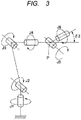
- FIG. 3 is an explanatory view for describing a second singular point of the robot arm 20 according to the first embodiment.
- FIG. 4 is an explanatory view for describing a third singular point of the robot arm 20 according to the first embodiment.
- a multi-articulated robot (multi-articulated manipulator) has a large number of singular points at which the joint angle cannot be calculated for a particular hand tip position.
- the six-axis multi-articulated robot 2 has three singular points (the first singular point to the third singular point), and the multi-articulated robot 2 may approach the three singular points at the same time.
- the three singular points of the multi-articulated robot 2 are described.
- the J1 axis direction is referred to as vertical direction
- the direction orthogonal to the J1 axis direction is referred to as horizontal direction
- a general industrial robot is designed such that the J1 axis direction is orthogonal to the J2 axis direction and that the J2 axis direction is parallel to the J3 axis direction, and hence description is given based on this condition.
- a configuration in which the J2 axis is offset in the horizontal direction with respect to the J1 axis can also be adopted, but can be discussed in a similar manner, and hence description thereof is omitted here.
- the J4 axis, the J5 axis and the J6 axis are designed in many cases so as to intersect with one another at one point (a point P illustrated in FIG. 2 to FIG. 4 ) in order to facilitate inverse kinematics calculation, and hence description is given based on this condition.
- the first singular point corresponds to the case where the point at which the J4 axis, the J5 axis and the J6 axis intersect with one another, that is, the point P is located on the J1 axis.
- the J1 axis, the J4 axis, the J5 axis and the J6 axis intersect with one another at one point (point P), and hence the rotation angles of the four rotational joints J1 and J4 to J6 are not determined.
- the rotation angle is determined by three types of directions (variables) in a three-dimensional space, whereas the number of variables is four, which is larger by one than three, at the first singular point. In the vicinity of the first singular point, a slight change in the position and the posture of the hand tip leads to significant changes in angles of the rotational joints J1 and J4 to J6.
- the rotation angle ⁇ 1 is a representative index showing the distance to the first singular point.
- the rotation angle (hereinafter, referred to as "singular point angle") of a particular rotational joint is used as a singular point distance.
- the rotation angle (singular point angle) ⁇ 1 of the rotational joint J2 falls below 15 degrees, a slight change in the position and the posture of the hand tip significantly changes the rotation angles of the rotational joints J1 and J4 to J6, which requires attention.
- the second singular point corresponds to the case where the J4 axis and the J6 axis are located on the same axis.
- the J4 axis and the J6 axis coincide with each other, and hence the rotation angles of the rotational joints J4 and J6 cannot be determined as one.
- a slight change in the position and the posture of the hand tip leads to significant changes in angles of the rotational joints J4 and J6.
- the third singular point corresponds to the case where the J2 axis and the J3 axis are located on the J4 axis.
- the rotation angles of the rotational joints J2 and J3 cannot be determined.
- a slight change in the position and the posture of the hand tip leads to significant changes in angles of the rotational joints J2 and J3.
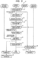
- FIG. 5 is a block diagram illustrating a configuration of the joint controlling apparatus 31 according to the first embodiment.
- the joint controlling apparatus 31 includes: a joint angle computing unit 32 that computes a joint angle command of each rotational joint for driving the robot arm 20 based on a motion command; and a singular point calculating unit 51 that calculates the singular point angle of each rotational joint to each singular point.
- the joint controlling apparatus 31 further includes a maximum joint angle deviation adjusting unit 52 that performs a process of making smaller a limit value of a maximum joint angle deviation (maximum rotation speed) given in advance for each rotational joint, according to the singular point angle.
- the joint angle computing unit 32 includes a position command calculating unit 50, a correction level adjusting unit 53, a position command correcting unit 54, an inverse kinematics calculating unit 55, a joint angle correcting unit 56, a forward kinematics calculating unit 57, and a correction amount calculating unit 58.
- the position command calculating unit 50 adds a deviation command of the hand tip of the robot arm 20 to a current position of the hand tip thereof expressed by three-dimensional coordinates, to thereby calculate a position command.
- the correction level adjusting unit 53 performs a process of calculating a correction level (which is a rate of correction and is hereinafter referred to as "correction rate") according to the degree of the singular point angle. Specifically, the correction level adjusting unit 53 performs a process of making the correction rate smaller as the singular point angle is smaller.
- the position command correcting unit 54 adds the product of a previous correction amount and the correction rate to the position command calculated by the position command calculating unit 50, to thereby calculate a corrected position command.
- the inverse kinematics calculating unit 55 transforms the position command corrected by the position command correcting unit 54 into a tentative joint angle command.
- the joint angle correcting unit 56 calculates a joint angle deviation from the tentative joint angle command calculated by the inverse kinematics calculating unit 55 and a previous joint angle command, and makes the tentative joint angle command smaller such that the joint angle deviation does not exceed the maximum joint angle deviation calculated by the maximum joint angle deviation adjusting unit 52, to thereby calculate a next joint angle command.
- the forward kinematics calculating unit 57 calculates a next joint angle command and a next position from the modified joint angle command.
- the correction amount calculating unit 58 adds a correction amount to the difference between the next position calculated by the forward kinematics calculating unit 57 and the position command, to thereby calculate a next correction amount.
- the maximum joint angle deviation adjusting unit (joint speed limiting unit) 52 makes the limit value of the maximum joint angle deviation (maximum rotation speed) smaller than the limit value of a preset maximum joint angle deviation, if the singular point angle of a rotational joint specified in advance based on the singular point type becomes smaller than a predetermined value.
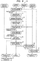
- FIG. 6 is an explanatory view for describing a function for calculating the maximum joint angle deviation.
- FIG. 7 is an explanatory view for describing joint axis to be subjected to speed limitation according to each singular point type.
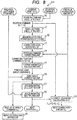
- a deviation command V i , a current position C i , a previous correction amount E i and a previous joint angle command q i are input from the teaching pendant 4 to the joint controlling apparatus 31, based on the input motion command. Consequently, the joint controlling apparatus 31 calculates a next joint angle command q i+1 , a next position C i+1 and a next correction amount E i+1 based on the input data, and outputs the calculation results to the servo controlling apparatus 30.
- the servo controlling apparatus 30 rotationally drives the rotational joints based on the input data, to thereby move the robot arm 20.
- a method of calculating the next joint angle commands q i+1 , the next position C i+1 and the next correction amount E i+1 by the joint controlling apparatus 31 is specifically described.
- the joint controlling apparatus 31 adds the deviation command V i of the hand tip and the current position C i of the hand tip, to thereby calculate a position command D i (position command calculating step).
- current position data and deviation command data are vectors having six components made of movements and rotations in the X, Y, and Z directions, and represent a position and a posture.
- Another method of representing such a position and a posture involves using a 4 ⁇ 4 homogeneous coordinate transformation matrix. In this method, the sum of the vectors is expressed by matrix multiplication. This is different in only how to express the position and the posture, and is irrelevant to the gist of the present invention. Hence, in the present embodiment, vector expression that is easy to understand intuitively is used to express the position and the posture.
- the joint controlling apparatus 31 calculates a singular point angle, and determines whether or not the robot arm 20 is in the vicinity of a singular point (singular point calculating step).
- the joint controlling apparatus 31 calculates the singular point angle of a corresponding rotational joint according to the three types of singular points. Note that the current joint angle can be used as a substitute for the singular point angle of the corresponding rotational joint. This is because the control cycle of the multi-articulated robot 2 according to the present embodiment is 2 ms, which is a sufficiently short time, and a change in joint angle is also small.
- the joint controlling apparatus 31 After the calculation of the singular point angle, the joint controlling apparatus 31 then performs the process of making smaller the limit value of the maximum joint angle deviation (maximum rotation speed) given in advance for each rotational joint, according to the singular point angle (joint speed adjusting step).
- the maximum rotation speed that is, the limit value of the maximum joint angle deviation is determined for each rotational joint, based on restrictions of torque generated by a motor and the maximum rotation speed that can be dealt with by an encoder. In this case, the limit value thereof is made further smaller according to the singular point angle.
- V max a maximum rotation angle deviation (maximum rotation speed) given for each rotational joint
- V min a rotation angle deviation when the singular point angle is zero
- ⁇ s an angle for determining the vicinity of the singular point
- V lim V max ⁇ V min ⁇ 2 ⁇ ⁇ s 3 + 3 ⁇ ⁇ s 2 + V min ⁇ ⁇ ⁇ s
- V lim V max ⁇ > ⁇ s
- the angle ⁇ s for determining the vicinity of the singular point is set to, for example, 15 degrees
- the rotation speed of a particular rotational joint is limited.
- the process of making the limit value smaller is performed for each rotational joint specified in advance based on the singular point type. For example, as illustrated in FIG. 7 , in the case of the first singular point, the limit values of the maximum joint angle deviations (maximum rotation speeds) of the rotational joints J1, J4, J5 and J6 are made smaller. Note that the minimum value of each limit value at this time is set to zero.
- the limit values of the maximum joint angle deviations (maximum rotation speeds) of the rotational joints J4 and J6 are made smaller.
- the minimum value of each limit value at this time is set to zero.
- the limit values of the maximum joint angle deviations (maximum rotation speeds) of the rotational joints J2 and J3 are made smaller. Note that the minimum value of each limit value at this time is set to not zero but, for example, a low speed such as one degree per second. This is because, if this speed is set to zero, an escape from the third singular point is impossible.
- the robot arm 20 may approach the first singular point to the third singular point at the same time.
- the joint controlling apparatus 31 calculates the maximum joint angle deviations (maximum rotation speeds) of the rotational joints, and defines the smallest one as a limit value.
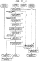
- the joint controlling apparatus 31 calculates a correction rate according to the singular point angle (correction level adjusting step).
- the singular point angle As described above, there are three singular points, and there are singular point angles corresponding to the three singular points.
- the minimum value of the singular point angles is regarded as the singular point angle.
- the correction rate is any number from 0 to 1.
- the correction rate is zero in the vicinity of the singular point, and is 1 at a position away from the singular point.
- a correction rate r can be represented by the following expression.
- the joint controlling apparatus 31 adds the product of the previous correction amount E i and the correction rate r to the position command D i calculated in the position command calculating step, to thereby calculate a corrected position command F i (position command correcting step).
- F i D i + rE i
- the correction rate becomes smaller in the vicinity of the singular point.
- the correction amount becomes smaller in the vicinity of the singular point.
- the correction amount becomes larger in the vicinity of the singular point, motions of the joints may become unstable.
- the correction amount becomes smaller in the vicinity of the singular point, and hence motions of the joints can be made stable.
- the joint controlling apparatus 31 transforms the position command F i corrected in the position command correcting step into a tentative joint angle command q ⁇ i
- the joint controlling apparatus 31 calculates a joint angle deviation from the tentative joint angle command q ⁇ i and the previous joint angle command q i , and makes the tentative joint angle command smaller such that the joint angle deviation does not exceed the maximum rotation angle deviation V lim calculated in the maximum joint angle deviation adjusting step, to thereby calculate the next joint angle command q i+1 (joint angle correcting step).
- the following expression needs to be established from such a condition that the joint angle deviation does not exceed the upper limit thereof.
- the joint controlling apparatus 31 calculates the next joint angle command q i+1 according to the following expression such that Expression 6 is satisfied.
- the joint controlling apparatus 31 calculates the next position C i+1 from the next joint angle command q i+1 (forward kinematics calculating step). Subsequently, the joint controlling apparatus 31 adds the correction amount E i to the difference between the next position C i+1 calculated in the forward kinematics calculating step and the position command D i+1 , to thereby calculate the next correction amount E i+1 (correction amount calculating step).
- E i + 1 D i + E i ⁇ C i + 1
- the robot apparatus 1 calculates the singular point angle (distance), adjusts the maximum joint angle deviation according to the singular point angle, and corrects the joint angle deviation such that the joint angle deviation is equal to or less than the maximum value thereof.
- the maximum joint angle deviation is set to be small in the vicinity of the singular point and is set to be large in the other areas, the problem that the motion of the multi-articulated robot becomes slower in the other areas than the singular point can be solved.
- the motion speed of the multi-articulated robot can be enhanced.
- the maximum joint angle deviation that is, the joint angle speed is limited for each rotational joint specified based on the singular point type, and hence a quick movement of the robot arm can be prevented.
- the position of the hand tip deviates from the original target position, so that the position of the hand tip needs to be corrected.
- the hand tip position is corrected even in the vicinity of the singular point, and hence a significant change in joint speed occurs.
- the singular point angle is calculated, the correction rate is adjusted accordingly, and the position command is corrected in consideration of the correction rate.
- the correction rate is set to be small in the vicinity of the singular point, and is set to be large in the other areas. As a result, the correction amount becomes smaller in the vicinity of the singular point, and hence the joint speed can be prevented from increasing.
- the multi-articulated robot 2 can be prevented from being stopped in order to avoid the joint speed from increasing, and hence the productivity can be enhanced. Moreover, if the robot arm 20 comes away from the singular point, the correction level becomes larger, and hence the position of the hand tip can follow the original target position.
- the robot apparatus 1 calculates the singular point angle for each singular point type, and thus can limit a different joint angle deviation, that is, the rotation speed of a different rotational joint for each singular point type. Hence, a prompt escape from the singular point is possible with the use of a rotational joint that is not decelerated even in the vicinity of the singular point.
- the robot apparatus 1 according to the first embodiment can make the correction amount smaller according to the smallest one of the singular point angles. Hence, calculation is stable even in the vicinity of the singular point, and the hand tip speed does not need to be decelerated, resulting in enhancement of the motion speed.
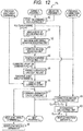
- FIG. 8 is a block diagram illustrating a configuration of a joint controlling apparatus 31A according to the second embodiment.
- the position and the posture is sequentially calculated from the joint at the root, whereby the position and the posture of the hand tip is calculated. Then, it is known that the position and the posture of the hand tip can be approximately calculated by multiplication using a Jacobian matrix.
- the Jacobian matrix calculating unit 59 calculates such a Jacobian matrix. In the case of the six-axis multi-articulated robot arm 20, the Jacobian matrix is a 6 ⁇ 6 matrix, and, if this matrix is multiplied by a deviation vector of the joint angle (joint speed), a deviation vector at the hand tip position (hand tip speed) is obtained.
- the Jacobian matrix multiplying unit 60 multiplies the Jacobian matrix by the difference between the joint angle command calculated in the joint angle correcting step and the previous joint angle command, that is, multiplies the Jacobian matrix by the deviation vector of the joint angle, and adds the current position to the obtained product, to thereby calculate the next position.
- the next position can be calculated according to the following expression.
- C i + 1 C i + J q i + 1 ⁇ q i
- the Jacobian matrix calculating unit 59 and the Jacobian matrix multiplying unit 60 are used as substitutes for the forward kinematics calculating unit 57, whereby the amount of calculation can be reduced.
- FIG. 9 is a block diagram illustrating a configuration of a joint controlling apparatus 31B according to the third embodiment.
- the speed of the robot arm 20 unexpectedly increases at the moment at which the robot arm 20 comes away from the vicinity of the singular point, and it is preferable not to accumulate the correction amount in the direction of a motion desired by an operator.
- the correction amount modifying unit 61 calculates the modified correction amount E i+1 from an unmodified correction amount ⁇ i + 1 and the directional vector v i .
- E i + 1 E ⁇ i + 1 ⁇ E ⁇ i + 1 ⁇ v i v i
- Expression 13 means that the directional component of the deviation command is removed from the correction amount.
- the correction amount can be made smaller, and hence an unnecessary increase in speed at the moment at which the robot arm 20 comes away from the vicinity of the singular point can be suppressed. Particularly from a standpoint of an operator of the teaching pendant, an increase in speed in a direction desired by the operator, that is, the direction of the deviation command can be suppressed.
- the correction amount becomes smaller, correction calculation in the vicinity of the singular point becomes more stable. Further, because the correction amount becomes smaller, the time required to return to an original target position can be shortened.
- FIG. 10 is a block diagram illustrating a configuration of a joint controlling apparatus 31C according to the fourth embodiment.
- the maximum joint angle deviation change adjusting unit 62 makes smaller a maximum joint angle deviation change (maximum rotation speed change) given in advance for each rotational joint, according to the singular point angle. Because the control cycle is constant, a joint angle deviation change is acceleration, and the maximum value thereof is determined for each rotational joint based on conditions of torque generable by the motor of each rotational joint and the like. Here, the limit value of the joint angle deviation change is made further smaller for deceleration, according to the singular point angle. A specific method for the deceleration is the same as the method that is described with reference to FIG. 6 in the case of the deviation (rotation speed).
- a decelerated maximum rotation angle deviation change A lim to the singular point angle ⁇ is calculated according to the following expression.
- the maximum joint angle deviation change is also limited in addition to the maximum joint angle deviation.
- the deviation change is calculated from the next joint angle command q i+1 , the previous joint angle command q i and a joint angle command q i-1 before the previous one according to the following expression. q i + 1 + q i ⁇ 1 ⁇ 2 q i
- the limitation of the maximum joint angle deviation is further put. This is the same as the joint angle correcting step in the first embodiment, and hence description thereof is omitted. Note that, with regard to the order of priority of the above-mentioned two types of limitations, in the fourth embodiment, the limitation of the maximum joint angle deviation is calculated after the limitation of the deviation change, and hence a higher priority is put on the limitation of the maximum joint angle deviation. According to the fourth embodiment, the maximum joint angle deviation change is also limited in addition to the maximum joint angle deviation, and hence smoother speed control is possible.
- FIG. 11 is a block diagram illustrating a configuration of a joint controlling apparatus 31D according to the fifth embodiment.
- the singular point angle can also be obtained through inverse kinematics calculation. Hence, if the singular point angle is calculated after this calculation, the singular point angle can be calculated using the latest joint angle.
- the corrected position command F i is calculated using a previous correction rate r i .
- F i D i + r i E i
- the fifth embodiment can produce effects similar to effects of the first embodiment.
- FIG. 12 is a block diagram illustrating a configuration of a joint controlling apparatus 31E according to the sixth embodiment.
- the correction rate is small in the vicinity of the singular point, and becomes larger as the robot arm 20 comes away from the singular point.
- the case where the robot arm 20 stays in the vicinity of the singular point for a long time and then comes away therefrom is discussed.
- correction is applied to the correction amount before such a long-time stay, and the robot arm 20 moves.
- movement of the robot arm 20 after the passage of a long time is not favorable to the operator.
- it is natural that the correction amount is attenuated with time.
- the attenuation calculating unit 63 performs attenuation calculation of the correction amount at a predetermined rate. Specifically, the attenuation calculating unit 63 substitutes nE i+1 into the modified correction amount E i+1 .
- the current position is described as C i calculated using the previous control cycle.
- the servo controlling apparatus may calculate an actual rotation angle, and may obtain the current position through forward kinematics calculation.
- Embodiments of the present invention can also be realized by a computer of a system or apparatus that reads out and executes computer executable instructions recorded on a storage medium (e.g., non-transitory computer-readable storage medium) to perform the functions of one or more of the above-described embodiment(s) of the present invention, and by a method performed by the computer of the system or apparatus by, for example, reading out and executing the computer executable instructions from the storage medium to perform the functions of one or more of the above-described embodiment(s).
- the computer may comprise one or more of a central processing unit (CPU), micro processing unit (MPU), or other circuitry, and may include a network of separate computers or separate computer processors.
- the computer executable instructions may be provided to the computer, for example, from a network or the storage medium.
- the storage medium may include, for example, one or more of a hard disk, a random-access memory (RAM), a read only memory (ROM), a storage of distributed computing systems, an optical disk (such as a compact disc (CD), digital versatile disc (DVD), or Blu-ray Disc (BD)TM), a flash memory device, a memory card, and the like.
Claims (14)
- Appareil robot (1), comprenant :un robot à articulations multiples (2) comprenant une pluralité d'articulations de rotation (J1 - J6) ;un effecteur d'extrémité (21) disposé sur le robot à articulations multiples (2) et mis en œuvre par les articulations de rotation (J1 - J6) ; etun appareil de commande (3) qui est configuré pour obtenir une instruction de position qui est une valeur d'instruction concernant une position de l'effecteur d'extrémité (21) sur la base d'une instruction de mouvement d'entrée, et pour piloter et commander le robot à articulations multiples (2), oùl'appareil de commande (3) comprend :une unité de calcul d'angle d'articulation (32) qui est configurée pour calculer une instruction d'angle d'articulation de chacune de la pluralité d'articulations de rotation (J1 - J6), l'instruction d'angle d'articulation ayant pour objet de piloter le robot à articulations multiples (2) sur la base de l'instruction de mouvement ;une unité de commande d'entraînement d'articulation (30) qui est configurée pour mouvoir le robot à articulations multiples (2) par un entraînement en rotation de chacune de la pluralité d'articulations de rotation (J1 - J6) sur la base de l'instruction d'angle d'articulation calculée par l'unité de calcul d'angle d'articulation (32) ;une unité de calcul de point singulier (51) qui est configurée pour calculer l'un d'un angle de point singulier et d'une distance de point singulier de chacune de la pluralité d'articulations de rotation (J1 - J6) par rapport à un point singulier du robot à articulations multiples (2) ; etune unité de limitation de vitesse d'articulation (52) qui est configurée pour limiter une vitesse de rotation d'une articulation de rotation (J1 - J6) spécifiée à l'avance sur la base d'un type du point singulier, si ledit un de l'angle de point singulier et de la distance de point singulier calculé par l'unité de calcul de point singulier (51) prend une valeur inférieure à une valeur prédéterminée, caractérisé en ce que l'unité de calcul d'angle d'articulation (32) comprend :
une unité de définition (53) qui est configurée pour définir un taux de correction de l'instruction de position sur la base de l'angle de point singulier ou de la distance de point singulier calculés par l'unité de calcul de point singulier (51). - Appareil robot (1) selon la revendication 1, dans lequel l'unité de limitation de vitesse d'articulation (52) est configurée pour amener une valeur de limite à une valeur de limite inférieure de façon à limiter la vitesse de rotation de l'articulation de rotation spécifiée (J1 - J6), conformément à l'un de l'angle de point singulier et de la distance de point singulier, si l'un de l'angle de point singulier et de la distance de point singulier prend une valeur inférieure à la valeur prédéterminée.
- Appareil robot (1) selon la revendication 1 ou 2, dans lequel l'unité de calcul d'angle d'articulation (32) comprend :une unité de calcul d'instruction de position (50) qui est configurée pour calculer une instruction de position sur la base de l'instruction de mouvement ;une unité de correction d'instruction de position (54) qui est configurée pour corriger l'instruction de position par une addition d'un produit d'une quantité de correction précédente et du taux de correction, calculé par l'unité de réglage de niveau de correction (53), à l'instruction de position ;une unité de calcul de cinématique inverse (55) qui est configurée pour transformer l'instruction de position corrigée par l'unité de correction d'instruction de position (54) en une instruction d'angle d'articulation de tentative ;une unité de correction d'angle d'articulation (56) qui est configurée pour calculer une instruction d'angle de rotation suivante par un calcul d'un écart d'angle d'articulation à partir de l'instruction d'angle d'articulation de tentative et d'une instruction d'angle d'articulation précédente, et amenant l'instruction d'angle d'articulation de tentative à prendre une valeur inférieure telle que l'écart d'angle d'articulation ne dépasse pas la vitesse de rotation ;une unité de calcul de prédiction de cinématique (57) qui est configurée pour calculer une position suivante à partir de l'instruction d'angle d'articulation suivante calculée par l'unité de correction d'angle d'articulation (56) ; etune unité de calcul de quantité de correction (58) qui est configurée pour calculer une quantité de correction suivante par une addition de la quantité de correction précédente à une différence entre la position suivante et l'instruction de position.
- Appareil robot (1) selon l'une quelconque des revendications 1 à 3, dans lequel
l'unité de définition (53) est configurée pour amener le taux de correction à un taux de correction inférieur à 1 dans un cas dans lequel l'angle de point singulier ou la distance de point singulier est inférieur ou égal à la valeur prédéterminée, et
l'unité de définition (53) est configurée pour définir le taux de correction à 1 dans un cas dans lequel l'angle de point singulier ou la distance de point singulier est supérieur à la valeur prédéterminée. - Procédé de commande de robot d'un appareil robot (1), dans lequel l'appareil robot (1) comprend un robot à articulations multiples (2) comprenant une pluralité d'articulations de rotation (J1 - J6) et un effecteur d'extrémité (21) disposé sur le robot à articulations multiples (2) et mis en œuvre par les articulations de rotation (J1 - J6), et le robot à articulations multiples (2) est commandé par pilotage par une obtention d'une instruction de position qui est une valeur d'instruction concernant une position de l'effecteur d'extrémité (21) sur la base d'une instruction de mouvement d'entrée, le procédé comprenant les étapes consistant à :calculer, par une unité de commande (3), une instruction d'angle d'articulation de chacune de la pluralité d'articulations de rotation, l'instruction d'angle d'articulation ayant pour objet de piloter le robot à articulations multiples (2) sur la base de l'instruction de mouvement ;mouvoir, par l'unité de commande (3), le robot articulations multiples (2) par un entraînement en rotation de chacune de la pluralité d'articulations de rotation (J1 - J6) sur la base de l'instruction d'angle d'articulation calculée à l'étape de calcul de l'instruction d'angle d'articulation ;calculer, par l'unité de commande (3), l'un d'un angle de point singulier et d'une distance de point singulier de chacune de la pluralité d'articulations de rotation (J1 - J6) par rapport à un point singulier du robot à articulations multiples (2) ; etlimiter, par l'unité de commande (3), une vitesse de rotation d'une articulation de rotation (J1 - J6) spécifiée à l'avance sur la base d'un type du point singulier, si ledit un de l'angle de point singulier et de la distance de point singulier calculés à l'étape de calcul dudit angle de point singulier et de ladite distance de point singulier prend une valeur inférieure à une valeur prédéterminée,le procédé étant caractérisé en ce qu'il comprend en outre l'étape consistant à :
définir, par l'unité de commande (3), un taux de correction de l'instruction de position sur la base de l'angle de point singulier ou de la distance de point singulier calculés à l'étape de calcul. - Procédé de commande robot selon la revendication 5, dans lequel
l'étape de limitation de la vitesse de rotation consiste à amener une valeur de limite à une valeur de limite inférieure de façon à limiter la vitesse de rotation de l'articulation de rotation spécifiée (J1 - J6), conformément à l'un de l'angle de point singulier et de la distance de point singulier, si l'un de l'angle de point singulier et de la distance de point singulier prend une valeur inférieure à la valeur prédéterminée. - Procédé de commande de robot selon la revendication 5 ou 6, dans lequel le calcul de l'instruction d'angle d'articulation comprend les étapes consistant à :calculer une instruction de position sur la base de l'instruction de mouvement ;corriger l'instruction de position par une addition d'un produit d'une quantité de correction précédente et du taux de correction, calculé à l'étape de calcul du taux de correction, à l'instruction de position ;exécuter un calcul de cinématique inverse par une transformation de l'instruction de position corrigée à l'étape de correction de l'instruction de position en une instruction d'angle d'articulation de tentative ;calculer une instruction d'angle d'articulation suivante par un calcul d'un écart d'angle d'articulation à partir de l'instruction d'angle d'articulation de tentative et d'une instruction d'angle d'articulation précédente, et amener l'instruction d'angle d'articulation de tentative à prendre une valeur inférieure de sorte que l'écart d'angle d'articulation ne dépasse pas la vitesse de rotation ;exécuter un calcul de prédiction de cinématique par un calcul d'une position suivante à partir de l'instruction d'angle d'articulation suivante calculée à l'étape de calcul de l'instruction d'angle d'articulation suivante ; etcalculer une quantité de correction suivante par une addition de la quantité de correction précédente à une différence entre la position suivante et l'instruction de position.
- Procédé de commande de robot selon la revendication 7, dans lequel l'exécution du calcul de prédiction de cinématique consiste à calculer la position suivante par : une obtention d'une matrice jacobienne ; une multiplication de la matrice jacobienne par une différence entre l'instruction d'angle d'articulation précédente et l'instruction d'angle d'articulation suivante calculée à l'étape de calcul de l'instruction d'angle d'articulation suivante ; et une addition d'une position courante à un produit obtenu.
- Procédé de commande de robot selon la revendication 7 ou 8, comprenant en outre l'étape consistant à :
éliminer une composante directionnelle d'une instruction d'écart d'un résultat de calcul de l'étape de calcul de la quantité de correction suivante. - Procédé de commande de robot selon l'une quelconque des revendications 7 à 9, dans lequel
l'étape de limitation de la vitesse de rotation consiste à calculer une variation de vitesse de rotation maximale en plus de la vitesse de rotation, et l'étape de calcul de l'instruction d'angle d'articulation suivante consiste à calculer l'instruction d'angle d'articulation suivante par : un calcul d'une variation d'écart d'angle d'articulation à partir de l'instruction d'angle d'articulation de tentative, de l'instruction d'angle d'articulation précédente et d'une instruction d'angle d'articulation précédant l'instruction d'angle d'articulation précédente ; le fait d'amener l'instruction d'angle d'articulation de tentative à une valeur inférieure de sorte que la variation d'écart d'angle de rotation ne dépasse pas une variation d'écart d'angle d'articulation maximal ; un calcul, en outre, de l'écart d'angle d'articulation à partir de l'instruction d'angle d'articulation de tentative et de l'instruction d'angle d'articulation précédente ; et le fait d'amener l'instruction d'angle d'articulation de tentative à prendre une valeur inférieure de sorte que l'écart d'angle d'articulation de dépasse pas un écart d'angle d'articulation maximal. - Procédé de commande de robot selon l'une quelconque des revendications 7 à 10, comprenant en outre l'étape consistant à :
exécuter un calcul d'atténuation d'un résultat de calcul de l'étape de calcul de la quantité de correction suivante selon un taux prédéterminé. - Procédé de commande de robot selon l'une quelconque des revendications 7 à 11, dans lequel, à l'étape de définition :le taux de correction est amené à prendre une valeur inférieure à 1 dans un cas dans lequel l'angle de point singulier ou la distance de point singulier est inférieur ou égal à la valeur prédéterminée, etle taux de correction est défini à 1 dans un cas dans lequel l'angle de point singulier ou la distance de point singulier est supérieur à la valeur prédéterminée.
- Produit-programme informatique comprenant des instructions qui, lorsque le produit-programme informatique est exécuté par un ordinateur, amènent l'ordinateur à commander l'appareil robot selon l'une quelconque des revendications 1 à 4 pour mettre en œuvre les étapes du procédé selon l'une quelconque des revendications 5 à 12.
- Support d'informations lisible par ordinateur contenant en mémoire le produit-programme informatique selon la revendication 13.
Applications Claiming Priority (1)
| Application Number | Priority Date | Filing Date | Title |
|---|---|---|---|
| JP2013162891A JP6238628B2 (ja) | 2013-08-06 | 2013-08-06 | ロボット装置、ロボット制御方法、ロボット制御プログラム及びロボット装置を用いた部品の製造方法 |
Publications (3)
| Publication Number | Publication Date |
|---|---|
| EP2835228A2 EP2835228A2 (fr) | 2015-02-11 |
| EP2835228A3 EP2835228A3 (fr) | 2015-04-15 |
| EP2835228B1 true EP2835228B1 (fr) | 2021-09-08 |
Family
ID=51225404
Family Applications (1)
| Application Number | Title | Priority Date | Filing Date |
|---|---|---|---|
| EP14178882.8A Active EP2835228B1 (fr) | 2013-08-06 | 2014-07-29 | Appareil robotique et procédé de commande de robot |
Country Status (4)
| Country | Link |
|---|---|
| US (1) | US9764462B2 (fr) |
| EP (1) | EP2835228B1 (fr) |
| JP (1) | JP6238628B2 (fr) |
| CN (1) | CN104339349B (fr) |
Families Citing this family (26)
| Publication number | Priority date | Publication date | Assignee | Title |
|---|---|---|---|---|
| JP6700669B2 (ja) | 2015-04-07 | 2020-05-27 | キヤノン株式会社 | 制御方法、ロボット装置、プログラム、記録媒体、及び物品の製造方法 |
| JP6657627B2 (ja) * | 2015-07-13 | 2020-03-04 | セイコーエプソン株式会社 | ロボット制御装置、ロボットおよびロボットシステム |
| CN105082134B (zh) * | 2015-08-06 | 2017-03-08 | 珞石(北京)科技有限公司 | 一种基于多判据的六自由度串联机器人奇异性处理方法 |
| JP7058929B2 (ja) | 2015-10-27 | 2022-04-25 | キヤノン株式会社 | 駆動装置、ロボット装置、制御方法、物品の製造方法、制御プログラム、および記録媒体 |
| CN105382835B (zh) * | 2015-12-11 | 2017-06-20 | 华中科技大学 | 一种可穿越腕部奇异点的机器人路径规划方法 |
| CN105437234B (zh) * | 2016-01-25 | 2017-09-22 | 珠海格力电器股份有限公司 | 一种多奇异点处理方法、系统和工业机器人 |
| CN106217345B (zh) * | 2016-08-31 | 2018-04-24 | 北京术锐技术有限公司 | 可实现姿态反馈的柔性连续体结构 |
| CN106426176B (zh) * | 2016-11-08 | 2018-06-26 | 北京邮电大学 | 一种六自由度空间机械臂动态负载能力工作空间分析方法 |
| US11192185B2 (en) | 2016-12-16 | 2021-12-07 | Canon Kabushiki Kaisha | Method of producing product |
| US11364630B2 (en) * | 2017-02-17 | 2022-06-21 | Abb Schweiz Ag | Method for controlling an industrial robot during lead-through programming of the robot and an industrial robot |
| JP6904759B2 (ja) * | 2017-04-11 | 2021-07-21 | 日本電産サンキョー株式会社 | ロボットの移動速度制御装置及び方法 |
| CN107451925A (zh) * | 2017-06-19 | 2017-12-08 | 中国烟草总公司广东省公司 | 农用智能系统及农用智能系统的控制方法 |
| CN107443372B (zh) * | 2017-07-06 | 2021-01-05 | 广州市轻工职业学校 | 一种面向机器人降级使用的运动规划方法 |
| JP6633587B2 (ja) * | 2017-10-05 | 2020-01-22 | ファナック株式会社 | ロボットの構成部材の速度を制限する制御装置 |
| US10919149B2 (en) * | 2017-11-24 | 2021-02-16 | Denso Wave Incorporated | Controller for robot and inverse transforming method for robot |
| TWI734106B (zh) * | 2018-04-27 | 2021-07-21 | 瑞士商愛爾康公司 | 立體視覺化攝影機及整合機器人平台 |
| US11045950B2 (en) | 2018-11-02 | 2021-06-29 | Canon Kabushiki Kaisha | Driving device and detecting device |
| US11667035B2 (en) * | 2019-07-01 | 2023-06-06 | Wisconsin Alumni Research Foundation | Path-modifying control system managing robot singularities |
| US20230116068A1 (en) * | 2020-03-11 | 2023-04-13 | Fanuc Corporation | Numerical controller |
| US11559893B2 (en) * | 2020-04-02 | 2023-01-24 | Intrinsic Innovation Llc | Robot control for avoiding singular configurations |
| CN111506100B (zh) * | 2020-06-15 | 2020-10-02 | 深圳市优必选科技股份有限公司 | 多足机器人关节控制方法、装置和多足机器人 |
| JP7171669B2 (ja) * | 2020-10-14 | 2022-11-15 | 川崎重工業株式会社 | 手術支援システム、患者側装置および手術支援システムの制御方法 |
| CN113085671B (zh) * | 2021-05-25 | 2022-08-26 | 中国铁建电气化局集团有限公司 | 一种隧道接触网吊柱安装多关节机器人 |
| CN114227685B (zh) * | 2021-12-28 | 2023-09-22 | 深圳市优必选科技股份有限公司 | 机械臂控制方法、装置、计算机可读存储介质及机械臂 |
| CN114310063B (zh) * | 2022-01-28 | 2023-06-06 | 长春职业技术学院 | 一种基于六轴机器人的焊接优化方法 |
| WO2023162225A1 (fr) * | 2022-02-28 | 2023-08-31 | ファナック株式会社 | Dispositif de commande de robot et robot à articulations multiples |
Family Cites Families (25)
| Publication number | Priority date | Publication date | Assignee | Title |
|---|---|---|---|---|
| JPH0630008B2 (ja) | 1985-09-09 | 1994-04-20 | 株式会社日立製作所 | ロボツトの制御方法 |
| US4716350A (en) * | 1986-12-08 | 1987-12-29 | Ford Motor Company | Method to avoid singularity in a robot mechanism |
| JP2607515B2 (ja) * | 1987-05-08 | 1997-05-07 | 三菱重工業株式会社 | 多関節型ロボットの軌跡制御装置 |
| JPH05324044A (ja) * | 1992-05-22 | 1993-12-07 | Fujitsu Ltd | ロボットの軌跡制御方式 |
| US5499320A (en) * | 1993-03-24 | 1996-03-12 | The United States Of America As Represented By The Administrator Of The National Aeronautics And Space Administration | Extended task space control for robotic manipulators |
| JPH11239988A (ja) * | 1998-02-24 | 1999-09-07 | Sumitomo Heavy Ind Ltd | 多関節ロボットのダイレクトティーチングにおける特異点回避方法 |
| US8004229B2 (en) * | 2005-05-19 | 2011-08-23 | Intuitive Surgical Operations, Inc. | Software center and highly configurable robotic systems for surgery and other uses |
| JP4049956B2 (ja) | 1999-10-01 | 2008-02-20 | 三菱電機株式会社 | ロボット制御装置 |
| US6845295B2 (en) * | 2002-03-07 | 2005-01-18 | Fanuc Robotics America, Inc. | Method of controlling a robot through a singularity |
| JP3896024B2 (ja) * | 2002-04-09 | 2007-03-22 | 新日本製鐵株式会社 | 垂直多関節型マニピュレータの制御装置 |
| JP3886842B2 (ja) | 2002-04-25 | 2007-02-28 | 三菱電機株式会社 | ロボットの制御装置 |
| DE10351670A1 (de) * | 2003-11-05 | 2005-06-30 | Kuka Roboter Gmbh | Verfahren und Vorrichtung zum Steuern von Robotern |
| JP4810251B2 (ja) | 2006-02-16 | 2011-11-09 | キヤノン株式会社 | 原子間力顕微鏡 |
| US7915787B2 (en) | 2007-07-20 | 2011-03-29 | Canon Kabushiki Kaisha | Actuator |
| JP2009032189A (ja) * | 2007-07-30 | 2009-02-12 | Toyota Motor Corp | ロボットの動作経路生成装置 |
| CN101549495B (zh) | 2008-03-31 | 2011-04-13 | 上海宝信软件股份有限公司 | 可避免奇异点发生的机器人控制方法 |
| JP5424581B2 (ja) | 2008-06-06 | 2014-02-26 | キヤノン株式会社 | 部分測定を合成する形状測定方法 |
| JP2010076058A (ja) * | 2008-09-26 | 2010-04-08 | Toshiba Corp | 多関節型マニピュレータの制御装置及び多関節型マニピュレータの手先動作軌道生成方法 |
| JP5231935B2 (ja) * | 2008-10-21 | 2013-07-10 | 株式会社東芝 | ロボット制御装置 |
| JP5283541B2 (ja) * | 2009-03-05 | 2013-09-04 | 株式会社神戸製鋼所 | ロボットの動作経路生成方法 |
| CN102510793B (zh) * | 2010-06-04 | 2015-01-28 | 中国科学院自动化研究所 | 加速度连续的机器人轨迹生成系统和方法 |
| JP5743495B2 (ja) | 2010-11-05 | 2015-07-01 | キヤノン株式会社 | ロボット制御装置 |
| JP5306313B2 (ja) * | 2010-12-20 | 2013-10-02 | 株式会社東芝 | ロボット制御装置 |
| CN102495550B (zh) | 2011-11-21 | 2013-07-10 | 湖南湖大艾盛汽车技术开发有限公司 | 并联机器人的正、逆动力学响应分析与控制方法 |
| CN102785248B (zh) | 2012-07-23 | 2015-03-04 | 华中科技大学 | 一种解耦型六自由度工业机器人的运动控制方法 |
-
2013
- 2013-08-06 JP JP2013162891A patent/JP6238628B2/ja active Active
-
2014
- 2014-07-18 US US14/335,761 patent/US9764462B2/en active Active
- 2014-07-29 EP EP14178882.8A patent/EP2835228B1/fr active Active
- 2014-08-04 CN CN201410379795.1A patent/CN104339349B/zh active Active
Also Published As
| Publication number | Publication date |
|---|---|
| US20150045954A1 (en) | 2015-02-12 |
| JP2015030078A (ja) | 2015-02-16 |
| US9764462B2 (en) | 2017-09-19 |
| CN104339349B (zh) | 2016-11-16 |
| EP2835228A3 (fr) | 2015-04-15 |
| CN104339349A (zh) | 2015-02-11 |
| EP2835228A2 (fr) | 2015-02-11 |
| JP6238628B2 (ja) | 2017-11-29 |
Similar Documents
| Publication | Publication Date | Title |
|---|---|---|
| EP2835228B1 (fr) | Appareil robotique et procédé de commande de robot | |
| US7912584B2 (en) | Power consumption estimation apparatus | |
| JP6717768B2 (ja) | 生産ラインにおける運用を考慮した学習制御を行うロボット及びその制御方法 | |
| KR100765671B1 (ko) | 로봇 궤적 제어 방법 및 장치와 로봇 궤적 제어 방법의프로그램을 기록한 컴퓨터 판독 가능한 기록 매체 | |
| JP5480198B2 (ja) | 学習制御機能を備えたスポット溶接ロボット | |
| JP5916583B2 (ja) | 多関節ロボットのウィービング制御装置 | |
| JP6006277B2 (ja) | 産業用ロボットのプログラム修正装置及びプログラム修正方法 | |
| JP2006215807A (ja) | ロボット制御装置および制御方法 | |
| JP2012135835A (ja) | ロボットの制御装置及びロボットの姿勢補間方法 | |
| JP2016055404A (ja) | 軌道生成方法、軌道生成装置、ロボット装置、プログラム及び記録媒体 | |
| JP2014208400A (ja) | ロボットの制御装置及びロボットの姿勢補間方法 | |
| JP2007000954A (ja) | ロボット教示装置及び方法 | |
| JP2020015124A (ja) | ロボット制御方法、物品の製造方法、ロボット制御装置、ロボット、プログラム及び記録媒体 | |
| US20200130187A1 (en) | Robot control method | |
| JP6429977B2 (ja) | ロボット装置及びロボット制御方法 | |
| JP2005118995A (ja) | ロボットの制御方法および制御装置 | |
| CN111405966A (zh) | 用于控制机器人组的方法和控制装置 | |
| JP4222338B2 (ja) | 適応型ビジュアルフィードバック制御方法 | |
| JP7227018B2 (ja) | 学習制御装置、ロボット制御装置およびロボット | |
| JP4528577B2 (ja) | 工業用ロボット | |
| EP3912767A1 (fr) | Dispositif de commande de robot, procédé de commande de robot et programme de commande de robot | |
| JP7378640B2 (ja) | ロボット制御装置およびロボット制御方法 | |
| JP7384933B2 (ja) | 制御システム | |
| JP2005230952A (ja) | 制御方法および制御装置 | |
| JPH02310706A (ja) | 多関節ロボット制御装置 |
Legal Events
| Date | Code | Title | Description |
|---|---|---|---|
| PUAI | Public reference made under article 153(3) epc to a published international application that has entered the european phase |
Free format text: ORIGINAL CODE: 0009012 |
|
| 17P | Request for examination filed |
Effective date: 20140729 |
|
| AK | Designated contracting states |
Kind code of ref document: A2 Designated state(s): AL AT BE BG CH CY CZ DE DK EE ES FI FR GB GR HR HU IE IS IT LI LT LU LV MC MK MT NL NO PL PT RO RS SE SI SK SM TR |
|
| AX | Request for extension of the european patent |
Extension state: BA ME |
|
| PUAL | Search report despatched |
Free format text: ORIGINAL CODE: 0009013 |
|
| AK | Designated contracting states |
Kind code of ref document: A3 Designated state(s): AL AT BE BG CH CY CZ DE DK EE ES FI FR GB GR HR HU IE IS IT LI LT LU LV MC MK MT NL NO PL PT RO RS SE SI SK SM TR |
|
| AX | Request for extension of the european patent |
Extension state: BA ME |
|
| RIC1 | Information provided on ipc code assigned before grant |
Ipc: B25J 9/16 20060101AFI20150306BHEP |
|
| R17P | Request for examination filed (corrected) |
Effective date: 20151015 |
|
| RBV | Designated contracting states (corrected) |
Designated state(s): AL AT BE BG CH CY CZ DE DK EE ES FI FR GB GR HR HU IE IS IT LI LT LU LV MC MK MT NL NO PL PT RO RS SE SI SK SM TR |
|
| STAA | Information on the status of an ep patent application or granted ep patent |
Free format text: STATUS: EXAMINATION IS IN PROGRESS |
|
| 17Q | First examination report despatched |
Effective date: 20191022 |
|
| STAA | Information on the status of an ep patent application or granted ep patent |
Free format text: STATUS: EXAMINATION IS IN PROGRESS |
|
| GRAP | Despatch of communication of intention to grant a patent |
Free format text: ORIGINAL CODE: EPIDOSNIGR1 |
|
| STAA | Information on the status of an ep patent application or granted ep patent |
Free format text: STATUS: GRANT OF PATENT IS INTENDED |
|
| INTG | Intention to grant announced |
Effective date: 20210317 |
|
| GRAS | Grant fee paid |
Free format text: ORIGINAL CODE: EPIDOSNIGR3 |
|
| GRAA | (expected) grant |
Free format text: ORIGINAL CODE: 0009210 |
|
| STAA | Information on the status of an ep patent application or granted ep patent |
Free format text: STATUS: THE PATENT HAS BEEN GRANTED |
|
| AK | Designated contracting states |
Kind code of ref document: B1 Designated state(s): AL AT BE BG CH CY CZ DE DK EE ES FI FR GB GR HR HU IE IS IT LI LT LU LV MC MK MT NL NO PL PT RO RS SE SI SK SM TR |
|
| REG | Reference to a national code |
Ref country code: GB Ref legal event code: FG4D |
|
| REG | Reference to a national code |
Ref country code: AT Ref legal event code: REF Ref document number: 1428163 Country of ref document: AT Kind code of ref document: T Effective date: 20210915 Ref country code: CH Ref legal event code: EP |
|
| REG | Reference to a national code |
Ref country code: IE Ref legal event code: FG4D |
|
| REG | Reference to a national code |
Ref country code: DE Ref legal event code: R096 Ref document number: 602014079958 Country of ref document: DE |
|
| REG | Reference to a national code |
Ref country code: LT Ref legal event code: MG9D |
|
| REG | Reference to a national code |
Ref country code: NL Ref legal event code: MP Effective date: 20210908 |
|
| PG25 | Lapsed in a contracting state [announced via postgrant information from national office to epo] |
Ref country code: HR Free format text: LAPSE BECAUSE OF FAILURE TO SUBMIT A TRANSLATION OF THE DESCRIPTION OR TO PAY THE FEE WITHIN THE PRESCRIBED TIME-LIMIT Effective date: 20210908 Ref country code: RS Free format text: LAPSE BECAUSE OF FAILURE TO SUBMIT A TRANSLATION OF THE DESCRIPTION OR TO PAY THE FEE WITHIN THE PRESCRIBED TIME-LIMIT Effective date: 20210908 Ref country code: SE Free format text: LAPSE BECAUSE OF FAILURE TO SUBMIT A TRANSLATION OF THE DESCRIPTION OR TO PAY THE FEE WITHIN THE PRESCRIBED TIME-LIMIT Effective date: 20210908 Ref country code: LT Free format text: LAPSE BECAUSE OF FAILURE TO SUBMIT A TRANSLATION OF THE DESCRIPTION OR TO PAY THE FEE WITHIN THE PRESCRIBED TIME-LIMIT Effective date: 20210908 Ref country code: BG Free format text: LAPSE BECAUSE OF FAILURE TO SUBMIT A TRANSLATION OF THE DESCRIPTION OR TO PAY THE FEE WITHIN THE PRESCRIBED TIME-LIMIT Effective date: 20211208 Ref country code: NO Free format text: LAPSE BECAUSE OF FAILURE TO SUBMIT A TRANSLATION OF THE DESCRIPTION OR TO PAY THE FEE WITHIN THE PRESCRIBED TIME-LIMIT Effective date: 20211208 Ref country code: FI Free format text: LAPSE BECAUSE OF FAILURE TO SUBMIT A TRANSLATION OF THE DESCRIPTION OR TO PAY THE FEE WITHIN THE PRESCRIBED TIME-LIMIT Effective date: 20210908 Ref country code: ES Free format text: LAPSE BECAUSE OF FAILURE TO SUBMIT A TRANSLATION OF THE DESCRIPTION OR TO PAY THE FEE WITHIN THE PRESCRIBED TIME-LIMIT Effective date: 20210908 |
|
| REG | Reference to a national code |
Ref country code: AT Ref legal event code: MK05 Ref document number: 1428163 Country of ref document: AT Kind code of ref document: T Effective date: 20210908 |
|
| PG25 | Lapsed in a contracting state [announced via postgrant information from national office to epo] |
Ref country code: LV Free format text: LAPSE BECAUSE OF FAILURE TO SUBMIT A TRANSLATION OF THE DESCRIPTION OR TO PAY THE FEE WITHIN THE PRESCRIBED TIME-LIMIT Effective date: 20210908 Ref country code: GR Free format text: LAPSE BECAUSE OF FAILURE TO SUBMIT A TRANSLATION OF THE DESCRIPTION OR TO PAY THE FEE WITHIN THE PRESCRIBED TIME-LIMIT Effective date: 20211209 |
|
| PG25 | Lapsed in a contracting state [announced via postgrant information from national office to epo] |
Ref country code: AT Free format text: LAPSE BECAUSE OF FAILURE TO SUBMIT A TRANSLATION OF THE DESCRIPTION OR TO PAY THE FEE WITHIN THE PRESCRIBED TIME-LIMIT Effective date: 20210908 |
|
| PG25 | Lapsed in a contracting state [announced via postgrant information from national office to epo] |
Ref country code: IS Free format text: LAPSE BECAUSE OF FAILURE TO SUBMIT A TRANSLATION OF THE DESCRIPTION OR TO PAY THE FEE WITHIN THE PRESCRIBED TIME-LIMIT Effective date: 20220108 Ref country code: SM Free format text: LAPSE BECAUSE OF FAILURE TO SUBMIT A TRANSLATION OF THE DESCRIPTION OR TO PAY THE FEE WITHIN THE PRESCRIBED TIME-LIMIT Effective date: 20210908 Ref country code: SK Free format text: LAPSE BECAUSE OF FAILURE TO SUBMIT A TRANSLATION OF THE DESCRIPTION OR TO PAY THE FEE WITHIN THE PRESCRIBED TIME-LIMIT Effective date: 20210908 Ref country code: RO Free format text: LAPSE BECAUSE OF FAILURE TO SUBMIT A TRANSLATION OF THE DESCRIPTION OR TO PAY THE FEE WITHIN THE PRESCRIBED TIME-LIMIT Effective date: 20210908 Ref country code: PT Free format text: LAPSE BECAUSE OF FAILURE TO SUBMIT A TRANSLATION OF THE DESCRIPTION OR TO PAY THE FEE WITHIN THE PRESCRIBED TIME-LIMIT Effective date: 20220110 Ref country code: PL Free format text: LAPSE BECAUSE OF FAILURE TO SUBMIT A TRANSLATION OF THE DESCRIPTION OR TO PAY THE FEE WITHIN THE PRESCRIBED TIME-LIMIT Effective date: 20210908 Ref country code: NL Free format text: LAPSE BECAUSE OF FAILURE TO SUBMIT A TRANSLATION OF THE DESCRIPTION OR TO PAY THE FEE WITHIN THE PRESCRIBED TIME-LIMIT Effective date: 20210908 Ref country code: EE Free format text: LAPSE BECAUSE OF FAILURE TO SUBMIT A TRANSLATION OF THE DESCRIPTION OR TO PAY THE FEE WITHIN THE PRESCRIBED TIME-LIMIT Effective date: 20210908 Ref country code: CZ Free format text: LAPSE BECAUSE OF FAILURE TO SUBMIT A TRANSLATION OF THE DESCRIPTION OR TO PAY THE FEE WITHIN THE PRESCRIBED TIME-LIMIT Effective date: 20210908 Ref country code: AL Free format text: LAPSE BECAUSE OF FAILURE TO SUBMIT A TRANSLATION OF THE DESCRIPTION OR TO PAY THE FEE WITHIN THE PRESCRIBED TIME-LIMIT Effective date: 20210908 |
|
| REG | Reference to a national code |
Ref country code: DE Ref legal event code: R097 Ref document number: 602014079958 Country of ref document: DE |
|
| PLBE | No opposition filed within time limit |
Free format text: ORIGINAL CODE: 0009261 |
|
| STAA | Information on the status of an ep patent application or granted ep patent |
Free format text: STATUS: NO OPPOSITION FILED WITHIN TIME LIMIT |
|
| PG25 | Lapsed in a contracting state [announced via postgrant information from national office to epo] |
Ref country code: DK Free format text: LAPSE BECAUSE OF FAILURE TO SUBMIT A TRANSLATION OF THE DESCRIPTION OR TO PAY THE FEE WITHIN THE PRESCRIBED TIME-LIMIT Effective date: 20210908 |
|
| 26N | No opposition filed |
Effective date: 20220609 |
|
| PG25 | Lapsed in a contracting state [announced via postgrant information from national office to epo] |
Ref country code: SI Free format text: LAPSE BECAUSE OF FAILURE TO SUBMIT A TRANSLATION OF THE DESCRIPTION OR TO PAY THE FEE WITHIN THE PRESCRIBED TIME-LIMIT Effective date: 20210908 |
|
| PGFP | Annual fee paid to national office [announced via postgrant information from national office to epo] |
Ref country code: DE Payment date: 20220621 Year of fee payment: 9 |
|
| PG25 | Lapsed in a contracting state [announced via postgrant information from national office to epo] |
Ref country code: IT Free format text: LAPSE BECAUSE OF FAILURE TO SUBMIT A TRANSLATION OF THE DESCRIPTION OR TO PAY THE FEE WITHIN THE PRESCRIBED TIME-LIMIT Effective date: 20210908 |
|
| PG25 | Lapsed in a contracting state [announced via postgrant information from national office to epo] |
Ref country code: MC Free format text: LAPSE BECAUSE OF FAILURE TO SUBMIT A TRANSLATION OF THE DESCRIPTION OR TO PAY THE FEE WITHIN THE PRESCRIBED TIME-LIMIT Effective date: 20210908 |
|
| REG | Reference to a national code |
Ref country code: CH Ref legal event code: PL |
|
| GBPC | Gb: european patent ceased through non-payment of renewal fee |
Effective date: 20220729 |
|
| REG | Reference to a national code |
Ref country code: BE Ref legal event code: MM Effective date: 20220731 |
|
| PG25 | Lapsed in a contracting state [announced via postgrant information from national office to epo] |
Ref country code: LU Free format text: LAPSE BECAUSE OF NON-PAYMENT OF DUE FEES Effective date: 20220729 Ref country code: LI Free format text: LAPSE BECAUSE OF NON-PAYMENT OF DUE FEES Effective date: 20220731 Ref country code: FR Free format text: LAPSE BECAUSE OF NON-PAYMENT OF DUE FEES Effective date: 20220731 Ref country code: CH Free format text: LAPSE BECAUSE OF NON-PAYMENT OF DUE FEES Effective date: 20220731 |
|
| PG25 | Lapsed in a contracting state [announced via postgrant information from national office to epo] |
Ref country code: GB Free format text: LAPSE BECAUSE OF NON-PAYMENT OF DUE FEES Effective date: 20220729 Ref country code: BE Free format text: LAPSE BECAUSE OF NON-PAYMENT OF DUE FEES Effective date: 20220731 |
|
| PG25 | Lapsed in a contracting state [announced via postgrant information from national office to epo] |
Ref country code: IE Free format text: LAPSE BECAUSE OF NON-PAYMENT OF DUE FEES Effective date: 20220729 |
|
| REG | Reference to a national code |
Ref country code: DE Ref legal event code: R119 Ref document number: 602014079958 Country of ref document: DE |
|
| PG25 | Lapsed in a contracting state [announced via postgrant information from national office to epo] |
Ref country code: HU Free format text: LAPSE BECAUSE OF FAILURE TO SUBMIT A TRANSLATION OF THE DESCRIPTION OR TO PAY THE FEE WITHIN THE PRESCRIBED TIME-LIMIT; INVALID AB INITIO Effective date: 20140729 |
|
| PG25 | Lapsed in a contracting state [announced via postgrant information from national office to epo] |
Ref country code: MK Free format text: LAPSE BECAUSE OF FAILURE TO SUBMIT A TRANSLATION OF THE DESCRIPTION OR TO PAY THE FEE WITHIN THE PRESCRIBED TIME-LIMIT Effective date: 20210908 Ref country code: DE Free format text: LAPSE BECAUSE OF NON-PAYMENT OF DUE FEES Effective date: 20240201 Ref country code: CY Free format text: LAPSE BECAUSE OF FAILURE TO SUBMIT A TRANSLATION OF THE DESCRIPTION OR TO PAY THE FEE WITHIN THE PRESCRIBED TIME-LIMIT Effective date: 20210908 |