EP2829496B1 - Zonensteuerung und fördervorrichtung - Google Patents
Zonensteuerung und fördervorrichtung Download PDFInfo
- Publication number
- EP2829496B1 EP2829496B1 EP13764466.2A EP13764466A EP2829496B1 EP 2829496 B1 EP2829496 B1 EP 2829496B1 EP 13764466 A EP13764466 A EP 13764466A EP 2829496 B1 EP2829496 B1 EP 2829496B1
- Authority
- EP
- European Patent Office
- Prior art keywords
- signal
- zone controller
- zone
- controller system
- node number
- Prior art date
- Legal status (The legal status is an assumption and is not a legal conclusion. Google has not performed a legal analysis and makes no representation as to the accuracy of the status listed.)
- Active
Links
Images


Classifications
-
- B—PERFORMING OPERATIONS; TRANSPORTING
- B65—CONVEYING; PACKING; STORING; HANDLING THIN OR FILAMENTARY MATERIAL
- B65G—TRANSPORT OR STORAGE DEVICES, e.g. CONVEYORS FOR LOADING OR TIPPING, SHOP CONVEYOR SYSTEMS OR PNEUMATIC TUBE CONVEYORS
- B65G43/00—Control devices, e.g. for safety, warning or fault-correcting
- B65G43/10—Sequence control of conveyors operating in combination
-
- G—PHYSICS
- G05—CONTROLLING; REGULATING
- G05B—CONTROL OR REGULATING SYSTEMS IN GENERAL; FUNCTIONAL ELEMENTS OF SUCH SYSTEMS; MONITORING OR TESTING ARRANGEMENTS FOR SUCH SYSTEMS OR ELEMENTS
- G05B19/00—Program-control systems
- G05B19/02—Program-control systems electric
- G05B19/04—Program control other than numerical control, i.e. in sequence controllers or logic controllers
- G05B19/042—Program control other than numerical control, i.e. in sequence controllers or logic controllers using digital processors
-
- G—PHYSICS
- G05—CONTROLLING; REGULATING
- G05B—CONTROL OR REGULATING SYSTEMS IN GENERAL; FUNCTIONAL ELEMENTS OF SUCH SYSTEMS; MONITORING OR TESTING ARRANGEMENTS FOR SUCH SYSTEMS OR ELEMENTS
- G05B19/00—Program-control systems
- G05B19/02—Program-control systems electric
- G05B19/418—Total factory control, i.e. centrally controlling a plurality of machines, e.g. direct or distributed numerical control [DNC], flexible manufacturing systems [FMS], integrated manufacturing systems [IMS] or computer integrated manufacturing [CIM]
- G05B19/4185—Total factory control, i.e. centrally controlling a plurality of machines, e.g. direct or distributed numerical control [DNC], flexible manufacturing systems [FMS], integrated manufacturing systems [IMS] or computer integrated manufacturing [CIM] characterised by the network communication
-
- G—PHYSICS
- G05—CONTROLLING; REGULATING
- G05B—CONTROL OR REGULATING SYSTEMS IN GENERAL; FUNCTIONAL ELEMENTS OF SUCH SYSTEMS; MONITORING OR TESTING ARRANGEMENTS FOR SUCH SYSTEMS OR ELEMENTS
- G05B2219/00—Program-control systems
- G05B2219/20—Pc systems
- G05B2219/24—Pc safety
- G05B2219/24033—Failure, fault detection and isolation
-
- G—PHYSICS
- G05—CONTROLLING; REGULATING
- G05B—CONTROL OR REGULATING SYSTEMS IN GENERAL; FUNCTIONAL ELEMENTS OF SUCH SYSTEMS; MONITORING OR TESTING ARRANGEMENTS FOR SUCH SYSTEMS OR ELEMENTS
- G05B2219/00—Program-control systems
- G05B2219/30—Nc systems
- G05B2219/33—Director till display
- G05B2219/33145—Count clock pulses to determine address of node, module
-
- G—PHYSICS
- G05—CONTROLLING; REGULATING
- G05B—CONTROL OR REGULATING SYSTEMS IN GENERAL; FUNCTIONAL ELEMENTS OF SUCH SYSTEMS; MONITORING OR TESTING ARRANGEMENTS FOR SUCH SYSTEMS OR ELEMENTS
- G05B2219/00—Program-control systems
- G05B2219/30—Nc systems
- G05B2219/33—Director till display
- G05B2219/33226—Daisy chain
-
- G—PHYSICS
- G05—CONTROLLING; REGULATING
- G05B—CONTROL OR REGULATING SYSTEMS IN GENERAL; FUNCTIONAL ELEMENTS OF SUCH SYSTEMS; MONITORING OR TESTING ARRANGEMENTS FOR SUCH SYSTEMS OR ELEMENTS
- G05B2219/00—Program-control systems
- G05B2219/30—Nc systems
- G05B2219/45—Nc applications
- G05B2219/45054—Handling, conveyor
-
- Y—GENERAL TAGGING OF NEW TECHNOLOGICAL DEVELOPMENTS; GENERAL TAGGING OF CROSS-SECTIONAL TECHNOLOGIES SPANNING OVER SEVERAL SECTIONS OF THE IPC; TECHNICAL SUBJECTS COVERED BY FORMER USPC CROSS-REFERENCE ART COLLECTIONS [XRACs] AND DIGESTS
- Y02—TECHNOLOGIES OR APPLICATIONS FOR MITIGATION OR ADAPTATION AGAINST CLIMATE CHANGE
- Y02P—CLIMATE CHANGE MITIGATION TECHNOLOGIES IN THE PRODUCTION OR PROCESSING OF GOODS
- Y02P90/00—Enabling technologies with a potential contribution to greenhouse gas [GHG] emissions mitigation
- Y02P90/02—Total factory control, e.g. smart factories, flexible manufacturing systems [FMS] or integrated manufacturing systems [IMS]
Definitions
- the present invention relates to a conveyor device of a distributed control type and, more particularly, to a conveyor device which is capable of easily identifying an abnormal part when an abnormality such as a failure occurs, and easily performing communication with a host controller.
- the present invention also relates to a zone controller used for the distributed control type conveyor device.
- a conveyor device is used in a delivery center of a home delivery company or a post office.
- a conveyor device there are known a roller conveyor device in which cylindrical conveying rollers are arranged along a conveyance line, a belt conveyor device in which a conveying belt is mounted in a stretched state, and the like.
- a distributed control system (Patent Document 1).
- a plurality of zone conveyors are arranged in series to form a continuous conveying path.
- Each zone conveyor is provided with an independent motor.
- each zone conveyor is provided with a zone controller, and the zone controller manages/controls the corresponding zone conveyor.
- the zone controller outputs a motor drive signal and receives a signal from a load presence sensor provided in each zone.
- the zone controller is provided with a communication function and exchanges a signal with the adjacent zone controllers.
- information indicating an ON/OFF state of the load presence sensor or information indicating whether or not the motor is activated is exchanged between adjacent zone controllers.
- the zone controller activates the motor of the corresponding zone to convey the conveying object to the downstream side zone.
- the distributed control type conveyor device has an advantage that a layout can easily be changed. For example, when an overall length of the conveyor device is to be extended, a new zone conveyor is mounted to an end or middle portion of the existing conveyor device. On the other hand, when the overall length of the conveyor device is to be reduced, any of the zone conveyors may be removed, and a generated space may be eliminated.
- a distributed control type conveyor device has a drawback in that, when a failure or the like occurs, a failure part cannot easily be identified. Further, it is difficult to identify a defective part in a test run.
- the conveyor device is provided with a large number of motors and sensors, which increases a failure occurrence frequency. Further, while the motors or sensors need to be subjected to wiring one by one at installation of the conveyor device, erroneous wiring may occur.
- the defective part needs to be identified so as to repair or correct the failure.
- the distributed control type conveyor device does not originally have a central controller or, even if it has the central controller, the function thereof is restrictive. That is, even if there is the central controller, individual motors or sensors are not directly connected to the central controller, and thus the central controller cannot grasp which component in which zone has the defect.
- the present invention has been made in view of the above conventional problems, and an object thereof is to provide a zone controller and a conveyor device capable of easily indentifying a defective part such as a failure part.
- a zone controller which is used for a conveyor device in which a plurality of zone conveyors are arranged in series, which manages one or a plurality of the zone conveyors to control an operation thereof, and which is configured to receive a signal from a different zone controller and transmit a signal to an outside
- the zone controller including: a signal creation function that creates a predetermined abnormality alarm signal and transmits the created abnormality alarm signal to the outside when an abnormality occurs in a zone managed by the zone controller itself; a signal reception function that receives the abnormality alarm signal from the different zone controller; a signal processing function that applies certain processing to the received abnormality alarm signal; and a processed signal transmission function that transmits the signal processed by the signal processing function to the outside as the abnormality alarm signal.
- the zone controller according to the present aspect is used for a conveyor device in which a plurality of zone conveyors are arranged in series, and controls the conveyor device in a distributed manner.
- the zone controller can receive a signal from another zone controller and can transmit a signal to the outside, thereby allowing a signal exchange with adjacent zone controllers. For example, information indicating an ON/OFF state of the load presence sensor in the adjacent zones or information indicating whether or not the motor in the adjacent zones is activated is exchanged between adjacent zone controllers, thereby allowing a conveying object to be conveyed to the adjacent zone.
- the zone controller includes a signal creation function, and creates a predetermined abnormality alarm signal and transmits the created abnormality alarm signal to the outside when an abnormality occurs in a zone managed by the zone controller itself.
- the abnormality alarm signal is received by an adjacent zone controller.
- certain processing is applied to the received abnormality alarm signal.
- the adjacent zone controller transmits the signal processed using the signal processing function to the outside as the abnormality alarm signal. Further, a zone controller adjacently disposed to the adjacent zone controller receives the abnormality alarm signal after processing, and again applies processing to the processed abnormality alarm signal.
- the abnormality alarm signal transmitted from such a zone controller is a signal that has been processed twice.
- the abnormality alarm signal sequentially passes through the adjacent zone controllers while being subjected to processing. That is, reception, processing, and transmission of the abnormality alarm signal are performed in the zone controllers in a successive manner.
- the abnormality alarm signal reaches a specific (e.g., endmost) zone controller. Then, the abnormality alarm signal transmitted from this specific (e.g., endmost) zone controller is analyzed to examine a processed state, whereby a zone controller that has first created the abnormality alarm signal can be identified.
- a specific zone controller e.g., endmost
- the abnormality alarm signal transmitted from a zone controller of a zone in which an abnormality has actually occurred is a signal that has not been subjected to processing at all.
- the abnormality alarm signal transmitted from the adjacent zone controller is a signal that has been subjected to processing once.
- the abnormality alarm signal transmitted from the next adjacent zone controller is a signal that has been subjected to processing twice, and the abnormality alarm signal transmitted from the further adjacent zone controller is a signal that has been subjected to processing three times. That is, by going back along a signal transmission path by the number of times of processing, a zone controller of a zone in which an abnormality has actually occurred can be identified.
- the abnormality alarm signal created by the signal creation function is a pulse signal having a fixed time length, and the signal processing function increases or reduces a pulse width of the pulse signal.
- a zone controller of a zone in which an abnormality has actually occurred can be retrieved.
- the predetermined signal created by the signal creation function is a pulse signal having a fixed time length
- the signal processing function adds or subtracts a new pulse to or from the pulse signal to increase or reduce the number of pulses.
- a zone controller of a zone in which an abnormality has actually occurred can be retrieved.
- a zone controller which is used for a conveyor device in which a plurality of zone conveyors are arranged in series, which manages one or a plurality of the zone conveyors to control an operation thereof, and which is configured to receive a signal from a different zone controller and transmit a signal to an outside
- the zone controller including: a signal reception function that receives a pulse signal from the different zone controller; a signal processing function that applies certain processing to the received pulse signal based on a certain function; and a processed signal transmission function that transmits the signal processed by the signal processing function to the outside.
- the different zone controller it is possible to receive a pulse signal from the different zone controller, apply certain processing to the received pulse signal based on a certain function, and transmit the processed signal to the outside. This allows identification of a zone controller corresponding to a zone in which the abnormality has occurred.
- the zone controller transmits to the outside a signal added with information for identifying the zone controller itself.
- This facilitates exchange of a control signal between a device such as a central controller configured to transmit a control signal to each of the zone controllers constituting the conveyor device and a specific controller of the plurality of zone controllers. This facilitates control with respect to only the specific controller out of the plurality of zone controllers.
- the zone controller further includes a storage unit that stores the signal processed by the zone controller itself or information related to the processed signal.
- signal processing or arithmetic processing for the signal processing need not be performed for each signal transmission, thereby further facilitating exchange of the control signal.
- the zone controller further includes a signal creation function that creates a predetermined abnormality alarm signal and transmits the created abnormality alarm signal to the outside when an abnormality occurs in a zone managed by the zone controller itself, and the zone controller transmits the abnormality alarm signal and a signal based on the information stored in the storage unit.
- a zone controller corresponding to a zone in which an abnormality has occurred may be identified by transmitting the abnormality alarm signal and a signal based on information stored in the storage unit. In this case, it is possible to identify the zone controller without acquiring the number of times of signal processing through calculation or the like.
- the zone controller further includes a node number calculation function that determines a node number of the zone controller itself based on the received pulse signal, and information related to the node number created by the node number determination function is stored in the storage unit.
- the description "determines a node number of the zone controller itself based on the received pulse signal” herein includes both an operation of determining the node number of the zone controller itself based on the received pulse signal and an operation of determining the node number of the zone controller itself based on a signal created by applying certain processing to the received pulse signal by the signal processing function.
- the node number calculation function determines the node number of the zone controller itself based on a pulse width or the number of pulses of the received pulse signal.
- the zone controller further includes a signal creation function that creates a predetermined abnormality alarm signal and transmits the created abnormality alarm signal to the outside when an abnormality occurs in a zone managed by the zone controller itself.
- the storage unit is configured to store information related to the node number, and the processed signal transmission function outputs both a signal indicating the information related to the node number and the abnormality alarm signal.
- the zone controller is configured to output a pseudo abnormality alarm signal.
- a conveyor device in which a plurality of zone conveyors are arranged in series, in which the above-described zone controller is provided for each zone or for each set of a plurality of zones, and in which a signal is exchanged between the adjacent zone controllers, wherein when the zone controller receives the predetermined signal from a zone controller adjacently disposed on one side thereof by the signal reception function, the zone controller transmits a signal processed by the signal processing function, as an abnormality alarm signal, to a zone controller adjacently disposed on the other side thereof.
- a pseudo abnormality alarm signal is created and transmitted to the zone controller, the zone controllers that receive the pseudo abnormality signal perform, in a successive manner, a process of applying processing to the signal by the signal processing function and transmitting the processed signal to zone controllers adjacently disposed on the other side thereof by the processed signal transmission function, and each of the zone controllers is configured to store the signal processed by itself or information related to the processed signal.
- each of the zone controllers is allowed to store a position of the zone controller itself on a signal path.
- a pseudo abnormality alarm signal is created and transmitted to the zone controller, and the zone controllers that receive the pseudo abnormality signal perform, in a successive manner, a process of applying processing to the signal by the signal processing function and transmitting the processed signal to zone controllers adjacently disposed on the other side thereof by the processed signal transmission function. Then, the zone controllers receive or transmit the abnormality alarm signal different in the number of times of processing.
- the number of zone controllers interposed between each of the zone controllers and the zone controller that first receives or transmits the pseudo signal is identified and, thus, the position of the each zone controller is indirectly stored. Therefore, in the conveyor device of the present invention, a relative position of each zone controller is stored therein.
- a conveyor device in which a plurality of zone conveyors are arranged in series, in which the above-described zone controller is provided for each zone or for each set of a plurality of zones, and in which a signal is exchanged between the adjacent zone controllers, wherein each of the zone controllers includes a node number calculation function that determines a node number of the zone controller itself based on a pulse width or the number of pulses of a received pulse signal, and a storage unit configured to store the node number, each of the zone controllers configured to execute a node number determination operation of determining the node number based on the received signal, storing the determined node number, processing the signal received by the signal processing function, and transmitting the processed signal to the adjacent zone controller by the processed signal transmission function, and successive execution of the node number determination operation in the zone controllers allows each of the zone controllers to store the node number therein.
- each of the zone controllers is configured to determine and store the node number based on a pseudo abnormality alarm signal or a signal obtained by processing the abnormality alarm signal, and the node number determination operation is executed based on one of a pseudo abnormality alarm signal created by at least one zone controller, a pseudo abnormality alarm signal transmitted from an external device, and a signal obtained by processing the pseudo abnormality alarm signal.
- each of the zone controllers in a state where the node number is stored in each of the zone controllers, each of the zone controllers is configured to execute an individual instruction operation of receiving a signal indicating information related to the node number and a command signal, performing an operation specified by the command signal when the received information related to the node number identifies the node number of the zone controller itself, and transmitting, to the adjacent zone controller, the received signal indicating the information related to the node number and the command signal without processing the signals, and successive execution of the individual instruction operation in the zone controllers allows only a predetermined zone controller to perform an operation specified by the command signal.
- the operation specified by the command signal includes an operation of changing a motor speed, an operation of changing a conveying speed of the zone controller, an operation of starting, stopping, or suspending a conveying operation of the zone controller, and an operation of rewriting a program of the zone controller.
- each of the zone controllers includes a signal creation function that creates a predetermined abnormality alarm signal and transmits the created abnormality alarm signal to the outside when an abnormality occurs in a zone managed by the zone controller itself, and a storage unit that stores the signal processed by the zone controller itself or information related to the processed signal, the storage unit is configured to store information related to the node number, the processed signal transmission function is configured to output both a signal indicating the information related to the node number and the abnormality alarm signal, and each of the zone controllers outputs two signals which are the signal indicating the information related to the node number and the abnormality alarm signal to the adjacent zone controller when an abnormality occurs in a zone managed by the zone controller itself, and the zone controller that receives the two signals from a zone controller adjacently disposed on one side thereof outputs, to a zone controller adjacently disposed on the other side thereof, the two signals without processing the signals.
- the zone controllers execute, in a successive manner, the process of applying processing to the received signal and transmitting the processed signal to the adjacent zone controllers, the signal before the processing and the signal after the processing which are exchanged between the zone controllers have a fixed period but are different in pulse width or the number of pulses.
- zone controller and conveyor device of the present invention it is possible to easily find a defective part such as a failure part, allowing a maintenance work and a test run to be smoothly performed.
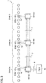
- a conveyor device 1 according to an embodiment of the present invention will be described below.
- the conveyor device 1 includes a plurality of zone conveyors 2 (2a, 2b, 2c, ...) arranged in series in a conveying direction.
- Each zone conveyor 2 (2a, 2b, 2c, ...) is a conveying device which mainly includes conveying rollers 5, a load presence sensor S (Sa, Sb, Sc, ...) and a zone controller 10 (10a, 10b, 10c, ).
- zone conveyors 2 (2a, 2b, 2c, 2d ) have the same mechanical configuration and the same size, a structure of the zone conveyor 2b disposed in the center of the figure will be described in detail as a representative example.
- the zone conveyor 2b is a device in which a plurality of conveying rollers 5 for conveying a conveying object are axially supported at predetermined interval in the conveying direction between a pair of left and right side frames 3, 3 disposed in parallel.
- the conveying rollers 5 includes a freely rotatable follower roller 5b and a motor-incorporated roller 5a incorporating a drive motor 4a (not illustrated in FIG. 2 ; see FIG. 3 ).
- a transmission belt 6 is wound around two adjacent conveying rollers 5 in the zone conveyor 2b. Therefore, a rotary drive force of the motor-incorporated roller 5a can be transmitted to all the follower rollers 5b.
- the motor-incorporated roller 5a is disposed in a center portion.
- the load presence sensor Sb is provided in the zone conveyor 2b.
- the load presence sensor Sb is provided on a side frame 3.
- the load presence sensor Sb is positioned near a downstream side end.
- the load presence sensor Sb is a photoelectric sensor and has a light emitting element 20 such as a light-emitting diode or an infrared diode on an opposing side frame 3.
- a light emitting element 20 such as a light-emitting diode or an infrared diode on an opposing side frame 3.
- the load presence sensor Sb When a conveying object is present, light from the light-emitting element 20 is shielded by the conveying object, causing the load presence sensor Sb to output an ON (High level) signal; whereas when the conveying object is absent, the load presence sensor Sb outputs an OFF (Low level) signal.
- ON/OF of the photoelectric sensor allows detection of a state where the conveying object has been conveyed to a predetermined position.
- the zone controller 10b for controlling drive of the drive motor 4a (see FIG. 3 ) incorporated in the motor-incorporated roller 5a is mounted to one side frame 3 of the zone conveyor 2b.
- a known brushless motor is adopted for the drive motor 4a.
- the zone controllers 10 (10a, ... 10c, ... 10n) provided in the two adjacent zone conveyors 2 (2a, 2b, 2c, 2d, ...) are connected to each other through a signal line 7. Further, at least one (in the present embodiment, zone conveyor 2a) of the zone controllers 10 (10a, ... 10n) is connected to a host controller 50 through a signal line 8.
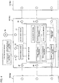
- FIG. 4 illustrates in further detail an internal configuration and a connection state of each of the zone controllers 10a to 10n. Since the zone controllers 10a to 10n have the same configuration, a configuration of the zone controller 10b will be described as a representative example.
- the zone controller 10b receives a signal from the load presence sensor Sb of the corresponding zone. That is, the zone controller 10b has a sensor signal input terminal 21.
- the zone controller 10b can transmit a light-emitting signal to the load presence sensor Sb and a pair of light emitting elements 20. That is, the zone controller 10b has a light-emitting element drive terminal 22.
- the zone controller 10b includes an arithmetic section 11, a signal input section 12, a signal transmission section 13, a sensor drive circuit 14, and a motor drive circuit 15.
- the signal input section 12 is connected to a right-side input terminal 25 and a left-side input terminal 28, individually processes a signal input from the right-side input terminal 25 and a signal input from the left-side input terminal 28, and outputs the processed signal to the arithmetic section 11.
- the signal input section 12 has a signal reception function to receive, in addition to a signal normally used for conveyance, an abnormality alarm signal from adjacent zone controllers 10a and 10c.
- the signal transmission section 13 is a circuit that transmits a signal output from the arithmetic section 11 to the outside, and is connected to a right-side output terminal 27 and a left-side output terminal 26.
- the signal transmission section 13 has a processed signal transmission function to transmit, in addition to a signal normally used for conveyance, a signal processed by a signal processing function to the outside as an abnormality alarm signal.
- the arithmetic section 11 incorporates therein a normal conveyance program for smoothly conveying a conveying object and a program specific to the present embodiment.
- the conveyance program includes an arithmetic circuit configured by a ZPA controller that performs zero-pressure accumulation control (ZPA control).
- the ZPA control is a control capable of avoiding collision between the conveying objects.
- the arithmetic section 11 refers to at least one of a signal input to the signal input section 12 and a signal output to the signal transmission section 13 to generate a control signal for driving the drive motor 4a and transmits the generated control signal to the motor drive circuit 15.
- the arithmetic section 11 performs an operation of receiving an external input signal such as a RUN/STOP signal from the host controller 50 and generating/transmitting a required control signal to the motor drive circuit 15.
- the arithmetic section 11 has a node number storage memory (storage unit) that stores a node number (to be described in detail later).
- the signal to be referred to by the arithmetic section 11 is selectively set by a not illustrated switch. That is, in the present embodiment, the conveyance program can be switched between a simultaneous conveyance mode, a separating conveyance mode, and a conveyance prohibiting mode, and the signal to be referred to by the arithmetic section 11 is selected according to the setting. Descriptions of the above conveyance modes are omitted.
- the motor drive circuit 15 drives the drive motor 4a while receiving the control signal from the arithmetic section 11 and a detection signal from a hall element (magnetic pole position detector, not illustrated) provided in the drive motor 4a incorporated in the motor-incorporated roller 5a.
- a hall element magnetic pole position detector, not illustrated
- a desired signal can be transmitted and received between the zone controllers 10.
- the zone controller 10 (zone controller 10b) of the present embodiment receives, through the signal input section 12, a load presence signal of the zone controller 10 (zone controller 10a) disposed adjacent thereto on an upstream side in the conveying direction of the conveying object, a load presence signal of the zone controller 10 (zone controller 10c) disposed adjacent thereto on a downstream side, and a drive state signal of the downstream side zone controller 10.
- the load presence signal and drive state signal output from the arithmetic section 11 of the zone controller 10b are transmitted to each of the other zone controllers 10a and 10c through the signal transmission section 13.
- the load presence signal is a detection signal of the load presence sensors Sa to Sc (see FIGS. 1 and 3 ) provided in the respective control zones.
- each of the zone controllers 10 can refer to the load presence signals of the respective upstream and downstream side zone controllers and the drive state signal of the downstream side zone controller.
- a command signal from the host controller 50 is transmitted to a predetermined zone controller 10 (zone controller 10a) through the signal line 8, and then transmitted from the predetermined zone controller 10 (zone controller 10a) to all the zone controllers constituting the conveyor device 1 (see FIG. 3 ).
- the zone controllers 10 exchange therebetween information on ON/OFF states of the load presence sensors S of adjacent zones and information on whether or not the drive motors 4a of the adjacent zones are activated.
- the zone controller activates the drive motor 4a of its corresponding zone when a predetermined condition, for example, that a conveying object is present in the corresponding zone and a conveying object is not present in a zone on the downstream side is satisfied, to convey the conveying object to the zone on the downstream side.
- the zone controller 10 of the present embodiment includes, in addition to the above program (conveyance program) for smoothly conveying a conveying object, a program (hereinafter, referred to as abnormality part detection program) for identifying a zone in which an abnormality has occurred.
- a program hereinafter, referred to as abnormality part detection program
- the abnormality part detection program includes an abnormality detection program (abnormality detection function), a signal creation program (signal creation function), and a signal processing program (signal processing function).
- the abnormality detection program (abnormality detection function) is a program that detects an abnormality that has occurred in the zone managed by itself.
- the abnormality may be arbitrarily determined and include, for example, disconnection of the drive motor 4a, overcurrent of the drive motor 4a, temperature abnormality of the drive motor 4a, disconnection of the sensor, detection abnormality of the sensor, sensor noise, abnormality of the light-emitting element 20, detection abnormality of a signal input from the zone controller 10 of another zone, signal transmission defect, supply voltage drop, and the like.
- the zone controller 10b can detect an abnormality of the zone controller 10 itself.
- the signal creation program functions when an abnormality is detected by the abnormality detection program (abnormality detection function), and generates a pulse signal of a fixed time.
- the signal creation program (signal creation function) generates a pulse signal having a fixed time length (reference length) at a fixed period on the condition that an abnormality is detected by the abnormality detection program (abnormality detection function).
- a length of the pulse signal is sufficiently shorter than the pulse period, and is set to, e.g., a length less than 1/20, more desirably, a length less than 1/50 of the pulse period.
- the pulse length is desirably equal to or more than 1/100 of the pulse period.
- the pulse period is set to 6 seconds, and the length (reference length) of the pulse to be generated is set to 0.1 seconds. That is, the period of the pulse signal to be generated is 6 seconds. Of the 6 seconds, ON time is 0.1 seconds, and OFF time is 5.9 seconds.
- the pulse signal created by the signal creation program (signal creation function) is distinguished from other signals and serves as an abnormality alarm signal.
- the abnormality alarm signal is passed through the signal transmission section 13 and is output from one of the output terminals. In the present embodiment, out of the right-side output terminal 27 and the left-side output terminal 26, the abnormality alarm signal is output from the left-side output terminal 26.
- the signal processing program functions when the abnormality alarm signal is input to the zone controller 10b from another zone controller 10, and extends the width of the pulse signal as the abnormality alarm signal by a fixed time.
- the pulse width is extended up to a length obtained by adding the original pulse length (reference length). Specifically, the length of the input abnormality alarm signal is extended by 0.1 seconds.
- the abnormality alarm signal having a length of 0.1 seconds is input, 0.1 seconds are added thereto to create a pulse having a length of 0.2 seconds, and the resultant signal is output from the left-side output terminal 26 as a new abnormality alarm signal.
- an abnormality alarm signal of 2.5 seconds is input, 0.1 seconds are added thereto to create a pulse having a length of 2.6 seconds, and the resultant signal is output from the left-side output terminal 26 as a new abnormality alarm signal.
- the conveyor device 1 of the present embodiment has a configuration in which the plurality of zone conveyors 2a, 2b, 2c, 2d, ... are arranged in series in the conveying direction.
- zone conveyors 2a, 2b, 2c, 2d, 2e, 2f, and 2g are arranged in series in the conveying direction.
- a failure retrieval device 30 is connected to any zone conveyor 2 (in the present embodiment, zone conveyor 2a).
- the failure retrieval device 30 is connected to the zone controller 10a of the zone conveyor 2a positioned at the end of the conveyor device 1.
- the failure retrieval device 30 is a device that receives the abnormality alarm signal output from the zone conveyor 2 and analyzes the received abnormality alarm signal.
- the abnormality alarm signal is output from the left-side output terminal 26, so that the failure retrieval device 30 is connected to the left-side output terminal 26 of the zone controller 10a.
- the failure retrieval device 30 detects the pulse length (pulse width) of the abnormality alarm signal and performs an arithmetic operation of dividing the detected pulse length by the reference length.
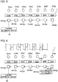
- the abnormality detection program (abnormality detection function) of the zone controller 10f that manages the zone in which the abnormality has occurred detects an occurrence of the abnormality.
- a pulse signal having a period of 6 seconds and a reference pulse length of 0.1 seconds (a pulse signal having a period of 6 seconds in which ON time is 0.1 seconds and OFF time is 5.9 seconds) is generated by the function of the signal processing program (signal processing function), and the generated pulse signal is passed through the signal transmission section 13 and is output, as the abnormality alarm signal, from the left-side output terminal 26 (see FIG. 6 ).
- the left-side output terminal 26 of the zone conveyor 2f is connected to the right-side input terminal 25 of the adjacent zone controller 10e, so that the abnormality alarm signal having a pulse length of 0.1 seconds created by the zone controller 10f as an abnormality generation source is input to the zone controller 10e adjacently disposed to the left side in the figure.
- the signal processing program creates a pulse signal having a pulse length of 0.2 seconds (a pulse signal having a period of 6 seconds in which ON time is 0.2 seconds and OFF time is 5.8 seconds) by adding the reference length to the input pulse signal. Then, the pulse signal having a pulse length of 0.2 seconds is output from the left-side output terminal 26 of the zone controller 10e as the abnormal alarm signal.
- the left-side output terminal 26 of the zone controller 10e is connected to the right-side input terminal 25 of the adjacent zone controller 10d, so that the abnormality alarm signal having a pulse length of 0.2 seconds created by the second zone controller 10f is input to the zone controller 10d adjacent to the left side in the figure, and the reference length is further added to create a pulse signal having a pulse length of 0.3 seconds (a pulse signal having a period of 6 seconds in which ON time is 0.3 seconds and OFF time is 5.7 seconds).
- the abnormality alarm signal having a pulse length of 0.3 seconds is input from the left-side output terminal 26 of the zone controller 10d to the adjacent zone controller 10c, and the reference length is further added to create a pulse signal having a pulse length of 0.4 seconds (having a period of 6 seconds in which ON time is 0.4 seconds and OFF time is 5.6 seconds).
- a pulse signal having a pulse length of 0.6 seconds (a pulse signal having a period of 6 seconds in which ON time is 0.6 seconds and OFF time is 5.4 seconds) is input from the zone controller 10a at the end portion to the failure retrieval device 30.
- the failure retrieval device 30 detects the length of the input pulse of the abnormality alarm signal, and performs an arithmetic operation of dividing the detected pulse length by the reference length.
- This arithmetic value coincides with the number of the zone controllers 10, including the zone controller 10f as the abnormality generation source, through which the pulse signal passes until it reaches the failure retrieval device 30.
- the zone controller 10f when the obtained arithmetic value is counted from the last zone controller 10a toward an upstream side in a transmission direction of the signal, the zone controller 10f as the abnormality generation source is reached.
- the zone conveyor 2f as the abnormality generation source can be identified.
- each zone controller 10g by inputting a pseudo abnormality alarm signal to a terminal end (most upstream side in the signal transmission direction) zone controller 10g, it is possible to allow each zone controller 10 to store its node number. This operation is specifically described below.
- a pulse signal (the same pulse signal as the above-described abnormality alarm signal) having a pulse length of 0.1 seconds is input to the right-side input terminal 25 of the terminal end zone controller 10g.
- a pseudo signal generation device is connected to the right-side input terminal 25 of the terminal end zone controller 10g. Then, a pulse signal having the reference pulse length is created in the pseudo signal generation device, and is input to the terminal end zone controller 10g as a pseudo abnormality alarm signal.
- the terminal end zone controller 10g determines the node number thereof in accordance with the pulse length of the input pulse signal, and stores the determined node number in the node number storage memory of the arithmetic section 11 (see FIG. 4 ). Since the pulse length of the pulse signal input to the zone controller lOg is 0.1 seconds, "1" is stored as the node number.
- the signal processing program adds the reference length to the pulse length of the pulse signal. That is, in the zone controller 10g, a pulse signal having a pulse length of 0.2 seconds (a pulse signal having a period of 6 seconds in which ON time is 0.2 seconds and OFF time is 5.8 seconds) is created.
- this pulse signal having a pulse length of 0.2 seconds is input to the zone controller 10f. That is, similarly to the abnormality alarm signal in the operation of detecting the zone conveyor 2, the generated pseudo abnormality alarm signal is input to the adjacent zone controller 10f.
- the zone controller 10f to which the pulse signal having a pulse length of 0.2 seconds is input determines the node number thereof in accordance with the pulse length of the input pulse signal, and stores the determined node number in the node number storage memory of the arithmetic section 11. Since the pulse length of the pulse signal input to the zone controller 10f is 0.2 seconds, "2" is stored as the node number.
- each zone controller 10 has a node number calculation function of calculating the node number from the pulse length of the input pulse signal. Then, the zone controller 10 performs operations of calculating the node number from the input pulse signal, storing the node number, processing the pulse signal, and outputting the processed pulse signal to the adjacent zone controller 10 (or failure retrieval device 30). Note that the processing of the pulse signal and the output of the processed pulse signal are performed in the same manner as those in the operation of detecting the zone conveyor 2 as the abnormality generation source.
- the node number is sequentially given to each zone controller 10 and the node number is stored in each zone controller 10.
- the command signal from the host controller 50 is transmitted to a predetermined zone controller 10 (zone controller 10a) through the signal line 8, and is then transmitted from the predetermined zone controller 10 (zone controller 10a) to all the zone controllers constituting the conveyor device 1 (see FIG. 3 ).
- the host controller 50 when the host controller 50 outputs a signal indicating the node number (or relevant information for indentifying the node number) and the command signal, the output signals are output from the predetermined zone controller 10 (zone controller 10a) to the adjacent zone controller 10 (zone controller 10b), and are thereafter successively output to the adjacent zone controllers 10.
- each zone controller 10 identifies whether or not the signal indicating the node number output together with the command signal indicates the node number of the zone controller 10 itself.
- the zone controller 10 When the node number coincides with the node number of the zone controller 10 itself, the zone controller 10 performs an operation instructed by the command signal, whereas when the node number does not coincide with the node number of the zone controller itself, the zone controller 10 does not perform an operation instructed by the transmitted command signal but outputs the input signal to the adjacent zone controller 10 as it is.
- predetermined zone controller 10 it is possible to allow only a predetermined zone controller 10 to change a conveying speed setting (slow start setting) in the zone conveyor 2 managed by the predetermined zone controller 10 itself. Furthermore, it is possible to allow only a predetermined zone controller 10 to perform program rewriting.
- the conveyor device 1 when the conveyor device 1 is operated in a state where the node number is stored in each zone controller 10, it is also possible to facilitate identification of the zone conveyor 2f as the abnormality generation source upon occurrence of any abnormality in the conveyor device 1.
- the zone controller 10 when an abnormality occurs, and the abnormality detection program of a zone controller 10 that manages the zone in which the abnormality occurs detects the occurrence of the abnormality, the zone controller 10 outputs a signal indicating the node number (or relevant information for identifying the node number) stored in the zone controller 10 itself and the abnormality alarm signal. At this time, another zone controller 10 outputs the input signals to the adjacent zone controller 10 (or failure retrieval device 30) as it is.
- the signals transmitted from the zone controller 10 in which the abnormality occurs are output to the failure retrieval device 30 as it is after passing through another zone controller as needed. Since the signal indicating the node number (or relevant information for identifying the node number) is included in the transmitted signal, the failure retrieval device 30 can identify the zone controller 10 of the zone in which the abnormality has occurred.
- the pseudo signal generation device is connected to the zone controller 10, and the pseudo abnormality alarm signal is output from the pseudo signal generation device to the terminal end zone controller 10g to make each zone controller 10 store its node number.
- the present invention is not limited thereto.
- any of the zone controller 10 outputs the pseudo abnormality alarm signal to make each zone controller store its node number.
- a timing at which each zone controller is made to store its node number is not limited to the test run time.
- the operation of making each zone controller store its node number may be automatically performed when the conveyor device 1 is powered ON.
- the failure retrieval device 30 is connected to the zone controller 10a at the end portion so as to retrieve the failure part.
- the failure retrieval device 30 may be connected to any position as long as it is located on the downstream side of the failure part in the signal transmission direction.
- a pulse signal having a pulse length of 0.4 seconds is input to the failure retrieval device 30 and, thus, the failure retrieval device 30 can identify the failure part.
- the pulse length is increased.
- the number of pulses to be generated may be increased.
- the signal processing program may be configured to add, when the abnormality alarm signal is input from another zone controller, a pulse having a predetermined length (e.g., reference length of 0.1 seconds) to the abnormality alarm signal.
- a pulse having a predetermined length e.g., reference length of 0.1 seconds
- the number of pulses is increased by one every time the abnormality alarm signal passes through the zone controller.
- the failure retrieval device 30 it is possible to identify a failure part simply by acquiring the number of pulses using the failure retrieval device 30.
- the pulse length or the number of pulses may be reduced every time the abnormality alarm signal passes through the zone controller.
- the signal processing function may be a function that processes the pulse signal based on a function following a fixed rule.
- one zone conveyor 2 is controlled by one zone controller 10.
- the conveyor device of the present invention is not limited thereto.
- the conveyor device may be adopted in which a plurality of the zone conveyors may be controlled by one zone controller. Also in this case, by identifying the zone controller that manages the zone conveyor in the zone in which the failure has occurred, it is possible to identify the failure part in the conveyor device.
- a roller conveyor is adopted as the zone conveyor 2.
- the conveyor device of the present invention is not limited thereto.
- a belt conveyor may be adopted as the zone conveyor.
Landscapes
- Engineering & Computer Science (AREA)
- Physics & Mathematics (AREA)
- General Physics & Mathematics (AREA)
- Automation & Control Theory (AREA)
- General Engineering & Computer Science (AREA)
- Manufacturing & Machinery (AREA)
- Quality & Reliability (AREA)
- Control Of Conveyors (AREA)
- Control Of Electric Motors In General (AREA)
Claims (15)
- Zonensteuersystem (10b), das zur Verwendung für eine Fördervorrichtung (1) ausgebildet ist,
wobei in der Fördervorrichtung (1) mehrere Zonenförderer (2) in Reihe angeordnet sind,
wobei das Zonensteuersystem (10b) dazu ausgebildet ist, einen oder mehrere der Zonenförderer (2) zu betreiben, um deren Betrieb zu steuern, und
wobei das Zonensteuersystem (10b) dazu ausgebildet ist, ein Signal von einem ersten Zonensteuersystem (10a) zu empfangen und ein Signal an ein nächstes Zonensteuersystem (10c) zu übertragen,
dadurch gekennzeichnet,
dass das Zonensteuersystem (10b) dazu ausgebildet ist, die folgenden Funktionen auszuüben:- eine Signalerzeugungsfunktion, die dazu ausgebildet ist, ein vorbestimmtes Anomalie-Alarmsignal zu erzeugen, das ein Impulssignal mit einer festen Zeitlänge ist, und das erzeugte Anomalie-Alarmsignal an das nächste Zonensteuersystem (10c) zu übertragen, wenn eine Anomalie in einer von dem Zonensteuersystem (10b) selbst betriebenen Zone auftritt;- eine Signalempfangsfunktion, die dazu ausgebildet ist, ein Anomalie-Alarmsignal von dem ersten Zonensteuersystem (10a) zu empfangen;- eine Signalverarbeitungsfunktion, die dazu ausgebildet ist, eine bestimmte Verarbeitung anzuwenden, indem sie das empfangene Anomalie-Alarmsignal durch Erhöhen oder Verringern der Impulsbreite oder der Anzahl von Impulsen um ein Merkmal ergänzt; und- eine Funktion zur Übertragung des verarbeiteten Signals, die dazu ausgebildet ist, das durch die Signalverarbeitungsfunktion verarbeitete Signal als das Anomalie-Alarmsignal an das nächste Zonensteuersystem (10c) zu übertragen. - Zonensteuersystem (10b) nach Anspruch 1,
wobei dann, wenn die Signalverarbeitungsfunktion ein Merkmal ergänzt, die Signalverarbeitungsfunktion dazu ausgebildet ist, einen neuen Impuls zu dem empfangenen Anomalie-Alarmsignal, das ein Impulssignal ist, zu addieren oder davon zu subtrahieren, um die Anzahl der Impulse zu erhöhen oder zu verringern. - Zonensteuersystem (10b), das zur Verwendung für eine Fördervorrichtung (1) ausgebildet ist,
wobei in der Fördervorrichtung (1) mehrere Zonenförderer (2) in Reihe angeordnet sind,
wobei das Zonensteuersystem (10b) dazu ausgebildet ist, einen oder mehrere der Zonenförderer (2) zu betreiben, um deren Betrieb zu steuern, und
wobei das Zonensteuersystem (10b) dazu ausgebildet ist, ein Signal von einem ersten Zonensteuersystem (10a) zu empfangen und ein Signal an ein nächstes Zonensteuersystem (10c) zu übertragen,
dadurch gekennzeichnet,
dass das Zonensteuersystem (10b) dazu ausgebildet ist, die folgenden Funktionen auszuüben:- eine Signalempfangsfunktion, die dazu ausgebildet ist, ein Impulssignal von dem ersten Zonensteuersystem (10a) zu empfangen;- eine Signalverarbeitungsfunktion, die dazu ausgebildet ist, eine bestimmte Verarbeitung anzuwenden, indem sie das empfangene Impulssignal, basierend auf einer bestimmten Funktion durch Erhöhen oder Verringern der Impulsbreite oder der Anzahl von Impulsen um ein Merkmal ergänzt;- eine Funktion zur Übertragung des verarbeiteten Signals, die dazu ausgebildet ist, das durch die Signalverarbeitungsfunktion verarbeitete Signal an das nächste Zonensteuersystem (10c) zu übertragen; undwobei das Zonensteuersystem eine Speichereinheit aufweist, die dazu ausgebildet ist, das von dem Zonensteuersystem (10b) selbst verarbeitete Signal zu speichern. - Zonensteuersystem (10b) nach Anspruch 3,
das ferner eine Signalerzeugungsfunktion aufweist, die dazu ausgebildet ist, ein vorbestimmtes Anomalie-Alarmsignal zu erzeugen und das erzeugte Anomalie-Alarmsignal an das nächste Zonensteuersystem (10c) zu übertragen, wenn eine Anomalie in einer von dem Zonensteuersystem (10b) selbst betriebenen Zone auftritt,
wobei das Zonensteuersystem (10b) dazu ausgebildet ist, das Anomalie-Alarmsignal und ein Signal basierend auf den in der Speichereinheit gespeicherten Informationen zu übertragen,
wobei die Informationen, die in der Speichereinheit gespeicherten sind, Informationen sind, die sich auf Knotennummer beziehen, die die Knotennummer selbst oder relevante Informationen zur Identifizierung der Knotennummer sind. - Zonensteuersystem (10b) nach Anspruch 3 oder 4,
das ferner eine Knotennummer-Berechnungsfunktion aufweist, die dazu ausgebildet ist, eine Knotennummer des Zonensteuersystems (10b) selbst, basierend auf dem empfangenen Impulssignal zu bestimmen,
wobei Informationen, die sich auf die von der Knotennummern-Bestimmungsfunktion erzeugte Knotennummer beziehen, in der Speichereinheit gespeichert sind,
wobei die Informationen, die sich auf die Knotennummer beziehen, die Knotennummer selbst oder relevante Informationen zur Identifizierung der Knotennummer sind. - Zonensteuersystem (10b) nach Anspruch 5,
wobei die Knotennummer-Berechnungsfunktion dazu ausgebildet ist, die Knotennummer basierend auf einer Impulsbreite oder der Anzahl von Impulsen des empfangenen Impulssignals zu bestimmen. - Zonensteuersystem (10b) nach einem der Ansprüche 3 bis 6,
das ferner eine Signalerzeugungsfunktion aufweist, die dazu ausgebildet ist, ein vorbestimmtes Anomalie-Alarmsignal zu erzeugen und das erzeugte Anomalie-Alarmsignal an das nächste Zonensteuersystem (10c) zu übertragen, wenn eine Anomalie in einer von dem Zonensteuersystem (10b) selbst betriebenen Zone auftritt,
wobei die Speichereinheit dazu ausgebildet ist, Informationen in Bezug auf die Knotennummer zu speichern, die die Knotennummer selbst oder relevante Informationen zur Identifizierung der Knotennummer sind, und
wobei die Funktion zur Übertragung des verarbeiteten Signals dazu ausgebildet ist, sowohl ein Signal, das die auf die Knotennummer bezogene Information anzeigt, als auch das Anomalitätsalarmsignal auszugeben. - Zonensteuersystem (10b) nach einem der Ansprüche 1 bis 7,
das dazu ausgebildet ist, ein Pseudo-Anomalie-Alarmsignal auszugeben. - Fördervorrichtung (1), bei der mehrere Zonenförderer (2) in Reihe angeordnet sind, wobei die Fördervorrichtung (1) ein Zonensteuersystem (10b) nach einem der Ansprüche 1 oder 2 für jede Zone oder für jeden Satz von mehreren Zonen aufweist, und bei der zwischen den benachbarten Zonensteuersystemen (10a, 10c) ein Signal ausgetauscht wird,
wobei dann, wenn das Zonensteuersystem (10b) das vorbestimmte Signal von einem Zonensteuersystem (10a), das benachbart auf einer Seite davon angeordnet ist, durch die Signalempfangsfunktion empfängt, das Zonensteuersystem (10b) dazu ausgebildet ist, das durch die Signalverarbeitungsfunktion verarbeitete Signal als ein Anomalie-Alarmsignal an ein Zonensteuersystem (10c) zu übertragen, das benachbart auf der anderen Seite davon angeordnet ist. - Fördervorrichtung (1) nach Anspruch 9,
wobei ein Pseudo-Anomalie-Alarmsignal erzeugt und an das Zonensteuersystem (10) übertragen wird,
wobei die Zonensteuersysteme (10), die das Pseudo-Anomalie-Alarmsignal empfangen, dazu ausgebildet sind, sukzessive einen Prozess der Anwendung der Verarbeitung durchzuführen, indem sie ein Merkmal zu dem empfangenen Signal durch die Signalverarbeitungsfunktion ergänzen und das verarbeitete Signal an Zonensteuersysteme (10) übertragen, die benachbart auf der anderen Seite davon angeordnet sind, und
wobei jedes der Zonensteuersysteme (10) derart ausgebildet ist, dass es das von dem Zonensteuersystem (10) verarbeitete Signal selbst oder Informationen mit Bezug auf das verarbeitete Signal speichert. - Fördervorrichtung (1), bei der mehrere Zonenförderer (2) in Reihe angeordnet sind, wobei die Fördervorrichtung (1) ein Zonensteuersystem (10) nach einem der Ansprüche 3 bis 8 für jede Zone oder für jeden Satz von mehreren Zonen aufweist, und bei der zwischen den benachbarten Zonensteuersystemen (10) ein Signal ausgetauscht wird,- wobei jedes der Zonensteuersysteme (10) eine Knotennummer-Berechnungsfunktion aufweist, die dazu ausgebildet ist, eine Knotennummer des Zonensteuersystems (10) selbst, basierend auf einer Pulsbreite oder der Anzahl von Pulsen des empfangenen Pulssignals zu bestimmen, und eine Speichereinheit aufweist, die dazu ausgebildet ist, die Knotennummer zu speichern,- wobei jedes der Zonensteuersysteme (10) derart ausgebildet ist, einen Knotennummern-Bestimmungsvorgang auszuführen, zum Bestimmen der Knotennummer auf Grundlage des empfangenen Signals, Speichern der bestimmten Knotennummer, Verarbeiten des empfangenen Signals durch die Signalverarbeitungsfunktion und Übertragen des verarbeiteten Signals an das benachbarte Zonensteuersystem (10) durch die Übertragungsfunktion für verarbeitete Signale, und- wobei die sukzessive Ausführung des Knotennummern-Bestimmungsvorgangs in den Zonensteuersystemen (10) es jedem der Zonensteuersysteme (10) ermöglicht, die Knotennummer darin zu speichern.
- Fördervorrichtung (1) nach Anspruch 11,
wobei jedes der Zonensteuersysteme (10) dazu ausgebildet ist, die Knotennummer auf der Grundlage eines Pseudo-Anomalie-Alarmsignals oder eines durch Verarbeitung des Anomalie-Alarmsignals erhaltenen Signals zu bestimmen und zu speichern, und
wobei der Knotennummer-Bestimmungsvorgang ausgeführt wird auf der Grundlage von einem von einem Pseudo-Anomalie-Alarmsignal, erzeugt von mindestens einem Zonensteuersystem (10), einem Pseudo-Anomalie-Alarmsignal, übertragen von einer externen Vorrichtung, und einem Signal, erhalten durch Verarbeiten des Pseudo-Anomalie-Alarmsignals. - Fördervorrichtung (1) nach Anspruch 11 oder Anspruch 12,
wobei dann, wenn die Knotennummer in jedem der Zonensteuersysteme (10) gespeichert ist,
wobei jedes der Zonensteuersysteme (10) ausgebildet ist, einen individuellen Befehlsvorgang auszuführen, um ein Signal, das Informationen bezüglich der Knotennummer anzeigt, und ein Befehlssignal zu empfangen, einen durch das Befehlssignal spezifizierten Vorgang auszuführen, wenn die empfangenen Informationen mit Bezug auf die Knotennummer die Knotennummer des Zonensteuersystems (10) selbst identifizieren, und das empfangene Signal, das die Informationen mit Bezug auf die Knotennummer anzeigt, und das Befehlssignal ohne Verarbeitung der Signale an das benachbarte Zonensteuersystem (10) zu übertragen, und
wobei die sukzessive Ausführung des individuellen Befehlsvorgangs in den Zonensteuersystemen (10) es nur einem vorbestimmten Zonensteuersystem (10) ermöglicht, einen durch das Befehlssignal spezifizierten Vorgang durchzuführen. - Fördervorrichtung (1) nach einem der Ansprüche 9 bis 13 in Verbindung mit Anspruch 7,
wobei jedes der Zonensteuersysteme (10) dazu ausgebildet ist, beim Auftreten einer Anomalie in einer von dem Zonensteuersystem (10) selbst betriebenen Zone zwei Signale auszugeben, nämlich das Signal, das die Information mit Bezug auf die Knotennummer angibt, und das Anomalie-Alarmsignal an das benachbarte Zonensteuersystem (10), und wobei das Zonensteuersystem (10), das die beiden Signale von einem auf einer Seite davon benachbart angeordneten Zonensteuersystem (10) empfängt, dazu ausgebildet ist, die beiden Signale an ein auf der anderen Seite davon benachbart angeordnetes Zonensteuersystem (10) auszugeben, ohne diese Signale zu verarbeiten. - Fördervorrichtung (1) nach einem der Ansprüche 9 bis 14,
wobei dann, wenn die Zonensteuersysteme (10) dazu ausgebildet sind, sukzessive den Vorgang einer Verarbeitung durch Ergänzen eines Merkmals an das empfangene Signal auszuführen und das verarbeitete Signal an die benachbarten Zonensteuersysteme (10) zu übertragen, das Signal vor der Verarbeitung und das Signal nach der Verarbeitung, die zwischen den Zonensteuersystemen (10) ausgetauscht werden, eine feste Periode aufweisen, sich aber in der Pulsbreite oder der Anzahl der Pulse unterscheiden.
Applications Claiming Priority (2)
| Application Number | Priority Date | Filing Date | Title |
|---|---|---|---|
| JP2012062182 | 2012-03-19 | ||
| PCT/JP2013/056692 WO2013141066A1 (ja) | 2012-03-19 | 2013-03-11 | ゾーンコントローラ、並びに、コンベア装置 |
Publications (3)
| Publication Number | Publication Date |
|---|---|
| EP2829496A1 EP2829496A1 (de) | 2015-01-28 |
| EP2829496A4 EP2829496A4 (de) | 2016-01-06 |
| EP2829496B1 true EP2829496B1 (de) | 2021-05-26 |
Family
ID=49222526
Family Applications (1)
| Application Number | Title | Priority Date | Filing Date |
|---|---|---|---|
| EP13764466.2A Active EP2829496B1 (de) | 2012-03-19 | 2013-03-11 | Zonensteuerung und fördervorrichtung |
Country Status (4)
| Country | Link |
|---|---|
| US (1) | US9446907B2 (de) |
| EP (1) | EP2829496B1 (de) |
| JP (1) | JP6142231B2 (de) |
| WO (1) | WO2013141066A1 (de) |
Families Citing this family (11)
| Publication number | Priority date | Publication date | Assignee | Title |
|---|---|---|---|---|
| JP6217491B2 (ja) * | 2014-03-27 | 2017-10-25 | 村田機械株式会社 | 搬送制御システム及びデータ処理装置 |
| US10322883B2 (en) * | 2014-11-18 | 2019-06-18 | Itoh Denki Co. | Conveyor device, conveyor system, zone controller, CAD device, and method for manufacturing conveyor device |
| US10222775B2 (en) | 2015-11-30 | 2019-03-05 | Hubbell Incorporated | Interrupt exception window protocol on a data communication bus and methods and apparatuses for using same |
| US10341135B2 (en) * | 2015-12-30 | 2019-07-02 | Nova-Tron Controls Corp. | Zone control system for conveyor system |
| WO2018213827A1 (en) * | 2017-05-19 | 2018-11-22 | Span Tech Llc | Adjustable conveyor belt guiderail and related methods |
| US10889451B2 (en) * | 2018-10-17 | 2021-01-12 | Intelligrated Headquarters, Llc | System and method for controlling an accumulation conveyor |
| EP3950545A4 (de) * | 2019-04-05 | 2022-12-28 | Itoh Denki Co., Ltd. | Fördersystem, vorrichtung zum melden von ursacheninformationen, programm für die vorrichtung zum melden von ursacheninformationen und computerlesbares aufzeichnungsmedium mit darauf aufgezeichnetem programm für die vorrichtung zum melden von ursacheninformationen |
| JP7149607B2 (ja) | 2019-10-25 | 2022-10-07 | 伊東電機株式会社 | コンベヤシステム |
| WO2021087855A1 (en) * | 2019-11-07 | 2021-05-14 | Nokia Shanghai Bell Co., Ltd. | Counting of devices |
| US20220342389A1 (en) * | 2021-04-27 | 2022-10-27 | Stephenson Technologies Inc. | System for controlling a vehicle conveyor, and a vehicle wash having the same |
| CN116915821B (zh) * | 2023-07-25 | 2024-03-12 | 河南省通信建设管理咨询有限公司 | 一种基于5g的工程管理平台 |
Family Cites Families (13)
| Publication number | Priority date | Publication date | Assignee | Title |
|---|---|---|---|---|
| JPH0281817A (ja) | 1988-09-16 | 1990-03-22 | Daifuku Co Ltd | 仕分け設備 |
| AU634261B2 (en) | 1989-08-09 | 1993-02-18 | Tasman Cable Company Pty. Limited (Tcc) | Fault location arrangement for digital transmission system |
| JP2002356220A (ja) | 2001-03-28 | 2002-12-10 | Hitachi Ltd | ローラコンベアシステム |
| JP3873095B2 (ja) | 2001-06-20 | 2007-01-24 | 伊東電機株式会社 | ゾーンコントローラ |
| JP2005231745A (ja) * | 2001-06-27 | 2005-09-02 | Ito Denki Kk | ゾーンコントローラ |
| US6827202B2 (en) * | 2001-12-21 | 2004-12-07 | Balluff, Inc. | Methods and apparatus for controlling conveyor zones |
| JP3845659B2 (ja) | 2002-05-08 | 2006-11-15 | 伊東電機株式会社 | 搬送装置 |
| US6961374B2 (en) | 2003-02-21 | 2005-11-01 | Direction Technology Co., Ltd. | Pulse data coding method for wireless signal transmitting and receiving devices |
| ES2287440T3 (es) * | 2003-03-19 | 2007-12-16 | Cavanna S.P.A. | Dispositivo de transporte de articulos, en particular para maquinaria de embalaje automatica y procedimiento de uso correspondiente. |
| US7272744B2 (en) | 2004-05-19 | 2007-09-18 | Micrel, Incorporated | Method for signaling during a transaction and receiving unit and system for use therewith |
| JP2004307219A (ja) | 2004-07-26 | 2004-11-04 | Ito Denki Kk | コンベアシステムの制御装置並びに方法、及び、コンベアシステムのモニタリング装置 |
| JP4979658B2 (ja) | 2008-08-28 | 2012-07-18 | 株式会社 エニイワイヤ | 搬送制御システム及び搬送制御方法 |
| US8042681B2 (en) * | 2008-10-30 | 2011-10-25 | Worldwide Logistics Corporation | Drive roller controller for an accumulating conveyor system |
-
2013
- 2013-03-11 US US14/386,180 patent/US9446907B2/en active Active
- 2013-03-11 WO PCT/JP2013/056692 patent/WO2013141066A1/ja not_active Ceased
- 2013-03-11 EP EP13764466.2A patent/EP2829496B1/de active Active
- 2013-03-11 JP JP2014506147A patent/JP6142231B2/ja active Active
Non-Patent Citations (1)
| Title |
|---|
| None * |
Also Published As
| Publication number | Publication date |
|---|---|
| EP2829496A1 (de) | 2015-01-28 |
| EP2829496A4 (de) | 2016-01-06 |
| JP6142231B2 (ja) | 2017-06-07 |
| US20150068871A1 (en) | 2015-03-12 |
| JPWO2013141066A1 (ja) | 2015-08-03 |
| US9446907B2 (en) | 2016-09-20 |
| WO2013141066A1 (ja) | 2013-09-26 |
Similar Documents
| Publication | Publication Date | Title |
|---|---|---|
| EP2829496B1 (de) | Zonensteuerung und fördervorrichtung | |
| JP4122392B2 (ja) | ゾーンコントローラ | |
| JP6563033B2 (ja) | 搬送装置の設置方法 | |
| EP2933662B1 (de) | Fotoelektronischer Sensor mit mehreren optischen Achsen | |
| JP6669776B2 (ja) | ハードウェア検出を備えたコンベヤの制御ユニット | |
| US6827202B2 (en) | Methods and apparatus for controlling conveyor zones | |
| KR101215430B1 (ko) | 운송제어 시스템 및 운송제어 방법 | |
| US8996160B2 (en) | Article storage device and conveyor used therein | |
| EP2983013B1 (de) | Photoelektrischer sensor mit mehreren optischen achsen und steuerungsverfahren | |
| US12275599B2 (en) | Conveyor system, cause information report device, and computer-readable recording medium recording program for cause information report device | |
| JP5404734B2 (ja) | コンベア装置、集合型ゾーンコントローラ、並びにゾーンコントローラ | |
| JP2013199359A (ja) | コンベア装置、並びに、ゾーンコントローラ | |
| JP7718714B2 (ja) | 搬送装置 | |
| US20230382654A1 (en) | Non-plc-based conveyor controller | |
| EP3582244B1 (de) | Photoelektrischer sensor und lichtprojektor | |
| WO2016147254A1 (ja) | 搬送システム | |
| JP3546832B2 (ja) | ゾーン制御方式コンベアシステム、並びに、信号割込装置 | |
| JP5170756B2 (ja) | コンベア装置 | |
| JP5170754B2 (ja) | コンベア装置 | |
| JP2002284334A (ja) | コンベアの制御装置 | |
| EP4624383A1 (de) | Verfahren zur steuerung eines stauförderers | |
| KR20250132225A (ko) | 파워 몰러 컨베이어의 구동 제어장치 및 방법 | |
| EP3699696B1 (de) | Sicheres rollensteuergerät eines rollenförderersystem für logistikdienste | |
| EP2674823A1 (de) | Notfallmanagementsystem | |
| JPH0723730U (ja) | コンベアの制御装置 |
Legal Events
| Date | Code | Title | Description |
|---|---|---|---|
| PUAI | Public reference made under article 153(3) epc to a published international application that has entered the european phase |
Free format text: ORIGINAL CODE: 0009012 |
|
| 17P | Request for examination filed |
Effective date: 20141017 |
|
| AK | Designated contracting states |
Kind code of ref document: A1 Designated state(s): AL AT BE BG CH CY CZ DE DK EE ES FI FR GB GR HR HU IE IS IT LI LT LU LV MC MK MT NL NO PL PT RO RS SE SI SK SM TR |
|
| AX | Request for extension of the european patent |
Extension state: BA ME |
|
| DAX | Request for extension of the european patent (deleted) | ||
| RA4 | Supplementary search report drawn up and despatched (corrected) |
Effective date: 20151209 |
|
| RIC1 | Information provided on ipc code assigned before grant |
Ipc: G05B 19/418 20060101ALI20151203BHEP Ipc: B65G 43/00 20060101AFI20151203BHEP Ipc: G05B 19/042 20060101ALI20151203BHEP Ipc: B65G 43/10 20060101ALI20151203BHEP |
|
| STAA | Information on the status of an ep patent application or granted ep patent |
Free format text: STATUS: EXAMINATION IS IN PROGRESS |
|
| 17Q | First examination report despatched |
Effective date: 20190410 |
|
| GRAP | Despatch of communication of intention to grant a patent |
Free format text: ORIGINAL CODE: EPIDOSNIGR1 |
|
| STAA | Information on the status of an ep patent application or granted ep patent |
Free format text: STATUS: GRANT OF PATENT IS INTENDED |
|
| INTG | Intention to grant announced |
Effective date: 20201210 |
|
| GRAS | Grant fee paid |
Free format text: ORIGINAL CODE: EPIDOSNIGR3 |
|
| GRAA | (expected) grant |
Free format text: ORIGINAL CODE: 0009210 |
|
| STAA | Information on the status of an ep patent application or granted ep patent |
Free format text: STATUS: THE PATENT HAS BEEN GRANTED |
|
| AK | Designated contracting states |
Kind code of ref document: B1 Designated state(s): AL AT BE BG CH CY CZ DE DK EE ES FI FR GB GR HR HU IE IS IT LI LT LU LV MC MK MT NL NO PL PT RO RS SE SI SK SM TR |
|
| REG | Reference to a national code |
Ref country code: GB Ref legal event code: FG4D |
|
| REG | Reference to a national code |
Ref country code: CH Ref legal event code: EP |
|
| REG | Reference to a national code |
Ref country code: AT Ref legal event code: REF Ref document number: 1396042 Country of ref document: AT Kind code of ref document: T Effective date: 20210615 |
|
| REG | Reference to a national code |
Ref country code: DE Ref legal event code: R096 Ref document number: 602013077666 Country of ref document: DE |
|
| REG | Reference to a national code |
Ref country code: IE Ref legal event code: FG4D |
|
| REG | Reference to a national code |
Ref country code: LT Ref legal event code: MG9D |
|
| REG | Reference to a national code |
Ref country code: AT Ref legal event code: MK05 Ref document number: 1396042 Country of ref document: AT Kind code of ref document: T Effective date: 20210526 |
|
| PG25 | Lapsed in a contracting state [announced via postgrant information from national office to epo] |
Ref country code: HR Free format text: LAPSE BECAUSE OF FAILURE TO SUBMIT A TRANSLATION OF THE DESCRIPTION OR TO PAY THE FEE WITHIN THE PRESCRIBED TIME-LIMIT Effective date: 20210526 Ref country code: AT Free format text: LAPSE BECAUSE OF FAILURE TO SUBMIT A TRANSLATION OF THE DESCRIPTION OR TO PAY THE FEE WITHIN THE PRESCRIBED TIME-LIMIT Effective date: 20210526 Ref country code: BG Free format text: LAPSE BECAUSE OF FAILURE TO SUBMIT A TRANSLATION OF THE DESCRIPTION OR TO PAY THE FEE WITHIN THE PRESCRIBED TIME-LIMIT Effective date: 20210826 Ref country code: FI Free format text: LAPSE BECAUSE OF FAILURE TO SUBMIT A TRANSLATION OF THE DESCRIPTION OR TO PAY THE FEE WITHIN THE PRESCRIBED TIME-LIMIT Effective date: 20210526 Ref country code: LT Free format text: LAPSE BECAUSE OF FAILURE TO SUBMIT A TRANSLATION OF THE DESCRIPTION OR TO PAY THE FEE WITHIN THE PRESCRIBED TIME-LIMIT Effective date: 20210526 |
|
| REG | Reference to a national code |
Ref country code: NL Ref legal event code: MP Effective date: 20210526 |
|
| PG25 | Lapsed in a contracting state [announced via postgrant information from national office to epo] |
Ref country code: GR Free format text: LAPSE BECAUSE OF FAILURE TO SUBMIT A TRANSLATION OF THE DESCRIPTION OR TO PAY THE FEE WITHIN THE PRESCRIBED TIME-LIMIT Effective date: 20210827 Ref country code: IS Free format text: LAPSE BECAUSE OF FAILURE TO SUBMIT A TRANSLATION OF THE DESCRIPTION OR TO PAY THE FEE WITHIN THE PRESCRIBED TIME-LIMIT Effective date: 20210926 Ref country code: LV Free format text: LAPSE BECAUSE OF FAILURE TO SUBMIT A TRANSLATION OF THE DESCRIPTION OR TO PAY THE FEE WITHIN THE PRESCRIBED TIME-LIMIT Effective date: 20210526 Ref country code: RS Free format text: LAPSE BECAUSE OF FAILURE TO SUBMIT A TRANSLATION OF THE DESCRIPTION OR TO PAY THE FEE WITHIN THE PRESCRIBED TIME-LIMIT Effective date: 20210526 Ref country code: SE Free format text: LAPSE BECAUSE OF FAILURE TO SUBMIT A TRANSLATION OF THE DESCRIPTION OR TO PAY THE FEE WITHIN THE PRESCRIBED TIME-LIMIT Effective date: 20210526 Ref country code: NO Free format text: LAPSE BECAUSE OF FAILURE TO SUBMIT A TRANSLATION OF THE DESCRIPTION OR TO PAY THE FEE WITHIN THE PRESCRIBED TIME-LIMIT Effective date: 20210826 Ref country code: PL Free format text: LAPSE BECAUSE OF FAILURE TO SUBMIT A TRANSLATION OF THE DESCRIPTION OR TO PAY THE FEE WITHIN THE PRESCRIBED TIME-LIMIT Effective date: 20210526 Ref country code: PT Free format text: LAPSE BECAUSE OF FAILURE TO SUBMIT A TRANSLATION OF THE DESCRIPTION OR TO PAY THE FEE WITHIN THE PRESCRIBED TIME-LIMIT Effective date: 20210927 |
|
| PG25 | Lapsed in a contracting state [announced via postgrant information from national office to epo] |
Ref country code: NL Free format text: LAPSE BECAUSE OF FAILURE TO SUBMIT A TRANSLATION OF THE DESCRIPTION OR TO PAY THE FEE WITHIN THE PRESCRIBED TIME-LIMIT Effective date: 20210526 |
|
| PG25 | Lapsed in a contracting state [announced via postgrant information from national office to epo] |
Ref country code: RO Free format text: LAPSE BECAUSE OF FAILURE TO SUBMIT A TRANSLATION OF THE DESCRIPTION OR TO PAY THE FEE WITHIN THE PRESCRIBED TIME-LIMIT Effective date: 20210526 Ref country code: ES Free format text: LAPSE BECAUSE OF FAILURE TO SUBMIT A TRANSLATION OF THE DESCRIPTION OR TO PAY THE FEE WITHIN THE PRESCRIBED TIME-LIMIT Effective date: 20210526 Ref country code: EE Free format text: LAPSE BECAUSE OF FAILURE TO SUBMIT A TRANSLATION OF THE DESCRIPTION OR TO PAY THE FEE WITHIN THE PRESCRIBED TIME-LIMIT Effective date: 20210526 Ref country code: CZ Free format text: LAPSE BECAUSE OF FAILURE TO SUBMIT A TRANSLATION OF THE DESCRIPTION OR TO PAY THE FEE WITHIN THE PRESCRIBED TIME-LIMIT Effective date: 20210526 Ref country code: DK Free format text: LAPSE BECAUSE OF FAILURE TO SUBMIT A TRANSLATION OF THE DESCRIPTION OR TO PAY THE FEE WITHIN THE PRESCRIBED TIME-LIMIT Effective date: 20210526 Ref country code: SK Free format text: LAPSE BECAUSE OF FAILURE TO SUBMIT A TRANSLATION OF THE DESCRIPTION OR TO PAY THE FEE WITHIN THE PRESCRIBED TIME-LIMIT Effective date: 20210526 Ref country code: SM Free format text: LAPSE BECAUSE OF FAILURE TO SUBMIT A TRANSLATION OF THE DESCRIPTION OR TO PAY THE FEE WITHIN THE PRESCRIBED TIME-LIMIT Effective date: 20210526 |
|
| REG | Reference to a national code |
Ref country code: DE Ref legal event code: R097 Ref document number: 602013077666 Country of ref document: DE |
|
| PLBE | No opposition filed within time limit |
Free format text: ORIGINAL CODE: 0009261 |
|
| STAA | Information on the status of an ep patent application or granted ep patent |
Free format text: STATUS: NO OPPOSITION FILED WITHIN TIME LIMIT |
|
| 26N | No opposition filed |
Effective date: 20220301 |
|
| PG25 | Lapsed in a contracting state [announced via postgrant information from national office to epo] |
Ref country code: IS Free format text: LAPSE BECAUSE OF FAILURE TO SUBMIT A TRANSLATION OF THE DESCRIPTION OR TO PAY THE FEE WITHIN THE PRESCRIBED TIME-LIMIT Effective date: 20210926 Ref country code: AL Free format text: LAPSE BECAUSE OF FAILURE TO SUBMIT A TRANSLATION OF THE DESCRIPTION OR TO PAY THE FEE WITHIN THE PRESCRIBED TIME-LIMIT Effective date: 20210526 |
|
| PG25 | Lapsed in a contracting state [announced via postgrant information from national office to epo] |
Ref country code: IT Free format text: LAPSE BECAUSE OF FAILURE TO SUBMIT A TRANSLATION OF THE DESCRIPTION OR TO PAY THE FEE WITHIN THE PRESCRIBED TIME-LIMIT Effective date: 20210526 |
|
| PG25 | Lapsed in a contracting state [announced via postgrant information from national office to epo] |
Ref country code: MC Free format text: LAPSE BECAUSE OF FAILURE TO SUBMIT A TRANSLATION OF THE DESCRIPTION OR TO PAY THE FEE WITHIN THE PRESCRIBED TIME-LIMIT Effective date: 20210526 |
|
| REG | Reference to a national code |
Ref country code: CH Ref legal event code: PL |
|
| REG | Reference to a national code |
Ref country code: BE Ref legal event code: MM Effective date: 20220331 |
|
| PG25 | Lapsed in a contracting state [announced via postgrant information from national office to epo] |
Ref country code: LU Free format text: LAPSE BECAUSE OF NON-PAYMENT OF DUE FEES Effective date: 20220311 Ref country code: LI Free format text: LAPSE BECAUSE OF NON-PAYMENT OF DUE FEES Effective date: 20220331 Ref country code: IE Free format text: LAPSE BECAUSE OF NON-PAYMENT OF DUE FEES Effective date: 20220311 Ref country code: CH Free format text: LAPSE BECAUSE OF NON-PAYMENT OF DUE FEES Effective date: 20220331 |
|
| PG25 | Lapsed in a contracting state [announced via postgrant information from national office to epo] |
Ref country code: BE Free format text: LAPSE BECAUSE OF NON-PAYMENT OF DUE FEES Effective date: 20220331 |
|
| PG25 | Lapsed in a contracting state [announced via postgrant information from national office to epo] |
Ref country code: HU Free format text: LAPSE BECAUSE OF FAILURE TO SUBMIT A TRANSLATION OF THE DESCRIPTION OR TO PAY THE FEE WITHIN THE PRESCRIBED TIME-LIMIT; INVALID AB INITIO Effective date: 20130311 |
|
| PG25 | Lapsed in a contracting state [announced via postgrant information from national office to epo] |
Ref country code: MK Free format text: LAPSE BECAUSE OF FAILURE TO SUBMIT A TRANSLATION OF THE DESCRIPTION OR TO PAY THE FEE WITHIN THE PRESCRIBED TIME-LIMIT Effective date: 20210526 Ref country code: CY Free format text: LAPSE BECAUSE OF FAILURE TO SUBMIT A TRANSLATION OF THE DESCRIPTION OR TO PAY THE FEE WITHIN THE PRESCRIBED TIME-LIMIT Effective date: 20210526 |
|
| PG25 | Lapsed in a contracting state [announced via postgrant information from national office to epo] |
Ref country code: TR Free format text: LAPSE BECAUSE OF FAILURE TO SUBMIT A TRANSLATION OF THE DESCRIPTION OR TO PAY THE FEE WITHIN THE PRESCRIBED TIME-LIMIT Effective date: 20210526 |
|
| PG25 | Lapsed in a contracting state [announced via postgrant information from national office to epo] |
Ref country code: MT Free format text: LAPSE BECAUSE OF FAILURE TO SUBMIT A TRANSLATION OF THE DESCRIPTION OR TO PAY THE FEE WITHIN THE PRESCRIBED TIME-LIMIT Effective date: 20210526 |
|
| PGFP | Annual fee paid to national office [announced via postgrant information from national office to epo] |
Ref country code: DE Payment date: 20250331 Year of fee payment: 13 |
|
| PGFP | Annual fee paid to national office [announced via postgrant information from national office to epo] |
Ref country code: GB Payment date: 20260223 Year of fee payment: 14 |
|
| PGFP | Annual fee paid to national office [announced via postgrant information from national office to epo] |
Ref country code: FR Payment date: 20260323 Year of fee payment: 14 |