EP2827484A1 - Gleichspannungswandler - Google Patents
Gleichspannungswandler Download PDFInfo
- Publication number
- EP2827484A1 EP2827484A1 EP13761993.8A EP13761993A EP2827484A1 EP 2827484 A1 EP2827484 A1 EP 2827484A1 EP 13761993 A EP13761993 A EP 13761993A EP 2827484 A1 EP2827484 A1 EP 2827484A1
- Authority
- EP
- European Patent Office
- Prior art keywords
- winding
- switch
- transformer
- shaped core
- windings
- Prior art date
- Legal status (The legal status is an assumption and is not a legal conclusion. Google has not performed a legal analysis and makes no representation as to the accuracy of the status listed.)
- Granted
Links
Images

Classifications
-
- H—ELECTRICITY
- H02—GENERATION; CONVERSION OR DISTRIBUTION OF ELECTRIC POWER
- H02M—APPARATUS FOR CONVERSION BETWEEN AC AND AC, BETWEEN AC AND DC, OR BETWEEN DC AND DC, AND FOR USE WITH MAINS OR SIMILAR POWER SUPPLY SYSTEMS; CONVERSION OF DC OR AC INPUT POWER INTO SURGE OUTPUT POWER; CONTROL OR REGULATION THEREOF
- H02M3/00—Conversion of DC power input into DC power output
- H02M3/02—Conversion of DC power input into DC power output without intermediate conversion into AC
- H02M3/04—Conversion of DC power input into DC power output without intermediate conversion into AC by static converters
- H02M3/10—Conversion of DC power input into DC power output without intermediate conversion into AC by static converters using discharge tubes with control electrode or semiconductor devices with control electrode
- H02M3/145—Conversion of DC power input into DC power output without intermediate conversion into AC by static converters using discharge tubes with control electrode or semiconductor devices with control electrode using devices of a triode or transistor type requiring continuous application of a control signal
- H02M3/155—Conversion of DC power input into DC power output without intermediate conversion into AC by static converters using discharge tubes with control electrode or semiconductor devices with control electrode using devices of a triode or transistor type requiring continuous application of a control signal using semiconductor devices only
- H02M3/156—Conversion of DC power input into DC power output without intermediate conversion into AC by static converters using discharge tubes with control electrode or semiconductor devices with control electrode using devices of a triode or transistor type requiring continuous application of a control signal using semiconductor devices only with automatic control of output voltage or current, e.g. switching regulators
- H02M3/158—Conversion of DC power input into DC power output without intermediate conversion into AC by static converters using discharge tubes with control electrode or semiconductor devices with control electrode using devices of a triode or transistor type requiring continuous application of a control signal using semiconductor devices only with automatic control of output voltage or current, e.g. switching regulators including plural semiconductor devices as final control devices for a single load
- H02M3/1584—Conversion of DC power input into DC power output without intermediate conversion into AC by static converters using discharge tubes with control electrode or semiconductor devices with control electrode using devices of a triode or transistor type requiring continuous application of a control signal using semiconductor devices only with automatic control of output voltage or current, e.g. switching regulators including plural semiconductor devices as final control devices for a single load with a plurality of power processing stages connected in parallel
-
- H—ELECTRICITY
- H02—GENERATION; CONVERSION OR DISTRIBUTION OF ELECTRIC POWER
- H02M—APPARATUS FOR CONVERSION BETWEEN AC AND AC, BETWEEN AC AND DC, OR BETWEEN DC AND DC, AND FOR USE WITH MAINS OR SIMILAR POWER SUPPLY SYSTEMS; CONVERSION OF DC OR AC INPUT POWER INTO SURGE OUTPUT POWER; CONTROL OR REGULATION THEREOF
- H02M3/00—Conversion of DC power input into DC power output
- H02M3/22—Conversion of DC power input into DC power output with intermediate conversion into AC
- H02M3/24—Conversion of DC power input into DC power output with intermediate conversion into AC by static converters
- H02M3/28—Conversion of DC power input into DC power output with intermediate conversion into AC by static converters using discharge tubes with control electrode or semiconductor devices with control electrode to produce the intermediate AC
- H02M3/325—Conversion of DC power input into DC power output with intermediate conversion into AC by static converters using discharge tubes with control electrode or semiconductor devices with control electrode to produce the intermediate AC using devices of a triode or a transistor type requiring continuous application of a control signal
- H02M3/335—Conversion of DC power input into DC power output with intermediate conversion into AC by static converters using discharge tubes with control electrode or semiconductor devices with control electrode to produce the intermediate AC using devices of a triode or a transistor type requiring continuous application of a control signal using semiconductor devices only
- H02M3/33507—Conversion of DC power input into DC power output with intermediate conversion into AC by static converters using discharge tubes with control electrode or semiconductor devices with control electrode to produce the intermediate AC using devices of a triode or a transistor type requiring continuous application of a control signal using semiconductor devices only with automatic control of the output voltage or current, e.g. flyback converters
-
- H—ELECTRICITY
- H01—ELECTRIC ELEMENTS
- H01F—MAGNETS; INDUCTANCES; TRANSFORMERS; SELECTION OF MATERIALS FOR THEIR MAGNETIC PROPERTIES
- H01F27/00—Details of transformers or inductances, in general
- H01F27/24—Magnetic cores
-
- H—ELECTRICITY
- H01—ELECTRIC ELEMENTS
- H01F—MAGNETS; INDUCTANCES; TRANSFORMERS; SELECTION OF MATERIALS FOR THEIR MAGNETIC PROPERTIES
- H01F3/00—Cores, Yokes, or armatures
- H01F3/10—Composite arrangements of magnetic circuits
- H01F3/14—Constrictions; Gaps, e.g. air-gaps
-
- H—ELECTRICITY
- H02—GENERATION; CONVERSION OR DISTRIBUTION OF ELECTRIC POWER
- H02M—APPARATUS FOR CONVERSION BETWEEN AC AND AC, BETWEEN AC AND DC, OR BETWEEN DC AND DC, AND FOR USE WITH MAINS OR SIMILAR POWER SUPPLY SYSTEMS; CONVERSION OF DC OR AC INPUT POWER INTO SURGE OUTPUT POWER; CONTROL OR REGULATION THEREOF
- H02M1/00—Details of apparatus for conversion
- H02M1/0064—Magnetic structures combining different functions, e.g. storage, filtering or transformation
Definitions
- the present invention relates to a DC-DC converter for carrying out a step-up operation, and particularly, to the shape of a core used for a transformer.
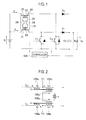
- FIG. 1 is a circuit diagram illustrating a DC-DC converter according to a related art.
- Figure 2 is an equivalent circuit diagram illustrating a coupling transformer 20 in the DC-DC converter of the related art illustrated in Fig. 1 .
- the DC-DC converter illustrated in Fig. 1 has a DC power source Vi, the coupling transformer 20, switches Tr1 and Tr2, diodes D1 and D2, a smoothing capacitor Co, a load resistance Ro, and a controller 100.
- the coupling transformer 20 has, as illustrated in Fig. 2 , a transformer T3, a transformer T4, and a reactor L3.
- the transformer T3 has a primary winding 105a (having the number of turns of np), a coiled winding 105b (having the number of turns of np1) connected in series with the primary winding 105a, and a secondary winding 105c (having the number of turns of ns) electromagnetically coupled with the primary winding 105a and coiled winding 105b.
- the transformer T4 is configured same as the transformer T3 and has a primary winding 106a (having the number of turns of np), a coiled winding 106b (having the number of turns of np1) connected in series with the primary winding 106a, and a secondary winding 106c (having the number of turns of ns) electromagnetically coupled with the primary winding 106a and coiled winding 106b.
- Both ends of the DC power source Vi are connected through the primary winding 105a of the transformer T3 to the collector and emitter of the switch Tr1 of an IGBT (Insulated Gate Bipolar Transistor).
- the both ends of the DC power source Vi are connected through the primary winding 106a of the transformer T4 to the collector and emitter of the switch Tr2 made of an IGBT.
- a connection point between the primary winding 105a of the transformer T3 and the collector of the switch Tr1, as well as the emitter of the switch Tr1 are connected to a series circuit that includes the coiled winding 105b of the transformer T3, the diode D1, and the smoothing capacitor Co.
- a connection point between the primary winding 106a of the transformer T4 and the collector of the switch Tr2, as well as the emitter of the switch Tr2 are connected to a series circuit that includes the coiled winding 106b of the transformer T4, the diode D2, and the smoothing capacitor Co.
- Both ends of a series circuit that includes the secondary winding 105c of the transformer T3 and the secondary winding 106c of the transformer T4 are connected to the reactor L3.
- the controller 100 controls according to an output voltage Vo of the smoothing capacitor Co so that the switch Tr2 turns on after the switch Tr1 turns on and before the switch Tr1 turns off and so that the switch Tr1 turns on before the switch Tr2 turns off. Namely, it alternately turns on the switches Tr1 and Tr2 and makes the switches Tr1 and Tr2 simultaneously ON for a predetermined overlapping period on every half cycle.
- the controller 100 issues a control signal Tr1g to turn on the switch Tr1, and after the predetermined overlapping period, issues a control signal Tr2g to turn off the switch Tr2, so that a current passes through a path extending along Vi (plus (+) side), 105a, Tr1, and Vi (minus (-) side) to linearly increase the current of the switch Tr1.
- the secondary winding 105c of the transformer T3 generates a voltage to pass a current L3i clockwise through a path extending along 105c, L3, 106c, and 105c.
- the current L3i causes according to the law of equal ampere-turns of the transformer, to accumulate energy in the reactor L3 and the same current passes through the secondary winding 106c of the transformer T4.
- the primary winding 106a and coiled winding 106b of the transformer T4 induce voltages depending on the numbers of turns thereof.
- a current of "1 / A" of the current to the switch Tr1 passes to the diode D2 through a route extending along Vi+, 106a, 106b, D2, Co, and Vi-.
- the current passes through the diode D2 until the switch Tr2 turns on.
- the output voltage Vo of the smoothing capacitor Co is the sum of a voltage generated by the primary winding 106a of the transformer T4 and a voltage generated by the coiled winding 106b of the transformer T4.
- the controller 100 issues a control signal Tr2g to turn on the switch Tr2, and after the predetermined overlapping period, issues a control signal Tr1g to turn off the switch Tr1.
- Tr2g to turn on the switch Tr2
- Tr1g to turn off the switch Tr1.
- the controller 100 issues a control signal Tr2g to turn on the switch Tr2
- Tr1g issues a control signal to turn off the switch Tr1.
- the secondary winding 106c of the transformer T4 generates a voltage to increase and pass the current L3i clockwise through a path extending along 106c, 105c, L3, and 106c.
- the current L3i causes according to the law of equal ampere-turns of the transformer, to accumulate energy in the reactor L3 and the same current passes through the secondary winding 105c of the transformer T3.
- the primary winding 105a and coiled winding 105b of the transformer T3 induce voltages depending on the numbers of turns thereof.
- the output voltage Vo of the smoothing capacitor Co is the sum of a voltage (an input voltage) of the DC power source Vi, a voltage generated by the primary winding 105a of the transformer T3, and a voltage generated by the coiled winding 105b of the transformer T3.
- the DC-DC converter of the related art illustrated in Fig. 1 is known as a multiphase transformer-linked step-up chopper circuit whose example is disclosed in Japanese Unexamined Patent Application Publication No. 2010-004704 (Patent Literature 1) (refer to Patent Literature 1).
- the DC-DC converter connects two independent phases to each other through a transformer. This reduces the number of required cores from two to one to carry out a step-up operation.
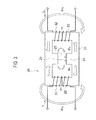
- the coupling transformer 20 has a core 21 that is a combination of two E-shaped core members faced in an extending planar direction.
- the core 21 has side legs 22 and 23, a center leg 24, and a gap 25.
- a winding 31 is wound, and around the side leg 23, a winding 32 is wound.
- a current i1 passes through the winding 31 and a current i2 the winding 32.
- the coupling transformer 20 leaks a magnetic flux component ⁇ 1k ( ⁇ is a Greek letter "phi") outside the windings 31 and 32 as illustrated in Fig. 3 . Also, the gap 25 of the core 21 leaks a magnetic flux component ⁇ fr due to a fringing effect. Namely, the coupling transformer 20 of the related art causes large leakage flux to enlarge differences from theoretical values.
- the present invention is able to provide a DC-DC converter having a coupling transformer that substantially realizes a design based on theoretical values.
- the DC-DC converter includes a coupling transformer having a first winding and a second winding, a first switch connected through the first winding to both ends of a DC power source, a second switch connected through the second winding to the both ends of the DC power source, a first series circuit connected to both ends of the first switch and including a first diode and a smoothing capacitor, a second series circuit connected to both ends of the second switch and including a second diode and the smoothing capacitor, and a controller that alternately turns on the first and second switches and simultaneously turns on the first and second switches for a predetermined overlapping period on every half cycle.
- the coupling transformer has an I-shaped core, two E-shaped cores holding the I-shaped core between them, a first gap formed between a center leg of one of the E-shaped cores and the I-shaped core, a second gap formed between a center leg of the other E-shaped core and the I-shaped core, and the first and second windings wound around the I-shaped core.
- the DC-DC converters of the present invention are characterized in that each employs two E-shaped cores and an I-shaped core to realize a coupling transformer that reduces leakage flux and substantially realizes a design based on theoretical values.
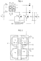
- Figure 4 is a circuit diagram illustrating a DC-DC converter according to Embodiment 1.
- Figure 5 is a schematic view illustrating a coupling transformer that employs an EEI core and is incorporated in the DC-DC converter of Embodiment 1. The embodiment is characterized in that it employs, instead of the coupling transformer 20 of the related art illustrated in Figs. 1 to 3 , the coupling transformer 1 illustrated in Fig. 5 .
- Fig. 4 The remaining configuration of Fig. 4 is the same as that of Fig. 1 , and therefore, like parts are represented with like reference marks to omit the detailed explanations thereof. Only the coupling transformer 1 will be explained here.
- the coupling transformer 1 illustrated in Fig. 5 has an I-shaped core 4 and two E-shaped cores 2 and 3 that hold the I-shaped core 4 between them.
- the two E-shaped cores 2 and 3 are integrated into one so that center legs 2a and 3a thereof face each other in an extending planar direction with the I-shaped core 4 interposed between them. More precisely, a first gap 5 is formed between the center leg 2a of the E-shaped core 2 and the I-shaped core 4 and a second gap 5 is formed between the center leg 3a of the E-shaped core 3 and the I-shaped core 4.
- a winding 11 (a first winding) having the number of turns of n1 and a winding 12 (a second winding) having the number of turns of n2 are wound.
- a current i1 passes through the winding 11 and a current i2 passes through the winding 12.
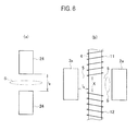
- Figure 6 is a comparative view illustrating a gap length of the related art and that of Embodiment 1, in which Fig. 6 (a) is of the related art and Fig. 6(b) of Embodiment 1.
- the current i1 passes through the winding 11 and the current i2 passes through the winding 12.
- the currents passing through the windings 11 and 12 generate magnetic flux along magnetic paths starting from the I-shaped core 4, passing through the gaps 5 and E-shaped cores 2 and 3, and returning to the I-shaped core 4. Closed magnetic paths are formed to greatly reduce leakage magnetic flux and shorten a gap length.
- the embodiment is able to provide a DC-DC converter having the coupling transformer that is capable of substantially realizing a design based on theoretical values.
- the coupling transformer 20 of the related art illustrated in Fig. 3 winds the windings 31 and 32 around the side legs 22 and 23, and therefore, magnetic flux leaks outside the side legs 22 and 23. This results in increasing leakage magnetic flux and expanding a difference between an actually measured value and a theoretical value.
- Figure 7 is a comparative view illustrating a winding method of the coupling transformer according to the related art and that according to Embodiment 2, in which Fig. 7(a) is a schematic view of the coupling transformer 20 according to the related art and Fig. 7(b) is of a coupling transformer according to Embodiment 2.
- the DC-DC converter of Embodiment 2 is the same as that illustrated in Fig. 4 .
- the winding 31 having the number of turns of n1 is wound around the side leg 22 and the winding 32 having the number of turns of n2 is wound around the side leg 23.
- the coupling transformer of the embodiment illustrated in Fig. 7(b) connects, between a positive electrode of a DC power source Vi and the collector of a switch Tr1, a series circuit in which a winding 31a (a first winding) is connected in series with a winding 31b (a second winding).
- a winding 32a (a third winding) is connected in series with a winding 32b (a fourth winding) and this series circuit is connected between the positive electrode of the DC power source Vi and the collector of a switch Tr2.
- the coupling transformer has two E-shaped cores that are integrated into a ⁇ -shape with respective center legs 24a being faced to each other in an extending planar direction.
- a gap 25a is formed between the center leg 24a of one of the E-shaped cores and the center leg 24a of the other E-shaped core.
- the windings 31a and 32b are wound, and around side legs 23 of the E-shaped cores, the windings 31b and 32a are wound.
- the sum of the numbers of turns of the windings 31a and 31b is n1 and the sum of the numbers of turns of the windings 32a and 32b is n2.
- windings 31 and 32 are each divided into two and the windings 31a and 32b are wound around the side legs 22 and the windings 31b and 32a around the side legs 23.
- magnetomotive force is distributed and a gap length is shortened, thereby the degree of coupling is improved.
- the present invention is able to provide a DC-DC converter having the coupling transformer that is capable of reducing leakage magnetic flux and substantially realizing a design based on theoretical values.
Landscapes
- Engineering & Computer Science (AREA)
- Power Engineering (AREA)
- Chemical & Material Sciences (AREA)
- Composite Materials (AREA)
- Dc-Dc Converters (AREA)
- Coils Or Transformers For Communication (AREA)
Applications Claiming Priority (2)
| Application Number | Priority Date | Filing Date | Title |
|---|---|---|---|
| JP2012060547A JP5934001B2 (ja) | 2012-03-16 | 2012-03-16 | Dc−dcコンバータ |
| PCT/JP2013/051475 WO2013136854A1 (ja) | 2012-03-16 | 2013-01-24 | Dc-dcコンバータ |
Publications (3)
| Publication Number | Publication Date |
|---|---|
| EP2827484A1 true EP2827484A1 (de) | 2015-01-21 |
| EP2827484A4 EP2827484A4 (de) | 2015-03-18 |
| EP2827484B1 EP2827484B1 (de) | 2019-10-16 |
Family
ID=49160776
Family Applications (1)
| Application Number | Title | Priority Date | Filing Date |
|---|---|---|---|
| EP13761993.8A Active EP2827484B1 (de) | 2012-03-16 | 2013-01-24 | Gleichspannungswandler |
Country Status (6)
| Country | Link |
|---|---|
| US (1) | US20150070942A1 (de) |
| EP (1) | EP2827484B1 (de) |
| JP (1) | JP5934001B2 (de) |
| KR (1) | KR101631697B1 (de) |
| CN (1) | CN104247237B (de) |
| WO (1) | WO2013136854A1 (de) |
Cited By (1)
| Publication number | Priority date | Publication date | Assignee | Title |
|---|---|---|---|---|
| US20220223335A1 (en) * | 2021-01-11 | 2022-07-14 | Delta Electronics, Inc. | Transformer |
Families Citing this family (8)
| Publication number | Priority date | Publication date | Assignee | Title |
|---|---|---|---|---|
| JP3094420B2 (ja) | 1990-02-20 | 2000-10-03 | 日本電気株式会社 | 平面アンテナ |
| JP2997451B1 (ja) | 1998-07-30 | 2000-01-11 | 日本アンテナ株式会社 | 小型アンテナ |
| JP6578093B2 (ja) * | 2014-09-25 | 2019-09-18 | 本田技研工業株式会社 | 磁気結合型リアクトル |
| EP3157022A1 (de) * | 2015-10-16 | 2017-04-19 | SMA Solar Technology AG | Drosselanordnung und energieversorgungssystem unter verwendung derselben |
| US11245333B2 (en) * | 2016-03-04 | 2022-02-08 | Mitsubishi Electric Corporation | Power conversion device |
| WO2019082489A1 (ja) | 2017-10-25 | 2019-05-02 | 住友電気工業株式会社 | コイル部品、回路基板、及び電源装置 |
| JP7145228B2 (ja) * | 2018-11-02 | 2022-09-30 | 本田技研工業株式会社 | リアクトル及び複数相インターリーブ型のdc-dcコンバータ |
| JP2020103009A (ja) * | 2018-12-25 | 2020-07-02 | トヨタ自動車株式会社 | 電力変換器及びモータシステム |
Family Cites Families (19)
| Publication number | Priority date | Publication date | Assignee | Title |
|---|---|---|---|---|
| US3896407A (en) * | 1974-10-07 | 1975-07-22 | Esquire Inc | Magnetic core and coil device |
| JPS5881921U (ja) * | 1981-11-25 | 1983-06-03 | 松下電工株式会社 | 電磁装置 |
| JP2668545B2 (ja) * | 1988-04-26 | 1997-10-27 | 株式会社キジマ | 電気巻線部品 |
| JPH05109549A (ja) * | 1991-10-20 | 1993-04-30 | Eye Lighting Syst Corp | 放電灯安定器用鉄心 |
| DE19934767A1 (de) * | 1999-07-23 | 2001-01-25 | Philips Corp Intellectual Pty | Magnetisches Bauelement |
| JP2005223125A (ja) * | 2004-02-05 | 2005-08-18 | Murata Mfg Co Ltd | 昇圧トランス |
| JP4496556B2 (ja) * | 2004-11-24 | 2010-07-07 | 株式会社キジマ | 小形トランス |
| JP4434048B2 (ja) * | 2005-03-16 | 2010-03-17 | サンケン電気株式会社 | Dc/dcコンバータ |
| JP2008205466A (ja) * | 2007-02-17 | 2008-09-04 | Zhejiang Univ | 磁気部品 |
| CN101308724B (zh) * | 2007-02-17 | 2010-04-14 | 浙江大学 | 变压器和电感的磁集成结构 |
| JP2010004704A (ja) * | 2008-06-23 | 2010-01-07 | Sanken Electric Co Ltd | Dc−dcコンバータ |
| US8111053B2 (en) * | 2008-07-24 | 2012-02-07 | Sanken Electric Co., Ltd. | DC-DC converter |
| US8975884B2 (en) * | 2009-03-27 | 2015-03-10 | GM Global Technology Operations LLC | Two-phase transformer-coupled boost converter |
| JP2011130573A (ja) * | 2009-12-17 | 2011-06-30 | Nippon Soken Inc | Dcdcコンバータ |
| JP2011130572A (ja) * | 2009-12-17 | 2011-06-30 | Nippon Soken Inc | Dcdcコンバータ |
| JP5129294B2 (ja) * | 2010-04-28 | 2013-01-30 | 新東ホールディングス株式会社 | 電力変換装置 |
| US8610533B2 (en) * | 2011-03-31 | 2013-12-17 | Bose Corporation | Power converter using soft composite magnetic structure |
| EP2565883A1 (de) * | 2011-09-02 | 2013-03-06 | University College Cork | Transformator mit geteilter Wicklung |
| US9379629B2 (en) * | 2012-07-16 | 2016-06-28 | Power Systems Technologies, Ltd. | Magnetic device and power converter employing the same |
-
2012
- 2012-03-16 JP JP2012060547A patent/JP5934001B2/ja not_active Expired - Fee Related
-
2013
- 2013-01-24 CN CN201380014602.6A patent/CN104247237B/zh not_active Expired - Fee Related
- 2013-01-24 KR KR1020147028908A patent/KR101631697B1/ko not_active Expired - Fee Related
- 2013-01-24 WO PCT/JP2013/051475 patent/WO2013136854A1/ja not_active Ceased
- 2013-01-24 US US14/385,322 patent/US20150070942A1/en not_active Abandoned
- 2013-01-24 EP EP13761993.8A patent/EP2827484B1/de active Active
Cited By (2)
| Publication number | Priority date | Publication date | Assignee | Title |
|---|---|---|---|---|
| US20220223335A1 (en) * | 2021-01-11 | 2022-07-14 | Delta Electronics, Inc. | Transformer |
| US12462972B2 (en) * | 2021-01-11 | 2025-11-04 | Delta Electronics, Inc. | Transformer |
Also Published As
| Publication number | Publication date |
|---|---|
| KR20140136502A (ko) | 2014-11-28 |
| US20150070942A1 (en) | 2015-03-12 |
| CN104247237B (zh) | 2017-10-03 |
| JP5934001B2 (ja) | 2016-06-15 |
| JP2013198211A (ja) | 2013-09-30 |
| WO2013136854A1 (ja) | 2013-09-19 |
| KR101631697B1 (ko) | 2016-06-20 |
| EP2827484A4 (de) | 2015-03-18 |
| CN104247237A (zh) | 2014-12-24 |
| EP2827484B1 (de) | 2019-10-16 |
Similar Documents
| Publication | Publication Date | Title |
|---|---|---|
| EP2827484A1 (de) | Gleichspannungswandler | |
| US10630191B2 (en) | Transformer and LLC resonant converter having the same | |
| RU2524385C2 (ru) | Магнитный интегральный симметричный конвертер | |
| US9019061B2 (en) | Magnetic device formed with U-shaped core pieces and power converter employing the same | |
| US10211745B2 (en) | Resonant LLC converter with a multi-leg transformer with gapped center leg | |
| US10985649B2 (en) | Power conversion device with in-phase and interleave driving based on determination of duty ratio | |
| US10505459B2 (en) | Power conversion device | |
| US20060208713A1 (en) | DC/DC converter | |
| JP4175367B2 (ja) | スイッチング電源装置 | |
| JP3693061B1 (ja) | スイッチング電源装置 | |
| US8111053B2 (en) | DC-DC converter | |
| JP5892172B2 (ja) | インバータ装置 | |
| KR101229265B1 (ko) | 집적 변압기 및 이를 이용한 고승압 직류-직류 컨버터 | |
| JP4151016B2 (ja) | 絶縁型スイッチングdc/dcコンバータ | |
| JP4151015B2 (ja) | 絶縁型スイッチングdc/dcコンバータ | |
| JP2020022307A (ja) | 電源装置及び電源装置の制御方法 | |
| JP2020137320A (ja) | 降圧コンバータ | |
| JP2016119754A (ja) | 電力変換装置 |
Legal Events
| Date | Code | Title | Description |
|---|---|---|---|
| PUAI | Public reference made under article 153(3) epc to a published international application that has entered the european phase |
Free format text: ORIGINAL CODE: 0009012 |
|
| 17P | Request for examination filed |
Effective date: 20141016 |
|
| AK | Designated contracting states |
Kind code of ref document: A1 Designated state(s): AL AT BE BG CH CY CZ DE DK EE ES FI FR GB GR HR HU IE IS IT LI LT LU LV MC MK MT NL NO PL PT RO RS SE SI SK SM TR |
|
| AX | Request for extension of the european patent |
Extension state: BA ME |
|
| A4 | Supplementary search report drawn up and despatched |
Effective date: 20150218 |
|
| RIC1 | Information provided on ipc code assigned before grant |
Ipc: H01F 30/00 20060101ALI20150212BHEP Ipc: H01F 3/14 20060101ALI20150212BHEP Ipc: H02M 3/158 20060101AFI20150212BHEP |
|
| DAX | Request for extension of the european patent (deleted) | ||
| 17Q | First examination report despatched |
Effective date: 20161010 |
|
| STAA | Information on the status of an ep patent application or granted ep patent |
Free format text: STATUS: EXAMINATION IS IN PROGRESS |
|
| RAP1 | Party data changed (applicant data changed or rights of an application transferred) |
Owner name: SANKEN ELECTRIC CO., LTD. Owner name: NATIONAL UNIVERSITY CORPORATION NAGOYA UNIVERSITY |
|
| GRAP | Despatch of communication of intention to grant a patent |
Free format text: ORIGINAL CODE: EPIDOSNIGR1 |
|
| STAA | Information on the status of an ep patent application or granted ep patent |
Free format text: STATUS: GRANT OF PATENT IS INTENDED |
|
| INTG | Intention to grant announced |
Effective date: 20190603 |
|
| GRAS | Grant fee paid |
Free format text: ORIGINAL CODE: EPIDOSNIGR3 |
|
| GRAA | (expected) grant |
Free format text: ORIGINAL CODE: 0009210 |
|
| STAA | Information on the status of an ep patent application or granted ep patent |
Free format text: STATUS: THE PATENT HAS BEEN GRANTED |
|
| AK | Designated contracting states |
Kind code of ref document: B1 Designated state(s): AL AT BE BG CH CY CZ DE DK EE ES FI FR GB GR HR HU IE IS IT LI LT LU LV MC MK MT NL NO PL PT RO RS SE SI SK SM TR |
|
| REG | Reference to a national code |
Ref country code: GB Ref legal event code: FG4D |
|
| REG | Reference to a national code |
Ref country code: CH Ref legal event code: EP |
|
| REG | Reference to a national code |
Ref country code: DE Ref legal event code: R096 Ref document number: 602013061786 Country of ref document: DE |
|
| REG | Reference to a national code |
Ref country code: IE Ref legal event code: FG4D |
|
| REG | Reference to a national code |
Ref country code: AT Ref legal event code: REF Ref document number: 1192265 Country of ref document: AT Kind code of ref document: T Effective date: 20191115 |
|
| REG | Reference to a national code |
Ref country code: NL Ref legal event code: MP Effective date: 20191016 |
|
| REG | Reference to a national code |
Ref country code: LT Ref legal event code: MG4D |
|
| REG | Reference to a national code |
Ref country code: AT Ref legal event code: MK05 Ref document number: 1192265 Country of ref document: AT Kind code of ref document: T Effective date: 20191016 |
|
| PG25 | Lapsed in a contracting state [announced via postgrant information from national office to epo] |
Ref country code: AT Free format text: LAPSE BECAUSE OF FAILURE TO SUBMIT A TRANSLATION OF THE DESCRIPTION OR TO PAY THE FEE WITHIN THE PRESCRIBED TIME-LIMIT Effective date: 20191016 Ref country code: ES Free format text: LAPSE BECAUSE OF FAILURE TO SUBMIT A TRANSLATION OF THE DESCRIPTION OR TO PAY THE FEE WITHIN THE PRESCRIBED TIME-LIMIT Effective date: 20191016 Ref country code: NL Free format text: LAPSE BECAUSE OF FAILURE TO SUBMIT A TRANSLATION OF THE DESCRIPTION OR TO PAY THE FEE WITHIN THE PRESCRIBED TIME-LIMIT Effective date: 20191016 Ref country code: LV Free format text: LAPSE BECAUSE OF FAILURE TO SUBMIT A TRANSLATION OF THE DESCRIPTION OR TO PAY THE FEE WITHIN THE PRESCRIBED TIME-LIMIT Effective date: 20191016 Ref country code: SE Free format text: LAPSE BECAUSE OF FAILURE TO SUBMIT A TRANSLATION OF THE DESCRIPTION OR TO PAY THE FEE WITHIN THE PRESCRIBED TIME-LIMIT Effective date: 20191016 Ref country code: NO Free format text: LAPSE BECAUSE OF FAILURE TO SUBMIT A TRANSLATION OF THE DESCRIPTION OR TO PAY THE FEE WITHIN THE PRESCRIBED TIME-LIMIT Effective date: 20200116 Ref country code: GR Free format text: LAPSE BECAUSE OF FAILURE TO SUBMIT A TRANSLATION OF THE DESCRIPTION OR TO PAY THE FEE WITHIN THE PRESCRIBED TIME-LIMIT Effective date: 20200117 Ref country code: PL Free format text: LAPSE BECAUSE OF FAILURE TO SUBMIT A TRANSLATION OF THE DESCRIPTION OR TO PAY THE FEE WITHIN THE PRESCRIBED TIME-LIMIT Effective date: 20191016 Ref country code: LT Free format text: LAPSE BECAUSE OF FAILURE TO SUBMIT A TRANSLATION OF THE DESCRIPTION OR TO PAY THE FEE WITHIN THE PRESCRIBED TIME-LIMIT Effective date: 20191016 Ref country code: PT Free format text: LAPSE BECAUSE OF FAILURE TO SUBMIT A TRANSLATION OF THE DESCRIPTION OR TO PAY THE FEE WITHIN THE PRESCRIBED TIME-LIMIT Effective date: 20200217 Ref country code: BG Free format text: LAPSE BECAUSE OF FAILURE TO SUBMIT A TRANSLATION OF THE DESCRIPTION OR TO PAY THE FEE WITHIN THE PRESCRIBED TIME-LIMIT Effective date: 20200116 Ref country code: FI Free format text: LAPSE BECAUSE OF FAILURE TO SUBMIT A TRANSLATION OF THE DESCRIPTION OR TO PAY THE FEE WITHIN THE PRESCRIBED TIME-LIMIT Effective date: 20191016 |
|
| PGFP | Annual fee paid to national office [announced via postgrant information from national office to epo] |
Ref country code: DE Payment date: 20200127 Year of fee payment: 8 |
|
| PG25 | Lapsed in a contracting state [announced via postgrant information from national office to epo] |
Ref country code: HR Free format text: LAPSE BECAUSE OF FAILURE TO SUBMIT A TRANSLATION OF THE DESCRIPTION OR TO PAY THE FEE WITHIN THE PRESCRIBED TIME-LIMIT Effective date: 20191016 Ref country code: RS Free format text: LAPSE BECAUSE OF FAILURE TO SUBMIT A TRANSLATION OF THE DESCRIPTION OR TO PAY THE FEE WITHIN THE PRESCRIBED TIME-LIMIT Effective date: 20191016 Ref country code: IS Free format text: LAPSE BECAUSE OF FAILURE TO SUBMIT A TRANSLATION OF THE DESCRIPTION OR TO PAY THE FEE WITHIN THE PRESCRIBED TIME-LIMIT Effective date: 20200224 |
|
| PG25 | Lapsed in a contracting state [announced via postgrant information from national office to epo] |
Ref country code: AL Free format text: LAPSE BECAUSE OF FAILURE TO SUBMIT A TRANSLATION OF THE DESCRIPTION OR TO PAY THE FEE WITHIN THE PRESCRIBED TIME-LIMIT Effective date: 20191016 |
|
| PGFP | Annual fee paid to national office [announced via postgrant information from national office to epo] |
Ref country code: FR Payment date: 20200128 Year of fee payment: 8 |
|
| REG | Reference to a national code |
Ref country code: DE Ref legal event code: R097 Ref document number: 602013061786 Country of ref document: DE |
|
| PG2D | Information on lapse in contracting state deleted |
Ref country code: IS |
|
| PG25 | Lapsed in a contracting state [announced via postgrant information from national office to epo] |
Ref country code: IS Free format text: LAPSE BECAUSE OF FAILURE TO SUBMIT A TRANSLATION OF THE DESCRIPTION OR TO PAY THE FEE WITHIN THE PRESCRIBED TIME-LIMIT Effective date: 20200216 Ref country code: CZ Free format text: LAPSE BECAUSE OF FAILURE TO SUBMIT A TRANSLATION OF THE DESCRIPTION OR TO PAY THE FEE WITHIN THE PRESCRIBED TIME-LIMIT Effective date: 20191016 Ref country code: RO Free format text: LAPSE BECAUSE OF FAILURE TO SUBMIT A TRANSLATION OF THE DESCRIPTION OR TO PAY THE FEE WITHIN THE PRESCRIBED TIME-LIMIT Effective date: 20191016 Ref country code: DK Free format text: LAPSE BECAUSE OF FAILURE TO SUBMIT A TRANSLATION OF THE DESCRIPTION OR TO PAY THE FEE WITHIN THE PRESCRIBED TIME-LIMIT Effective date: 20191016 Ref country code: EE Free format text: LAPSE BECAUSE OF FAILURE TO SUBMIT A TRANSLATION OF THE DESCRIPTION OR TO PAY THE FEE WITHIN THE PRESCRIBED TIME-LIMIT Effective date: 20191016 |
|
| PLBE | No opposition filed within time limit |
Free format text: ORIGINAL CODE: 0009261 |
|
| STAA | Information on the status of an ep patent application or granted ep patent |
Free format text: STATUS: NO OPPOSITION FILED WITHIN TIME LIMIT |
|
| PG25 | Lapsed in a contracting state [announced via postgrant information from national office to epo] |
Ref country code: SK Free format text: LAPSE BECAUSE OF FAILURE TO SUBMIT A TRANSLATION OF THE DESCRIPTION OR TO PAY THE FEE WITHIN THE PRESCRIBED TIME-LIMIT Effective date: 20191016 Ref country code: IT Free format text: LAPSE BECAUSE OF FAILURE TO SUBMIT A TRANSLATION OF THE DESCRIPTION OR TO PAY THE FEE WITHIN THE PRESCRIBED TIME-LIMIT Effective date: 20191016 Ref country code: SM Free format text: LAPSE BECAUSE OF FAILURE TO SUBMIT A TRANSLATION OF THE DESCRIPTION OR TO PAY THE FEE WITHIN THE PRESCRIBED TIME-LIMIT Effective date: 20191016 Ref country code: MC Free format text: LAPSE BECAUSE OF FAILURE TO SUBMIT A TRANSLATION OF THE DESCRIPTION OR TO PAY THE FEE WITHIN THE PRESCRIBED TIME-LIMIT Effective date: 20191016 |
|
| REG | Reference to a national code |
Ref country code: CH Ref legal event code: PL |
|
| 26N | No opposition filed |
Effective date: 20200717 |
|
| GBPC | Gb: european patent ceased through non-payment of renewal fee |
Effective date: 20200124 |
|
| REG | Reference to a national code |
Ref country code: BE Ref legal event code: MM Effective date: 20200131 |
|
| PG25 | Lapsed in a contracting state [announced via postgrant information from national office to epo] |
Ref country code: LU Free format text: LAPSE BECAUSE OF NON-PAYMENT OF DUE FEES Effective date: 20200124 Ref country code: GB Free format text: LAPSE BECAUSE OF NON-PAYMENT OF DUE FEES Effective date: 20200124 |
|
| PG25 | Lapsed in a contracting state [announced via postgrant information from national office to epo] |
Ref country code: BE Free format text: LAPSE BECAUSE OF NON-PAYMENT OF DUE FEES Effective date: 20200131 Ref country code: SI Free format text: LAPSE BECAUSE OF FAILURE TO SUBMIT A TRANSLATION OF THE DESCRIPTION OR TO PAY THE FEE WITHIN THE PRESCRIBED TIME-LIMIT Effective date: 20191016 Ref country code: LI Free format text: LAPSE BECAUSE OF NON-PAYMENT OF DUE FEES Effective date: 20200131 Ref country code: CH Free format text: LAPSE BECAUSE OF NON-PAYMENT OF DUE FEES Effective date: 20200131 |
|
| PG25 | Lapsed in a contracting state [announced via postgrant information from national office to epo] |
Ref country code: IE Free format text: LAPSE BECAUSE OF NON-PAYMENT OF DUE FEES Effective date: 20200124 |
|
| REG | Reference to a national code |
Ref country code: DE Ref legal event code: R119 Ref document number: 602013061786 Country of ref document: DE |
|
| PG25 | Lapsed in a contracting state [announced via postgrant information from national office to epo] |
Ref country code: FR Free format text: LAPSE BECAUSE OF NON-PAYMENT OF DUE FEES Effective date: 20210131 |
|
| PG25 | Lapsed in a contracting state [announced via postgrant information from national office to epo] |
Ref country code: DE Free format text: LAPSE BECAUSE OF NON-PAYMENT OF DUE FEES Effective date: 20210803 |
|
| PG25 | Lapsed in a contracting state [announced via postgrant information from national office to epo] |
Ref country code: TR Free format text: LAPSE BECAUSE OF FAILURE TO SUBMIT A TRANSLATION OF THE DESCRIPTION OR TO PAY THE FEE WITHIN THE PRESCRIBED TIME-LIMIT Effective date: 20191016 Ref country code: MT Free format text: LAPSE BECAUSE OF FAILURE TO SUBMIT A TRANSLATION OF THE DESCRIPTION OR TO PAY THE FEE WITHIN THE PRESCRIBED TIME-LIMIT Effective date: 20191016 Ref country code: CY Free format text: LAPSE BECAUSE OF FAILURE TO SUBMIT A TRANSLATION OF THE DESCRIPTION OR TO PAY THE FEE WITHIN THE PRESCRIBED TIME-LIMIT Effective date: 20191016 |
|
| PG25 | Lapsed in a contracting state [announced via postgrant information from national office to epo] |
Ref country code: MK Free format text: LAPSE BECAUSE OF FAILURE TO SUBMIT A TRANSLATION OF THE DESCRIPTION OR TO PAY THE FEE WITHIN THE PRESCRIBED TIME-LIMIT Effective date: 20191016 |