EP2810778B1 - Verfahren zum Herstellen einer Siebstruktur - Google Patents
Verfahren zum Herstellen einer Siebstruktur Download PDFInfo
- Publication number
- EP2810778B1 EP2810778B1 EP14169388.7A EP14169388A EP2810778B1 EP 2810778 B1 EP2810778 B1 EP 2810778B1 EP 14169388 A EP14169388 A EP 14169388A EP 2810778 B1 EP2810778 B1 EP 2810778B1
- Authority
- EP
- European Patent Office
- Prior art keywords
- mesh
- screen structure
- fabric
- layer
- screen
- Prior art date
- Legal status (The legal status is an assumption and is not a legal conclusion. Google has not performed a legal analysis and makes no representation as to the accuracy of the status listed.)
- Active
Links
Images


Classifications
-
- B—PERFORMING OPERATIONS; TRANSPORTING
- B41—PRINTING; LINING MACHINES; TYPEWRITERS; STAMPS
- B41C—PROCESSES FOR THE MANUFACTURE OR REPRODUCTION OF PRINTING SURFACES
- B41C1/00—Forme preparation
- B41C1/14—Forme preparation for stencil-printing or silk-screen printing
-
- B—PERFORMING OPERATIONS; TRANSPORTING
- B32—LAYERED PRODUCTS
- B32B—LAYERED PRODUCTS, i.e. PRODUCTS BUILT-UP OF STRATA OF FLAT OR NON-FLAT, e.g. CELLULAR OR HONEYCOMB, FORM
- B32B5/00—Layered products characterised by the non- homogeneity or physical structure, i.e. comprising a fibrous, filamentary, particulate or foam layer; Layered products characterised by having a layer differing constitutionally or physically in different parts
- B32B5/02—Layered products characterised by the non- homogeneity or physical structure, i.e. comprising a fibrous, filamentary, particulate or foam layer; Layered products characterised by having a layer differing constitutionally or physically in different parts characterised by structural features of a fibrous or filamentary layer
- B32B5/028—Net structure, e.g. spaced apart filaments bonded at the crossing points
-
- B—PERFORMING OPERATIONS; TRANSPORTING
- B32—LAYERED PRODUCTS
- B32B—LAYERED PRODUCTS, i.e. PRODUCTS BUILT-UP OF STRATA OF FLAT OR NON-FLAT, e.g. CELLULAR OR HONEYCOMB, FORM
- B32B5/00—Layered products characterised by the non- homogeneity or physical structure, i.e. comprising a fibrous, filamentary, particulate or foam layer; Layered products characterised by having a layer differing constitutionally or physically in different parts
- B32B5/22—Layered products characterised by the non- homogeneity or physical structure, i.e. comprising a fibrous, filamentary, particulate or foam layer; Layered products characterised by having a layer differing constitutionally or physically in different parts characterised by the presence of two or more layers which are next to each other and are fibrous, filamentary, formed of particles or foamed
- B32B5/24—Layered products characterised by the non- homogeneity or physical structure, i.e. comprising a fibrous, filamentary, particulate or foam layer; Layered products characterised by having a layer differing constitutionally or physically in different parts characterised by the presence of two or more layers which are next to each other and are fibrous, filamentary, formed of particles or foamed one layer being a fibrous or filamentary layer
- B32B5/26—Layered products characterised by the non- homogeneity or physical structure, i.e. comprising a fibrous, filamentary, particulate or foam layer; Layered products characterised by having a layer differing constitutionally or physically in different parts characterised by the presence of two or more layers which are next to each other and are fibrous, filamentary, formed of particles or foamed one layer being a fibrous or filamentary layer another layer next to it also being fibrous or filamentary
-
- B—PERFORMING OPERATIONS; TRANSPORTING
- B41—PRINTING; LINING MACHINES; TYPEWRITERS; STAMPS
- B41C—PROCESSES FOR THE MANUFACTURE OR REPRODUCTION OF PRINTING SURFACES
- B41C1/00—Forme preparation
- B41C1/14—Forme preparation for stencil-printing or silk-screen printing
- B41C1/142—Forme preparation for stencil-printing or silk-screen printing using a galvanic or electroless metal deposition processing step
-
- B—PERFORMING OPERATIONS; TRANSPORTING
- B41—PRINTING; LINING MACHINES; TYPEWRITERS; STAMPS
- B41N—PRINTING PLATES OR FOILS; MATERIALS FOR SURFACES USED IN PRINTING MACHINES FOR PRINTING, INKING, DAMPING, OR THE LIKE; PREPARING SUCH SURFACES FOR USE AND CONSERVING THEM
- B41N1/00—Printing plates or foils; Materials therefor
- B41N1/24—Stencils; Stencil materials; Carriers therefor
- B41N1/247—Meshes, gauzes, woven or similar screen materials; Preparation thereof, e.g. by plasma treatment
-
- B—PERFORMING OPERATIONS; TRANSPORTING
- B32—LAYERED PRODUCTS
- B32B—LAYERED PRODUCTS, i.e. PRODUCTS BUILT-UP OF STRATA OF FLAT OR NON-FLAT, e.g. CELLULAR OR HONEYCOMB, FORM
- B32B2255/00—Coating on the layer surface
- B32B2255/02—Coating on the layer surface on fibrous or filamentary layer
-
- B—PERFORMING OPERATIONS; TRANSPORTING
- B32—LAYERED PRODUCTS
- B32B—LAYERED PRODUCTS, i.e. PRODUCTS BUILT-UP OF STRATA OF FLAT OR NON-FLAT, e.g. CELLULAR OR HONEYCOMB, FORM
- B32B2255/00—Coating on the layer surface
- B32B2255/20—Inorganic coating
- B32B2255/205—Metallic coating
-
- B—PERFORMING OPERATIONS; TRANSPORTING
- B32—LAYERED PRODUCTS
- B32B—LAYERED PRODUCTS, i.e. PRODUCTS BUILT-UP OF STRATA OF FLAT OR NON-FLAT, e.g. CELLULAR OR HONEYCOMB, FORM
- B32B2262/00—Composition or structural features of fibres which form a fibrous or filamentary layer or are present as additives
- B32B2262/02—Synthetic macromolecular fibres
- B32B2262/0276—Polyester fibres
-
- B—PERFORMING OPERATIONS; TRANSPORTING
- B32—LAYERED PRODUCTS
- B32B—LAYERED PRODUCTS, i.e. PRODUCTS BUILT-UP OF STRATA OF FLAT OR NON-FLAT, e.g. CELLULAR OR HONEYCOMB, FORM
- B32B2307/00—Properties of the layers or laminate
- B32B2307/70—Other properties
- B32B2307/732—Dimensional properties
- B32B2307/734—Dimensional stability
-
- B—PERFORMING OPERATIONS; TRANSPORTING
- B32—LAYERED PRODUCTS
- B32B—LAYERED PRODUCTS, i.e. PRODUCTS BUILT-UP OF STRATA OF FLAT OR NON-FLAT, e.g. CELLULAR OR HONEYCOMB, FORM
- B32B2307/00—Properties of the layers or laminate
- B32B2307/70—Other properties
- B32B2307/75—Printability
-
- B—PERFORMING OPERATIONS; TRANSPORTING
- B32—LAYERED PRODUCTS
- B32B—LAYERED PRODUCTS, i.e. PRODUCTS BUILT-UP OF STRATA OF FLAT OR NON-FLAT, e.g. CELLULAR OR HONEYCOMB, FORM
- B32B2457/00—Electrical equipment
Definitions
- the invention relates to a method for producing a screen structure with the features of claim 1 as well as a screen structure with the preamble features of claim 5
- rotary screen printing In rotary screen printing, the color is transported through the screen by the hydrodynamic pressure generated by the rotation of the screen and by the squeegee in front of the squeegee.
- the hydrodynamic pressure generated by the rotation of the screen and by the squeegee in front of the squeegee.
- the dynamic pressure is influenced by many factors such as viscosity, filling quantity and rotational speed.
- the hydrodynamic pressure can be easily increased.
- Such a rotary screen printing unit is for example in the WO 99/19146 A1 described.
- the ratio of sieve opening, contact area and fabric thickness has proven to be suitable.
- the thickness of the structure ie the fabric thickness (initial dimension before calendering) corresponds approximately to twice the wire thickness.
- the basic structure is processed in a further step in a calendering process and brought to the desired raw fabric thickness. Also, a higher smoothness of the screen and thus a lower screen and blade wear is achieved. In the subsequent Vernickelungsvorgang the fabric is reinforced for the purpose of a higher wear resistance and increases the support points in the region of the crossing points.
- a method for producing such screen materials is for example in EP 0 182 195 A2 described.
- the object of the present invention is to provide a screen structure and to describe a method for producing such a screen structure, wherein the screen structure has a particularly high stability. Another object is to provide a screen structure and to describe a method for producing such a screen structure, wherein the screen structure has a larger ink application volume when used in screen printing.
- the inventive method is used to produce a screen structure with at least two sieve-like fabric layers, wherein a first web-shaped fabric layer and a second web-like fabric layer are provided on a first roll.
- a fabric layer in this invention is understood to mean a sheet-like structure which comprises both a woven surface structure and perforated sheets, nonwovens, electroformed stencils and films.
- the first and the second fabric layers are brought together, in particular via deflecting rollers, so that the first and the second fabric layers contact each other.
- the first and the second fabric layer are metallized together, such that the applied metal, the two fabric layers firmly together and a fabric composite is created.
- a third layer of fabric or other layers of fabric may equally be joined to create an even thicker fabric composite.
- metallization which effects the connection of the two fabric layers, takes place as chemical metallization with electroless metal deposition, as so-called reductive metal deposition.
- the metallization which connects the two fabric layers together, takes place as electrochemical electroplating, which takes place in particular in a nickel bath.
- the nickel bath for example, a copper bath or a tin bath can also be used.
- the bath may contain a combination of different metals, e.g. Nickel and silver.
- the invention also relates to a screen structure, which is particularly suitable for screen printing, with at least two substantially mesh-like fabric layers arranged parallel to one another, this screen structure being produced in particular according to the method described above.
- the fabric layers are provided with a galvanically applied metal layer and the fabric layers are joined together by this metal layer.
- the metal layer consists mainly of nickel.
- other metals such as copper or tin may be used.
- a combination of different metals can be used, for example nickel and silver.
- An alternative application of the screen structure is filtration.
- a respective fabric layer is a steel fabric made of thin wires. This has a high stability and is particularly easy to electroplate electrochemically.
- a pretreated, made electrically conductive plastic fabric, such as polyester fabric can be used.
- the fabric layers can each be of different fabric type. A type of fabric is hereby defined via the mesh which is referred to as Square mesh or longitudinal mesh can be executed, as well as the type of binding. The tissue type is to be selected depending on the planned use of the mesh structure.
- the sieve structures according to the invention have the advantage that they have a particularly large paint application volume and thus a particularly high ratio of printed line height to line width is made possible. Another advantage is that the screen structures have a particularly high stability, which allows a particularly precise register printing of fine lines as well as a longer service life of the screen structures.
- FIG. 4 shows a flat screen material 10 with a fabric layer 11 according to the prior art, which is provided on one side with a photopolymer coating 14 (direct template).
- a photopolymer coating 14 direct template
- an already imaged film can be applied to the screen structure 10 (indirect template).
- the nickel-plated planar sieve material 10 is constructed in one piece from a fabric 11. Different tissue forms are possible, which are also referred to as tissue type.
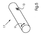
- Such screen materials 10 are used in rotary screen printing:
- a screen 17 is indicated with a flat screen material 10 in a cylindrical sleeve shape for rotary screen printing.
- the screen material 10 is held by unspecified tails in its cylindrical shape.
- Inside the sieve 17 is a non-visible squeegee of a screen printing unit to press paint through the screen material.
- the orientation of the doctor blade may be parallel to the axis of rotation of the screen 17.
- the circumferential direction U of the screen 17, in which this is rotated during printing, is indicated by a double arrow.
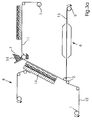
- FIG. 1 a first method according to the invention for producing a screen structure 10 is shown.
- a first fabric layer 11 is provided on a first supply roll 1 and a second fabric layer 12 is provided on a second supply roll 1.
- the fabric layers 11, 12 may already be preconditioned, for example nickel-plated.
- the two fabric layers 11, 12 are brought together via deflection rollers in the transport direction T, such that the first fabric layer 11 and the second fabric layer 12 contact each other. Contact must be made at the latest in the area of the dipping roller 18.
- the two fabric layers 11, 12 are passed around a cathode 19 and the dipping roller 18 through a galvanic bath 3, for example a nickel bath with anode 4, and galvanized electrochemically.
- first fabric layer 11 and second fabric layer 12 are nickel-plated in such a way that both fabric layers 11, 12 are firmly joined together, thus creating a fabric composite 13.
- the fabric composite 13 can be washed out in a subsequent washing station 5 and dried in a subsequent drying station 6 before it is wound onto a take-up reel 9. While in FIG. 1 If only one electroplating bath 3 is shown, the electroplating process can take place in several successive steps, for example using a plurality of electroplating baths 3.
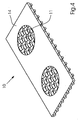
- Various sieve structures 10 made in accordance with this method are described in Figure 2a - c shown.
- the screen structure 10 may have a photo layer 14, which allows the use of the screen structure 10 in screen printing.
- the sieve structure 10 has a fabric composite 13, which is composed of a first fabric layer 11 and a second fabric layer 12.
- the first fabric layer 11 and the second fabric layer 12 are interconnected by a metal layer 15.
- a metal layer 15 is applied on the upper side of the first fabric layer 11 and on the underside of the second fabric layer 12.
- the metal layer 15 may be, for example, a nickel layer which has been applied by nickel plating in a galvanic nickel bath.
- the thickness of the tissue composite 13 is composed of the Thickness D1 of the first fabric layer 11 and the thickness D2 of the second fabric layer 12. In addition, twice the thickness of the applied metal layer 15 contributes to the overall thickness.
- Fig. 2c shows a screen structure 10, which consists of two different fabric layers 11 and 12.
- the first fabric layer 11 and the second fabric layer 12 may each be provided in advance with a metal layer 15 separately in a preceding step.
- the thus metallized fabric layers 11, 12 can then be connected to one another by an additional metal layer 15 as described above.
- FIG. 3a an alternative method of manufacturing a screen structure 10 is shown.
- a first fabric layer 11 which may be uncoated or precoated
- a second fabric layer 12 is provided on a first supply roll 1 .
- the first fabric layer 11 is provided by an applicator 7 with an emulsion 14.
- a capillary film can be applied to the emulsion layer 14 in a device 8.
- the thus prepared first fabric layer 11 is brought together via deflection rollers 2 with a second fabric layer 12 and both fabric layers 11, 12 pressed together, so that a fabric composite 13 is formed.
- FIG. 3b A screen structure 10 produced according to this method is shown in FIG. 3b shown.
- a first fabric layer 11 and a second fabric layer 12 are laminated together by two layers of emulsions 14 and form a fabric composite 13.
- the distance S between the two fabric layers 11, 12 can be varied around the Thickness of the fabric composite 13 to influence.
- a carrier film 16 may additionally be provided on one side of the fabric composite 13.
Landscapes
- Engineering & Computer Science (AREA)
- Manufacturing & Machinery (AREA)
- Physics & Mathematics (AREA)
- Plasma & Fusion (AREA)
- Textile Engineering (AREA)
- Printing Plates And Materials Therefor (AREA)
- Screen Printers (AREA)
- Electroplating Methods And Accessories (AREA)
- Manufacture Or Reproduction Of Printing Formes (AREA)
Description
- Die Erfindung betrifft ein Verfahren zum Herstellen einer Siebstruktur mit den Merkmalen von Anspruch 1 als auch eine Siebstruktur mit den oberbegrifflichen Merkmalen von Anspruch 5
- Die industrielle Anwendung von Sieben und Geweben ist aus verschiedenen Fachgebieten bekannt.
Bei der Anwendung im Bereich der Filtration ist die quadratische Maschenform die übliche Ausführungsform. Für die Druckanwendung hat man diese Maschenform übernommen. Mit den verfügbaren Fotoschichten und den bekannten Auftragsverfahren lässt sich eine vernünftige Bildauflösung nur mit einer großen Zahl von "Abstützungen" erreichen. Deshalb werden zunehmend Gewebe mit hohen Maschenzahlen verwendet. - Beim Elektronikdruck werden möglichst dünne Siebe bzw. Gewebe mit möglichst dünnem Draht eingesetzt um einen guten Durchfluss der Pasten zu gewährleisten und um allerfeinste Bildmotive zu ermöglichen.
Bei der Solarzellenbeschichtung wird ein hoher Pastenauftrag und eine präzise und feine Bildauflösung gefordert. Z.B. zum Auftragen von Leiterbahnen als Stromfinger mit möglichst geringer Abdeckung der Solarzellen, um so einen hohen Wirkungsgrad der Solarzellen sicherzustellen.
Die für den Elektronikdruck verwendeten Siebe bzw. Gewebesorten sind sehr teuer und empfindlich in der Verarbeitung, so dass sie für die Herstellung von Siebdruckplatten für den rotativen Siebdruck ungeeignet sind. Die fehlende Eignung wird auch dadurch bedingt, dass die Siebgewebe beim Rotationssieb nur in einer Richtung, nämlich der Zylinderlängsachse gespannt werden können, im Flachsiebdruck hingegen jedoch in zwei Dimensionen. - Beim Rotationssiebdruck wird die Farbe durch den hydrodynamischen Druck, welcher bei der Rotation des Siebes und bei angestellter Rakel vor der Rakelbrust entsteht, durch das Sieb transportiert. Konstruktionsbedingt lassen sich nur offene oder halboffene Rakelsysteme einsetzen, so dass der dynamische Druck von vielen Faktoren beeinflusst wird wie Viskosität, Füllmenge und Rotationsgeschwindigkeit. Durch eine Erhöhung der Rotationsgeschwindigkeit oder der Farbmenge kann der hydrodynamische Druck einfach verstärkt werden.
Ein solches Rotationssiebdruckwerk ist beispielsweise in derWO 99/19146 A1 - Als Grundstrukturen für Siebmaterialien werden nach dem Stand der Technik Edelstahlgewebe mit Leinenbindung verwendet. Das Verhältnis von Sieböffnung, Kontaktfläche und Gewebedicke hat sich als geeignet erwiesen. Die Dicke der Struktur, also die Gewebedicke (Ausgangsmaß vor Kalandrieren) entspricht in etwa der zweifachen Drahtstärke. Die Grundstruktur wird einem weiteren Schritt in einem Kalandrierprozess bearbeitet und so auf die gewünschte Rohgewebedicke gebracht. Auch wird so eine höhere Glätte des Siebes und damit ein geringerer Sieb- und Rakelverschleiß erreicht. Im sich anschließenden Vernickelungsvorgang wird das Gewebe zwecks einer höheren Verschleißfestigkeit verstärkt und die Abstützungspunkte im Bereich der Kreuzungspunkte vergrößert.
- Ein Verfahren zur Herstellung solcher Siebmaterialien ist beispielsweise in der
EP 0 182 195 A2 beschrieben. - Alternativ ist auch die Verwendung von Metallvliesen, Kunststoffgeweben, Lochblechen, Metallfolien, auch in Kombination miteinander bekannt.
- Aus der
US 1,594,770 A ist es bekannt, ein Gewebe durch elektrochemisches Galvanisieren mit einem Metall zu verstärken. Auch bekannt ist es, zwei Gewebelagen mittels eines dünnen Films von niedrig schmelzenden Metallen wie z.B. Zinn, Blei oder Cadmium zu verbinden. - Um die Stabilität des Siebmaterials sicherzustellen, wird in der Regel eine engmaschige Siebstruktur mit vielen Abstützpunkten gewählt. Nachteilig dabei ist, dass das theoretische Farbauftragsvolumen, welches durch die Gewebedicke und die prozentuale offene Fläche der Siebstruktur bestimmt wird, sehr beschränkt ist. Besonders dem Drucken von Linien mit geringer Breite bei gleichzeitig großer Höhe, wie das beispielsweise bei der Solarzellenfertigung erforderlich ist, sind Grenzen gesetzt.
- Aufgabe der vorliegenden Erfindung ist es, eine Siebstruktur zu schaffen und ein Verfahren zum Herstellen einer solchen Siebstruktur zu beschreiben, wobei die Siebstruktur eine besonders hohe Stabilität aufweist. Weitere Aufgabe ist es, eine Siebstruktur zu schaffen und ein Verfahren zum Herstellen einer solchen Siebstruktur zu beschreiben, wobei die Siebstruktur bei Anwendung im Siebdruck ein größeres Farbauftragsvolumen besitzt.
- Gelöst wird diese Aufgabe durch die Verfahren mit den Merkmalen von Anspruch 1 als auch durch die Siebstrukturen mit den Merkmalen von Anspruch 5.
- Das erfindungsgemäße Verfahren dient dem Herstellen einer Siebstruktur mit mindestens zwei siebartigen Gewebelagen, wobei auf einer ersten Rolle eine erste bahnförmige Gewebelage und auf einer zweiten Rolle eine zweite bahnförmige Gewebelage bereitgestellt werden. Unter einer Gewebelage wird in dieser Erfindung eine flächenförmige Struktur verstanden, welche sowohl eine gewebte Flächenstruktur als auch Lochbleche, Vliese, elektrogeformte Schablonen und Folien umfasst. Erfindungsgemäß werden die erste und die zweite Gewebelage zusammengeführt, insbesondere über Umlenkrollen, so dass die erste und die zweite Gewebelage einander kontaktieren. In vorteilhafter Weise werden die erste und die zweite Gewebelage gemeinsam metallisiert, derart, dass das aufgebrachte Metall die beiden Gewebelagen fest miteinander verbindet und ein Gewebeverbund geschaffen wird. Eine dritte Gewebelage kann bzw. weitere Gewebelagen können gleichermaßen verbunden werden, um einen noch dickeren Gewebeverbund zu schaffen.
- In vorteilhafter Weiterbildung des erfindungsgemäßen Verfahrens erfolgt nachfolgend ein Spülen und Trocknen des Gewebeverbundes und gegebenenfalls ein Aufbringen einer lichtempfindlichen Fotoschicht oder einer lokal entfernbaren Polymerschicht, wenn die Siebstruktur für den Siebdruck verwendet werden soll, bevor der Gewebeverbund auf einer dritten Rolle aufgewickelt wird.
- In einer ersten Variante erfolgt das Metallisieren, welches die Verbindung der beiden Gewebelagen bewirkt, als chemisches Metallisieren mit außenstromloser Metallabscheidung, als sogenannte reduktive Metallabscheidung.
- In einer besonders bevorzugten zweiten Alternative erfolgt das Metallisieren, welches die beiden Gewebelagen miteinander verbindet, als elektrochemisches Galvanisieren, welches insbesondere in einem Nickelbad erfolgt.
- Alternativ zum Nickelbad kann beispielsweise auch ein Kupferbad oder ein Zinnbad eingesetzt werden. Auch kann das Bad eine Kombination verschiedener Metalle enthalten, z.B. Nickel und Silber.
- Die Erfindung betrifft auch eine Siebstruktur, welche insbesondere für den Siebdruck geeignet ist, mit mindestens zwei im Wesentlichen parallel zueinander angeordneten siebartigen Gewebelagen, wobei diese Siebstruktur insbesondere gemäß dem obenstehend beschriebenen Verfahren gefertigt ist. Erfindungsgemäß sind die Gewebelagen mit einer galvanisch aufgebrachten Metallschicht versehen und die Gewebelagen werden durch diese Metallschicht miteinander verbunden. In einer bevorzugten Ausführungsform besteht die Metallschicht hauptsächlich aus Nickel. Alternativ können auch andere Metalle wie beispielsweise Kupfer oder Zinn eingesetzt werden. Auch kann eine Kombination verschiedener Metalle eingesetzt werden, z.B. Nickel und Silber.
Ein alternatives Anwendungsgebiet der Siebstruktur ist die Filtration. - In vorteilhafter Weiterbildung der erfindungsgemäßen Siebstruktur ist eine jeweilige Gewebelage ein Stahlgewebe aus dünnen Drähten. Dieses weist eine hohe Stabilität auf und ist besonders einfach elektrochemisch zu galvanisieren. Alternativ kann jedoch auch ein vorbehandeltes, elektrisch leitend gemachtes Kunststoffgewebe, z.B. Polyestergewebe eingesetzt werden. Die Gewebelagen können dabei jeweils von unterschiedlichem Gewebetyp sein. Ein Gewebetyp wird hierbei definiert über die Maschenform, welche als Quadratmasche oder Längsmasche ausgeführt sein kann, als auch über die Bindungsart. Der Gewebetyp ist dabei in Abhängigkeit von der geplanten Verwendung der Siebstruktur auszuwählen.
- Die erfindungsgemäßen Siebstrukturen haben den Vorteil, dass sie ein besonders großes Farbauftragsvolumen besitzen und somit ein besonders großes Verhältnis von gedruckter Linienhöhe zu Linienbreite ermöglicht wird. Ein weiterer Vorteil besteht darin, dass die Siebstrukturen eine besonders hohe Stabilität aufweisen, was ein besonders passergenaues Drucken von feinen Linien ermöglicht als auch eine höhere Lebensdauer der Siebstrukturen bewirkt.
- Die beschriebene Erfindung und die beschriebenen vorteilhaften Weiterbildungen der Erfindung stellen auch in beliebiger Kombination miteinander vorteilhafter Weiterbildungen der Erfindung dar.
- Hinsichtlich weiterer Vorteile und in konstruktiver und funktioneller Hinsicht vorteilhafte Ausgestaltungen der Erfindung wird auf die Unteransprüche sowie die Beschreibung von Ausführungsbeispielen unter Bezugnahme auf die beiliegenden Figuren verwiesen.
- Die Erfindung soll anhand beigefügter Figuren noch näher erläutert werden. Einander entsprechende Elemente und Bauteile sind in den Figuren mit gleichen Bezugszeichen versehen. Zugunsten einer besseren Übersichtlichkeit der Figuren wurde auf eine maßstabsgetreue Darstellung verzichtet.
- Es zeigen in schematischer Darstellung:
- Figur 1:
- ein erstes erfindungsgemäßes Verfahren zur Herstellung einer Siebstruktur
- Figur 2a - c:
- verschiedene mit diesem Verfahren hergestellte Siebstrukturen
- Figur 3a:
- ein alternatives Verfahren zur Herstellung einer Siebstruktur
- Figur 3b:
- die auf diesem Wege hergestellte Siebstruktur
- Figur 4:
- eine Siebstruktur gemäß dem Stand der Technik
- Figur 5:
- die Anwendung der Siebstruktur als Rotationssiebdrucksieb
-
Figur 4 zeigt ein flächiges Siebmaterial 10 mit einer Gewebelage 11 gemäß dem Stand der Technik, welches einseitig mit einer Photo-Polymerbeschichtung 14 versehen ist (Direktschablone). In einer nicht dargestellten alternativen Ausführungsform kann eine bereits bebilderte Folie auf die Siebstruktur 10 aufgebracht werden (Indirektschablone). Das vernickelte flächige Siebmaterial 10 ist dabei einteilig aus einem Gewebe 11 aufgebaut. Dabei sind verschiedene Gewebeformen möglich, welche auch als Gewebetyp bezeichnet werden. - Derartige Siebmaterialien 10 finden Verwendung im Rotationssiebdruck: In
Figur 5 ist ein Sieb 17 mit einem flächigen Siebmaterial 10 in zylindrischer Hülsenform für den rotativen Siebdruck angedeutet. Das Siebmaterial 10 wird dabei durch nicht näher bezeichnete Endstücke in seiner zylindrischen Form gehalten. Im Innern des Siebes 17 befindet sich ein nicht sichtbares Rakel eines Siebdruckwerks, um Farbe durch das Siebmaterial zu pressen. Die Ausrichtung des Rakels kann parallel zur Rotationsachse des Siebes 17 sein. Die Umfangsrichtung U des Siebes 17, in welche dieses beim Drucken rotiert wird, ist dabei mit einem Doppelpfeil angedeutet. - In
Figur 1 ist ein erstes erfindungsgemäßes Verfahren zur Herstellung einer Siebstruktur 10 dargestellt. Auf einer ersten Vorratsrolle 1 wird eine erste Gewebelage 11 bereitgestellt und auf einer zweiten Vorratsrolle 1 wird eine zweite Gewebelage 12 bereitgestellt. Die Gewebelagen 11, 12 können bereits vorkonditioniert, z.B. vernickelt sein. Die beiden Gewebelagen 11, 12 werden über Umlenkrollen in Transportrichtung T zusammengeführt, derart, dass sich die erste Gewebelage 11 und die zweite Gewebelage 12 kontaktieren. Kontakt muss dabei spätestens im Bereich der Tauchwalze 18 hergestellt sein. Die beiden Gewebelagen 11, 12 werden um eine Kathode 19 und die Tauchwalze 18 herum durch ein Galvanikbad 3, zum Beispiel ein Nickelbad mit Anode 4, hindurch geführt und dabei elektrochemisch galvanisiert. Im Falle der Verwendung eines Nickelbades 3 werden erste Gewebelage 11 und zweite Gewebelage 12 derart vernickelt, dass beide Gewebelagen 11, 12 fest miteinander verbunden sind und so ein Gewebeverbund 13 geschaffen wird. Der Gewebeverbund 13 kann in einer nachfolgenden Waschstation 5 ausgewaschen und in einer nachfolgenden Trockenstation 6 getrocknet werden, bevor er auf eine Aufwickelrolle 9 aufgewickelt wird. Während inFigur 1 nur ein Galvanikbad 3 dargestellt ist, kann der Galvanisierungsprozess in mehreren aufeinanderfolgenden Schritten erfolgen, beispielsweise unter Verwendung von mehreren Galvanikbädern 3.
Verschiedene gemäß diesem Verfahren hergestellte Siebstrukturen 10 werden inFigur 2a - c dargestellt. Die Siebstruktur 10 kann dabei eine Fotoschicht 14 aufweisen, welche die Verwendung der Siebstruktur 10 im Siebdruck ermöglicht. Die Siebstruktur 10 besitzt einen Gewebeverbund 13, welcher sich aus einer ersten Gewebelage 11 und einer zweiten Gewebelage 12 zusammensetzt. Die erste Gewebelage 11 und die zweite Gewebelage 12 sind durch eine Metallschicht 15 miteinander verbunden. Auch an der Oberseite der ersten Gewebelage 11 und an der Unterseite der zweiten Gewebelage 12 wird eine Metallschicht 15 aufgebracht. Bei der Metallschicht 15 kann es sich dabei beispielsweise um eine Nickelschicht handeln, welche durch Vernickeln in einem galvanischen Nickelbad aufgebracht wurde. Die Dicke des Gewebeverbundes 13 setzt sich dabei zusammen aus der Dicke D1 der ersten Gewebelage 11 und der Dicke D2 der zweiten Gewebelage 12. Zusätzlich trägt auch die zweifache Dicke der aufgebrachten Metallschicht 15 zur Gesamtdicke bei. Es wird ersichtlich, dass aufgrund der größeren Dicke D1 + D2 des Gewebeverbunds 13 im Vergleich zu einer Dicke D1 der ersten Gewebelage bzw. D2 der zweiten Gewebelage eine Siebstruktur mit höherer Stabilität geschaffen wurde. Wird die Siebstruktur 10 für den Siebdruck verwendet, so bietet diese ein erhöhtes Farbauftragsvolumen, da dieses unmittelbar von der Dicke D1 + D2 der Siebstruktur 10 abhängt.Fig. 2c zeigt eine Siebstruktur 10, welche aus zwei unterschiedlichen Gewebelagen 11 und 12 besteht.
In einer alternativen, nicht dargestellten Ausführungsvariante können die erste Gewebelage 11 und die zweite Gewebelage 12 jeweils in einem vorangehenden Schritt vorab separat mit einer Metallschicht 15 versehen werden. Die so metallisierten Gewebelagen 11, 12 können dann wie oben beschrieben durch eine zusätzliche Metallschicht 15 miteinander verbunden werden. In anderen Worten: es erfolgt zuerst ein Galvanisieren der jeweiligen Gewebelagen wie allgemein üblich. Nachfolgend werden die galvanisierten Gewebelagen gemäß der Erfindung miteinander verbunden. - In
Figur 3a ist ein alternatives Verfahren zur Herstellung einer Siebstruktur 10 dargestellt. Auf einer ersten Vorratsrolle 1 wird eine erste Gewebelage 11, welche unbeschichtet oder vorbeschichtet sein kann, und auf einer zweiten Vorratsrolle 1 eine zweite Gewebelage 12 bereitgestellt. Die erste Gewebelage 11 wird dabei durch ein Auftragswerk 7 mit einer Emulsion 14 versehen. Nachfolgend kann in einer Einrichtung 8 ein Kapillarfilm auf die Emulsionsschicht 14 aufgebracht werden. Die so vorbereitete erste Gewebelage 11 wird über Umlenkrollrollen 2 mit einer zweiten Gewebelage 12 zusammengeführt und beide Gewebelagen 11, 12 aneinandergepresst, so dass ein Gewebeverbund 13 entsteht. Um eine stabile Verbindung der beiden Gewebelagen 11, 12 sicherzustellen, wird die Emulsion in einer Trockenstation 6 getrocknet, bevor der Gewebeverbund 13 auf einer Aufwickelrolle 9 aufgewickelt wird. Eine gemäß diesem Verfahren hergestellte Siebstruktur 10 ist inFigur 3b dargestellt. Eine erste Gewebelage 11 und eine zweite Gewebelage 12 sind durch zwei Schichten von Emulsionen 14 zusammenkaschiert und bilden einen Gewebeverbund 13. Der Abstand S zwischen den beiden Gewebelagen 11, 12 kann variiert werden um die Dicke des Gewebeverbundes 13 zu beeinflussen. Auf einer Seite des Gewebeverbunds 13 kann zusätzlich eine Trägerfolie 16 vorgesehen sein. -
- 1
- Vorratsrolle
- 2
- Umlenkrolle
- 3
- Galvanikbad, z. B. Nickelbad
- 4
- Anode
- 5
- Waschstation
- 6
- Trockenstation
- 7
- Auftragswerk
- 8
- Einrichtung zum Aufbringen eines Kapillarfilmes
- 9
- Aufwickelrolle
- 10
- Siebstruktur
- 11
- erste Gewebelage
- 12
- zweite Gewebelage
- 13
- Gewebeverbund
- 14
- Emulsion / Fotoschicht / Hotmelt-Klebstoff
- 15
- Metallschicht
- 16
- Trägerfolie
- 17
- Rotationssiebdrucksieb
- 18
- Tauchwalze
- 19
- Kathode
- D1
- Dicke der ersten Gewebelage
- D2
- Dicke der zweiten Gewebelage
- S
- Abstand der Gewebelagen
- T
- Transportrichtung
- U
- Umfangsrichtung
Claims (7)
- Verfahren zum Herstellen einer Siebstruktur (10) mit mindestens zwei Gewebelagen (11, 12),
wobei auf einer ersten Rolle (1) eine erste Gewebelage (11) und auf einer zweiten Rolle (1) eine zweite Gewebelage (12) bereitgestellt werden,
wobei die erste und die zweite Gewebelage (11, 12) zusammengeführt werden und einander kontaktieren,
wobei die erste und die zweite Gewebelage (11, 12) gemeinsam metallisiert werden und das aufgebrachte Metall (15) die beiden Gewebelagen (11, 12) fest miteinander verbindet und ein Gewebeverbund (13) geschaffen wird. - Verfahren zum Herstellen einer Siebstruktur nach Anspruch 1
dadurch gekennzeichnet,
dass ein nachfolgendes Spülen (5) und Trocknen (6) des Gewebeverbundes (13) und ggfs. ein Aufbringen einer lichtempfindlichen Fotoschicht (14) oder einer lokal entfernbaren Polymerschicht erfolgt bevor der Gewebeverbund (13) auf einer dritten Rolle (9) aufgewickelt wird. - Verfahren zum Herstellen einer Siebstruktur nach Anspruch 1 oder 2
dadurch gekennzeichnet,
dass das Metallisieren als chemisches Metallisieren mit außenstromloser Metallabscheidung (15) erfolgt. - Verfahren zum Herstellen einer Siebstruktur nach Anspruch 1 oder 2
dadurch gekennzeichnet,
dass das Metallisieren als elektrochemisches Galvanisieren erfolgt, insbesondere in einem Nickelbad (3). - Siebstruktur (10) insbesondere für den Siebdruck mit mindestens zwei im Wesentlichen parallel zueinander angeordneten Gewebelagen (11, 12), insbesondere gefertigt gemäß dem Verfahren nach Anspruch 1,
dadurch gekennzeichnet,
dass die Gewebelagen (11, 12) mit einer galvanisch aufgebrachten Metallschicht (15) versehen und durch die Metallschicht (15) miteinander verbunden sind, und dass insbesondere die Metallschicht (15) hauptsächlich aus Nickel besteht. - Siebstruktur nach Anspruch 5,
dadurch gekennzeichnet,
dass eine jeweilige Gewebelage (11, 12) ein Stahlgewebe ist. - Siebstruktur nach Anspruch 5 bis 6,
dadurch gekennzeichnet,
dass die Gewebelagen (11, 12) jeweils von unterschiedlichem Gewebetyp sind.
Applications Claiming Priority (1)
| Application Number | Priority Date | Filing Date | Title |
|---|---|---|---|
| DE102013009462.3A DE102013009462A1 (de) | 2013-06-06 | 2013-06-06 | Verfahren zum Herstellen einer Siebstruktur |
Publications (2)
| Publication Number | Publication Date |
|---|---|
| EP2810778A1 EP2810778A1 (de) | 2014-12-10 |
| EP2810778B1 true EP2810778B1 (de) | 2016-01-20 |
Family
ID=50771127
Family Applications (1)
| Application Number | Title | Priority Date | Filing Date |
|---|---|---|---|
| EP14169388.7A Active EP2810778B1 (de) | 2013-06-06 | 2014-05-22 | Verfahren zum Herstellen einer Siebstruktur |
Country Status (5)
| Country | Link |
|---|---|
| US (1) | US20140360390A1 (de) |
| EP (1) | EP2810778B1 (de) |
| JP (1) | JP2014237316A (de) |
| CN (1) | CN104228313B (de) |
| DE (1) | DE102013009462A1 (de) |
Families Citing this family (5)
| Publication number | Priority date | Publication date | Assignee | Title |
|---|---|---|---|---|
| US10766223B2 (en) * | 2015-11-02 | 2020-09-08 | 3M Innovative Properties Company | Low gloss laminated article |
| JP6559588B2 (ja) * | 2016-02-01 | 2019-08-14 | タイガースポリマー株式会社 | 封止装置用弾性シートおよびその製造方法 |
| CN107020852B (zh) * | 2017-03-21 | 2019-01-18 | 华鸿控股集团有限公司 | 一种玻璃制品高光耐磨丝网印刷工艺 |
| US10349923B2 (en) * | 2017-04-24 | 2019-07-16 | Lyon Timothy L | Female urine strainers and samplers |
| CN121157502A (zh) * | 2021-04-15 | 2025-12-19 | 仓和精密制造(苏州)有限公司 | 一种印刷网版的制作方法 |
Family Cites Families (24)
| Publication number | Priority date | Publication date | Assignee | Title |
|---|---|---|---|---|
| US159770A (en) * | 1875-02-16 | Improvement in velocipedes | ||
| US1594770A (en) * | 1925-05-09 | 1926-08-03 | Dick Co Ab | Stencil sheet and process of producing the same |
| DE1951130U (de) * | 1965-12-08 | 1966-12-08 | Bayer Ag | Metallisierte gewebe- oder gewirkbahn. |
| DE6751332U (de) * | 1968-04-22 | 1969-02-06 | Carl Klingspor | Siebe aus metallisiertem kunststoff-gewebe |
| US3759799A (en) * | 1971-08-10 | 1973-09-18 | Screen Printing Systems | Method of making a metal printing screen |
| CH602943A5 (de) * | 1975-05-02 | 1978-08-15 | Buser Ag Maschf Fritz | |
| NL7607139A (nl) * | 1976-06-29 | 1978-01-02 | Stork Brabant Bv | Werkwijze voor het vervaardigen van een naad- loze cilindrische sjabloon, alsmede gaassja- bloon verkregen onder toepassing van deze werkwijze. |
| US4291116A (en) * | 1977-10-28 | 1981-09-22 | Tibbetts Charles C | Method of image reproduction and materials therefor |
| DE3441593A1 (de) | 1984-11-14 | 1986-05-22 | Ferd. Rüesch AG, St. Gallen | Verfahren und vorrichtung zum herstellen von siebdruckgeweben fuer siebdruckzylinder |
| GB8705075D0 (en) * | 1987-03-04 | 1987-04-08 | Pilkington Brothers Plc | Printing |
| JPH02274895A (ja) * | 1989-04-14 | 1990-11-09 | Katayama Tokushu Kogyo Kk | 金属多孔体及びその製造方法 |
| DE19738874A1 (de) * | 1996-09-13 | 1998-04-23 | Sefar Ag | Verfahren zum Herstellen einer Gewebebahn, insbesondere für eine Siebdruckform, sowie Gewebe, insbesondere Siebdruckgewebe |
| JPH10315647A (ja) * | 1997-05-16 | 1998-12-02 | Toppan Printing Co Ltd | スクリーン印刷版 |
| SE510341C2 (sv) * | 1997-08-19 | 1999-05-17 | Sca Research Ab | Metod och anordning för formning av en flerskiktsbana |
| KR20010031083A (ko) | 1997-10-14 | 2001-04-16 | 갈루스 페르트. 뤼쉬 아게 | 실크스크린 인쇄 장치 |
| US20040251175A1 (en) * | 1998-10-30 | 2004-12-16 | Adams Thomas C. | Apparatuses and methods for making glued screen assemblies |
| US6148496A (en) * | 1999-04-09 | 2000-11-21 | The Procter & Gamble Company | Method for making a seamless apertured metal belt |
| JP2001080187A (ja) * | 1999-09-17 | 2001-03-27 | Riso Kagaku Corp | 孔版印刷装置 |
| JP2001113850A (ja) * | 1999-10-19 | 2001-04-24 | Matsushita Electric Ind Co Ltd | スクリーン印刷版 |
| CA2463074A1 (en) * | 2001-10-19 | 2003-04-24 | Varco I/P, Inc. | A method of making a screen for a vibratory separator, a screen and an apparatus for making a screen |
| KR100458313B1 (ko) * | 2002-01-11 | 2004-11-26 | 최용석 | 실크스크린 인쇄방법 |
| JP5024245B2 (ja) * | 2008-09-09 | 2012-09-12 | 株式会社ボンマーク | スクリーン印刷用メタルマスク及びその製造方法 |
| JP5453870B2 (ja) * | 2009-03-27 | 2014-03-26 | 協立化学産業株式会社 | 接着剤リブ形成用メタルマスク及びその製造方法 |
| DE102010021062A1 (de) * | 2010-05-19 | 2011-11-24 | Gallus Ferd. Rüesch AG | Flächiges Siebmaterial und Sieb |
-
2013
- 2013-06-06 DE DE102013009462.3A patent/DE102013009462A1/de not_active Withdrawn
-
2014
- 2014-05-21 CN CN201410216221.2A patent/CN104228313B/zh active Active
- 2014-05-22 EP EP14169388.7A patent/EP2810778B1/de active Active
- 2014-06-03 US US14/294,262 patent/US20140360390A1/en not_active Abandoned
- 2014-06-06 JP JP2014117580A patent/JP2014237316A/ja active Pending
Also Published As
| Publication number | Publication date |
|---|---|
| JP2014237316A (ja) | 2014-12-18 |
| US20140360390A1 (en) | 2014-12-11 |
| DE102013009462A1 (de) | 2014-12-11 |
| CN104228313A (zh) | 2014-12-24 |
| EP2810778A1 (de) | 2014-12-10 |
| CN104228313B (zh) | 2018-09-28 |
Similar Documents
| Publication | Publication Date | Title |
|---|---|---|
| EP2388142B1 (de) | Flächiges Siebmaterial und Sieb | |
| EP2810778B1 (de) | Verfahren zum Herstellen einer Siebstruktur | |
| WO2010034300A2 (de) | Siebdruckform | |
| CH621516A5 (de) | ||
| DE69501405T2 (de) | Perforierte siebdruckschablone zum aufbringen und dosieren von mehr oder weniger dicken schichten eines viskosen produktes | |
| EP2356275A2 (de) | Gewebe, vorrichtung mit gewebe sowie herstellungsverfahren für gewebe | |
| DE3441593C2 (de) | ||
| DE102009033510A1 (de) | Gewebe, Vorrichtung mit Gewebe sowie Herstellungsverfahren für Gewebe | |
| EP0925196B1 (de) | Verfahren zum herstellen einer gewebebahn, insbesondere für eine siebdruckform, sowie gewebe, insbesondere siebdruckgewebe | |
| EP3107735B1 (de) | Siebdruckschablone und verfahren zu deren bebilderung | |
| DE2918063C3 (de) | Verfahren zur Herstellung einer Siebtrommel für den Rotationssiebdruck | |
| WO2009030409A2 (de) | Verfahren zum herstellen einer solarzelle | |
| EP2879882B1 (de) | Flächiges siebmaterial und sieb | |
| DE10238284B4 (de) | Verfahren zum Herstellen einer schaumförmigen Metallstruktur, Metallschaum sowie Anordnung aus einem Trägersubstrat und einem Metallschaum | |
| WO2010142274A2 (de) | Siebdruckform | |
| DD244525A5 (de) | Siebdruckschablone | |
| EP1149189A2 (de) | Verfahren zur herstellung einer selbsttragenden metallfolie | |
| DE102014110340B4 (de) | Drahtgewebeeinheit | |
| EP1429924A1 (de) | Beschichtungsvorrichtung | |
| DE1934410C3 (de) | Verfahren zur Herstellung von Flachschablonen für den Schablonendruck | |
| DE2051728B2 (de) | Verfahren zum Herstellen eines Schablonensiebes | |
| DE1920458A1 (de) | Verfahren zur Herstellung eines freitragenden Druckrasters | |
| DE29824945U1 (de) | Selbsttragende Metallfolie |
Legal Events
| Date | Code | Title | Description |
|---|---|---|---|
| PUAI | Public reference made under article 153(3) epc to a published international application that has entered the european phase |
Free format text: ORIGINAL CODE: 0009012 |
|
| 17P | Request for examination filed |
Effective date: 20140522 |
|
| AK | Designated contracting states |
Kind code of ref document: A1 Designated state(s): AL AT BE BG CH CY CZ DE DK EE ES FI FR GB GR HR HU IE IS IT LI LT LU LV MC MK MT NL NO PL PT RO RS SE SI SK SM TR |
|
| AX | Request for extension of the european patent |
Extension state: BA ME |
|
| R17P | Request for examination filed (corrected) |
Effective date: 20150610 |
|
| RBV | Designated contracting states (corrected) |
Designated state(s): AL AT BE BG CH CY CZ DE DK EE ES FI FR GB GR HR HU IE IS IT LI LT LU LV MC MK MT NL NO PL PT RO RS SE SI SK SM TR |
|
| GRAP | Despatch of communication of intention to grant a patent |
Free format text: ORIGINAL CODE: EPIDOSNIGR1 |
|
| RIC1 | Information provided on ipc code assigned before grant |
Ipc: B41C 1/14 20060101AFI20150702BHEP Ipc: B32B 7/04 20060101ALI20150702BHEP Ipc: B41N 1/24 20060101ALI20150702BHEP Ipc: B41F 15/34 20060101ALI20150702BHEP |
|
| INTG | Intention to grant announced |
Effective date: 20150731 |
|
| GRAS | Grant fee paid |
Free format text: ORIGINAL CODE: EPIDOSNIGR3 |
|
| GRAA | (expected) grant |
Free format text: ORIGINAL CODE: 0009210 |
|
| AK | Designated contracting states |
Kind code of ref document: B1 Designated state(s): AL AT BE BG CH CY CZ DE DK EE ES FI FR GB GR HR HU IE IS IT LI LT LU LV MC MK MT NL NO PL PT RO RS SE SI SK SM TR |
|
| REG | Reference to a national code |
Ref country code: GB Ref legal event code: FG4D Free format text: NOT ENGLISH |
|
| REG | Reference to a national code |
Ref country code: CH Ref legal event code: EP |
|
| REG | Reference to a national code |
Ref country code: IE Ref legal event code: FG4D Free format text: LANGUAGE OF EP DOCUMENT: GERMAN |
|
| REG | Reference to a national code |
Ref country code: AT Ref legal event code: REF Ref document number: 771510 Country of ref document: AT Kind code of ref document: T Effective date: 20160215 |
|
| REG | Reference to a national code |
Ref country code: DE Ref legal event code: R096 Ref document number: 502014000313 Country of ref document: DE |
|
| REG | Reference to a national code |
Ref country code: NL Ref legal event code: FP |
|
| REG | Reference to a national code |
Ref country code: LT Ref legal event code: MG4D |
|
| PG25 | Lapsed in a contracting state [announced via postgrant information from national office to epo] |
Ref country code: FI Free format text: LAPSE BECAUSE OF FAILURE TO SUBMIT A TRANSLATION OF THE DESCRIPTION OR TO PAY THE FEE WITHIN THE PRESCRIBED TIME-LIMIT Effective date: 20160120 Ref country code: IT Free format text: LAPSE BECAUSE OF FAILURE TO SUBMIT A TRANSLATION OF THE DESCRIPTION OR TO PAY THE FEE WITHIN THE PRESCRIBED TIME-LIMIT Effective date: 20160120 Ref country code: ES Free format text: LAPSE BECAUSE OF FAILURE TO SUBMIT A TRANSLATION OF THE DESCRIPTION OR TO PAY THE FEE WITHIN THE PRESCRIBED TIME-LIMIT Effective date: 20160120 Ref country code: NO Free format text: LAPSE BECAUSE OF FAILURE TO SUBMIT A TRANSLATION OF THE DESCRIPTION OR TO PAY THE FEE WITHIN THE PRESCRIBED TIME-LIMIT Effective date: 20160420 Ref country code: HR Free format text: LAPSE BECAUSE OF FAILURE TO SUBMIT A TRANSLATION OF THE DESCRIPTION OR TO PAY THE FEE WITHIN THE PRESCRIBED TIME-LIMIT Effective date: 20160120 Ref country code: GR Free format text: LAPSE BECAUSE OF FAILURE TO SUBMIT A TRANSLATION OF THE DESCRIPTION OR TO PAY THE FEE WITHIN THE PRESCRIBED TIME-LIMIT Effective date: 20160421 |
|
| PG25 | Lapsed in a contracting state [announced via postgrant information from national office to epo] |
Ref country code: BE Free format text: LAPSE BECAUSE OF NON-PAYMENT OF DUE FEES Effective date: 20160531 Ref country code: RS Free format text: LAPSE BECAUSE OF FAILURE TO SUBMIT A TRANSLATION OF THE DESCRIPTION OR TO PAY THE FEE WITHIN THE PRESCRIBED TIME-LIMIT Effective date: 20160120 Ref country code: SE Free format text: LAPSE BECAUSE OF FAILURE TO SUBMIT A TRANSLATION OF THE DESCRIPTION OR TO PAY THE FEE WITHIN THE PRESCRIBED TIME-LIMIT Effective date: 20160120 Ref country code: IS Free format text: LAPSE BECAUSE OF FAILURE TO SUBMIT A TRANSLATION OF THE DESCRIPTION OR TO PAY THE FEE WITHIN THE PRESCRIBED TIME-LIMIT Effective date: 20160520 Ref country code: LT Free format text: LAPSE BECAUSE OF FAILURE TO SUBMIT A TRANSLATION OF THE DESCRIPTION OR TO PAY THE FEE WITHIN THE PRESCRIBED TIME-LIMIT Effective date: 20160120 Ref country code: PL Free format text: LAPSE BECAUSE OF FAILURE TO SUBMIT A TRANSLATION OF THE DESCRIPTION OR TO PAY THE FEE WITHIN THE PRESCRIBED TIME-LIMIT Effective date: 20160120 Ref country code: LV Free format text: LAPSE BECAUSE OF FAILURE TO SUBMIT A TRANSLATION OF THE DESCRIPTION OR TO PAY THE FEE WITHIN THE PRESCRIBED TIME-LIMIT Effective date: 20160120 Ref country code: PT Free format text: LAPSE BECAUSE OF FAILURE TO SUBMIT A TRANSLATION OF THE DESCRIPTION OR TO PAY THE FEE WITHIN THE PRESCRIBED TIME-LIMIT Effective date: 20160520 |
|
| REG | Reference to a national code |
Ref country code: DE Ref legal event code: R097 Ref document number: 502014000313 Country of ref document: DE |
|
| PG25 | Lapsed in a contracting state [announced via postgrant information from national office to epo] |
Ref country code: DK Free format text: LAPSE BECAUSE OF FAILURE TO SUBMIT A TRANSLATION OF THE DESCRIPTION OR TO PAY THE FEE WITHIN THE PRESCRIBED TIME-LIMIT Effective date: 20160120 Ref country code: EE Free format text: LAPSE BECAUSE OF FAILURE TO SUBMIT A TRANSLATION OF THE DESCRIPTION OR TO PAY THE FEE WITHIN THE PRESCRIBED TIME-LIMIT Effective date: 20160120 |
|
| PLBE | No opposition filed within time limit |
Free format text: ORIGINAL CODE: 0009261 |
|
| STAA | Information on the status of an ep patent application or granted ep patent |
Free format text: STATUS: NO OPPOSITION FILED WITHIN TIME LIMIT |
|
| PG25 | Lapsed in a contracting state [announced via postgrant information from national office to epo] |
Ref country code: SK Free format text: LAPSE BECAUSE OF FAILURE TO SUBMIT A TRANSLATION OF THE DESCRIPTION OR TO PAY THE FEE WITHIN THE PRESCRIBED TIME-LIMIT Effective date: 20160120 Ref country code: RO Free format text: LAPSE BECAUSE OF FAILURE TO SUBMIT A TRANSLATION OF THE DESCRIPTION OR TO PAY THE FEE WITHIN THE PRESCRIBED TIME-LIMIT Effective date: 20160120 Ref country code: SM Free format text: LAPSE BECAUSE OF FAILURE TO SUBMIT A TRANSLATION OF THE DESCRIPTION OR TO PAY THE FEE WITHIN THE PRESCRIBED TIME-LIMIT Effective date: 20160120 Ref country code: CZ Free format text: LAPSE BECAUSE OF FAILURE TO SUBMIT A TRANSLATION OF THE DESCRIPTION OR TO PAY THE FEE WITHIN THE PRESCRIBED TIME-LIMIT Effective date: 20160120 |
|
| 26N | No opposition filed |
Effective date: 20161021 |
|
| PG25 | Lapsed in a contracting state [announced via postgrant information from national office to epo] |
Ref country code: LU Free format text: LAPSE BECAUSE OF FAILURE TO SUBMIT A TRANSLATION OF THE DESCRIPTION OR TO PAY THE FEE WITHIN THE PRESCRIBED TIME-LIMIT Effective date: 20160522 |
|
| REG | Reference to a national code |
Ref country code: IE Ref legal event code: MM4A |
|
| PG25 | Lapsed in a contracting state [announced via postgrant information from national office to epo] |
Ref country code: SI Free format text: LAPSE BECAUSE OF FAILURE TO SUBMIT A TRANSLATION OF THE DESCRIPTION OR TO PAY THE FEE WITHIN THE PRESCRIBED TIME-LIMIT Effective date: 20160120 Ref country code: BG Free format text: LAPSE BECAUSE OF FAILURE TO SUBMIT A TRANSLATION OF THE DESCRIPTION OR TO PAY THE FEE WITHIN THE PRESCRIBED TIME-LIMIT Effective date: 20160420 |
|
| REG | Reference to a national code |
Ref country code: FR Ref legal event code: ST Effective date: 20170131 |
|
| PG25 | Lapsed in a contracting state [announced via postgrant information from national office to epo] |
Ref country code: FR Free format text: LAPSE BECAUSE OF NON-PAYMENT OF DUE FEES Effective date: 20160531 |
|
| PG25 | Lapsed in a contracting state [announced via postgrant information from national office to epo] |
Ref country code: IE Free format text: LAPSE BECAUSE OF NON-PAYMENT OF DUE FEES Effective date: 20160522 |
|
| PG25 | Lapsed in a contracting state [announced via postgrant information from national office to epo] |
Ref country code: HU Free format text: LAPSE BECAUSE OF FAILURE TO SUBMIT A TRANSLATION OF THE DESCRIPTION OR TO PAY THE FEE WITHIN THE PRESCRIBED TIME-LIMIT; INVALID AB INITIO Effective date: 20140522 |
|
| PG25 | Lapsed in a contracting state [announced via postgrant information from national office to epo] |
Ref country code: MC Free format text: LAPSE BECAUSE OF FAILURE TO SUBMIT A TRANSLATION OF THE DESCRIPTION OR TO PAY THE FEE WITHIN THE PRESCRIBED TIME-LIMIT Effective date: 20160120 Ref country code: MT Free format text: LAPSE BECAUSE OF FAILURE TO SUBMIT A TRANSLATION OF THE DESCRIPTION OR TO PAY THE FEE WITHIN THE PRESCRIBED TIME-LIMIT Effective date: 20160120 Ref country code: MK Free format text: LAPSE BECAUSE OF FAILURE TO SUBMIT A TRANSLATION OF THE DESCRIPTION OR TO PAY THE FEE WITHIN THE PRESCRIBED TIME-LIMIT Effective date: 20160120 Ref country code: CY Free format text: LAPSE BECAUSE OF FAILURE TO SUBMIT A TRANSLATION OF THE DESCRIPTION OR TO PAY THE FEE WITHIN THE PRESCRIBED TIME-LIMIT Effective date: 20160120 |
|
| PG25 | Lapsed in a contracting state [announced via postgrant information from national office to epo] |
Ref country code: AL Free format text: LAPSE BECAUSE OF FAILURE TO SUBMIT A TRANSLATION OF THE DESCRIPTION OR TO PAY THE FEE WITHIN THE PRESCRIBED TIME-LIMIT Effective date: 20160120 Ref country code: TR Free format text: LAPSE BECAUSE OF FAILURE TO SUBMIT A TRANSLATION OF THE DESCRIPTION OR TO PAY THE FEE WITHIN THE PRESCRIBED TIME-LIMIT Effective date: 20160120 |
|
| GBPC | Gb: european patent ceased through non-payment of renewal fee |
Effective date: 20180522 |
|
| PG25 | Lapsed in a contracting state [announced via postgrant information from national office to epo] |
Ref country code: GB Free format text: LAPSE BECAUSE OF NON-PAYMENT OF DUE FEES Effective date: 20180522 |
|
| P01 | Opt-out of the competence of the unified patent court (upc) registered |
Effective date: 20230511 |
|
| PGFP | Annual fee paid to national office [announced via postgrant information from national office to epo] |
Ref country code: NL Payment date: 20250523 Year of fee payment: 12 |
|
| PGFP | Annual fee paid to national office [announced via postgrant information from national office to epo] |
Ref country code: DE Payment date: 20250531 Year of fee payment: 12 |
|
| PGFP | Annual fee paid to national office [announced via postgrant information from national office to epo] |
Ref country code: CH Payment date: 20250601 Year of fee payment: 12 |
|
| PGFP | Annual fee paid to national office [announced via postgrant information from national office to epo] |
Ref country code: AT Payment date: 20250526 Year of fee payment: 12 |