EP2808740B1 - Bilderzeugungsvorrichtung - Google Patents
Bilderzeugungsvorrichtung Download PDFInfo
- Publication number
- EP2808740B1 EP2808740B1 EP14169360.6A EP14169360A EP2808740B1 EP 2808740 B1 EP2808740 B1 EP 2808740B1 EP 14169360 A EP14169360 A EP 14169360A EP 2808740 B1 EP2808740 B1 EP 2808740B1
- Authority
- EP
- European Patent Office
- Prior art keywords
- recording medium
- transport
- shaft portion
- image forming
- disposed
- Prior art date
- Legal status (The legal status is an assumption and is not a legal conclusion. Google has not performed a legal analysis and makes no representation as to the accuracy of the status listed.)
- Active
Links
Images





Classifications
-
- G—PHYSICS
- G03—PHOTOGRAPHY; CINEMATOGRAPHY; ANALOGOUS TECHNIQUES USING WAVES OTHER THAN OPTICAL WAVES; ELECTROGRAPHY; HOLOGRAPHY
- G03G—ELECTROGRAPHY; ELECTROPHOTOGRAPHY; MAGNETOGRAPHY
- G03G15/00—Apparatus for electrographic processes using a charge pattern
- G03G15/65—Apparatus which relate to the handling of copy material
- G03G15/6555—Handling of sheet copy material taking place in a specific part of the copy material feeding path
- G03G15/6573—Feeding path after the fixing point and up to the discharge tray or the finisher, e.g. special treatment of copy material to compensate for effects from the fixing
-
- H—ELECTRICITY
- H04—ELECTRIC COMMUNICATION TECHNIQUE
- H04N—PICTORIAL COMMUNICATION, e.g. TELEVISION
- H04N1/00—Scanning, transmission or reproduction of documents or the like, e.g. facsimile transmission; Details thereof
- H04N1/00567—Handling of original or reproduction media, e.g. cutting, separating, stacking
- H04N1/00655—Apparatus in common for different handling operations
-
- G—PHYSICS
- G03—PHOTOGRAPHY; CINEMATOGRAPHY; ANALOGOUS TECHNIQUES USING WAVES OTHER THAN OPTICAL WAVES; ELECTROGRAPHY; HOLOGRAPHY
- G03G—ELECTROGRAPHY; ELECTROPHOTOGRAPHY; MAGNETOGRAPHY
- G03G15/00—Apparatus for electrographic processes using a charge pattern
- G03G15/70—Detecting malfunctions relating to paper handling, e.g. jams
-
- G—PHYSICS
- G03—PHOTOGRAPHY; CINEMATOGRAPHY; ANALOGOUS TECHNIQUES USING WAVES OTHER THAN OPTICAL WAVES; ELECTROGRAPHY; HOLOGRAPHY
- G03G—ELECTROGRAPHY; ELECTROPHOTOGRAPHY; MAGNETOGRAPHY
- G03G2215/00—Apparatus for electrophotographic processes
- G03G2215/00362—Apparatus for electrophotographic processes relating to the copy medium handling
- G03G2215/00535—Stable handling of copy medium
- G03G2215/00611—Detector details, e.g. optical detector
- G03G2215/00616—Optical detector
-
- G—PHYSICS
- G03—PHOTOGRAPHY; CINEMATOGRAPHY; ANALOGOUS TECHNIQUES USING WAVES OTHER THAN OPTICAL WAVES; ELECTROGRAPHY; HOLOGRAPHY
- G03G—ELECTROGRAPHY; ELECTROPHOTOGRAPHY; MAGNETOGRAPHY
- G03G2215/00—Apparatus for electrophotographic processes
- G03G2215/00362—Apparatus for electrophotographic processes relating to the copy medium handling
- G03G2215/00535—Stable handling of copy medium
- G03G2215/00717—Detection of physical properties
- G03G2215/00721—Detection of physical properties of sheet position
Definitions
- the present disclosure relates to an image forming apparatus such as a copier, a printer, a facsimile machine, a multifunction peripheral thereof, and the like utilizing an electrophotographic method.
- the present disclosure relates to an image forming apparatus including a transport guide member for guiding a recording medium and a detection mechanism for detecting presence or absence of the recording medium.
- an image forming apparatus using the electrophotographic process it is common to use a process in which a developing device visualizes an electrostatic latent image formed on an image carrier such as a photoreceptor drum, the visualized image (toner image) is transferred onto a paper sheet (recording medium), and then a fixing process is performed.
- an image carrier such as a photoreceptor drum
- the paper sheet is transported by rollers along a transport guide member and the like.
- the transport guide member is constituted, for example, of a plurality of plate-like guide ribs or the like disposed at a predetermined interval in a width direction of the paper sheet (perpendicular to a sheet transport direction).
- a detection mechanism for detecting presence or absence of the recording medium is disposed in the sheet transport path.
- the detection mechanism includes, for example, an actuator portion extending in the width direction of the paper sheet so as to swing when abutting the paper sheet, and a sensor portion for detecting the swing of the actuator portion.
- the actuator portion includes a shaft portion extending in the width direction of the paper sheet, a detection portion swinging integrally with the shaft portion when abutting the paper sheet, and a swing portion disposed to shaft portion so as to swing about the shaft portion.
- An image forming apparatus includes a transport path in which a recording medium passes, a transport member, a transport guide member, and a detection mechanism.
- the transport member is disposed in the transport path so as to transport the recording medium.
- the transport guide member constitutes the transport path so as to guide the recording medium.
- the detection mechanism is disposed in the transport path so as to detect presence or absence of the recording medium.
- the detection mechanism includes an actuator portion swinging when abutting the recording medium, and a sensor portion configured to detect the swing of the actuator portion.
- the actuator portion includes a shaft portion extending in a width direction of the recording medium, which is orthogonal to a transport direction of the recording medium, a detection portion disposed to protrude from the shaft portion outward in a radial direction so as to swing about the shaft portion in a transport direction when abutting the recording medium.
- the transport guide member includes a base portion, and a plurality of first guide ribs disposed to stand on the base portion at a predetermined interval in the width direction of the recording medium so as to guide the recording medium. A notch portion through which the shaft portion of the actuator portion penetrates is formed in the first guide rib.
- a second guide rib protruding outward in the radial direction from the shaft portion is disposed at a position corresponding to at least one of the first guide ribs in which the notch portion is formed on the shaft portion.
- the second guide rib is disposed so as to close an opening of the corresponding notch portion viewed from an axis direction of the shaft portion.
- FIGS. 1 to 8 An image forming apparatus 100 according to an embodiment of the present disclosure is described with reference to FIGS. 1 to 8 .
- the image forming apparatus 100 (a color printer in this example) is a quadruple tandem color printer for forming an image in which four photoreceptor drums 1a, 1b, 1c and 1d corresponding to four different colors (yellow, cyan, magenta and black) are disposed in parallel.
- image forming portions Pa, Pb, Pc and Pd disposed in this order from the left side in FIG. 1 .
- These image forming portions Pa to Pd are disposed to correspond to four different color images (yellow, cyan, magenta and black images), which respectively form yellow, cyan, magenta and black images sequentially by steps of electrification, exposure, developing and transferring.
- the photoreceptor drums (image carriers) 1a to 1d for carrying visualized images (toner images) of the individual colors are respectively disposed in the image forming portions Pa to Pd. Further, an intermediate transfer belt 8 turning in a counterclockwise direction in FIG. 1 is disposed adjacent to the image forming portions Pa to Pd.
- the toner images formed on the photoreceptor drums 1a to 1d are sequentially transferred onto the intermediate transfer belt 8 moving while contacting with the photoreceptor drums 1a to Id, and then are transferred onto a paper sheet P by a secondary transferring roller 9. Further, the toner images are fixed onto the paper sheet P as the recording medium by a fixing device 13, and then the paper sheet P is discharged from the apparatus main body.
- the photoreceptor drums 1a to 1d are rotated in a clockwise direction in FIG. 1 , and image forming processes are achieved on the photoreceptor drums 1a to 1d.
- the paper sheet P onto which the toner image is to be transferred is stored in a paper sheet cassette 16 in a lower part of the apparatus, and the paper sheet P is transported to the secondary transferring roller 9 by a sheet feed roller 12a and a registration roller pair 12b.
- a sheet made of dielectric resin is used for the intermediate transfer belt 8, and a seamless belt is mainly used for the same.
- the intermediate transfer belt 8 and the secondary transferring roller 9 are driven to rotate by a belt drive motor (not shown) at the same linear velocity as the photoreceptor drums 1a to 1d.
- a blade-like belt cleaner 17 for removing toner and the like remaining on a surface of the intermediate transfer belt 8 is disposed on a downstream side of the secondary transferring roller 9.
- charging devices 2a, 2b, 2c and 2d for charging the photoreceptor drums 1a to 1d
- an exposure unit 5 for performing exposure on the photoreceptor drums 1a to 1d based on image data
- developing units 3a, 3b, 3c and 3d for developing electrostatic latent images formed on the photoreceptor drums 1a to 1d with toner
- cleaning devices 7a, 7b, 7c and 7d for removing and collecting developer (toner) remaining on the photoreceptor drums 1a to 1d after transferring the toner images.
- the charging devices 2a to 2d uniformly charge surfaces of the photoreceptor drums 1a to 1d first, and next the exposure unit 5 performs light irradiation based on the image data so as to form electrostatic latent images corresponding to the image data on the photoreceptor drums 1a to 1d.
- the developing units 3a to 3d include developing rollers disposed to be opposed to the photoreceptor drums 1a to Id, and a predetermined amount of two-component developer containing each color toner of cyan, magenta, yellow and black is filled in each of the developing units 3a to 3d.
- toner is supplied from toner containers 4a to 4d to the developing units 3a to 3d.
- the toner is supplied onto the photoreceptor drums 1a to 1d by the developing units 3a to 3d so as to be adhered in an electrostatic manner, and hence the toner image is formed corresponding to the electrostatic latent image formed by exposure by the exposure unit 5.
- each of primary transferring rollers 6a to 6d applies an electric field by a predetermined transferring voltage between each of the primary transferring rollers 6a to 6d and each of the photoreceptor drums 1a to 1d. Then, the yellow, cyan, magenta and black toner images on the photoreceptor drums 1a to 1d are primarily transferred onto the intermediate transfer belt 8. These four color images are formed with a predetermined positional relationship for forming a predetermined full color image. After that, in order to prepare for new formation of electrostatic latent images performed next, toners remaining on the surface of the photoreceptor drums 1a to 1d are removed by the cleaning devices 7a to 7d.
- the intermediate transfer belt 8 is stretched around a following roller 10 and a drive roller 11.
- the drive roller 11 is rotated by the belt drive motor, the intermediate transfer belt 8 turns in a counterclockwise direction.
- the paper sheet P is transported at a predetermined timing from the registration roller pair 12b to a nip portion (secondary transferring nip portion) between the intermediate transfer belt 8 and the secondary transferring roller 9 disposed adjacent to the intermediate transfer belt 8.
- the full color image is secondarily transferred onto the paper sheet P in the nip portion.
- the paper sheet P with the transferred toner image is transported to the fixing device 13.
- the paper sheet P transported to the fixing device 13 passes through a fixing nip portion between a fixing roller pair 14 including a heating roller 14a and a pressing roller 14b, the paper sheet P is heated and pressed so that the toner image is fixed onto the surface of the paper sheet P, and hence a predetermined full color image is formed.
- the paper sheet P on which the full color image is formed passes through a transport roller pair 15, and its transport direction is divided by a branching member 21 disposed at a branch of a sheet transport path 18.
- the paper sheet P is discharged as it is (or after being sent to a double-sided transport path 22 so that both sides are copied) onto a discharge tray 20 via a discharge roller pair 19.
- the sheet transport path 18 branches into left and right on the downstream side of the transport roller pair 15.
- One path (branching to left in FIG. 1 ) communicates to the discharge tray 20.
- the other path (branching to right in FIG. 1 ) communicates to the double-sided transport path 22.
- the discharge roller pair 19 is reversely rotated, and the branching member 21 is moved to swing to be substantially horizontal.
- the paper sheet P is guided to the double-sided transport path 22 along the upper face of the branching member 21, and is transported again to the secondary transferring roller 9 in a state where the imaging surface is turned over.
- a next image formed on the intermediate transfer belt 8 is transferred by the secondary transferring roller 9 onto the surface of the paper sheet P on which the image is not yet formed, and the paper sheet P is transported to the fixing device 13 so that the toner image is fixed. After that, the paper sheet P is discharged onto the discharge tray 20.
- a transport guide member 30 made of resin for guiding the paper sheet P.
- the transport guide member 30 constitutes a part of the sheet transport path 18 and a part of the double-sided transport path 22.
- a cover member 23 is opened, the double-sided transport path 22 is exposed.
- the transport guide member 30 is moved to swing upward about a pivot disposed above, the sheet transport path 18 is exposed.
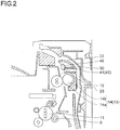
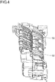
- the transport guide member 30 is constituted of a plurality of plate-like guide rib 31 disposed at a predetermined interval in the width direction of the paper sheet P (which is perpendicular to the sheet transport direction and is perpendicular to the paper plane of FIG. 2 ) so as to guide the paper sheet P, a guide curved surface portion 32 that extends in the width direction of the paper sheet P and is formed integrally with the plurality of guide ribs 31 (see also FIG. 4 ), and the like.
- the guide ribs 31 constitute a part of the sheet transport path 18, and the guide curved surface portion 32 constitute a part of the double-sided transport path 22.
- the transport guide member 30 includes a base portion (guide curved surface portion 32) and the guide ribs 31 standing on the base portion.
- One surface on which the guide ribs 31 are disposed guides the paper sheet P on which the image is formed in the image forming portions Pa to Pd to the discharge roller pair 19 (discharge portion), and other surface formed on the backside of the base portion guides the paper sheet P transported reversely from the discharge roller pair 19 to the double-sided transport path 22.
- the sheet transport path 18 is provided with a detection mechanism 40 for detecting presence or absence of the paper sheet P, which is disposed in a vicinity of the upper side of the fixing roller pair 14 (on the downstream side in the sheet transport direction).
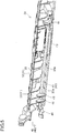
- the detection mechanism 40 is disposed only on one side (the left side in FIG. 3 ) from the middle of a paper sheet passing region.
- the detection mechanism 40 includes an actuator portion 41 extending in the width direction of the paper sheet P so as to swing when abutting the paper sheet P, a sensor portion 42 constituted of a PI sensor or the like configured to detect swinging of the actuator portion 41.
- a link member (not shown) or the like that is driven to move (swing, for example) by swinging of a swing portion 45 described later of the actuator portion 41
- the sensor portion 42 is configured to detect swinging of the actuator portion 41 by detecting the movement of the link member.
- the sensor portion 42 may be configured to detect directly the swinging of the swing portion 45 described later of the actuator portion 41.
- a notch portion 33a through which a shaft portion 43 described later of the actuator portion 41 penetrates is formed in a first guide ribs 33 disposed on the left side (on the one side from the middle of the paper sheet passing region) among the plurality of guide ribs 31.
- This notch portion 33a is formed in a front part of the first guide ribs 33 (a part constituting the sheet transport path 18). Further, a most part of the actuator portion 41 is disposed inside the transport guide member 30.
- the actuator portion 41 includes the shaft portion 43 that extends in the width direction of the paper sheet P and is pivoted by the transport guide member 30 in a swingable manner, a detection portion 44 disposed to protrude outward in the radial direction from the shaft portion 43 so as to swing about the shaft portion 43 in the transport direction when abutting the paper sheet P, and the swing portion 45 disposed on the shaft portion 43 so as to swing about the shaft portion 43 in the transport direction.
- the shaft portion 43 extends to one side (the left side in FIG. 3 ) from the middle of the paper sheet passing region (the middle of the transport guide member 30) and is formed to the outside of the paper sheet passing region.
- the detection portion 44 is fixed to the other end of the shaft portion 43 (the right end in FIG. 3 ), is disposed in the middle of the paper sheet passing region, and is formed to protrude into the sheet transport path 18.
- the swing portion 45 is disposed outside the paper sheet passing region and is also fixed to one end of the shaft portion 43 (the left end in FIG. 3 ).
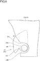
- the shaft portion 43 is provided with a second guide rib 46 that closes an opening (overlaps an opening) of the notch portion 33a viewed from an axis direction of the shaft portion 43.
- the second guide rib 46 is disposed to protrude outward in the radial direction from the shaft portion 43 so as to correspond to at least one of the first guide ribs 33 in which the notch portion 33a is formed, and hence closes the opening of the corresponding notch portion 33a.
- the second guide rib 46 is disposed in a position of the shaft portion 43 closer to an outside of the paper sheet passing region. Specifically, the second guide rib 46 is disposed in a position inside and end of the paper sheet passing region.
- the second guide rib 46 is disposed in a position where the curled front edge of the paper sheet P (the end in the width direction) can be easily caught.
- the second guide rib 46 is fixed to the shaft portion 43 and swings integrally with the shaft portion 43.
- the paper sheet P is transported from a lower side to an upper side.
- the second guide rib 46 closes an opening 33b of the notch portion 33a on the lower side of the shaft portion 43 (on the upstream side in the sheet transport direction).
- the paper sheet P abuts the detection portion 44 so that the actuator portion 41 swings in a clockwise direction in FIG. 6 (as illustrated in FIG. 7 and FIG.
- the second guide rib 46 closes an opening 33c of the notch portion 33a on the downstream side in the sheet transport direction (upper side) of the shaft portion 43.
- an angle ⁇ between a part of the first guide rib 33 on the upper side (on the downstream side in the sheet transport direction) and the second guide rib 46 is an obtuse angle. In this way, there is a smooth connection from the second guide rib 46 to the first guide rib 33 so that it is possible to prevent the paper sheet P from being caught by an intersection between the second guide rib 46 and the first guide rib 33.
- the second guide rib 46 may close the opening 33c of the notch portion 33a on the upper side (on the downstream side in the sheet transport direction) of the shaft portion 43.
- the angle ⁇ between the upper side part of the first guide rib 33 and the second guide rib 46 be an obtuse angle.
- a sheet abutting portion of the second guide rib 46 is disposed on the lower side (on the upstream side in the sheet transport direction) of the sheet abutting portion (the lowest part) of the detection portion 44 viewed from the axis direction of the shaft portion 43. In this way, the second guide rib 46 abuts the transported paper sheet P earlier than the detection portion 44.
- the actuator portion 41 swings in the clockwise direction in FIG. 6 .
- the second guide rib 46 keeps the paper sheet P away from the notch portion 33a and guides the paper sheet P to the upper side (on the downstream side in the sheet transport direction).
- the sensor portion 42 detects swinging of the actuator portion 41 so that presence of the paper sheet P is detected by the detection mechanism 40.
- the second guide rib 46 closes the opening 33c of the notch portion 33a on the upper side of the shaft portion 43. Therefore, the paper sheet P does not enter the notch portion 33a.
- a weight of the detection portion 44 and the like causes a downward moment to act on a rotation shaft so that the actuator portion 41 swings in the opposite direction (in the counterclockwise direction in FIG. 8 ) to return to the original state (a standby state illustrated in FIG. 5 and FIG. 6 ).
- the swing portion 45 also swings in the opposite direction (in the counterclockwise direction in FIG. 8 ) so that the sensor portion 42 detects swinging of the actuator portion 41 in the opposite direction, and hence absence of the paper sheet P is detected by the detection mechanism 40.
- the notch portion 33a through which the shaft portion 43 of the actuator portion 41 penetrates is formed in the first guide rib 33 as described above.
- the shaft portion 43 of the actuator portion 41 can be disposed in the transport guide member 30.
- the actuator portion 41 can be easily disposed in the position to abut the paper sheet P and not to prevent transportation of the paper sheet P.
- the second guide rib 46 closing the opening of the notch portion 33a of the first guide rib 33 viewed from the axis direction of the shaft portion 43.
- the second guide rib 46 closes the opening 33b of the notch portion 33a on the lower side (on the upstream side in the sheet transport direction) of the shaft portion 43. In this way, it is possible to prevent the paper sheet P from entering the opening 33b of the notch portion 33a on the lower side of the shaft portion 43.
- the second guide rib 46 closes the opening 33c of the notch portion 33a on the upper side of the shaft portion 43. In this way, it is possible to prevent the paper sheet P from entering the opening 33c of the notch portion 33a on the upper side of the shaft portion 43.
- the angle ⁇ between the part of the first guide rib 33 on the upper side of the shaft portion 43 and the second guide rib 46 is an obtuse angle. In this way, it is possible to prevent the front end of the paper sheet P from entering the intersection between the part of the first guide rib 33 on the upper side of the shaft portion 43 and the second guide rib 46 to be hardly able to escape. Therefore, it is possible to further prevent occurrence of jamming of the paper sheet P.
- the second guide rib 46 is formed to swing about the shaft portion 43. In this way, when the second guide rib 46 swings, the paper sheet P can be guided to the upper side (on the downstream side in the sheet transport direction). Therefore, it is possible to further prevent occurrence of jamming of the paper sheet P.
- the second guide rib 46 abuts the paper sheet P earlier than the detection portion 44 (or simultaneously with the detection portion 44). In this way, it is possible to prevent the actuator portion 41 from swinging before the paper sheet P abuts the second guide rib 46. Therefore, it is possible to prevent the opening 33b of the notch portion 33a on the lower side of the shaft portion 43 from being opened so that the paper sheet P enters the opened part. In this way, it is possible to further prevent occurrence of jamming of the paper sheet P.
- the second guide rib 46 is disposed at a position of the shaft portion 43 closer to the outside of the paper sheet passing region (in a vicinity of inside of a position where the end in the width direction of a large size paper sheet passes).
- the end of the paper sheet P is apt to curl when the size thereof increases. Therefore, the curled front edge of the paper sheet P is apt to enter the notch portion 33a in a position close to the outside of the paper sheet passing region. Therefore, it is particularly effective to dispose the second guide rib 46 at the position on the shaft portion 43 close to the outside of the paper sheet passing region.
- the transport guide member 30 and the detection mechanism 40 are disposed on the downstream side in the sheet transport direction of the fixing device 13.
- the paper sheet P after passing the fixing device 13 is apt to be curled by heat and pressure in the fixing process, and hence jamming of the paper sheet P is apt to occur in the downstream in the sheet transport direction of the fixing device 13. Therefore, it is particularly effective to dispose the transport guide member 30 and the detection mechanism 40 on the downstream side in the sheet transport direction of the fixing device 13 so as to prevent occurrence of jamming of the paper sheet P after passing the fixing device 13.
- the present disclosure is applied to the color printer, but the present disclosure is not limited to this example. It is needless to say that the present disclosure can be applied to various image forming apparatuses such as a monochrome printer, a color copier, a monochrome copier, a digital multifunction peripheral, and a facsimile machine, which include a transport guide member for guiding a recording medium, and a detection mechanism for detecting presence or absence of the recording medium.
- the present disclosure is applied to the transport guide member and the detection mechanism disposed on the downstream side in the sheet transport direction of the fixing device.
- the present disclosure can be applied to the transport guide member and the detection mechanism disposed at a part of the fixing device other than the downstream side in the sheet transport direction.
- the present disclosure is not limited to this example.
- this structure it is possible to prevent occurrence of jamming of not only a large size paper sheet P but also a small size paper sheet P.
- the present disclosure is not limited to this example.
- the second guide rib may not swing integrally with the shaft portion.
Landscapes
- Physics & Mathematics (AREA)
- General Physics & Mathematics (AREA)
- Engineering & Computer Science (AREA)
- Multimedia (AREA)
- Signal Processing (AREA)
- Feeding Of Articles By Means Other Than Belts Or Rollers (AREA)
- Controlling Sheets Or Webs (AREA)
- Paper Feeding For Electrophotography (AREA)
- Electrophotography Configuration And Component (AREA)
Claims (10)
- Bilderzeugungsvorrichtung (100), die aufweist:eine Transportbahn (18), in der das Aufzeichnungsmedium (P) läuft;ein Transportelement, das in der Transportbahn (18) angeordnet ist, zum Transportieren des Aufzeichnungsmediums (P),ein Transport-Führungselement (30), das die Transportbahn (18) bildet, zum Führen des Aufzeichnungsmediums (P) undeinen Erfassungsmechanismus (40), der in der Transportbahn (18) angeordnet ist, zum Erfassen des Vorliegens oder Nichtvorliegens des Aufzeichnungsmediums (P),wobei der Erfassungsmechanismus (40) einen Aktuatorteil (41), der so gestaltet ist, dass er bei Anstoßen des Aufzeichnungsmediums (P) schwenkt, und einen Sensorteil (42) beinhaltet, der so gestaltet ist, dass er das Schwenken des Aktuatorteils (41) erfasst,wobei der Aktuatorteil (41) einen Wellenteil (43), der sich in der Breitenrichtung des Aufzeichnungsmediums (P) erstreckt, die orthogonal zu der Transportrichtung des Aufzeichnungsmediums (P) ist, und einen Erfassungsteil (44) aufweist, der so angeordnet ist, dass er in der Radialrichtung von dem Wellenteil (43) nach außen vorsteht, so dass er bei Anstoßen des Aufzeichnungsmediums (P) in einer Transportrichtung um den Wellenteil (43) schwenkt,das Transport-Führungselement (30) ein Unterteil (32) und eine Vielzahl von ersten Führungsrippen (33) aufweist, die sich in einem vorgegebenen Abstand in der Breitenrichtung des Aufzeichnungsmediums (P) befinden, um das Aufzeichnungsmedium (P) zu führen,die ersten Führungsrippen (33) mit einem Aussparungsabschnitt (33a) versehen sind, in dem der Wellenteil (43) des Aktuatorteils (41) zu liegen kommt,dadurch gekennzeichnet, dassder Wellenteil (43) mit einer zweiten Führungsrippe (46) versehen ist, die an einer Stelle, die mindestens einer der ersten Führungsrippen (33) entspricht, in denen der Aussparungsabschnitt (33a) ausgebildet ist, so angeordnet ist, dass sie in der Radialrichtung von dem Wellenteil (43) nach außen vorsteht, unddie zweite Führungsrippe (46) so angeordnet ist, dass sie eine Öffnung (33b, 33c) des entsprechenden Aussparungsabschnitts (33a), gesehen aus der Achsenrichtung des Wellenteils (43), schließt, bevor das Aufzeichnungsmedium (P) an den Erfassungsteil (44) anstößt, um dadurch zu verhindern, dass das Aufzeichnungsmedium (P) in den Aussparungsabschnitt (33a) eintritt.
- Bilderzeugungsvorrichtung (100) nach Anspruch 1, bei der in einem Stadium, bevor das Aufzeichnungsmedium (P) an den Erfassungsteil (44) anstößt, die zweite Führungsrippe (46) die Öffnung (33b) des Aussparungsabschnitts (33a), gesehen aus der Achsenrichtung des Wellenteils (43), auf der Stromaufseite des Wellenteils (43) in der Transportrichtung des Aufzeichnungsmediums schließt.
- Bilderzeugungsvorrichtung (100) nach Anspruch 1 oder 2, bei der in einem Stadium, in dem das Aufzeichnungsmedium (P) an den Erfassungsteil (44) anstößt, so dass der Aktuatorteil (41) schwenkt, die zweite Führungsrippe (46) die Öffnung (33c) des Aussparungsabschnitts (33a), gesehen aus der Achsenrichtung des Wellenteils (43), auf der Stromabseite des Wellenteils (43) in der Transportrichtung des Aufzeichnungsmediums schließt.
- Bilderzeugungsvorrichtung (100) nach Anspruch 3, bei der in einem Stadium, in dem das Aufzeichnungsmedium (P) an den Erfassungsteil (44) anstößt, so dass der Aktuatorteil (41) schwenkt, ein Winkel (θ), gesehen aus der Achsenrichtung des Wellenteils (43), unter dem die erste Führungsrippe (33) und die zweite Führungsrippe (46) einander auf der Stromabseite in der Transportrichtung des Aufzeichnungsmediums kreuzen, ein stumpfer Winkel ist.
- Bilderzeugungsvorrichtung (100) nach einem der Ansprüche 1 bis 4, bei der, gesehen aus der Achsenrichtung des Wellenteils (43), ein Abschnitt der zweiten Führungsrippe (46), an dem das Aufzeichnungsmedium anstößt, auf der Stromaufseite eines Abschnitts des Erfassungsteils (44), an dem das Aufzeichnungsmedium anstößt, in der Transportrichtung vorgesehen ist.
- Bilderzeugungsvorrichtung (100) nach Anspruch 5, bei der das transportierte Aufzeichnungsmedium (P) früher an der zweiten Führungsrippe (46) anstößt als an dem Erfassungsteil (44).
- Bilderzeugungsvorrichtung (100) nach einem der Ansprüche 1 bis 6, bei der die zweite Führungsrippe (46) in einem Bereich des Wellenteils (43) angeordnet ist, in dem ein Ende des Aufzeichnungsmediums (P) in der Breitenrichtung durchläuft.
- Bilderzeugungsvorrichtung (100) nach Anspruch 7, bei der die zweite Führungsrippe (46) eine Vielzahl von zweiten Führungsrippen (46) umfasst, die so angeordnet sind, dass sie jeweils unterschiedlichen Enden des Aufzeichnungsmediums (P) in der Breitenrichtung entsprechen.
- Bilderzeugungsvorrichtung (100) nach einem der Ansprüche 1 bis 8, die ferner eine Fixiervorrichtung (13) zum Fixieren eines Tonerbildes auf dem Aufzeichnungsmedium (P) aufweist, wobei das Transport-Führungselement (30) und der Erfassungsmechanismus (40) auf der Stromabseite in der Transportrichtung des Aufzeichnungsmediums der Fixiervorrichtung (13) angeordnet sind.
- Bilderzeugungsvorrichtung (100) nach einem der Ansprüche 1 bis 8, bei der das Transport-Führungselement (30) auf der Stromabseite in der Transportrichtung eines Bilderzeugungsabschnitts (Pa-Pd) angeordnet ist, eine Fläche der ersten Führungsrippe (33) das Aufzeichnungsmedium (P), auf dem in dem Bilderzeugungsabschnitt (Pa-Pd) ein Bild erzeugt ist, zu einem Ausgabeabschnitt (19) führt und die andere Fläche, die auf der Rückseite des Unterteils (32) gebildet ist, das Aufzeichnungsmedium (P) führt, das von dem Ausgabeabschnitt (19) in umgekehrter Richtung zu einer Doppelseiten-Transportbahn (22) transportiert wird.
Priority Applications (1)
| Application Number | Priority Date | Filing Date | Title |
|---|---|---|---|
| EP18168521.5A EP3392716B1 (de) | 2013-05-27 | 2014-05-21 | Bilderzeugungsvorrichtung |
Applications Claiming Priority (1)
| Application Number | Priority Date | Filing Date | Title |
|---|---|---|---|
| JP2013110694A JP5796910B2 (ja) | 2013-05-27 | 2013-05-27 | 画像形成装置 |
Related Child Applications (2)
| Application Number | Title | Priority Date | Filing Date |
|---|---|---|---|
| EP18168521.5A Division EP3392716B1 (de) | 2013-05-27 | 2014-05-21 | Bilderzeugungsvorrichtung |
| EP18168521.5A Division-Into EP3392716B1 (de) | 2013-05-27 | 2014-05-21 | Bilderzeugungsvorrichtung |
Publications (2)
| Publication Number | Publication Date |
|---|---|
| EP2808740A1 EP2808740A1 (de) | 2014-12-03 |
| EP2808740B1 true EP2808740B1 (de) | 2018-06-20 |
Family
ID=50732985
Family Applications (2)
| Application Number | Title | Priority Date | Filing Date |
|---|---|---|---|
| EP18168521.5A Active EP3392716B1 (de) | 2013-05-27 | 2014-05-21 | Bilderzeugungsvorrichtung |
| EP14169360.6A Active EP2808740B1 (de) | 2013-05-27 | 2014-05-21 | Bilderzeugungsvorrichtung |
Family Applications Before (1)
| Application Number | Title | Priority Date | Filing Date |
|---|---|---|---|
| EP18168521.5A Active EP3392716B1 (de) | 2013-05-27 | 2014-05-21 | Bilderzeugungsvorrichtung |
Country Status (4)
| Country | Link |
|---|---|
| US (1) | US8928898B2 (de) |
| EP (2) | EP3392716B1 (de) |
| JP (1) | JP5796910B2 (de) |
| CN (1) | CN104181791B (de) |
Families Citing this family (2)
| Publication number | Priority date | Publication date | Assignee | Title |
|---|---|---|---|---|
| JP2024165186A (ja) * | 2023-05-16 | 2024-11-28 | 京セラドキュメントソリューションズ株式会社 | 用紙搬送装置、及び画像形成装置 |
| JP2025003359A (ja) * | 2023-06-22 | 2025-01-09 | 京セラドキュメントソリューションズ株式会社 | 定着装置及び画像形成装置 |
Family Cites Families (8)
| Publication number | Priority date | Publication date | Assignee | Title |
|---|---|---|---|---|
| US5083761A (en) * | 1988-08-31 | 1992-01-28 | Minolta Camera Kabushiki Kaisha | Sheet storing apparatus for sheets ejected from a copying machine |
| JP4323973B2 (ja) * | 2004-02-04 | 2009-09-02 | キヤノン株式会社 | シート給送装置及びこれを備えた画像形成装置並びに画像読取装置 |
| JP4715619B2 (ja) | 2006-04-27 | 2011-07-06 | 富士ゼロックス株式会社 | 定着器及び画像形成装置 |
| JP4999713B2 (ja) * | 2007-01-26 | 2012-08-15 | キヤノン株式会社 | シート搬送装置及び画像形成装置 |
| WO2010083310A2 (en) | 2009-01-14 | 2010-07-22 | Dow Agrosciences Llc | Fungicidal compositions including hydrazone derivatives and copper |
| JP4752938B2 (ja) * | 2009-03-27 | 2011-08-17 | 富士ゼロックス株式会社 | 記録媒体搬送方向切り換え機構、及びこれを備えた定着装置並びに画像形成装置 |
| JP2011011828A (ja) | 2009-06-30 | 2011-01-20 | Konica Minolta Business Technologies Inc | 画像形成装置 |
| JP5741119B2 (ja) * | 2011-03-28 | 2015-07-01 | 富士ゼロックス株式会社 | 用紙搬送装置および画像形成装置 |
-
2013
- 2013-05-27 JP JP2013110694A patent/JP5796910B2/ja active Active
-
2014
- 2014-05-20 US US14/283,146 patent/US8928898B2/en active Active
- 2014-05-21 EP EP18168521.5A patent/EP3392716B1/de active Active
- 2014-05-21 EP EP14169360.6A patent/EP2808740B1/de active Active
- 2014-05-23 CN CN201410222086.2A patent/CN104181791B/zh active Active
Non-Patent Citations (1)
| Title |
|---|
| None * |
Also Published As
| Publication number | Publication date |
|---|---|
| CN104181791B (zh) | 2016-11-23 |
| EP3392716B1 (de) | 2019-12-25 |
| CN104181791A (zh) | 2014-12-03 |
| US8928898B2 (en) | 2015-01-06 |
| EP2808740A1 (de) | 2014-12-03 |
| EP3392716A1 (de) | 2018-10-24 |
| US20140347684A1 (en) | 2014-11-27 |
| JP5796910B2 (ja) | 2015-10-21 |
| JP2014227289A (ja) | 2014-12-08 |
Similar Documents
| Publication | Publication Date | Title |
|---|---|---|
| JP4038328B2 (ja) | 画像形成装置、転写材搬送方法及び転写装置 | |
| JP5482372B2 (ja) | 画像形成装置 | |
| JP2010197458A (ja) | 画像形成装置 | |
| JP5505788B2 (ja) | シート搬送装置および画像形成装置 | |
| JP2011081164A (ja) | 画像形成装置 | |
| JP5754625B2 (ja) | 画像読取装置および画像形成装置 | |
| JP5495123B2 (ja) | シート搬送装置及び画像形成装置 | |
| EP3392716B1 (de) | Bilderzeugungsvorrichtung | |
| US20110236082A1 (en) | Fixing device and image forming apparatus | |
| JP2012020845A (ja) | シート排出装置及び画像形成装置 | |
| US11964843B2 (en) | Transport device and image forming apparatus | |
| JP5703278B2 (ja) | 画像形成装置 | |
| JP6992676B2 (ja) | 定着装置および画像形成装置 | |
| JP6146919B2 (ja) | 画像形成装置 | |
| JP6358218B2 (ja) | 画像形成装置 | |
| JP2013242596A (ja) | 画像形成装置 | |
| JP5341226B2 (ja) | 画像形成装置 | |
| JP4811456B2 (ja) | 検知装置及びこれを備えた画像形成装置 | |
| JP6601050B2 (ja) | シート搬送装置及び画像形成装置 | |
| JP5660287B2 (ja) | 記録媒体搬送装置及び画像形成装置 | |
| JP2024136485A (ja) | 画像形成装置 | |
| JP2009116260A (ja) | 画像形成装置 | |
| JP5707890B2 (ja) | 画像形成装置 | |
| JP5943235B2 (ja) | 画像形成装置 | |
| JP2005221777A (ja) | 画像形成装置 |
Legal Events
| Date | Code | Title | Description |
|---|---|---|---|
| PUAI | Public reference made under article 153(3) epc to a published international application that has entered the european phase |
Free format text: ORIGINAL CODE: 0009012 |
|
| 17P | Request for examination filed |
Effective date: 20140521 |
|
| AK | Designated contracting states |
Kind code of ref document: A1 Designated state(s): AL AT BE BG CH CY CZ DE DK EE ES FI FR GB GR HR HU IE IS IT LI LT LU LV MC MK MT NL NO PL PT RO RS SE SI SK SM TR |
|
| AX | Request for extension of the european patent |
Extension state: BA ME |
|
| R17P | Request for examination filed (corrected) |
Effective date: 20150603 |
|
| RBV | Designated contracting states (corrected) |
Designated state(s): AL AT BE BG CH CY CZ DE DK EE ES FI FR GB GR HR HU IE IS IT LI LT LU LV MC MK MT NL NO PL PT RO RS SE SI SK SM TR |
|
| GRAP | Despatch of communication of intention to grant a patent |
Free format text: ORIGINAL CODE: EPIDOSNIGR1 |
|
| STAA | Information on the status of an ep patent application or granted ep patent |
Free format text: STATUS: GRANT OF PATENT IS INTENDED |
|
| INTG | Intention to grant announced |
Effective date: 20171219 |
|
| GRAS | Grant fee paid |
Free format text: ORIGINAL CODE: EPIDOSNIGR3 |
|
| GRAA | (expected) grant |
Free format text: ORIGINAL CODE: 0009210 |
|
| STAA | Information on the status of an ep patent application or granted ep patent |
Free format text: STATUS: THE PATENT HAS BEEN GRANTED |
|
| AK | Designated contracting states |
Kind code of ref document: B1 Designated state(s): AL AT BE BG CH CY CZ DE DK EE ES FI FR GB GR HR HU IE IS IT LI LT LU LV MC MK MT NL NO PL PT RO RS SE SI SK SM TR |
|
| REG | Reference to a national code |
Ref country code: GB Ref legal event code: FG4D |
|
| REG | Reference to a national code |
Ref country code: IE Ref legal event code: FG4D |
|
| REG | Reference to a national code |
Ref country code: DE Ref legal event code: R096 Ref document number: 602014027223 Country of ref document: DE |
|
| REG | Reference to a national code |
Ref country code: AT Ref legal event code: REF Ref document number: 1011036 Country of ref document: AT Kind code of ref document: T Effective date: 20180715 |
|
| REG | Reference to a national code |
Ref country code: NL Ref legal event code: MP Effective date: 20180620 |
|
| PG25 | Lapsed in a contracting state [announced via postgrant information from national office to epo] |
Ref country code: NO Free format text: LAPSE BECAUSE OF FAILURE TO SUBMIT A TRANSLATION OF THE DESCRIPTION OR TO PAY THE FEE WITHIN THE PRESCRIBED TIME-LIMIT Effective date: 20180920 Ref country code: LT Free format text: LAPSE BECAUSE OF FAILURE TO SUBMIT A TRANSLATION OF THE DESCRIPTION OR TO PAY THE FEE WITHIN THE PRESCRIBED TIME-LIMIT Effective date: 20180620 Ref country code: SE Free format text: LAPSE BECAUSE OF FAILURE TO SUBMIT A TRANSLATION OF THE DESCRIPTION OR TO PAY THE FEE WITHIN THE PRESCRIBED TIME-LIMIT Effective date: 20180620 Ref country code: FI Free format text: LAPSE BECAUSE OF FAILURE TO SUBMIT A TRANSLATION OF THE DESCRIPTION OR TO PAY THE FEE WITHIN THE PRESCRIBED TIME-LIMIT Effective date: 20180620 Ref country code: BG Free format text: LAPSE BECAUSE OF FAILURE TO SUBMIT A TRANSLATION OF THE DESCRIPTION OR TO PAY THE FEE WITHIN THE PRESCRIBED TIME-LIMIT Effective date: 20180920 |
|
| REG | Reference to a national code |
Ref country code: LT Ref legal event code: MG4D |
|
| PG25 | Lapsed in a contracting state [announced via postgrant information from national office to epo] |
Ref country code: HR Free format text: LAPSE BECAUSE OF FAILURE TO SUBMIT A TRANSLATION OF THE DESCRIPTION OR TO PAY THE FEE WITHIN THE PRESCRIBED TIME-LIMIT Effective date: 20180620 Ref country code: RS Free format text: LAPSE BECAUSE OF FAILURE TO SUBMIT A TRANSLATION OF THE DESCRIPTION OR TO PAY THE FEE WITHIN THE PRESCRIBED TIME-LIMIT Effective date: 20180620 Ref country code: LV Free format text: LAPSE BECAUSE OF FAILURE TO SUBMIT A TRANSLATION OF THE DESCRIPTION OR TO PAY THE FEE WITHIN THE PRESCRIBED TIME-LIMIT Effective date: 20180620 Ref country code: GR Free format text: LAPSE BECAUSE OF FAILURE TO SUBMIT A TRANSLATION OF THE DESCRIPTION OR TO PAY THE FEE WITHIN THE PRESCRIBED TIME-LIMIT Effective date: 20180921 |
|
| REG | Reference to a national code |
Ref country code: AT Ref legal event code: MK05 Ref document number: 1011036 Country of ref document: AT Kind code of ref document: T Effective date: 20180620 |
|
| PG25 | Lapsed in a contracting state [announced via postgrant information from national office to epo] |
Ref country code: NL Free format text: LAPSE BECAUSE OF FAILURE TO SUBMIT A TRANSLATION OF THE DESCRIPTION OR TO PAY THE FEE WITHIN THE PRESCRIBED TIME-LIMIT Effective date: 20180620 |
|
| PG25 | Lapsed in a contracting state [announced via postgrant information from national office to epo] |
Ref country code: EE Free format text: LAPSE BECAUSE OF FAILURE TO SUBMIT A TRANSLATION OF THE DESCRIPTION OR TO PAY THE FEE WITHIN THE PRESCRIBED TIME-LIMIT Effective date: 20180620 Ref country code: PL Free format text: LAPSE BECAUSE OF FAILURE TO SUBMIT A TRANSLATION OF THE DESCRIPTION OR TO PAY THE FEE WITHIN THE PRESCRIBED TIME-LIMIT Effective date: 20180620 Ref country code: SK Free format text: LAPSE BECAUSE OF FAILURE TO SUBMIT A TRANSLATION OF THE DESCRIPTION OR TO PAY THE FEE WITHIN THE PRESCRIBED TIME-LIMIT Effective date: 20180620 Ref country code: CZ Free format text: LAPSE BECAUSE OF FAILURE TO SUBMIT A TRANSLATION OF THE DESCRIPTION OR TO PAY THE FEE WITHIN THE PRESCRIBED TIME-LIMIT Effective date: 20180620 Ref country code: IS Free format text: LAPSE BECAUSE OF FAILURE TO SUBMIT A TRANSLATION OF THE DESCRIPTION OR TO PAY THE FEE WITHIN THE PRESCRIBED TIME-LIMIT Effective date: 20181020 Ref country code: AT Free format text: LAPSE BECAUSE OF FAILURE TO SUBMIT A TRANSLATION OF THE DESCRIPTION OR TO PAY THE FEE WITHIN THE PRESCRIBED TIME-LIMIT Effective date: 20180620 Ref country code: RO Free format text: LAPSE BECAUSE OF FAILURE TO SUBMIT A TRANSLATION OF THE DESCRIPTION OR TO PAY THE FEE WITHIN THE PRESCRIBED TIME-LIMIT Effective date: 20180620 |
|
| PG25 | Lapsed in a contracting state [announced via postgrant information from national office to epo] |
Ref country code: ES Free format text: LAPSE BECAUSE OF FAILURE TO SUBMIT A TRANSLATION OF THE DESCRIPTION OR TO PAY THE FEE WITHIN THE PRESCRIBED TIME-LIMIT Effective date: 20180620 Ref country code: SM Free format text: LAPSE BECAUSE OF FAILURE TO SUBMIT A TRANSLATION OF THE DESCRIPTION OR TO PAY THE FEE WITHIN THE PRESCRIBED TIME-LIMIT Effective date: 20180620 Ref country code: IT Free format text: LAPSE BECAUSE OF FAILURE TO SUBMIT A TRANSLATION OF THE DESCRIPTION OR TO PAY THE FEE WITHIN THE PRESCRIBED TIME-LIMIT Effective date: 20180620 |
|
| REG | Reference to a national code |
Ref country code: DE Ref legal event code: R097 Ref document number: 602014027223 Country of ref document: DE |
|
| PLBE | No opposition filed within time limit |
Free format text: ORIGINAL CODE: 0009261 |
|
| STAA | Information on the status of an ep patent application or granted ep patent |
Free format text: STATUS: NO OPPOSITION FILED WITHIN TIME LIMIT |
|
| 26N | No opposition filed |
Effective date: 20190321 |
|
| PG25 | Lapsed in a contracting state [announced via postgrant information from national office to epo] |
Ref country code: DK Free format text: LAPSE BECAUSE OF FAILURE TO SUBMIT A TRANSLATION OF THE DESCRIPTION OR TO PAY THE FEE WITHIN THE PRESCRIBED TIME-LIMIT Effective date: 20180620 |
|
| PG25 | Lapsed in a contracting state [announced via postgrant information from national office to epo] |
Ref country code: SI Free format text: LAPSE BECAUSE OF FAILURE TO SUBMIT A TRANSLATION OF THE DESCRIPTION OR TO PAY THE FEE WITHIN THE PRESCRIBED TIME-LIMIT Effective date: 20180620 |
|
| PG25 | Lapsed in a contracting state [announced via postgrant information from national office to epo] |
Ref country code: AL Free format text: LAPSE BECAUSE OF FAILURE TO SUBMIT A TRANSLATION OF THE DESCRIPTION OR TO PAY THE FEE WITHIN THE PRESCRIBED TIME-LIMIT Effective date: 20180620 |
|
| REG | Reference to a national code |
Ref country code: CH Ref legal event code: PL |
|
| PG25 | Lapsed in a contracting state [announced via postgrant information from national office to epo] |
Ref country code: CH Free format text: LAPSE BECAUSE OF NON-PAYMENT OF DUE FEES Effective date: 20190531 Ref country code: LI Free format text: LAPSE BECAUSE OF NON-PAYMENT OF DUE FEES Effective date: 20190531 Ref country code: MC Free format text: LAPSE BECAUSE OF FAILURE TO SUBMIT A TRANSLATION OF THE DESCRIPTION OR TO PAY THE FEE WITHIN THE PRESCRIBED TIME-LIMIT Effective date: 20180620 |
|
| REG | Reference to a national code |
Ref country code: BE Ref legal event code: MM Effective date: 20190531 |
|
| PG25 | Lapsed in a contracting state [announced via postgrant information from national office to epo] |
Ref country code: LU Free format text: LAPSE BECAUSE OF NON-PAYMENT OF DUE FEES Effective date: 20190521 |
|
| PG25 | Lapsed in a contracting state [announced via postgrant information from national office to epo] |
Ref country code: TR Free format text: LAPSE BECAUSE OF FAILURE TO SUBMIT A TRANSLATION OF THE DESCRIPTION OR TO PAY THE FEE WITHIN THE PRESCRIBED TIME-LIMIT Effective date: 20180620 |
|
| PG25 | Lapsed in a contracting state [announced via postgrant information from national office to epo] |
Ref country code: IE Free format text: LAPSE BECAUSE OF NON-PAYMENT OF DUE FEES Effective date: 20190521 |
|
| PG25 | Lapsed in a contracting state [announced via postgrant information from national office to epo] |
Ref country code: BE Free format text: LAPSE BECAUSE OF NON-PAYMENT OF DUE FEES Effective date: 20190531 |
|
| PG25 | Lapsed in a contracting state [announced via postgrant information from national office to epo] |
Ref country code: PT Free format text: LAPSE BECAUSE OF FAILURE TO SUBMIT A TRANSLATION OF THE DESCRIPTION OR TO PAY THE FEE WITHIN THE PRESCRIBED TIME-LIMIT Effective date: 20181022 |
|
| PG25 | Lapsed in a contracting state [announced via postgrant information from national office to epo] |
Ref country code: CY Free format text: LAPSE BECAUSE OF FAILURE TO SUBMIT A TRANSLATION OF THE DESCRIPTION OR TO PAY THE FEE WITHIN THE PRESCRIBED TIME-LIMIT Effective date: 20180620 |
|
| PG25 | Lapsed in a contracting state [announced via postgrant information from national office to epo] |
Ref country code: HU Free format text: LAPSE BECAUSE OF FAILURE TO SUBMIT A TRANSLATION OF THE DESCRIPTION OR TO PAY THE FEE WITHIN THE PRESCRIBED TIME-LIMIT; INVALID AB INITIO Effective date: 20140521 Ref country code: MT Free format text: LAPSE BECAUSE OF FAILURE TO SUBMIT A TRANSLATION OF THE DESCRIPTION OR TO PAY THE FEE WITHIN THE PRESCRIBED TIME-LIMIT Effective date: 20180620 |
|
| PG25 | Lapsed in a contracting state [announced via postgrant information from national office to epo] |
Ref country code: MK Free format text: LAPSE BECAUSE OF FAILURE TO SUBMIT A TRANSLATION OF THE DESCRIPTION OR TO PAY THE FEE WITHIN THE PRESCRIBED TIME-LIMIT Effective date: 20180620 |
|
| P01 | Opt-out of the competence of the unified patent court (upc) registered |
Effective date: 20230420 |
|
| PGFP | Annual fee paid to national office [announced via postgrant information from national office to epo] |
Ref country code: DE Payment date: 20250423 Year of fee payment: 12 |
|
| PGFP | Annual fee paid to national office [announced via postgrant information from national office to epo] |
Ref country code: GB Payment date: 20250423 Year of fee payment: 12 |
|
| PGFP | Annual fee paid to national office [announced via postgrant information from national office to epo] |
Ref country code: FR Payment date: 20250423 Year of fee payment: 12 |