EP2806442A1 - Schalter und Steuerverfahren dafür - Google Patents
Schalter und Steuerverfahren dafür Download PDFInfo
- Publication number
- EP2806442A1 EP2806442A1 EP20140165480 EP14165480A EP2806442A1 EP 2806442 A1 EP2806442 A1 EP 2806442A1 EP 20140165480 EP20140165480 EP 20140165480 EP 14165480 A EP14165480 A EP 14165480A EP 2806442 A1 EP2806442 A1 EP 2806442A1
- Authority
- EP
- European Patent Office
- Prior art keywords
- switch
- remote control
- contact
- operation button
- control unit
- Prior art date
- Legal status (The legal status is an assumption and is not a legal conclusion. Google has not performed a legal analysis and makes no representation as to the accuracy of the status listed.)
- Withdrawn
Links
Images


Classifications
-
- H—ELECTRICITY
- H01—ELECTRIC ELEMENTS
- H01H—ELECTRIC SWITCHES; RELAYS; SELECTORS; EMERGENCY PROTECTIVE DEVICES
- H01H3/00—Mechanisms for operating contacts
- H01H3/22—Power arrangements internal to the switch for operating the driving mechanism
-
- H—ELECTRICITY
- H01—ELECTRIC ELEMENTS
- H01H—ELECTRIC SWITCHES; RELAYS; SELECTORS; EMERGENCY PROTECTIVE DEVICES
- H01H3/00—Mechanisms for operating contacts
- H01H3/22—Power arrangements internal to the switch for operating the driving mechanism
- H01H3/26—Power arrangements internal to the switch for operating the driving mechanism using dynamo-electric motor
-
- H—ELECTRICITY
- H01—ELECTRIC ELEMENTS
- H01H—ELECTRIC SWITCHES; RELAYS; SELECTORS; EMERGENCY PROTECTIVE DEVICES
- H01H23/00—Tumbler or rocker switches, i.e. switches characterised by being operated by rocking an operating member in the form of a rocker button
- H01H23/02—Details
- H01H23/12—Movable parts; Contacts mounted thereon
- H01H23/16—Driving mechanisms
- H01H23/20—Driving mechanisms having snap action
- H01H23/205—Driving mechanisms having snap action using a compression spring between tumbler and an articulated contact plate
-
- H—ELECTRICITY
- H01—ELECTRIC ELEMENTS
- H01H—ELECTRIC SWITCHES; RELAYS; SELECTORS; EMERGENCY PROTECTIVE DEVICES
- H01H3/00—Mechanisms for operating contacts
- H01H3/32—Driving mechanisms, i.e. for transmitting driving force to the contacts
- H01H3/40—Driving mechanisms, i.e. for transmitting driving force to the contacts using friction, toothed, or screw-and-nut gearing
Definitions
- the present invention relates to a switch that can manually and remotely be operated.
- a switch that can manually and remotely be operated, is provided with a contact that closes and opens an electric circuit and a electromagnet inside a case, and a handle on the case for closing and opening the contact by an external operation, for example.
- a permanent magnet is attached to an inside of the handle while one of poles of the permanent magnet is oriented toward the electromagnet, and the direction of a current passed through the electromagnet is switched to attract and repel the permanent magnet, whereby the contact is closed and opened when the handle is operated (see Japanese Unexamined Patent Publication No. 2003-331674 ).
- an electromagnet 13 attracts and repels a permanent magnet 15 to turn a handle 14, thereby switching a switch 11.
- the permanent magnet 15 is easily broken and easily causes a breakdown.
- the handle 14 is provided with the permanent magnet 15, the weight of the handle 14 is gained to increase an inertia force. For these reasons, the handle 14 malfunctions easily due to the external vibration or impact force.
- An object of the present invention is to provide a switch in which the breakdown is hardly generated, the harsh collision noise is not generated, and the malfunction is hardly generated.
- a switch in accordance with one aspect of the present invention, includes a movable touch piece configured to be turned by manual operation of an operation button, a movable contact that is provided in the movable touch piece and configured to be brought into contact with and separated from a fixed contact to close and open a contact, and a remote control unit configured to be able to operate the operation button by remote control.
- the remote control unit includes a stepping motor and a transmission member configured to transmit turning action of the stepping motor to the operation button to close and open the contact.
- the switch of the present invention is free from the breakage of the permanent magnet, and the breakdown is hardly generated.
- the operation button is not provided with the permanent magnet, the inertia force decreases to prevent the malfunction caused by the external impact force or vibration, and the malfunction caused by the influence of the external ferromagnetic material can also be prevented.
- the transmission member of the remote control unit may be a cam member configured to transmit the turning action of a turning shaft of the stepping motor to the operation button as turning action.
- the design and the control can be performed in various manners by the use of the cam member, and a degree of design freedom is enhanced.
- the cam member may directly be connected to the turning shaft of the stepping motor.
- the transmission member of the remote control unit may include a gear portion configured to engage a pinion connected to a turning shaft of the stepping motor.
- the movable touch piece disposed on both sides of the remote control unit may be configured to be operatable by the operation button.
- the invention also provides a method for controlling a switch including a movable touch piece configured to be turned by manual operation of an operation button, a movable contact that is provided in the movable touch piece and configured to be brought into contact with and separated from a fixed contact to close and open a contact, and a remote control unit configured to be able to operate the operation button by remote control.
- the method includes turning the operation button by a stepping motor constituting the remote control unit to close and open the contact, and reversely rotating the stepping motor to return a transmission member constituting the remote control unit to an initial position to enable manual operation.
- the switch in which the operation button can manually be operated is obtained again by returning the transmission member to the initial position.
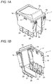
- a switch 1 of the embodiment includes a box-shaped base 10, a contact mechanism 20, a movable touch piece 30, a coil spring 40, a remote control unit 50, and an operation button 70.
- a positioning recess 11 provided in a center of a bottom surface of the box-shaped base 10.
- Insulating projections 15 and 15 are projected between the terminal holes 12 and 13 and between the terminal holes 12 and 14.
- a support projection 16 having a triangular shape in section is projected between the insulating projections 15 and 15.
- shaft holes 17 and 17 are made on an identical axis in side surfaces opposed to each other.
- a pair of retaining elastic pawls 18 and 18 is integrally molded in each of lateral surfaces opposed to each other.
- insulating walls 19 and 19 having a U-shape in section are integrally molded in inner surfaces opposed to each other.
- a positioning step 19a lower than the insulating wall 19 is formed in a base in an upper end edge portion of the insulating wall 19.
- the contact mechanism 20 has a configuration in which fixed contact terminals 23 and 26 are disposed on both sides of a common fixed contact terminal 21.
- the common fixed contact terminal 21 and the fixed contact terminals 23 and 26 are press-fitted in the terminal holes 12, 13, and 14 of the box-shaped base 10, whereby the common fixed contact terminal 21 and the fixed contact terminals 23 and 26 are disposed in line in the edge portion of the bottom surface of the box-shaped base 10.
- the common fixed contact terminal 21 is bent into a substantial L-shape in section, and a common fixed contact 22 is formed by cutting and raising an upper side portion of the common fixed contact terminal 21.
- the common fixed contact terminal 21 is press-fitted in the terminal hole 12 of the box-shaped base 10, the common fixed contact 22 abuts on the support projection 16 of the box-shaped base 10, so that positioning can be performed with high assembly accuracy (see Fig. 8 ).
- leading edge portions 24 and 27 of upper side portions bent into the substantial L-shape in section are bent downward, and fixed contacts 25 and 28 are provided in the upper side portions.
- the leading edge portions 24 and 27 abut on the bottom surface of the box-shaped base 10 by press-fitting the fixed contact terminals 23 and 26 in the terminal holes 13 and 14 of the box-shaped base 10, and the positioning can be performed with high assembly accuracy.
- the movable touch piece 30 is a press-forming product
- a support projection 31 is cut and raised from a central portion of the movable touch piece 30, and movable contacts 32 and 33 are provided at both ends of the movable touch piece 30.
- Bent portions 34 bent into a substantial U-shape are formed between the support projection 31 and the movable contact 32 and between the support projection 31 and the movable contact 33.
- the bent portion 34 has the shape that can be operated by an operation piece 73 of the operation button 70 in order to enhance operating reliability.
- the support projection 31 of the movable touch piece 30 is inserted in a lower end portion of the coil spring 40, and an upper end portion of the coil spring 40 is inserted in a fitting hole 74 of the operation button 70, thereby providing a spring force of the coil spring 40 that turns the movable touch piece 30 in association with the operation of the operation button 70 to bias the movable touch piece 30 in one direction.
- the remote control unit 50 is used to remotely operate the operation button 70.
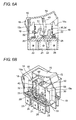
- a transmission member 63 including a stepping motor 60 and a cam member is assembled and accommodated in an inner space formed by assembling a cover 55 in a unit case 51.
- a pinion 62 that is of a small gear is attached to a turning shaft 61 of the stepping motor 60.
- the transmission member 63 including the cam member a pair of operating portions 66 and 67 laterally extends in parallel from an upper portion of a transmission member body 64, and a gear portion 68 is formed in a lower portion of the transmission member body 64.
- a spindle (not illustrated) projected in an upper stage of an inside surface of the unit case 51 is inserted in a shaft hole 65 of the transmission member 63 so as to be journaled in the shaft hole 65.
- the stepping motor 60 is assembled in a recess 52 (see Fig. 3 ) provided in a lower stage of the inside surface of the unit case 51.
- a retaining cylindrical shaft 56 projected from the inward surface of the cover 55 is fitted in a leading end of the spindle to prevent dropout of the transmission member 63.
- An elastic arm 57 of the cover 55 engages an engaging projection 53 of the unit case 51 to complete the remote control unit 50.
- the transmission member 63 can visually be recognized through an operating hole 54 of the remote control unit 50.
- shafts 71 and 71 are projected on the identical axis in outside surfaces opposed to each other, and an operation rod 72 (see Fig. 3 ) is integrally formed.
- the operation rod 72 extends downward from the central portion of a ceiling surface of the operation button 70, and can abut on the operating portions 66 and 67 of the transmission member 63.
- the pair of operation pieces 73 and 73 is integrally molded on both the sides of the operation rod 72.
- the operation pieces 73 abut on the bent portions 34 of the movable touch piece 30 to forcedly turn the movable touch piece 30, thereby enhancing the operating reliability.
- the fitting hole 74 (see Fig. 8 ) is made between the pair of operation pieces 73 and 73 in order to insert the upper end portion of the coil spring 40.
- the operation rod 72 is not necessarily integral with the operation button 70, but the operation rod 72 may separately be formed.
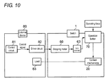
- a control circuit 81 of the external device 80 is connected to the stepping motor 60 of the switch 1 through a driver circuit 82.
- the contact mechanism 20 of the switch 1 is connected to a load 83 of the external device 80.
- the operation of the operation button 70 brings the movable contact 33 into contact with the fixed contact 28 to establish electric conduction to the load 83, and the operation of the operation button 70 also causes the opening edge portion of the operation button 70 to abut on the positioning step 19a of the box-shaped base 10 to regulate the position of the operation button 70.
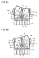
- the stepping motor 60 turns to turn the transmission member 63 as illustrated in Fig. 11 . Therefore, the operating portion 67 of the transmission member 63 presses the operation rod 72 of the operation button 70 to turn the operation button 70.
- the operation button 70 reaches a predetermined angle, the operation button 70 turns reversely by the spring force of the coil spring 40 to turn the movable touch piece 30. As a result, the movable contact 32 comes into contact with the fixed contact 25 to establish the electric conduction to the load 83.
- the stepping motor 60 is reversely rotated to turn the transmission member 63, and the operating portion 67 of the transmission member 63 separates from the operation rod 72 to return to the initial position. Therefore, the operation button 70 can manually be operated again. Then, the similar operation can be repeated in the reverse direction (see Fig. 12 ), and the switch 1 can continuously be operated by the remote control.
- the remote control unit 50 includes the stepping motor 60 and the transmission member 63, the stepping motor 60 includes the pinion 62, and the transmission member 63 constructed with the cam member includes the gear portion 68.
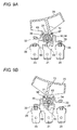
- the remote control unit 50 is not limited to the first embodiment.
- the remote control unit 50 may be constructed by a combination of the stepping motor 60 including the pinion 62 and the transmission member 63 including a rack 69.
- the transmission member 63 may directly be connected to the turning shaft 61 of the stepping motor 60.
- the third embodiment advantageously the number of components and assembling man-hours are reduced and a quick response characteristic can be obtained.
- the switch includes the two sets of contact mechanisms 20 and 20.
- the present invention may be applied to a switch having at least one contact mechanism.
- the switch is not limited to the case that the movable touch piece 30 includes the movable contacts on both the sides thereof.
- the movable touch piece 30 may include one movable contact on at least one side.
- the switch of the present invention is not limited to the embodiments, but the switch can be used in various applications.
Landscapes
- Push-Button Switches (AREA)
- Rotary Switch, Piano Key Switch, And Lever Switch (AREA)
- Mechanisms For Operating Contacts (AREA)
- Tumbler Switches (AREA)
- Switches With Compound Operations (AREA)
Applications Claiming Priority (1)
| Application Number | Priority Date | Filing Date | Title |
|---|---|---|---|
| JP2013108099A JP2014229475A (ja) | 2013-05-22 | 2013-05-22 | スイッチおよびその制御方法 |
Publications (1)
| Publication Number | Publication Date |
|---|---|
| EP2806442A1 true EP2806442A1 (de) | 2014-11-26 |
Family
ID=50513125
Family Applications (1)
| Application Number | Title | Priority Date | Filing Date |
|---|---|---|---|
| EP20140165480 Withdrawn EP2806442A1 (de) | 2013-05-22 | 2014-04-22 | Schalter und Steuerverfahren dafür |
Country Status (4)
| Country | Link |
|---|---|
| US (1) | US20140346026A1 (de) |
| EP (1) | EP2806442A1 (de) |
| JP (1) | JP2014229475A (de) |
| CN (2) | CN203983058U (de) |
Cited By (4)
| Publication number | Priority date | Publication date | Assignee | Title |
|---|---|---|---|---|
| CN104865850A (zh) * | 2015-03-19 | 2015-08-26 | 国网冀北电力有限公司唐山供电公司 | 一种万能转换开关的测控系统及方法 |
| DE102014109866A1 (de) * | 2014-07-14 | 2016-01-14 | Löwen Entertainment GmbH | Elektrischer Schalter und Unterhaltungsgerät |
| CN106373799A (zh) * | 2015-04-27 | 2017-02-01 | 苏州贝腾特电子科技有限公司 | 一种用于配电柜中的电力开关 |
| EP3720142B1 (de) * | 2017-11-28 | 2025-10-01 | Idec Corporation | Betriebsschaltereinheit, fernbedienungsendgerät und betriebssystem |
Families Citing this family (101)
| Publication number | Priority date | Publication date | Assignee | Title |
|---|---|---|---|---|
| JP2014229475A (ja) * | 2013-05-22 | 2014-12-08 | オムロン株式会社 | スイッチおよびその制御方法 |
| CN104851708A (zh) * | 2015-04-27 | 2015-08-19 | 苏州贝腾特电子科技有限公司 | 智能自动切换电力开关 |
| CN106298337A (zh) * | 2015-04-27 | 2017-01-04 | 苏州贝腾特电子科技有限公司 | 一种双电源自动切换电力开关 |
| CN104966628A (zh) * | 2015-04-27 | 2015-10-07 | 苏州君丰辰电子科技有限公司 | 用于配电开关中的易于安装的切换操作机构 |
| CN104867760A (zh) * | 2015-04-27 | 2015-08-26 | 苏州贝腾特电子科技有限公司 | 一种开关柜用智能电力开关的远程操作机构 |
| CN104851659A (zh) * | 2015-04-27 | 2015-08-19 | 苏州贝腾特电子科技有限公司 | 一种用于电力开关的智能远程操作机构 |
| CN104851712A (zh) * | 2015-04-27 | 2015-08-19 | 苏州君丰辰电子科技有限公司 | 用于输配电开关的切换操作机构 |
| CN104851649A (zh) * | 2015-04-27 | 2015-08-19 | 苏州君丰辰电子科技有限公司 | 一种用于输配电开关的切换操作机构 |
| CN104851675A (zh) * | 2015-04-27 | 2015-08-19 | 苏州君丰辰电子科技有限公司 | 一种手电动一体化切换操作机构 |
| CN104851686A (zh) * | 2015-04-27 | 2015-08-19 | 苏州君丰辰电子科技有限公司 | 用于配电开关中的切换操作机构 |
| CN104867719A (zh) * | 2015-04-27 | 2015-08-26 | 苏州君丰辰电子科技有限公司 | 双电源配电开关 |
| CN104867720A (zh) * | 2015-04-27 | 2015-08-26 | 苏州君丰辰电子科技有限公司 | 用于双电源转换开关中的切换操作机构 |
| CN104851671A (zh) * | 2015-04-27 | 2015-08-19 | 苏州君丰辰电子科技有限公司 | 双电源自动切换开关 |
| CN104867742A (zh) * | 2015-04-27 | 2015-08-26 | 苏州君丰辰电子科技有限公司 | 易于组装的配电开关 |
| CN104851639A (zh) * | 2015-04-27 | 2015-08-19 | 苏州君丰辰电子科技有限公司 | 一种新型输配电开关 |
| CN104867711A (zh) * | 2015-04-27 | 2015-08-26 | 苏州鱼得水电气科技有限公司 | 一种用于开关柜的电力开关 |
| CN104851623A (zh) * | 2015-04-27 | 2015-08-19 | 苏州君丰辰电子科技有限公司 | 用于电力开关的操作机构 |
| CN104867730A (zh) * | 2015-04-27 | 2015-08-26 | 苏州贝腾特电子科技有限公司 | 一种智能远程电动控制双电源电力开关 |
| CN104851676A (zh) * | 2015-04-27 | 2015-08-19 | 苏州君丰辰电子科技有限公司 | 一种新型智能家居电力开关 |
| CN104851684A (zh) * | 2015-04-27 | 2015-08-19 | 苏州君丰辰电子科技有限公司 | 用于智能家居电力开关的远程操作机构 |
| CN104851619A (zh) * | 2015-04-27 | 2015-08-19 | 苏州君丰辰电子科技有限公司 | 新型智能家居电力开关 |
| CN104851678A (zh) * | 2015-04-27 | 2015-08-19 | 苏州君丰辰电子科技有限公司 | 智能双电源转换开关 |
| CN104867746A (zh) * | 2015-04-27 | 2015-08-26 | 苏州君丰辰电子科技有限公司 | 一种智能双电源转换开关 |
| CN104851630A (zh) * | 2015-04-27 | 2015-08-19 | 苏州君丰辰电子科技有限公司 | 一种双电源电力开关 |
| CN104851692A (zh) * | 2015-04-27 | 2015-08-19 | 苏州君丰辰电子科技有限公司 | 一种双电源切换开关 |
| CN104867714A (zh) * | 2015-04-27 | 2015-08-26 | 苏州鱼得水电气科技有限公司 | 一种用于开关柜配电开关的手电动操作机构 |
| CN104851643A (zh) * | 2015-04-27 | 2015-08-19 | 苏州君丰辰电子科技有限公司 | 双电源切换开关 |
| CN104851681A (zh) * | 2015-04-27 | 2015-08-19 | 苏州君丰辰电子科技有限公司 | 智能家居双电源电力开关 |
| CN104851641A (zh) * | 2015-04-27 | 2015-08-19 | 苏州君丰辰电子科技有限公司 | 一种用于电力开关的电动操作机构 |
| CN106449230A (zh) * | 2015-04-27 | 2017-02-22 | 苏州贝腾特电子科技有限公司 | 一种智能自动切换电力开关 |
| CN104851624A (zh) * | 2015-04-27 | 2015-08-19 | 苏州君丰辰电子科技有限公司 | 一种用于智能家居双电源电力开关的远程操作机构 |
| CN106409560A (zh) * | 2015-04-27 | 2017-02-15 | 苏州贝腾特电子科技有限公司 | 一种用于配电柜中的远程控制开关 |
| CN104851668A (zh) * | 2015-04-27 | 2015-08-19 | 苏州君丰辰电子科技有限公司 | 双电源电力开关 |
| CN104851669A (zh) * | 2015-04-27 | 2015-08-19 | 苏州君丰辰电子科技有限公司 | 一种智能家居电力开关 |
| CN104867718A (zh) * | 2015-04-27 | 2015-08-26 | 苏州君丰辰电子科技有限公司 | 一种双电源自动切换开关 |
| CN104851648A (zh) * | 2015-04-27 | 2015-08-19 | 苏州君丰辰电子科技有限公司 | 输配电双电源开关 |
| CN104851645A (zh) * | 2015-04-27 | 2015-08-19 | 苏州君丰辰电子科技有限公司 | 用于智能家居双电源电力开关的远程操作机构 |
| CN104851690A (zh) * | 2015-04-27 | 2015-08-19 | 苏州君丰辰电子科技有限公司 | 一种用于配电开关中的切换操作机构 |
| CN106876183A (zh) * | 2015-04-27 | 2017-06-20 | 赵牧青 | 一种电力开关 |
| CN104851683A (zh) * | 2015-04-27 | 2015-08-19 | 苏州君丰辰电子科技有限公司 | 一种易于组装的智能家居电力开关 |
| CN104867724B (zh) * | 2015-04-27 | 2020-08-14 | 乐清市华尊电气有限公司 | 用于双电源开关中的切换操作机构 |
| CN104851628A (zh) * | 2015-04-27 | 2015-08-19 | 苏州君丰辰电子科技有限公司 | 一种用于智能家居电力开关的远程操作机构 |
| CN104867709A (zh) * | 2015-04-27 | 2015-08-26 | 苏州君丰辰电子科技有限公司 | 新型电力开关 |
| CN104867708A (zh) * | 2015-04-27 | 2015-08-26 | 苏州鱼得水电气科技有限公司 | 用于开关柜双电源配电开关的手电动操作机构 |
| CN104867754A (zh) * | 2015-04-27 | 2015-08-26 | 苏州贝腾特电子科技有限公司 | 智能远程操控双电源电力开关 |
| CN104867715A (zh) * | 2015-04-27 | 2015-08-26 | 苏州鱼得水电气科技有限公司 | 一种用于高低压开关柜的配电开关 |
| CN104851700A (zh) * | 2015-04-27 | 2015-08-19 | 苏州君丰辰电子科技有限公司 | 一种新型电力开关 |
| CN104851640A (zh) * | 2015-04-27 | 2015-08-19 | 苏州君丰辰电子科技有限公司 | 双电源转换开关 |
| CN104851717A (zh) * | 2015-04-27 | 2015-08-19 | 苏州鱼得水电气科技有限公司 | 一种用于开关柜的双电源电力开关 |
| CN104867743A (zh) * | 2015-04-27 | 2015-08-26 | 苏州贝腾特电子科技有限公司 | 一种智能远程电动控制电力开关 |
| CN104867731A (zh) * | 2015-04-27 | 2015-08-26 | 苏州鱼得水电气科技有限公司 | 用于高低压开关柜的双电源配电开关 |
| CN106876184A (zh) * | 2015-04-27 | 2017-06-20 | 赵牧青 | 具有切换操作机构的输配电开关 |
| CN104867733A (zh) * | 2015-04-27 | 2015-08-26 | 苏州贝腾特电子科技有限公司 | 开关柜用智能电力开关的远程操作机构 |
| CN104851679A (zh) * | 2015-04-27 | 2015-08-19 | 苏州君丰辰电子科技有限公司 | 新型配电开关 |
| CN104867752A (zh) * | 2015-04-27 | 2015-08-26 | 苏州君丰辰电子科技有限公司 | 新型手电动一体化切换操作机构 |
| CN104867710A (zh) * | 2015-04-27 | 2015-08-26 | 苏州鱼得水电气科技有限公司 | 用于电力开关柜的配电开关 |
| CN104851688A (zh) * | 2015-04-27 | 2015-08-19 | 苏州君丰辰电子科技有限公司 | 用于双电源转换开关的手电动一体化切换操作机构 |
| CN104851642A (zh) * | 2015-04-27 | 2015-08-19 | 苏州君丰辰电子科技有限公司 | 改进型配电开关 |
| CN104851661A (zh) * | 2015-04-27 | 2015-08-19 | 苏州鱼得水电气科技有限公司 | 用于电力开关柜的双电源配电开关 |
| CN104867747A (zh) * | 2015-04-27 | 2015-08-26 | 苏州君丰辰电子科技有限公司 | 一种输配电双电源开关 |
| CN104867748A (zh) * | 2015-04-27 | 2015-08-26 | 苏州君丰辰电子科技有限公司 | 易于组装的智能家居电力开关 |
| CN104851636A (zh) * | 2015-04-27 | 2015-08-19 | 苏州君丰辰电子科技有限公司 | 双电源自动转换开关 |
| CN104867738A (zh) * | 2015-04-27 | 2015-08-26 | 苏州贝腾特电子科技有限公司 | 用于开关柜的远程智能双电源开关 |
| CN104867736A (zh) * | 2015-04-27 | 2015-08-26 | 苏州贝腾特电子科技有限公司 | 一种用于开关柜的远程智能双电源开关 |
| CN104867721A (zh) * | 2015-04-27 | 2015-08-26 | 苏州君丰辰电子科技有限公司 | 一种用于输配电双电源开关的切换操作机构 |
| CN104851695A (zh) * | 2015-04-27 | 2015-08-19 | 苏州君丰辰电子科技有限公司 | 双电源转换开关 |
| CN104851637A (zh) * | 2015-04-27 | 2015-08-19 | 苏州君丰辰电子科技有限公司 | 新型输配电开关 |
| CN104851674A (zh) * | 2015-04-27 | 2015-08-19 | 苏州贝腾特电子科技有限公司 | 一种用于开关柜的远程控制电力开关 |
| CN104851687A (zh) * | 2015-04-27 | 2015-08-19 | 苏州君丰辰电子科技有限公司 | 一种配电开关 |
| CN104835660A (zh) * | 2015-04-27 | 2015-08-12 | 胡小青 | 智能家居墙壁电力开关 |
| CN104851672A (zh) * | 2015-04-27 | 2015-08-19 | 苏州君丰辰电子科技有限公司 | 一种输配电开关 |
| CN104867722A (zh) * | 2015-04-27 | 2015-08-26 | 苏州君丰辰电子科技有限公司 | 用于双电源配电开关中的切换操作机构 |
| CN104851673A (zh) * | 2015-04-27 | 2015-08-19 | 苏州君丰辰电子科技有限公司 | 一种用于电力开关的操作机构 |
| CN104851621A (zh) * | 2015-04-27 | 2015-08-19 | 苏州君丰辰电子科技有限公司 | 用于电力开关的电动操作机构 |
| CN104851704A (zh) * | 2015-04-27 | 2015-08-19 | 苏州君丰辰电子科技有限公司 | 用于输配电双电源开关的切换操作机构 |
| CN104934240A (zh) * | 2015-04-27 | 2015-09-23 | 苏州君丰辰电子科技有限公司 | 一种用于双电源转换开关中的切换操作机构 |
| CN104867765A (zh) * | 2015-04-27 | 2015-08-26 | 苏州鱼得水电气科技有限公司 | 用于开关柜的电力开关 |
| CN104851710A (zh) * | 2015-04-27 | 2015-08-19 | 苏州君丰辰电子科技有限公司 | 一种双电源开关 |
| CN104851680A (zh) * | 2015-04-27 | 2015-08-19 | 苏州君丰辰电子科技有限公司 | 一种易于组装的配电开关 |
| CN104851638A (zh) * | 2015-04-27 | 2015-08-19 | 苏州君丰辰电子科技有限公司 | 一种新型配电开关 |
| CN104867761A (zh) * | 2015-04-27 | 2015-08-26 | 苏州鱼得水电气科技有限公司 | 一种用于高低压开关柜的双电源配电开关 |
| CN104867766A (zh) * | 2015-04-27 | 2015-08-26 | 苏州贝腾特电子科技有限公司 | 一种用于智能双电源电力开关的远程电动操作机构 |
| CN104867723A (zh) * | 2015-04-27 | 2015-08-26 | 苏州君丰辰电子科技有限公司 | 智能家居电力开关 |
| CN104867757A (zh) * | 2015-04-27 | 2015-08-26 | 苏州君丰辰电子科技有限公司 | 双电源开关 |
| CN104851633A (zh) * | 2015-04-27 | 2015-08-19 | 苏州君丰辰电子科技有限公司 | 易于组装的双电源电力开关 |
| CN104851646A (zh) * | 2015-04-27 | 2015-08-19 | 苏州君丰辰电子科技有限公司 | 一种新型手电动一体化切换操作机构 |
| CN104867707A (zh) * | 2015-04-27 | 2015-08-26 | 苏州鱼得水电气科技有限公司 | 用于配电柜的双电源电力开关 |
| CN104867749A (zh) * | 2015-04-27 | 2015-08-26 | 苏州贝腾特电子科技有限公司 | 用于配电柜中的智能控制开关 |
| CN104851647A (zh) * | 2015-04-27 | 2015-08-19 | 苏州君丰辰电子科技有限公司 | 一种双电源配电开关 |
| CN104851644A (zh) * | 2015-04-27 | 2015-08-19 | 苏州君丰辰电子科技有限公司 | 电力双电源开关 |
| CN104867756A (zh) * | 2015-04-27 | 2015-08-26 | 苏州君丰辰电子科技有限公司 | 电力开关 |
| CN104851706A (zh) * | 2015-04-27 | 2015-08-19 | 苏州君丰辰电子科技有限公司 | 易于组装的输配电开关 |
| CN104851632A (zh) * | 2015-04-27 | 2015-08-19 | 苏州君丰辰电子科技有限公司 | 一种双电源转换开关 |
| CN104851682A (zh) * | 2015-04-27 | 2015-08-19 | 苏州君丰辰电子科技有限公司 | 一种双电源切换开关 |
| CN104934248A (zh) * | 2015-04-27 | 2015-09-23 | 苏州君丰辰电子科技有限公司 | 一种用于双电源配电开关中的切换操作机构 |
| CN104867745A (zh) * | 2015-04-27 | 2015-08-26 | 苏州贝腾特电子科技有限公司 | 智能双电源自动切换电力开关 |
| WO2017170520A1 (ja) * | 2016-03-30 | 2017-10-05 | パナソニックIpマネジメント株式会社 | コントロール器 |
| JP6406376B2 (ja) * | 2017-03-13 | 2018-10-17 | オムロン株式会社 | スイッチ |
| TWI631589B (zh) * | 2017-12-11 | 2018-08-01 | 普易科技股份有限公司 | 開關結構 |
| CN114121538B (zh) * | 2020-08-31 | 2023-10-27 | 深圳市万普拉斯科技有限公司 | 一种输入结构及电子设备 |
| KR102214410B1 (ko) * | 2020-12-04 | 2021-02-08 | 방재용 | 차량 기어 노브 |
Citations (4)
| Publication number | Priority date | Publication date | Assignee | Title |
|---|---|---|---|---|
| DE10040713A1 (de) * | 1999-08-21 | 2001-03-29 | Marquardt Gmbh | Elektrischer Schalter |
| JP2003331674A (ja) | 2002-05-14 | 2003-11-21 | Konica Minolta Holdings Inc | スイッチ及び画像形成装置 |
| US6714106B1 (en) * | 2002-01-04 | 2004-03-30 | Reliance Controls Corporation | Switch having integral remote actuating device |
| EP2442327A1 (de) * | 2010-10-14 | 2012-04-18 | Omron Corporation | Schalter und Herstellungsverfahren dafür |
Family Cites Families (48)
| Publication number | Priority date | Publication date | Assignee | Title |
|---|---|---|---|---|
| US3225153A (en) * | 1963-06-28 | 1965-12-21 | Carling Electric Inc | Interlocking mechanism for a dual rocker-button actuated electric multi-switch |
| GB1332657A (en) * | 1970-07-29 | 1973-10-03 | Turnock Ltd George | Rock switches |
| US3632914A (en) * | 1970-12-28 | 1972-01-04 | Mc Gill Mfg Co | Key-operated electrical switch |
| US3678229A (en) * | 1971-10-13 | 1972-07-18 | Mc Gill Mfg Co | Spring mounted key for electrical switch |
| US3906176A (en) * | 1974-08-02 | 1975-09-16 | Hubbell Inc Harvey | Tamperproof switch |
| US3906369A (en) * | 1974-09-18 | 1975-09-16 | R O Products Inc | Function switch arrangement for hand-held remote control unit |
| US4221941A (en) * | 1979-01-08 | 1980-09-09 | Gte Sylvania Wiring Devices Incorporated | Rocker switch having improved contact-operating means |
| US4230917A (en) * | 1979-02-12 | 1980-10-28 | Mcgill Manufacturing Company, Inc. | Removable-key rocker type switch for two circuits |
| JPS618522Y2 (de) * | 1979-06-01 | 1986-03-17 | ||
| JPS603817A (ja) * | 1983-06-20 | 1985-01-10 | 株式会社東海理化電機製作所 | モ−タ制御用スイツチ装置 |
| JPS61189523U (de) * | 1985-05-17 | 1986-11-26 | ||
| JPH0637557Y2 (ja) * | 1987-01-19 | 1994-09-28 | アルプス電気株式会社 | スイツチ装置 |
| JPS63194443U (de) * | 1987-06-01 | 1988-12-14 | ||
| JPS63194442U (de) * | 1987-06-01 | 1988-12-14 | ||
| US5051550A (en) * | 1989-03-31 | 1991-09-24 | Kransco | Control mechanism for an on-off switch |
| JPH02136940U (de) * | 1989-04-19 | 1990-11-15 | ||
| JPH037241U (de) * | 1989-06-12 | 1991-01-24 | ||
| US5045654A (en) * | 1989-12-14 | 1991-09-03 | Eaton Corporation | Switch assembly |
| US5053592A (en) * | 1990-02-28 | 1991-10-01 | Eaton Corporation | Low current switching apparatus having detent structure providing tactile feedback |
| US5130506A (en) * | 1990-02-28 | 1992-07-14 | Eaton Corporation | Low current switching apparatus having detent structure providing tactile feedback |
| JP2573191Y2 (ja) * | 1991-02-22 | 1998-05-28 | アルプス電気株式会社 | 揺動スイツチの可動接片支持構造 |
| US5262678A (en) * | 1991-06-21 | 1993-11-16 | Lutron Electronics Co., Inc. | Wallbox-mountable switch and dimmer |
| JP2525658Y2 (ja) * | 1991-09-18 | 1997-02-12 | アルプス電気株式会社 | シーソ型スイッチ |
| US6005308A (en) * | 1993-03-31 | 1999-12-21 | Lutron Electronics Co., Inc. | Electrical switch and dimmer control device |
| JPH0719932U (ja) * | 1993-09-20 | 1995-04-07 | 株式会社東海理化電機製作所 | スイッチ装置 |
| US5833048A (en) * | 1995-02-07 | 1998-11-10 | Eaton Corporation | Rocker switch especially for vehicles |
| US5598918A (en) * | 1995-05-18 | 1997-02-04 | Trw Inc. | Switch for vehicle power window |
| US5638948A (en) * | 1995-06-05 | 1997-06-17 | Onan Corporation | Electric transfer switch having three-position toggle mechanism |
| US5662213A (en) * | 1996-03-04 | 1997-09-02 | Delta Systems, Inc. | Trim switch with waterproof boot |
| JP3723627B2 (ja) * | 1996-04-04 | 2005-12-07 | アルプス電気株式会社 | スイッチ装置の製造方法 |
| US6388221B1 (en) * | 1996-05-11 | 2002-05-14 | Delphi Technologies, Inc. | Window winder switch |
| US5719361A (en) * | 1996-08-09 | 1998-02-17 | Packard Hughes Interconnect Company | Mechanism for multiple dome dual detent |
| US5803243A (en) * | 1997-07-25 | 1998-09-08 | General Motors Corporation | Latching rocker switch |
| US5902972A (en) * | 1997-09-22 | 1999-05-11 | General Motors Corporation | Three function rocker/push switch |
| US5990431A (en) * | 1998-05-18 | 1999-11-23 | Marquardt Switches, Inc. | Protective cover for rocker switch |
| JP3870748B2 (ja) * | 2001-10-29 | 2007-01-24 | 松下電器産業株式会社 | レバースイッチ |
| US6734381B2 (en) * | 2001-11-13 | 2004-05-11 | Lutron Electronics Co., Inc. | Wallbox dimmer switch having side-by-side pushbutton and dimmer actuators |
| JP3964754B2 (ja) * | 2002-07-30 | 2007-08-22 | アルプス電気株式会社 | スイッチ装置 |
| US7028989B2 (en) * | 2002-11-27 | 2006-04-18 | Dura Global Technologies, Inc. | Tire carrier |
| ES2238671T3 (es) * | 2003-02-28 | 2005-09-01 | Signal Lux Mds S.R.L. | Interruptor de seguridad. |
| US7105763B2 (en) * | 2003-10-14 | 2006-09-12 | Lutron Electronics Co., Inc. | Switch assembly |
| US7400239B2 (en) * | 2004-09-03 | 2008-07-15 | Simply Automated, Incorporated | Universal control apparatus and methods |
| US8003904B2 (en) * | 2006-02-22 | 2011-08-23 | Leviton Manufacturing Co., Inc. | Dimmer switch |
| US7745750B2 (en) * | 2006-03-17 | 2010-06-29 | Lutron Electronics Co., Inc. | Dimmer switch having an illuminated button and slider slot |
| US8643220B1 (en) * | 2010-03-24 | 2014-02-04 | Pass & Seymour, Inc. | Toggle switch and variable actuator control |
| JP4905581B2 (ja) * | 2010-07-28 | 2012-03-28 | オムロン株式会社 | スイッチ及び電子機器 |
| JP4905582B2 (ja) * | 2010-08-25 | 2012-03-28 | オムロン株式会社 | スイッチ及び電子機器 |
| JP2014229475A (ja) * | 2013-05-22 | 2014-12-08 | オムロン株式会社 | スイッチおよびその制御方法 |
-
2013
- 2013-05-22 JP JP2013108099A patent/JP2014229475A/ja active Pending
-
2014
- 2014-04-07 US US14/246,813 patent/US20140346026A1/en not_active Abandoned
- 2014-04-09 CN CN201420170115.0U patent/CN203983058U/zh not_active Expired - Lifetime
- 2014-04-09 CN CN201410140877.0A patent/CN104183394A/zh active Pending
- 2014-04-22 EP EP20140165480 patent/EP2806442A1/de not_active Withdrawn
Patent Citations (4)
| Publication number | Priority date | Publication date | Assignee | Title |
|---|---|---|---|---|
| DE10040713A1 (de) * | 1999-08-21 | 2001-03-29 | Marquardt Gmbh | Elektrischer Schalter |
| US6714106B1 (en) * | 2002-01-04 | 2004-03-30 | Reliance Controls Corporation | Switch having integral remote actuating device |
| JP2003331674A (ja) | 2002-05-14 | 2003-11-21 | Konica Minolta Holdings Inc | スイッチ及び画像形成装置 |
| EP2442327A1 (de) * | 2010-10-14 | 2012-04-18 | Omron Corporation | Schalter und Herstellungsverfahren dafür |
Cited By (5)
| Publication number | Priority date | Publication date | Assignee | Title |
|---|---|---|---|---|
| DE102014109866A1 (de) * | 2014-07-14 | 2016-01-14 | Löwen Entertainment GmbH | Elektrischer Schalter und Unterhaltungsgerät |
| DE102014109866B4 (de) | 2014-07-14 | 2021-11-25 | Löwen Entertainment GmbH | Elektrischer Schalter und Unterhaltungsgerät |
| CN104865850A (zh) * | 2015-03-19 | 2015-08-26 | 国网冀北电力有限公司唐山供电公司 | 一种万能转换开关的测控系统及方法 |
| CN106373799A (zh) * | 2015-04-27 | 2017-02-01 | 苏州贝腾特电子科技有限公司 | 一种用于配电柜中的电力开关 |
| EP3720142B1 (de) * | 2017-11-28 | 2025-10-01 | Idec Corporation | Betriebsschaltereinheit, fernbedienungsendgerät und betriebssystem |
Also Published As
| Publication number | Publication date |
|---|---|
| JP2014229475A (ja) | 2014-12-08 |
| CN104183394A (zh) | 2014-12-03 |
| US20140346026A1 (en) | 2014-11-27 |
| CN203983058U (zh) | 2014-12-03 |
Similar Documents
| Publication | Publication Date | Title |
|---|---|---|
| EP2806442A1 (de) | Schalter und Steuerverfahren dafür | |
| US9324523B2 (en) | Power generation device | |
| JP6910014B2 (ja) | 接点装置および当該接点装置を搭載した電磁継電器 | |
| JP6025414B2 (ja) | 電磁継電器 | |
| EP2768004B1 (de) | Elektromagnetisches Relais | |
| EP3264437A2 (de) | Elektromagnetisches relais | |
| JP5239420B2 (ja) | 電磁継電器の磁石保持構造 | |
| JP4798115B2 (ja) | 電磁継電器 | |
| EP2945175A1 (de) | Kontaktvorrichtung | |
| US10995849B2 (en) | Operation device and vehicular shifting apparatus using operation device | |
| EP3550397B1 (de) | Betätigungsvorrichtung und fahrzeugschaltvorrichtung mit betätigungsvorrichtung | |
| JP4952840B1 (ja) | 電磁継電器 | |
| JP6119286B2 (ja) | 電磁継電器 | |
| JP6319684B2 (ja) | 電磁継電器 | |
| JP5591132B2 (ja) | 永久磁石作動型スイッチ | |
| EP2706551B1 (de) | Elektrische Magnetvorrichtung und Schalter damit | |
| KR20160050733A (ko) | 릴레이 장치 | |
| JP2010062042A (ja) | リレー | |
| JP6837562B2 (ja) | テストボタン付きの電気機械リレー | |
| JP5541819B2 (ja) | リレー | |
| JP2017147197A (ja) | 電磁継電器 | |
| JPH1116471A (ja) | リレー | |
| JP2001155614A (ja) | リモコンリレー | |
| JP2009152008A (ja) | スイッチ装置 | |
| JP2011228318A (ja) | 電磁ソレノイド |
Legal Events
| Date | Code | Title | Description |
|---|---|---|---|
| PUAI | Public reference made under article 153(3) epc to a published international application that has entered the european phase |
Free format text: ORIGINAL CODE: 0009012 |
|
| 17P | Request for examination filed |
Effective date: 20140422 |
|
| AK | Designated contracting states |
Kind code of ref document: A1 Designated state(s): AL AT BE BG CH CY CZ DE DK EE ES FI FR GB GR HR HU IE IS IT LI LT LU LV MC MK MT NL NO PL PT RO RS SE SI SK SM TR |
|
| AX | Request for extension of the european patent |
Extension state: BA ME |
|
| R17P | Request for examination filed (corrected) |
Effective date: 20150323 |
|
| RBV | Designated contracting states (corrected) |
Designated state(s): AL AT BE BG CH CY CZ DE DK EE ES FI FR GB GR HR HU IE IS IT LI LT LU LV MC MK MT NL NO PL PT RO RS SE SI SK SM TR |
|
| 17Q | First examination report despatched |
Effective date: 20160603 |
|
| STAA | Information on the status of an ep patent application or granted ep patent |
Free format text: STATUS: EXAMINATION IS IN PROGRESS |
|
| STAA | Information on the status of an ep patent application or granted ep patent |
Free format text: STATUS: THE APPLICATION IS DEEMED TO BE WITHDRAWN |
|
| 18D | Application deemed to be withdrawn |
Effective date: 20161014 |