EP2800677B1 - Standardlichtquelle laser-diode - Google Patents
Standardlichtquelle laser-diode Download PDFInfo
- Publication number
- EP2800677B1 EP2800677B1 EP13716169.1A EP13716169A EP2800677B1 EP 2800677 B1 EP2800677 B1 EP 2800677B1 EP 13716169 A EP13716169 A EP 13716169A EP 2800677 B1 EP2800677 B1 EP 2800677B1
- Authority
- EP
- European Patent Office
- Prior art keywords
- light source
- source module
- laser light
- vehicle headlamp
- laser
- Prior art date
- Legal status (The legal status is an assumption and is not a legal conclusion. Google has not performed a legal analysis and makes no representation as to the accuracy of the status listed.)
- Active
Links
Images

Classifications
-
- F—MECHANICAL ENGINEERING; LIGHTING; HEATING; WEAPONS; BLASTING
- F21—LIGHTING
- F21S—NON-PORTABLE LIGHTING DEVICES; SYSTEMS THEREOF; VEHICLE LIGHTING DEVICES SPECIALLY ADAPTED FOR VEHICLE EXTERIORS
- F21S41/00—Illuminating devices specially adapted for vehicle exteriors, e.g. headlamps
- F21S41/10—Illuminating devices specially adapted for vehicle exteriors, e.g. headlamps characterised by the light source
- F21S41/12—Illuminating devices specially adapted for vehicle exteriors, e.g. headlamps characterised by the light source characterised by the type of emitted light
- F21S41/13—Ultraviolet light; Infrared light
-
- F—MECHANICAL ENGINEERING; LIGHTING; HEATING; WEAPONS; BLASTING
- F21—LIGHTING
- F21S—NON-PORTABLE LIGHTING DEVICES; SYSTEMS THEREOF; VEHICLE LIGHTING DEVICES SPECIALLY ADAPTED FOR VEHICLE EXTERIORS
- F21S41/00—Illuminating devices specially adapted for vehicle exteriors, e.g. headlamps
- F21S41/10—Illuminating devices specially adapted for vehicle exteriors, e.g. headlamps characterised by the light source
- F21S41/14—Illuminating devices specially adapted for vehicle exteriors, e.g. headlamps characterised by the light source characterised by the type of light source
- F21S41/16—Laser light sources
-
- B—PERFORMING OPERATIONS; TRANSPORTING
- B60—VEHICLES IN GENERAL
- B60Q—ARRANGEMENT OF SIGNALLING OR LIGHTING DEVICES, THE MOUNTING OR SUPPORTING THEREOF OR CIRCUITS THEREFOR, FOR VEHICLES IN GENERAL
- B60Q1/00—Arrangement of optical signalling or lighting devices, the mounting or supporting thereof or circuits therefor
- B60Q1/0017—Devices integrating an element dedicated to another function
- B60Q1/0023—Devices integrating an element dedicated to another function the element being a sensor, e.g. distance sensor, camera
-
- B—PERFORMING OPERATIONS; TRANSPORTING
- B60—VEHICLES IN GENERAL
- B60Q—ARRANGEMENT OF SIGNALLING OR LIGHTING DEVICES, THE MOUNTING OR SUPPORTING THEREOF OR CIRCUITS THEREFOR, FOR VEHICLES IN GENERAL
- B60Q1/00—Arrangement of optical signalling or lighting devices, the mounting or supporting thereof or circuits therefor
- B60Q1/02—Arrangement of optical signalling or lighting devices, the mounting or supporting thereof or circuits therefor the devices being primarily intended to illuminate the way ahead or to illuminate other areas of way or environments
- B60Q1/04—Arrangement of optical signalling or lighting devices, the mounting or supporting thereof or circuits therefor the devices being primarily intended to illuminate the way ahead or to illuminate other areas of way or environments the devices being headlights
- B60Q1/06—Arrangement of optical signalling or lighting devices, the mounting or supporting thereof or circuits therefor the devices being primarily intended to illuminate the way ahead or to illuminate other areas of way or environments the devices being headlights adjustable, e.g. remotely-controlled from inside vehicle
- B60Q1/08—Arrangement of optical signalling or lighting devices, the mounting or supporting thereof or circuits therefor the devices being primarily intended to illuminate the way ahead or to illuminate other areas of way or environments the devices being headlights adjustable, e.g. remotely-controlled from inside vehicle automatically
- B60Q1/10—Arrangement of optical signalling or lighting devices, the mounting or supporting thereof or circuits therefor the devices being primarily intended to illuminate the way ahead or to illuminate other areas of way or environments the devices being headlights adjustable, e.g. remotely-controlled from inside vehicle automatically due to vehicle inclination, e.g. due to load distribution
-
- B—PERFORMING OPERATIONS; TRANSPORTING
- B60—VEHICLES IN GENERAL
- B60Q—ARRANGEMENT OF SIGNALLING OR LIGHTING DEVICES, THE MOUNTING OR SUPPORTING THEREOF OR CIRCUITS THEREFOR, FOR VEHICLES IN GENERAL
- B60Q11/00—Arrangement of monitoring devices for devices provided for in groups B60Q1/00 - B60Q9/00
-
- F—MECHANICAL ENGINEERING; LIGHTING; HEATING; WEAPONS; BLASTING
- F21—LIGHTING
- F21K—NON-ELECTRIC LIGHT SOURCES USING LUMINESCENCE; LIGHT SOURCES USING ELECTROCHEMILUMINESCENCE; LIGHT SOURCES USING CHARGES OF COMBUSTIBLE MATERIAL; LIGHT SOURCES USING SEMICONDUCTOR DEVICES AS LIGHT-GENERATING ELEMENTS; LIGHT SOURCES NOT OTHERWISE PROVIDED FOR
- F21K9/00—Light sources using semiconductor devices as light-generating elements, e.g. using light-emitting diodes [LED] or lasers
- F21K9/60—Optical arrangements integrated in the light source, e.g. for improving the colour rendering index or the light extraction
- F21K9/61—Optical arrangements integrated in the light source, e.g. for improving the colour rendering index or the light extraction using light guides
-
- F—MECHANICAL ENGINEERING; LIGHTING; HEATING; WEAPONS; BLASTING
- F21—LIGHTING
- F21K—NON-ELECTRIC LIGHT SOURCES USING LUMINESCENCE; LIGHT SOURCES USING ELECTROCHEMILUMINESCENCE; LIGHT SOURCES USING CHARGES OF COMBUSTIBLE MATERIAL; LIGHT SOURCES USING SEMICONDUCTOR DEVICES AS LIGHT-GENERATING ELEMENTS; LIGHT SOURCES NOT OTHERWISE PROVIDED FOR
- F21K9/00—Light sources using semiconductor devices as light-generating elements, e.g. using light-emitting diodes [LED] or lasers
- F21K9/60—Optical arrangements integrated in the light source, e.g. for improving the colour rendering index or the light extraction
- F21K9/64—Optical arrangements integrated in the light source, e.g. for improving the colour rendering index or the light extraction using wavelength conversion means distinct or spaced from the light-generating element, e.g. a remote phosphor layer
-
- F—MECHANICAL ENGINEERING; LIGHTING; HEATING; WEAPONS; BLASTING
- F21—LIGHTING
- F21S—NON-PORTABLE LIGHTING DEVICES; SYSTEMS THEREOF; VEHICLE LIGHTING DEVICES SPECIALLY ADAPTED FOR VEHICLE EXTERIORS
- F21S41/00—Illuminating devices specially adapted for vehicle exteriors, e.g. headlamps
- F21S41/10—Illuminating devices specially adapted for vehicle exteriors, e.g. headlamps characterised by the light source
- F21S41/14—Illuminating devices specially adapted for vehicle exteriors, e.g. headlamps characterised by the light source characterised by the type of light source
- F21S41/141—Light emitting diodes [LED]
- F21S41/147—Light emitting diodes [LED] the main emission direction of the LED being angled to the optical axis of the illuminating device
-
- F—MECHANICAL ENGINEERING; LIGHTING; HEATING; WEAPONS; BLASTING
- F21—LIGHTING
- F21S—NON-PORTABLE LIGHTING DEVICES; SYSTEMS THEREOF; VEHICLE LIGHTING DEVICES SPECIALLY ADAPTED FOR VEHICLE EXTERIORS
- F21S41/00—Illuminating devices specially adapted for vehicle exteriors, e.g. headlamps
- F21S41/10—Illuminating devices specially adapted for vehicle exteriors, e.g. headlamps characterised by the light source
- F21S41/14—Illuminating devices specially adapted for vehicle exteriors, e.g. headlamps characterised by the light source characterised by the type of light source
- F21S41/176—Light sources where the light is generated by photoluminescent material spaced from a primary light generating element
-
- F—MECHANICAL ENGINEERING; LIGHTING; HEATING; WEAPONS; BLASTING
- F21—LIGHTING
- F21S—NON-PORTABLE LIGHTING DEVICES; SYSTEMS THEREOF; VEHICLE LIGHTING DEVICES SPECIALLY ADAPTED FOR VEHICLE EXTERIORS
- F21S41/00—Illuminating devices specially adapted for vehicle exteriors, e.g. headlamps
- F21S41/10—Illuminating devices specially adapted for vehicle exteriors, e.g. headlamps characterised by the light source
- F21S41/19—Attachment of light sources or lamp holders
- F21S41/192—Details of lamp holders, terminals or connectors
-
- F—MECHANICAL ENGINEERING; LIGHTING; HEATING; WEAPONS; BLASTING
- F21—LIGHTING
- F21S—NON-PORTABLE LIGHTING DEVICES; SYSTEMS THEREOF; VEHICLE LIGHTING DEVICES SPECIALLY ADAPTED FOR VEHICLE EXTERIORS
- F21S41/00—Illuminating devices specially adapted for vehicle exteriors, e.g. headlamps
- F21S41/20—Illuminating devices specially adapted for vehicle exteriors, e.g. headlamps characterised by refractors, transparent cover plates, light guides or filters
- F21S41/24—Light guides
-
- F—MECHANICAL ENGINEERING; LIGHTING; HEATING; WEAPONS; BLASTING
- F21—LIGHTING
- F21S—NON-PORTABLE LIGHTING DEVICES; SYSTEMS THEREOF; VEHICLE LIGHTING DEVICES SPECIALLY ADAPTED FOR VEHICLE EXTERIORS
- F21S41/00—Illuminating devices specially adapted for vehicle exteriors, e.g. headlamps
- F21S41/20—Illuminating devices specially adapted for vehicle exteriors, e.g. headlamps characterised by refractors, transparent cover plates, light guides or filters
- F21S41/285—Refractors, transparent cover plates, light guides or filters not provided in groups F21S41/24 - F21S41/2805
-
- F—MECHANICAL ENGINEERING; LIGHTING; HEATING; WEAPONS; BLASTING
- F21—LIGHTING
- F21S—NON-PORTABLE LIGHTING DEVICES; SYSTEMS THEREOF; VEHICLE LIGHTING DEVICES SPECIALLY ADAPTED FOR VEHICLE EXTERIORS
- F21S41/00—Illuminating devices specially adapted for vehicle exteriors, e.g. headlamps
- F21S41/30—Illuminating devices specially adapted for vehicle exteriors, e.g. headlamps characterised by reflectors
- F21S41/32—Optical layout thereof
- F21S41/321—Optical layout thereof the reflector being a surface of revolution or a planar surface, e.g. truncated
-
- F—MECHANICAL ENGINEERING; LIGHTING; HEATING; WEAPONS; BLASTING
- F21—LIGHTING
- F21S—NON-PORTABLE LIGHTING DEVICES; SYSTEMS THEREOF; VEHICLE LIGHTING DEVICES SPECIALLY ADAPTED FOR VEHICLE EXTERIORS
- F21S41/00—Illuminating devices specially adapted for vehicle exteriors, e.g. headlamps
- F21S41/30—Illuminating devices specially adapted for vehicle exteriors, e.g. headlamps characterised by reflectors
- F21S41/32—Optical layout thereof
- F21S41/36—Combinations of two or more separate reflectors
- F21S41/365—Combinations of two or more separate reflectors successively reflecting the light
-
- F—MECHANICAL ENGINEERING; LIGHTING; HEATING; WEAPONS; BLASTING
- F21—LIGHTING
- F21S—NON-PORTABLE LIGHTING DEVICES; SYSTEMS THEREOF; VEHICLE LIGHTING DEVICES SPECIALLY ADAPTED FOR VEHICLE EXTERIORS
- F21S41/00—Illuminating devices specially adapted for vehicle exteriors, e.g. headlamps
- F21S41/30—Illuminating devices specially adapted for vehicle exteriors, e.g. headlamps characterised by reflectors
- F21S41/39—Attachment thereof
-
- F—MECHANICAL ENGINEERING; LIGHTING; HEATING; WEAPONS; BLASTING
- F21—LIGHTING
- F21S—NON-PORTABLE LIGHTING DEVICES; SYSTEMS THEREOF; VEHICLE LIGHTING DEVICES SPECIALLY ADAPTED FOR VEHICLE EXTERIORS
- F21S43/00—Signalling devices specially adapted for vehicle exteriors, e.g. brake lamps, direction indicator lights or reversing lights
-
- F—MECHANICAL ENGINEERING; LIGHTING; HEATING; WEAPONS; BLASTING
- F21—LIGHTING
- F21S—NON-PORTABLE LIGHTING DEVICES; SYSTEMS THEREOF; VEHICLE LIGHTING DEVICES SPECIALLY ADAPTED FOR VEHICLE EXTERIORS
- F21S45/00—Arrangements within vehicle lighting devices specially adapted for vehicle exteriors, for purposes other than emission or distribution of light
- F21S45/10—Protection of lighting devices
-
- F—MECHANICAL ENGINEERING; LIGHTING; HEATING; WEAPONS; BLASTING
- F21—LIGHTING
- F21S—NON-PORTABLE LIGHTING DEVICES; SYSTEMS THEREOF; VEHICLE LIGHTING DEVICES SPECIALLY ADAPTED FOR VEHICLE EXTERIORS
- F21S45/00—Arrangements within vehicle lighting devices specially adapted for vehicle exteriors, for purposes other than emission or distribution of light
- F21S45/40—Cooling of lighting devices
- F21S45/47—Passive cooling, e.g. using fins, thermal conductive elements or openings
- F21S45/48—Passive cooling, e.g. using fins, thermal conductive elements or openings with means for conducting heat from the inside to the outside of the lighting devices, e.g. with fins on the outer surface of the lighting device
-
- F—MECHANICAL ENGINEERING; LIGHTING; HEATING; WEAPONS; BLASTING
- F21—LIGHTING
- F21S—NON-PORTABLE LIGHTING DEVICES; SYSTEMS THEREOF; VEHICLE LIGHTING DEVICES SPECIALLY ADAPTED FOR VEHICLE EXTERIORS
- F21S45/00—Arrangements within vehicle lighting devices specially adapted for vehicle exteriors, for purposes other than emission or distribution of light
- F21S45/70—Prevention of harmful light leakage
-
- F—MECHANICAL ENGINEERING; LIGHTING; HEATING; WEAPONS; BLASTING
- F21—LIGHTING
- F21W—INDEXING SCHEME ASSOCIATED WITH SUBCLASSES F21K, F21L, F21S and F21V, RELATING TO USES OR APPLICATIONS OF LIGHTING DEVICES OR SYSTEMS
- F21W2102/00—Exterior vehicle lighting devices for illuminating purposes
-
- F—MECHANICAL ENGINEERING; LIGHTING; HEATING; WEAPONS; BLASTING
- F21—LIGHTING
- F21Y—INDEXING SCHEME ASSOCIATED WITH SUBCLASSES F21K, F21L, F21S and F21V, RELATING TO THE FORM OR THE KIND OF THE LIGHT SOURCES OR OF THE COLOUR OF THE LIGHT EMITTED
- F21Y2115/00—Light-generating elements of semiconductor light sources
- F21Y2115/10—Light-emitting diodes [LED]
-
- F—MECHANICAL ENGINEERING; LIGHTING; HEATING; WEAPONS; BLASTING
- F21—LIGHTING
- F21Y—INDEXING SCHEME ASSOCIATED WITH SUBCLASSES F21K, F21L, F21S and F21V, RELATING TO THE FORM OR THE KIND OF THE LIGHT SOURCES OR OF THE COLOUR OF THE LIGHT EMITTED
- F21Y2115/00—Light-generating elements of semiconductor light sources
- F21Y2115/30—Semiconductor lasers
Definitions
- the invention relates to a light source module for a vehicle headlight, the light source module having at least one laser light source and at least one lighting element that can be excited by illumination with laser light to emit visible light and that can be irradiated by the laser light source, the laser light source and the lighting element being spaced apart from one another on a carrier element are arranged, the lighting element being arranged on the carrier element such that it can be arranged in the assembled state in a focal point of a reflector of the vehicle headlight.
- Various types of vehicle headlights are known in the prior art, into which light source modules with, for example, discharge lamps or halogen light sources can be introduced and attached.
- light source modules with, for example, discharge lamps or halogen light sources can be introduced and attached.
- corresponding receptacles are usually provided in the reflectors or reflector adapters.
- the light source modules customary today each contain a light source and an ignition device, which form a common assembly and can therefore be assembled easily and reproducibly or can be easily replaced in the event of a malfunction. This ensures that when a new light source module is inserted, the light source is in the right place again - e.g. with regard to the reflector.
- the US 2011/0194302 A1 a headlamp or a projector with a laser diode light source arranged on a housing and a light-emitting element which either sits directly on the housing of the light-emitting diode and is arranged in a headlight or is arranged at a distance from the laser diode with the interposition of a lens in the reflector of a projector is.
- This document shows no support element for detachable assembly. Rather, the laser diode appears to be intended to be soldered into the arrangement.
- the document WO 2006/066530 A1 shows a module containing a plurality of LEDs for a vehicle headlight and has a heat sink which can be used in a vehicle headlight with a bayonet lock with locking devices.
- the document JP 2012-009380 A shows a light unit in which a laser diode chip, a light condenser and a lighting element are firmly connected to one another and form a block that can also be used in a headlight, among other things.
- US 2011 / 0.280.032 discloses a light source module according to the preamble of claim 1.
- the light source module has means for releasable mounting in the vehicle headlight which are arranged on the carrier element and the carrier element has at least one carrier base with at least one laser light source and at least one carrier arm extending from the carrier base with at least one lighting element , and the support arm is U-shaped starting from the support base, the at least one light-emitting element being arranged at the point furthest from the support base on the side of the support arm facing the laser light source.
- the light source module enables a standardized laser light source for vehicle headlights with optimal use of the light emitted by the light element, the positioning accuracy between the laser light source and light element being ensured by the joint arrangement of the laser light source and light element on a carrier element.
- the light source module can be inserted from behind in the direction of the optical axis of a vehicle headlight or its reflector. This also enables easy installation or replacement, wherein the reproducible positioning of the lighting element in particular is ensured within the vehicle headlight. This interchangeability results in a resource-saving, economical option for action, especially since in the event of a defect, not the entire headlight but only the light source module has to be replaced. Routine checks, for example of phosphorus, can also be carried out more easily in this way.
- the structure of the module makes cooling of both the laser light source and the lighting element particularly easy. The area in which the laser light beam runs is shielded by the U-shaped design.
- the means for detachable mounting advantageously comprise reference means for referencing the light source module and / or the laser light source in a vehicle headlight, in particular a reflector of a vehicle headlight. This can ensure that when the light source module is installed in a headlight, the optimal positioning of the module or its lighting element can be reproduced.
- the reference means are designed as guide devices which interact with corresponding guide receiving devices of a vehicle headlight, in particular a reflector of a vehicle headlight.
- the reference means are designed as a reference plane on the laser light source and / or the carrier element with at least three contact surfaces, which interact with corresponding contact surface receptacles on the vehicle headlight, in particular on the reflector of a vehicle headlight.
- the reference means are designed as at least one dowel pin and at least one dowel hole, the dowel pin being arranged on the laser light source and / or the carrier element and the dowel hole being arranged on a vehicle headlight, or vice versa.
- the carrier element can be of any design, for example made of plastic.
- the carrier element is advantageously made of a heat-conducting material and / or at least partially of a transparent material.
- Various common materials can be used, for example the support element can be realized in “die-cast aluminum” or as a known heat sink comprising a heat pipe.
- Various metals, metallic alloys or anthracite or. graphite-containing polymers The material or design must be selected so that heat is transported away from the lighting element.
- semiconductor lasers or laser diodes of known type can be used as the laser light source, the wavelength of the emitted light being in the range from 200 nm to 450 nm.
- it can also be a light source array with several light sources, in particular laser diodes. Color matching between the different light sources can be provided.
- the light element is, for example, any phosphor converter, with all of these materials having in common that they can be excited with laser light to emit visible light, in particular white color.
- the heat generated during operation of the laser light source or the luminous element can thus be dissipated via the carrier element.
- the waste heat can be considerable since laser light sources with powers of up to 3 W are currently used, some of the power being given off in the form of heat.
- Heat dissipation is an advantage because the radiation characteristics of a laser diode, as used here, are strongly dependent on the temperature, in contrast to LEDs.
- the carrier element When the carrier element is made at least partially from a transparent material, in combination with irregularities (microstructures, material inclusions, or the like) made in the carrier element or on its surface, the irradiated laser light or the light originating from the luminous element can be deflected and thus made visible.
- Laser light which leaves the laser light source without collimation, is scattered and reflected in the transparent part of the carrier element so that the light can be perceived outside the vehicle headlight.
- a blue glow that does not endanger the eyes can be generated and can be used as a design element.
- a concentrator optical element arranged on the carrier element which shields the lighting element in the assembled state in the main emission direction of the vehicle headlight and / or has a reflection layer on its side facing the lighting element.
- the concentrator optical element can, for example, consist of Be made of glass, which is provided on its side facing away from the laser light source with an opaque coating.
- the concentrator optical element can also be made of plastic or metal, which are preferably opaque. This prevents the light emitted by the lighting element from leaving the vehicle headlight in an uncontrolled manner in the main emission direction and thus impairing the light image.
- the concentrator optical element in accordance with this variant serves as a safety precaution: As a cover cap, it shields the laser light from the surroundings and prevents it from escaping and thus endangering uninvolved road users. If a reflection layer facing the lighting element is provided, the light emitted by the lighting element on all sides (in particular in the direction leading away from the laser light source) is made usable and at the same time optically pre-shaped - the concentrator optical element thus functions as a reflector.
- the lighting element is arranged in an optical element arranged on the carrier element, preferably in a blind hole or in a cavity, the optical element at least on one side facing away from the laser light source and at least one reflection layer reflecting light in the direction of the laser light source and / or at least one opaque absorption layer is assigned.
- the reflection layer and / or the opaque absorption layer are preferably attached directly to the optical element.
- the optical element therefore has a receptacle for the luminous element and a reflection layer and / or absorption layer in a common component.
- the recess can also be designed as a cavity, ie enclosed on all sides by the optical element. This protects the lighting element from environmental influences.
- the optical element can be made of glass or transparent plastic, for example, so that the light from the laser light source can strike the lighting element. If an opaque coating is provided, the optical element (just like the concentrator optical element) acts as a cover cap for the laser light and the light emitted by the lighting element. This opaque coating can also be used for design purposes, for example, to place manufacturer logos.
- the side of the optical element facing the laser light source is at least partially, but in particular in an area below a horizontal plane running through the luminous element, covered by an opaque diaphragm device, for example in the form of an opaque coating.
- the diaphragm device allows the generation of a light-dark transition, as a result of which various light functions such as low beam, fog light etc. can be implemented.
- a low beam for example, it is necessary for the lighting element to be sharply defined in terms of geometry and lighting technology.
- the above-mentioned diaphragm device which is designed, for example, as a coating, vapor deposition or separate component, serves this purpose.
- the diaphragm device together with appropriately designed reflection areas, causes the light radiation reflected in the optical element to emerge above the lighting element and can thus be used for the vehicle headlight.
- the named invention is implemented as a free-beam concept, ie the laser light source radiates directly onto the lighting element.
- at least one light guide element is arranged between the laser light source and the lighting element.
- This light-guiding element consists of a light-guiding material, for example plastic (e.g. plexiglass), and can be of any shape, for example tubular, conical or cylindrical.
- a design as a funnel-shaped concentrator element, for example made of glass, is also possible.
- the light guide element can also be provided with irregularities (microstructures, roughening on the surface, scattering bodies inside, etc.) which deflect the laser light and thus cause the light guide element to light up, which can be used as a design element.
- a blue glow can be generated using a blue laser light source.
- the laser light source is advantageously connected to at least one cooling element, which is designed in particular as a heat sink and / or ventilation device.
- the cooling element connected to the laser light source is advantageously arranged on the carrier element.
- the cooling element can be designed, for example, as a water cooling, fan unit or heat pipe, but it is also possible, for example, to use cooling fins.
- the carrier element is heat-conducting as described above, so that in combination with the cooling element just described, particularly efficient dissipation of the waste heat produced by the light source module is ensured.
- At least one sensor element for detecting a malfunction of the laser light source and / or the carrier element is arranged on the carrier element.
- the sensor element can be at least one of the following sensor devices: optical sensor for detecting a deviation of the laser light emitted by the laser light source from the correct beam direction; optical sensor for detecting malfunctions of the lighting element; mechanical sensor for detecting damage to the carrier element and / or the lighting element and / or the optical element and / or the concentrator optical element.
- the carrier element advantageously has an absorber region with an absorbing or non-reflecting surface in the region around the lighting element. This enables an additional safety function to be implemented, since in the event of a malfunction - if, for example, the orientation of the laser light source changes due to an adjustment of the source or possibly a break in the carrier element - when the laser beam hits the light element away from the luminous element, the light is absorbed and not reflected in an uncontrolled manner.
- Such an absorbing or non-reflecting surface is advantageously implemented in the area in which the laser light can strike in the event of malfunctions or in the vicinity of the lighting element.
- the light source module has at least one safety switching device which prevents the light source module or the laser light source of the light source module from being activated before the light source module has been installed in a vehicle headlight.
- This can be, for example, a contact switch which only enables the laser light source to be put into operation in the correct position in the vehicle headlight or in the reflector of a vehicle headlight.
- a coding resistor or a bridge which can be integrated in the cable harness or in the lighting unit (mechanical and / or electronic) and only enables commissioning when the headlight or the light module are installed in the vehicle.
- the object of the invention is further achieved by a vehicle headlight mentioned at the beginning with at least one light source module according to one of the variants described above solved.
- at least one reflector or reflector adapter with at least one receptacle for the light source module is provided.
- the vehicle headlight designed in this way is suitable for fulfilling the legal provisions of ECE, SAE, CCC, etc.
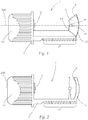
- Fig. 1 shows a first variant of a light source module 1, wherein a laser light source 3 and a spaced-apart lighting element 4, which is held in an optical element 9, are arranged on a carrier element 5.
- the laser light source 3 is, for example, a semiconductor laser in the form of a laser diode or a light source array with a plurality of laser diodes, including the necessary control electronics and cabling. If several laser light sources are provided, these can be color-matched, for example.
- the carrier element 5 is made of a heat-conducting material of a known type (e.g. as a heat sink, comprising a heat pipe), so it dissipates the heat generated during operation of the laser light source 3 and the luminous element 4.
- the carrier element 5 can be realized, for example, in “die-cast aluminum” or as a heat sink of known type comprising a heat pipe.
- Various metals, metallic alloys or anthracite or graphite-containing polymers are also possible.
- a variant is also possible in which the carrier element 5 is formed from glass material and contains embedded metal strips (e.g. copper) for heat conduction.
- the carrier element 5 can be made partially of transparent material which has irregularities such as microstructures, roughening or scattering bodies in its interior. As a result, light that leaves the laser light source 3 or the luminous element 4 is reflected and scattered and thus made visible from the outside, which can be used as a design element.
- the laser light source 3 is connected to a cooling element 15 for heat dissipation.
- the cooling element 15 serves to additionally dissipate the heat generated during operation of the laser light source 3.
- the cooling element 15 is arranged on the carrier element 5 or connected to it.
- the one-piece design of cooling element 15 and carrier element 5 ensures optimal heat transfer.
- the cooling element 15 is designed as a heat sink or as a ventilation device, so it either serves purely to dissipate heat, for example by increasing the surface area by means of cooling fins, or a cooling medium is actively supplied to the laser light source 3, for example by water cooling or a fan.
- the lighting element 4 is spherical; it is a phosphor converter which is excited by radiation with laser light to emit visible, preferably white, light.
- the lighting element 4 therefore emits white light in a functional manner.
- the spherical design is only one of several variants for designing the lighting element 4.
- the optical element 9 is made of a predominantly transparent material such as glass or plastic and has a receptacle for the lighting element 4, for example a blind hole 10 or a cavity enclosed on all sides by the optical element 9. As a result, the lighting element 4 is protected against environmental influences.
- At least one reflective reflection layer 8 is assigned to the luminous element 4 on a side facing away from the laser light source 3.
- the reflection layer 8 is designed as a coating on the side of the optical element 9 facing away from the laser light source 3.
- the coating is carried out, for example, by vapor deposition, painting or attaching a separate reflection element.
- the reflection layer 8 reflects light in the direction of the laser light source 3.
- the light emitted by the lighting element 4 in the direction facing away from the laser light source is thus made usable and at the same time optically preformed.
- an opaque absorption layer 12 is applied to the reflection layer 8.
- This absorption layer 12 serves as protection in order to prevent laser radiation or white light from escaping when the reflection layer 8 is irradiated (e.g. if it is made too thin in some places due to production).
- only one absorption layer 12 can also be provided - in this case the light is not optically preformed and reflected in the direction of the laser light source 3, but only shielded.
- that side of the optical element 9 which faces away from the laser light source 3 can be designed such that it has at least one focal point and the receptacle designed as a blind hole 10 is arranged in such a way that the luminous element 4 when inserted into the receptacle in one of these Focal points or in the vicinity.
- said outer surface of the optical element 9 (and thus also the reflection layer 8) preferably designed as a free-form surface. The execution of a free-form surface is known to the person skilled in the art.
- the outer surface and thus the reflection layer 9 applied thereon are designed such that light is reflected above, below and laterally in the vicinity of the lighting element 4 and thus quasi contributes to an enlargement of the light source or lighting element 4 - the lighting element 4 is in this variant is virtually surrounded by a light ring of reflected light.
- the reflection layer 8 therefore predominantly guides the light reflected by it past the lighting element.
- FIG. 1 Shown: An opaque diaphragm device 13 is arranged on the side of the optical element 9 facing the laser light source 3. This aperture device 13 is in Fig. 1 shown in dashed lines. In the exemplary embodiment shown, the diaphragm device 13 is arranged in a region below a horizontal plane 200 running through the lighting element 4. The horizontal plane 200 runs in Fig. 1 normal to the drawing plane and is shown as a dash-dotted line. Of course, other versions are possible depending on the desired light function.
- the diaphragm device 13 can be designed as desired, for example as an opaque coating or as a separate diaphragm that is glued on or applied in another way to the optical element 9 or held mechanically thereon.
- the diaphragm device 13 allows a light-dark transition to be generated, as a result of which various light functions such as low beam, fog light etc. can be implemented.
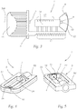
- FIG Fig. 2 Another variant of the light source module 1 is shown in FIG Fig. 2 shown.
- a concentrator optical element 7 arranged on the carrier element 5 and connected to it is provided, which is arranged on the side of the lighting element 4 facing away from the laser light source 3.
- the lighting element 4 is positioned via a holder, not defined in more detail, possibly surrounded by an encapsulation, which protects the lighting element 4 from environmental influences.
- the concentrator optical element 7 serves, on the one hand, to illuminate the light element in the assembled state when the light source module 1 is, for example, in a vehicle headlight 2 is installed in the main emission direction 100 of the vehicle headlight 2 (see 6 or 7 ) shield.
- a reflection layer 8 is also arranged, which reflects the light back in the direction of the laser light source 3 and preforms it optically.
- the surface of the concentrator optical element 7 can also be designed such that it has at least one focal point, the luminous element 4 preferably being arranged in this focal point.
- the surface can be designed as a free-form surface of a known type.
- the concentrator optical element 7 can be made of glass or plastic, for example - an absorption layer 12 may then have to be provided in addition to the reflection layer 8 in order to prevent the concentrator optical element 7 from radiating through.
- the concentrator optical element 7 is advantageously made of an opaque material such as metal or plastic, but in one variant it can also be made in one piece with the carrier element 5. This variant is in Fig. 2 shown.
- Fig. 3 shows a variant in which a light guide element 14 is arranged between the laser light source 3 and the lighting element 4, which is also arranged here in an optical element 9.
- the light-guiding element 14 consists of a light-guiding material, for example plastic or plexiglass, and can be of any shape, for example tubular, half-tubular (in the form of a half pipe), conical or cylindrical.
- Irregularities such as microstructures or interfering bodies inside the element can be provided in or on the light guide element 14, which scatter the laser light and thus make it visible from the outside.
- Exemplary shows Fig. 3 Wave structures 21 on the top of the light-guiding element 14.
- the light-source module can be used as a design or as a design element. For example, when using an additional colored, for example blue, laser light source or LED, which is directed onto the microstructures, a blue glow can be generated.
- the Fig. 4 and 5 show a perspective view of a light source module 1 according to the invention. There is also a lighting element 4 with one on it directed laser light source 3 shown. The laser beam 19 between the laser light source 3 and the lighting element 4 is outlined.
- the carrier element 5 consists of a carrier base 50, in which the laser light source 3 is arranged, and a carrier arm 51 with the luminous element 4 starting from the carrier base 50.
- the carrier arm is U-shaped starting from the carrier base 50 .
- the lighting element 4 is located at the point furthest away from the carrier base 50 on the side of the carrier arm 51 facing the laser light source 3.
- the lighting element 4 is similar in a concentrator optical element 7 Fig. 2 arranged.
- the carrier element 5 has an absorber area 18 which has an absorbing or non-reflecting surface.
- This absorber area 18 is used for safety: If the light source module 1 malfunctions for reasons not defined in more detail - for example if the lighting element 4 is destroyed or removed or the concentrator optical element 7 breaks - the laser beam 19 from the laser light source 3 does not strike a reflective one Surface or is directly in the environment of the light source module 1 or the vehicle headlight 2 (see 6 and 7 ) deflected, but hits the absorber area 18 and is absorbed there.
- sensor elements for detecting a malfunction of the laser light source 3 and / or the carrier element 5 can be arranged on the carrier element 5. Malfunctions are, for example, defects of the laser light source 3 or of the lighting element 4 described above or a breakage of the carrier element 5 due to mechanical action. In the event of a detected malfunction, the laser light source 3 can then be switched off. The recordings of the sensor elements are therefore to be evaluated accordingly or fed into the vehicle safety system.
- said sensor elements can be, for example, an optical sensor for detecting a deviation of the laser light emitted by the laser light source 3 from the correct beam direction, an optical sensor for detecting malfunctions of the lighting element 4 or a mechanical sensor for detecting damage to the carrier element 5 and / or the lighting element 4 and / or the optical element 9 or the concentrator optical element 7.
- An example is in Fig. 4 and 5 an optical sensor 16 for monitoring the laser beam 19 is shown.
- the optical sensor 16 can be a photocell, for example.
- the optical sensor 16 is positioned behind the concentrator optical element 7 such that it is hit by the laser beam 19 when the concentrator optical element 7 breaks. As mentioned above, a large number of other designs are also possible.
- the light source module 1 can have at least one safety switching device that prevents activation of the light source module 1 or the laser light source 3 of the light source module 1 before the light source module 1 has been installed in a vehicle headlight 2 or a reflector 6 or reflector adapter of a vehicle headlight 2.
- This can be a contact switch, for example, which only enables the laser light source 3 to be put into operation in the correct position in the vehicle headlight 2 or in the reflector 6 of a vehicle headlight.
- a coding resistor or a bridge which can be integrated in the cable harness or in the lighting unit (mechanical and / or electronic) and only enables commissioning when the vehicle headlight 2 or the light module 1 are installed in the vehicle.
- Such safety switching devices are not shown in the figures.
- Fig. 6 now shows a sectional view of a light source module 1, which is arranged in a vehicle headlight 2.
- the vehicle headlight 2 has a reflector 6, into which the light source module 1 can be inserted.
- the light source module 1 is designed such that the light-emitting element 4 is arranged in a focal point of the reflector 6 in the assembled state. In this way, optimal utilization of the light emitted by the lighting element 4 can be ensured.
- the light source module 1 is mounted such that the cooling element 15 associated with the laser light source 3 is arranged outside the reflector 6. Since the cooling element 15 is connected to the carrier element 5 in a heat-conducting manner, optimal heat dissipation from the reflector 6 is thereby ensured.
- the opaque reflection layer 8 of the optical element 9 ensures that no light in the main emission direction 100 of the vehicle headlight 2 is emitted and the laser light cannot escape in this direction. This is also ensured when the lighting element 4 is no longer in place.
- Fig. 6 it can be seen that in the main emission direction 100 of the vehicle headlight 2, light is emitted both directly from the lighting element 4 via the reflector 6 ("A" in Fig. 6 ) as well as light which is deflected from the lighting element 4 via the reflection layer 8 of the optical element 9 to the reflector 6 of the vehicle headlight 2 ("B" in Fig. 6 ).
- the means for detachably mounting the light source module 1 in the headlight 2 can include reference means, which in the present exemplary embodiment are designed as dowel pins that interact with dowel holes. More precisely, there are on the one hand on a flange integral with the carrier element 5 of the light source module 1, dowel pins 5 'and dowel holes 5 "and, on the other hand, on a flange of the reflector 6 of the headlight 2 dowel holes 6" and dowel pins 6'.
- a dowel pin 5 ' is provided on the module 1 or the carrier element 5 and a dowel pin 6' on the headlight 2, but of course other designs are possible in which, for example, only dowel pins are formed on the light source module 1 and only dowel holes are formed on the headlight or vice versa.
- FIG. 7 Another variant of a light source module 1 installed in a vehicle headlight 2 according to the embodiment in FIG Fig. 4 is in a perspective view in Fig. 7 shown.
- the light source module 1 is arranged therein in a reflector 6, design elements 20 being provided in addition to the light source module 1.
- the light source module 1 is in both variants shown along the main axis 300 (only in Fig. 6 shown) of the reflector 6 and anchored with means for detachable assembly - this can be, for example, locking elements that interact with corresponding locking receptacles in the reflector 6.
- the means for detachable mounting of the light source module 1 are preferably arranged on its carrier element 5.
- the light source module 1 and / or the laser light source 3 have reference means for referencing the light source module 1 and / or the laser light source 3 im Vehicle headlights 2 or in its reflector 6.
- the reference means can be designed differently - for example, according to a first variant, they can be guide devices which cooperate with corresponding guide receiving devices in the vehicle headlight 2 or in its reflector 6 or reflector adapter.
- rails can be provided in the opening through which the light source module 1 is introduced into the vehicle headlight 2, which cooperate with corresponding slots on the light source module 1 and up to e.g. lead to a stop.
- the reference means are designed as a reference plane on the laser light source 3 and / or the carrier element 4 with at least three contact surfaces, which interact with corresponding contact surface receptacles on the vehicle headlight 1, in particular on the reflector 6 of a vehicle headlight 1.
Landscapes
- Engineering & Computer Science (AREA)
- General Engineering & Computer Science (AREA)
- Physics & Mathematics (AREA)
- Optics & Photonics (AREA)
- Mechanical Engineering (AREA)
- Microelectronics & Electronic Packaging (AREA)
- Non-Portable Lighting Devices Or Systems Thereof (AREA)
- Arrangement Of Elements, Cooling, Sealing, Or The Like Of Lighting Devices (AREA)
- Fastening Of Light Sources Or Lamp Holders (AREA)
- Lighting Device Outwards From Vehicle And Optical Signal (AREA)
Description
- Die Erfindung betrifft ein Lichtquellenmodul für einen Fahrzeugscheinwerfer, wobei das Lichtquellenmodul zumindest eine Laserlichtquelle und zumindest ein durch Beleuchtung mit Laserlicht zur Ausstrahlung von sichtbarem Licht anregbares Leuchtelement, das durch die Laserlichtquelle bestrahlbar ist, aufweist, wobei die Laserlichtquelle und das Leuchtelement zueinander beabstandet auf einem Trägerelement angeordnet sind, wobei das Leuchtelement derart auf dem Trägerelement angeordnet ist, dass es im montierten Zustand in einem Brennpunkt eines Reflektors des Fahrzeugscheinwerfers anordenbar ist.
- Im Stand der Technik sind verschiedene Arten von Fahrzeugscheinwerfern bekannt, in die Lichtquellenmodule mit beispielsweise Entladungslampen oder Halogenlichtquellen eingebracht und befestigt werden können. Dazu sind üblicherweise entsprechende Aufnahmen in den Reflektoren oder Reflektoradaptern vorgesehen.
- Die heute üblichen Lichtquellenmodule enthalten jeweils eine Lichtquelle und eine Zündvorrichtung, die eine gemeinsame Baugruppe bilden und daher leicht und reproduzierbar montiert bzw. im Fall einer Fehlfunktion einfach getauscht werden können. Dabei ist sichergestellt, dass sich bei Einsetzen eines neuen Lichtquellenmoduls die Lichtquelle wieder an der richtigen Stelle - z.B. hinsichtlich des Reflektors - befindet.
- Aus Energiespargründen und um den Platzbedarf von Fahrzeugscheinwerfern zu verringern wird zunehmend der Einsatz von Laserlichtquellen wie Halbleiterlasern erprobt, da diese diesbezüglich von Vorteil sind. Um das Laserlicht für einen Fahrzeugscheinwerfer nutzbar zu machen wird dabei mit einer Laserlichtquelle ein Leuchtelement, ein sog. Phosphor, bestrahlt, der dadurch zur Abstrahlung von sichtbarem Licht angeregt wird. Derartige Lösungen zeigen
US 2011/0157865 A1 undUS 2011/0280033 A1 . Insbesondere zeigt dieUS 2011/0194302 A1 einen Scheinwerfer bzw. einen Projektor mit einer an einem Gehäuse angeordneten Laserdioden-Lichtquelle und einem Leuchtelement, das entweder unmittelbar auf dem Gehäuse der Leuchtdiode sitzt und in einem Scheinwerfer angeordnet ist oder in Abstand von der Laserdiode unter Zwischenschaltung einer Linse in dem Reflektor eines Projektors angeordnet ist. Dieses Dokument zeigt kein Trägerelement zur lösbaren Montage. Die Laserdiode scheint vielmehr zum Einlöten in der Anordnung bestimmt. - Das Dokument
WO 2006/066530 A1 zeigt ein mehrere LEDs enthaltendes Modul für einen Fahrzeugscheinwerfer und besitzt einen Kühlkörper, der mit einem Bajonettverschluss mit Verriegelungseinrichtungen in einem Fahrzeugscheinwerfer einsetzbar ist. - Das Dokument
JP 2012-009380 A US 2011/0.280.032 offenbart ein Lichtquellenmodul gemäß dem Oberbegriff des Anspruchs 1. - Bei Leuchteinheiten, welche einen Laser und ein Leuchtelement samt einer allfälligen Laserlichtführung aufweisen, treten verschiedene, zum Teil nicht oder nur mangelhaft gelöste Probleme auf, wobei besonders zu erwähnen wären: effiziente Kühlung von Laser und Phosphor, Austauschbarkeit einer in einem Scheinwerfer sitzenden Leuchteinheit, korrektes Justieren der Leuchteinheit in einem Scheinwerfer, korrektes Justieren des Lasers bezüglich des Phosphors.
- Es ist daher eine Aufgabe der Erfindung, ein Lichtquellenmodul bereit zu stellen, das mit einer Laserlichtquelle betrieben werden kann und welches hinsichtlich der Lösung der oben genannten Probleme eine Verbesserung darstellt.
- Diese Aufgabe wird mit einem eingangs erwähnten Lichtquellenmodul erfindungsgemäß dadurch gelöst, dass das Lichtquellenmodul an dem Trägerelement angeordnete Mittel zur lösbaren Montage in dem Fahrzeugscheinwerfer aufweist und das Trägerelement zumindest eine Trägerbasis mit zumindest einer Laserlichtquelle und zumindest einen von der Trägerbasis ausgehenden Trägerarm mit zumindest einem Leuchtelement aufweist, und der Trägerarm von der Trägerbasis ausgehend U-förmig ausgeführt ist, wobei das zumindest eine Leuchtelement an der von der Trägerbasis am weitesten entfernten Stelle auf der der Laserlichtquelle zugewandten Seite des Trägerarms angeordnet ist.
- Das erfindungsgemäße Lichtquellenmodul ermöglicht bei optimaler Ausnutzung des vom Leuchtelement ausgestrahlten Lichts eine standardisierte Laserlichtquelle für Fahrzeugscheinwerfer, wobei durch die gemeinsame Anordnung von Laserlichtquelle und Leuchtelement auf einem Trägerelement die Positioniergenauigkeit zwischen Laserlichtquelle und Leuchtelement sichergestellt ist. Das Lichtquellenmodul kann wie herkömmliche Module in Richtung der optischen Achse eines Fahrzeugscheinwerfers bzw. dessen Reflektors von hinten eingefügt werden. Dadurch ist auch ein leichter Einbau bzw. Austausch möglich, wobei dabei die reproduzierbare Positionierung insbesondere des Leuchtelements innerhalb des Fahrzeugscheinwerfers sichergestellt ist. Diese Austauschbarkeit ergibt eine ressourcenschonende, wirtschaftliche Handlungsmöglichkeit, zumal im Falle eines Defekts nicht der gesamte Scheinwerfer, sondern lediglich das Lichtquellenmodul ausgetauscht werden muss. Auch können so routinemäßige Kontrollen, z.B. des Phosphors, einfacher durchgeführt werden. Der Aufbau des Moduls erleichtert in besonderem Maß die Kühlung, sowohl der Laserlichtquelle als auch des Leuchtelements. Durch die U-förmige Ausführung ist der Bereich, in dem der Laserlichtstrahl verläuft, abgeschirmt.
- Vorteilhafterweise umfassen die Mittel zur lösbaren Montage Referenzmittel zum Referenzieren des Lichtquellenmoduls und/oder der Laserlichtquelle in einem Fahrzeugscheinwerfer, insbesondere einem Reflektor eines Fahrzeugscheinwerfers. Damit kann sichergestellt werden, dass beim Verbauen des Lichtquellenmoduls in einen Scheinwerfer die optimale Positionierung des Moduls bzw. dessen Leuchtelements reproduzierbar ist.
- In einer Variante der Erfindung sind die Referenzmittel als mit entsprechenden Führungsaufnahmevorrichtungen eines Fahrzeugscheinwerfers, insbesondere eines Reflektors eines Fahrzeugscheinwerfers, zusammenwirkende Führungsvorrichtungen ausgeführt.
- In einer weiteren Variante der Erfindung sind die Referenzmittel als auf der Laserlichtquelle und/oder dem Trägerelement ausgeführte Referenzebene mit zumindest drei Auflageflächen ausgeführt, die mit entsprechenden Auflageflächenaufnahmen am Fahrzeugscheinwerfer, insbesondere am Reflektor eines Fahrzeugscheinwerfers, zusammenwirken.
- In noch einer weiteren Variante der Erfindung sind die Referenzmittel als zumindest ein Passstift und zumindest ein Passloch ausgeführt, wobei der Passstift auf der Laserlichtquelle und/oder dem Trägerelement angeordnet sind und das Passloch auf einem Fahrzeugscheinwerfer angeordnet ist, oder umgekehrt.
- Das Trägerelement kann beliebig ausgeführt sein, beispielsweise aus Kunststoff. Günstigerweise ist das Trägerelement aus einem wärmeleitenden Material und/oder zumindest teilweise aus einem transparenten Material gefertigt. Dabei können verschiedene gebräuchliche Materialien verwendet werden, beispielsweise kann das Trägerelement in "Alu-Druckguß" oder als ein eine Heatpipe umfassender Kühlkörper bekannter Art realisiert werden. Möglich sind auch verschiedene Metalle, metallische Legierungen oder anthrazit-bzw. graphithältige Polymere. Das Material bzw. die Ausführung ist so zu wählen, dass ein Wärmeabtransport vom Leuchtelement weg gewährleistet ist.
- Als Laserlichtquelle können beispielsweise Halbleiterlaser bzw. Laserdioden bekannter Art verwendet werden, wobei die Wellenlänge des abgestrahlten Lichts im Bereich von 200 nm bis 450 nm liegt. Beispielsweise kann es sich auch um ein Lichtquellenarray mit mehreren Lichtquellen, insbesondere Laserdioden, handeln. Dabei kann eine Farbabstimmung zwischen den verschiedenen Lichtquellen vorgesehen werden. Bei dem Lichtelement handelt es sich beispielsweise um einen beliebigen Phosphor-Konverter, wobei allen diesen Materialien gemein ist, dass sie mit Laserlicht zur Emission von sichtbarem Licht insbesondere weißer Farbe anregbar sind.
- Über das Trägerelement kann so die während des Betriebs der Laserlichtquelle bzw. des Leuchtelements entstehende Wärme abgeleitet werden. Die Abwärme kann dabei durchaus beträchtlich sein, da Laserlichtquellen mit Leistungen von derzeit bis zu 3 W verwendet werden, wobei ein Teil der Leistung in Form von Wärme abgegeben wird. Die Wärmeableitung ist von Vorteil, da die Abstrahlungscharakteristik einer Laserdiode, wie sie hier zum Einsatz kommt, im Gegensatz zu LEDs stark von der Temperatur abhängig ist.
- Bei Ausführung des Trägerelements zumindest teilweise aus einem transparenten Material kann in Kombination mit im Trägerelement oder an dessen Oberfläche ausgeführten Unregelmäßigkeiten (Mikrostrukturen, Materialeinschlüsse, o.ä.) das eingestrahlte Laserlicht oder das vom Leuchtelement stammende Licht abgelenkt und damit sichtbar gemacht werden. Laser-Licht, welches unkollimiert die Laserlichtquelle verlässt, wird im transparenten Teil des Trägerelements gestreut und gespiegelt, damit das Licht außerhalb des Fahrzeugscheinwerfers wahrgenommen werden kann. Beispielsweise kann so bei Verwendung einer blauen Laserlichtquelle ein die Augen nicht gefährdendes blaues Leuchten erzeugt werden, das als Designelement eingesetzt werden kann.
- Vorteilhafterweise ist auf der von der Laserlichtquelle abgewandten Seite des Leuchtelements ein auf dem Trägerelement angeordnetes Konzentratoroptikelement vorgesehen, welches das Leuchtelement im montierten Zustand in Hauptabstrahlrichtung des Fahrzeugscheinwerfers abschirmt und/oder auf seiner dem Leuchtelement zugewandten Seite eine Reflexionsschicht aufweist. Das Konzentratoroptikelement kann dabei beispielsweise aus Glas gefertigt sein, das auf seiner von der Laserlichtquelle abgewandten Seite mit einer lichtundurchlässigen Beschichtung versehen ist.
- Das Konzentratoroptikelement kann weiters aus Kunststoff oder Metall gefertigt sein, die bevorzugt lichtundurchlässig sind. Dadurch wird verhindert, dass das vom Leuchtelement emittierte Licht unkontrolliert in Hauptabstrahlrichtung den Fahrzeugscheinwerfer verlässt und derart das Lichtbild beeinträchtigt. Außerdem dient das Konzentratoroptikelement gemäß dieser Variante als Sicherheitsvorkehrung: Es schirmt als Abdeckkappe das Laserlicht gegen die Umgebung ab und verhindert dessen Austritt und damit die Gefährdung unbeteiligter Verkehrsteilnehmer. Bei Vorsehen einer dem Leuchtelement zugewandten Reflexionsschicht wird das vom Leuchtelement allseitig (insbesondere in von der Laserlichtquelle wegführender Richtung) emittierte Licht nutzbar gemacht und gleichzeitig optisch vorgeformt - das Konzentratoroptikelement fungiert damit als Reflektor.
- In einer Variante der Erfindung ist das Leuchtelement in einem auf dem Trägerelement angeordnetem Optikelement, bevorzugt in einem Sackloch oder in einer Höhlung, angeordnet, wobei dem Optikelement zumindest auf einer von der Laserlichtquelle abgewandten Seite zumindest eine, Licht in Richtung der Laserlichtquelle reflektierende Reflexionsschicht und/oder zumindest eine lichtundurchlässige Absorptionsschicht zugeordnet ist. Die Reflexionsschicht und/oder die lichtundurchlässige Absorptionsschicht sind bevorzugt direkt auf dem Optikelement angebracht. Das Optikelement weist also eine Aufnahme für das Leuchtelement und eine Reflexionsschicht und/oder Absorptionsschicht in einem gemeinsamen Bauteil auf.
- Neben der Ausführung als Sackloch kann die Ausnehmung auch als Höhlung, also allseitig vom Optikelement umschlossen, ausgeführt sein. Dadurch wird das Leuchtelement vor Umgebungseinflüssen geschützt. Das Optikelement kann beispielsweise aus Glas oder transparentem Kunststoff ausgeführt sein, damit das Licht der Laserlichtquelle auf das Leuchtelement treffen kann. Bei Vorsehen einer lichtundurchlässigen Beschichtung wirkt das Optikelement (genauso wie das Konzentratoroptikelement) als Abdeckkappe für das Laserlicht und das vom Leuchtelement ausgestrahlte Licht. Diese lichtundurchlässige Beschichtung kann beispielsweise auch für Designzwecke verwendet werden, z.B. um Herstellerlogos zu platzieren.
- In einer weiteren Variante der Erfindung ist die der Laserlichtquelle zugewandte Seite des Optikelements zumindest teilweise, insbesondere aber in einem Bereich unter einer durch das Leuchtelement verlaufenden Horizontalebene, von einer lichtundurchlässigen Blendenvorrichtung, beispielsweise in Form einer lichtundurchlässigen Beschichtung, bedeckt. Die Blendenvorrichtung erlaubt die Erzeugung eines Hell-Dunkel-Übergangs, wodurch sich verschiedene Lichtfunktionen wie Abblendlicht, Nebellicht etc. realisieren lassen. Im Falle eines Abblendlichts ist es beispielsweise notwendig, dass das Leuchtelement scharf geometrisch und lichttechnisch abgegrenzt ist. Diesem Zweck dient die oben genannte Blendenvorrichtung, die beispielsweise als Lackierung, Bedampfung oder separates Bauteil ausgeführt ist. Die Blendenvorrichtung bewirkt zusammen mit entsprechend gestalteten Reflexionsbereichen, dass die im Optikelement reflektierte Lichtausstrahlung oberhalb des Leuchtelements austritt und damit für den Fahrzeugscheinwerfer nutzbar ist.
- Grundsätzlich ist die genannte Erfindung als Freistrahlkonzept umgesetzt, die Laserlichtquelle strahlt also direkt auf das Leuchtelement. In einer Variante der Erfindung ist zwischen der Laserlichtquelle und dem Leuchtelement zumindest ein Lichtleitelement angeordnet. Dieses Lichtleitelement besteht dabei aus einem lichtleitenden Material, beispielsweise Kunststoff (z.B. Plexiglas), und kann beliebig ausgeformt sein, beispielsweise röhren-, kegel- oder zylinderförmig. Auch eine Ausführung als trichterförmiges Konzentratorelement, beispielsweise aus Glas, ist möglich. Das Lichtleitelement kann auch mit Unregelmäßigkeiten (Mikrostrukturen, Aufrauhungen an der Oberfläche, Streukörper im Inneren, etc.) versehen sein, die das Laserlicht ablenken und so ein Leuchten des Lichtleitelements bewirken, was als Designelement verwendbar ist. Beispielsweise kann bei Verwendung einer blauen Laserlichtquelle derart ein blaues Leuchten erzeugt werden.
- Um die beim Betrieb der Laserlichtquelle entstehende Abwärme abzuleiten, ist vorteilhafterweise die Laserlichtquelle mit zumindest einem Kühlelement verbunden, das insbesondere als Kühlkörper und/oder Belüftungsvorrichtung ausgeführt ist. Günstigerweise ist das mit der Laserlichtquelle verbundene Kühlelement auf dem Trägerelement angeordnet. Das Kühlelement kann beispielsweise als Wasserkühlung, Ventilatoreinheit oder Heatpipe ausgeführt sein, möglich ist aber auch eine Ausführung beispielsweise mit Kühlrippen. In einer Variante ist das Trägerelement wie oben beschrieben wärmeleitend ausgeführt, so dass in Kombination mit dem gerade beschriebenen Kühlelement eine besonders effiziente Ableitung der durch das Lichtquellenmodul produzierten Abwärme sichergestellt ist.
- Fehlfunktionen des Lichtquellenmoduls, beispielsweise der Laserlichtquelle, können neben Nachteilen für den Betrieb auch zu einer Gefährdung anderer Verkehrsteilnehmer führen. Daher ist in einer Variante der Erfindung auf dem Trägerelement zumindest ein Sensorelement zur Erkennung einer Fehlfunktion der Laserlichtquelle und/oder der Trägerelements angeordnet. Bei dem Sensorelement kann es sich um zumindest eine der folgenden Sensorvorrichtungen handeln: optischer Sensor zur Detektion einer Abweichung des von der Laserlichtquelle ausgestrahlten Laserlichts von der ordnungsgemäßen Strahlrichtung; optischer Sensor zur Detektion von Fehlfunktionen des Leuchtelements; mechanischer Sensor zur Detektion einer Beschädigung des Trägerelements und/oder des Leuchtelements und/oder des Optikelements und/oder des Konzentratoroptikelements.
- Vorteilhafterweise weist das Trägerelement in dem Bereich um das Leuchtelement einen Absorberbereich mit einer absorbierenden bzw. nicht-reflektierenden Oberfläche auf. Damit kann eine zusätzliche Sicherheitsfunktion realisiert werden, da bei einer Fehlfunktion-wenn sich beispielsweise die Orientierung der Laserlichtquelle aufgrund einer Verstellung der Quelle oder womöglich eines Bruchs des Trägerelements verändert - bei Auftreffen des Laserstrahls abseits des Leuchtelements das Licht absorbiert und nicht unkontrolliert reflektiert wird. Eine derartige absorbierende bzw. nicht-reflektierende Oberfläche wird dazu günstigerweise in dem Bereich, in dem das Laserlicht bei Fehlfunktionen auftreffen kann, bzw. im Nahbereich des Leuchtelements realisiert.
- In einer Variante der Erfindung weist das Lichtquellenmodul zumindest eine Sicherheitsschaltvorrichtung auf, die ein Aktivieren des Lichtquellenmoduls bzw. der Laserlichtquelle des Lichtquellenmoduls vor erfolgtem Einbau des Lichtquellenmoduls in einen Fahrzeugscheinwerfer unterbindet. Dabei kann es sich beispielsweise um einen Kontaktschalter handeln, der die Inbetriebnahme der Laserlichtquelle erst in korrekter Position im Fahrzeugscheinwerfer bzw. im Reflektor eines Fahrzeugscheinwerfers freigibt. Eine weitere Möglichkeit sind ein Kodier-Widerstand oder eine Brücke welche im Kabelstrang oder in die lichttechnische Einheit integriert sein kann (mechanisch und/oder elektronisch) und die Inbetriebnahme erst freigibt, wenn der Scheinwerfer oder das Lichtmodul im Fahrzeug verbaut sind.
- Die Aufgabe der Erfindung wird weiters durch einen eingangs erwähnten Fahrzeugscheinwerfer mit zumindest einem Lichtquellenmodul nach einer der oben beschriebenen Varianten gelöst. In einer Variante der Erfindung ist zumindest ein Reflektor oder Reflektoradapter mit zumindest einer Aufnahme für das Lichtquellenmodul vorgesehen. Der derart ausgeführte Fahrzeugscheinwerfer ist dazu geeignet, die gesetzlichen Bestimmungen der ECE, SAE, CCC, usw. zu erfüllen.
- Im Folgenden wird die Offenbarung anhand eines nicht einschränkenden Ausführungsbeispiels, das in der Zeichnung dargestellt ist, näher erläutert. In dieser zeigt schematisch:
-
Fig. 1 eine Seitenansicht einer ersten Variante eines Lichtquellenmoduls; -
Fig. 2 eine Seitenansicht einer zweiten Variante eines Lichtquellenmoduls; -
Fig. 3 eine Seitenansicht eines erfindungsgemäßen Lichtquellenmoduls; -
Fig. 4 perspektivische Ansicht von schräg vorne einer vierten Variante des erfindungsgemäßen Lichtquellenmoduls; -
Fig. 5 eine perspektivische Ansicht von schräg hinten der Variante ausFig. 4 ; -
Fig. 6 eine seitliche Schnittansicht eines Fahrzeugscheinwerfers mit einem Lichtquellenmodul gemäßFig. 1 ; und -
Fig. 7 eine perspektivische Ansicht von schräg vorne eines Fahrzeugscheinwerfers mit einem Lichtquellenmodul gemäßFig. 4 . - Aus Gründen der Übersichtlichkeit sind gleiche Elemente in den verschiedenen Figuren jeweils mit demselben Bezugszeichen bezeichnet.
-
Fig. 1 zeigt eine erste Variante eines Lichtquellenmoduls 1, wobei eine Laserlichtquelle 3 und ein beabstandet angeordnetes Leuchtelement 4, das in einem Optikelement 9 gehalten ist, auf einem Trägerelement 5 angeordnet sind. Bei der Laserlichtquelle 3 handelt es sich beispielsweise um einen Halbleiterlaser in Form einer Laserdiode bzw. um ein Lichtquellenarray mit mehreren Laserdioden inkl. der notwendigen Ansteuerelektronik und Verkabelung. Beim Vorsehen mehrerer Laserlichtquellen können diese beispielsweise farbabgestimmt sein. - Das Trägerelement 5 ist aus einem wärmeleitenden Material bekannter Art gefertigt (z.B. als Kühlkörper, umfassend eine Heatpipe), führt also die beim Betrieb von Laserlichtquelle 3 und Leuchtelement 4 entstehende Wärme ab. Das Trägerelement 5 kann beispielsweise in "Alu-Druckguß" oder als eine Heatpipe umfassender Kühlkörper bekannter Art realisiert werden. Möglich sind auch verschiedene Metalle, metallische Legierungen oder anthrazit- bzw. graphithältige Polymere. Möglich ist auch eine Variante, bei der das Trägerelement 5 aus Glasmaterial ausgeformt ist und eingebettete Metallbänder (z.B. Kupfer) zur Wärmeleitung enthält.
- Zur Unterstützung sind auf der Unterseite des Trägerelements 5 in der Umgebung des Leuchtelements 4 Kühlrippen 17 vorgesehen. Das Trägerelement 5 kann teilweise aus transparentem Material gefertigt sein, das Unregelmäßigkeiten wie Mikrostrukturen, Aufrauhungen oder Streukörper in seinem Inneren aufweist. Dadurch wird Licht, das die Laserlichtquelle 3 oder das Leuchtelement 4 verlässt, gespiegelt und gestreut und so von außen sichtbar gemacht, was als Designelement verwendet werden kann.
- Zur Wärmeabführung ist die Laserlichtquelle 3 mit einem Kühlelement 15 verbunden. Das Kühlelement 15 dient zur zusätzlichen Abführung der beim Betrieb der Laserlichtquelle 3 entstehenden Wärme. Das Kühlelement 15 ist auf dem Trägerelement 5 angeordnet, bzw. mit diesem verbunden. Durch die einstückige Ausführung von Kühlelement 15 und Trägerelement 5 ist eine optimale Wärmeübertragung gegeben. Das Kühlelement 15 ist als Kühlkörper oder als Belüftungsvorrichtung ausgeführt, dient also entweder rein zum Abführen von Wärme, beispielsweise durch Oberflächenvergrößerung mittels Kühlrippen, oder es wird der Laserlichtquelle 3 aktiv ein Kühlmedium zugeführt, beispielsweise durch Wasserkühlung oder einen Ventilator.
- Das Leuchtelement 4 ist kugelförmig ausgeführt; es handelt sich um einen Phosphor-Konverter, der durch Bestrahlung mit Laserlicht zur Abstrahlung von sichtbarem, bevorzugt weißem Licht angeregt wird. Das Leuchtelement 4 spendet also funktionsgemäß weißes Licht. Die kugelförmige Ausführung ist nur eine von mehreren Varianten, das Leuchtelement 4 zu gestalten.
- Das Optikelement 9 ist aus einem überwiegend transparenten Material wie Glas oder Kunststoff ausgeführt und weist eine Aufnahme für das Leuchtelements 4 auf, beispielsweise ein Sackloch 10 oder eine allseitig von dem Optikelement 9 umschlossene Höhlung. Dadurch ist das Leuchtelement 4 gegen Umwelteinflüsse geschützt.
- Dem Leuchtelement 4 ist auf einer von der Laserlichtquelle 3 abgewandten Seite zumindest eine reflektierende Reflexionsschicht 8 zugeordnet. Die Reflexionsschicht 8 ist auf der von der Laserlichtquelle 3 abgewandten Seite des Optikelements 9 als Beschichtung ausgeführt. Die Beschichtung erfolgt beispielsweise durch Aufdampfen, Lackieren oder Befestigen eines separaten Reflexionselements. Die Reflexionsschicht 8 reflektiert Licht in Richtung der Laserlichtquelle 3. Damit wird vom Leuchtelement 4 in von der Laserlichtquelle abgewandter Richtung ausgestrahltes Licht nutzbar gemacht und gleichzeitig optisch vorgeformt. Auf der Reflexionsschicht 8 ist des Weiteren eine lichtundurchlässige Absorptionsschicht 12 aufgebracht. Diese Absorptionsschicht 12 dient als Schutz, um bei Durchstrahlen der Reflexionsschicht 8 (z.B., wenn diese produktionsbedingt an manchen Stellen zu dünn ausgeführt ist) ein Austreten von Laserstrahlung oder von weißem Licht zu verhindern. In einer Variante kann auch nur eine Absorptionsschicht 12 vorgesehen sein - in diesem Fall wird das Licht nicht optisch vorgeformt und in Richtung der Laserlichtquelle 3 reflektiert, sondern nur abgeschirmt.
- Je nach Ausführung der von der Laserlichtquelle 3 abgewandten Seite des Optikelements 9 und der Reflexionsschicht 8 können verschiedene Lichtfunktionen realisiert werden. Beispielsweise kann die von der Laserlichtquelle 3 abgewandte Seite des Optikelements 9 (also die Außenfläche) derart ausgeführt sein, dass sie zumindest einen Brennpunkt aufweist und die als Sackloch 10 ausgeführte Aufnahme so angeordnet ist, dass das Leuchtelement 4 bei Einbringung in die Aufnahme in einem dieser Brennpunkte bzw. in dessen Nähe zu liegen kommt. Dazu ist besagte Außenfläche des Optikelements 9 (und damit auch die Reflexionsschicht 8) bevorzugt als Freiformfläche ausgeführt. Das Ausführen einer Freiformfläche ist dem Fachmann bekannt.
- In einer Variante ist die Außenfläche und damit die darauf aufgebrachte Reflexionsschicht 9 so ausgeführt, dass Licht oberhalb, unterhalb und seitlich im Umkreis des Leuchtelements 4 reflektiert wird und derart quasi zu einer Vergrößerung der Lichtquelle bzw. des Leuchtelements 4 beiträgt - das Leuchtelement 4 ist in dieser Variante quasi von einem Lichtring an reflektiertem Licht umgeben. Die Reflexionsschicht 8 leitet also das von ihr reflektierte Licht überwiegend am Leuchtelement vorbei.
- Eine Variante ist strichliert in
Fig. 1 dargestellt: Auf der der Laserlichtquelle 3 zugewandten Seite des Optikelements 9 ist eine lichtundurchlässige Blendenvorrichtung 13 angeordnet. Diese Blendenvorrichtung 13 ist inFig. 1 strichliert eingezeichnet. Im dargestellten Ausführungsbeispiel ist die Blendenvorrichtung 13 in einem Bereich unter einer durch das Leuchtelement 4 verlaufenden Horizontalebene 200 angeordnet. Die Horizontalebene 200 verläuft inFig. 1 normal zur Zeichenebene und ist als strichpunktierte Linie eingezeichnet. Selbstverständlich sind je nach gewünschter Lichtfunktion auch andere Ausführungen möglich. - Die Blendenvorrichtung 13 kann beliebig ausgeführt sein, beispielsweise als lichtundurchlässige Beschichtung oder als separate Blende, die aufgeklebt oder auf eine andere Weise auf das Optikelement 9 aufgebracht bzw. an diesem mechanisch gehalten wird. Die Blendenvorrichtung 13 erlaubt die Erzeugung eines Hell-Dunkel-Übergangs, wodurch sich verschiedene Lichtfunktionen wie Abblendlicht, Nebellicht etc. realisieren lassen.
- Eine weitere Variante des Lichtquellenmoduls 1 ist in
Fig. 2 dargestellt. Darin ist anstatt des Optikelements 9 ausFig. 1 ein auf dem Trägerelement 5 angeordnetes und mit diesem verbundenes Konzentratoroptikelement 7 vorgesehen, das auf der von der Laserlichtquelle 3 abgewandten Seite des Leuchtelements 4 angeordnet ist. Das Leuchtelement 4 ist über eine nicht näher definierte Halterung positioniert, eventuell umgeben von einer Kapselung, die das Leuchtelement 4 vor Umwelteinflüssen schützt. - Das Konzentratoroptikelement 7 dient einerseits dazu, das Leuchtelement im montierten Zustand, wenn das Lichtquellenmodul 1 beispielsweise in einen Fahrzeugscheinwerfer 2 verbaut ist, in Hauptabstrahlrichtung 100 des Fahrzeugscheinwerfers 2 (siehe
Fig. 6 oder 7 ) abzuschirmen. Auf der dem Leuchtelement 4 zugewandten Seite des Konzentratoroptikelements 7 ist des Weiteren eine Reflexionsschicht 8 angeordnet, die das Licht in Richtung der Laserlichtquelle 3 zurückwirft und optisch vorformt. Zur optischen Vorformung kann die Oberfläche des Konzentratoroptikelements 7 ebenfalls derart ausgeführt sein, dass sie zumindest einen Brennpunkt hat, wobei das Leuchtelement 4 bevorzugt in diesem Brennpunkt angeordnet ist. Dazu kann die Oberfläche als Freiformfläche bekannter Art ausgeführt sein. Das Konzentratoroptikelement 7 kann beispielsweise aus Glas oder Kunststoff gefertigt sein - eventuell ist dann zusätzlich zu der Reflexionsschicht 8 eine Absorptionsschicht 12 vorzusehen, um eine Durchstrahlen des Konzentratoroptikelements 7 zu verhindern. Günstigerweise ist das Konzentratoroptikelement 7 aus einem lichtundurchlässigen Material wie Metall oder Kunststoff gefertigt, kann aber in einer Variante auch einstückig mit dem Trägerelement 5 gefertigt sein. Diese Variante ist inFig. 2 dargestellt. -
Fig. 3 zeigt eine Variante in der zwischen der Laserlichtquelle 3 und dem Leuchtelement 4, das hier ebenfalls in einem Optikelement 9 angeordnet ist, ein Lichtleitelement 14 angeordnet ist. Dies stellt eine Alternative zu dem Freistrahlkonzept aus denFig. 1 und 2 dar - das Laserlicht wird in dem Lichtleitelement 14 von der Laserlichtquelle 3 zum Leuchtelement 4 geführt. Das Lichtleitelement 14 besteht aus einem lichtleitendem Material, beispielsweise Kunststoff oder Plexiglas, und kann beliebig ausgeformt sein, beispielsweise röhren-, halbröhren- (in Form einer Halfpipe), kegel- oder zylinderförmig. Auch eine Ausführung als trichterförmiges Konzentratorelement, beispielsweise aus Glas, ist möglich. - In bzw. auf dem Lichtleitelement 14 können Unregelmäßigkeiten wie Mikrostrukturen oder Störkörper im Elementinneren vorgesehen sein, die das Laserlicht streuen und so von außen sichtbar machen. Beispielhaft zeigt
Fig. 3 Wellenstrukturen 21 auf der Oberseite des Lichtleitelements 14. Je nach geplantem Einsatzgebiet kann das Lichtquellenmodul so gestalterisch bzw. als Designelement verwendet werden. Beispielsweise kann bei Verwendung einer zusätzlichen färbigen, beispielsweise blauen, Laserlichtquelle oder LED, die auf die Mikrostrukturen gerichtet ist, ein blaues Leuchten erzeugt werden. - Die
Fign. 4 und 5 zeigen in perspektivischer Ansicht ein erfindungsgemäßes Lichtquellenmodul 1. Darin ist ebenfalls wieder ein Leuchtelement 4 mit einer darauf gerichteten Laserlichtquelle 3 dargestellt. Der Laserstrahl 19 zwischen Laserlichtquelle 3 und Leuchtelement 4 ist skizziert. - In dieser Variante besteht das Trägerelement 5 aus einer Trägerbasis 50, in der die Laserlichtquelle 3 angeordnet ist, und einem von der Trägerbasis 50 ausgehenden Trägerarm 51 mit dem Leuchtelement 4. Der Trägerarm ist gemäß dem dargestellten Ausführungsbeispiel von der Trägerbasis 50 ausgehend U-förmig ausgeführt. Das Leuchtelement 4 befindet sich an der von der Trägerbasis 50 am weitesten entfernten Stelle auf der der Laserlichtquelle 3 zugewandten Seite des Trägerarms 51.
- Das Leuchtelement 4 ist in einem Konzentratoroptikelement 7 ähnlich
Fig. 2 angeordnet. Im Bereich rund um das Leuchtelement 4 (inFig. 4 nicht sichtbar) weist das Trägerelement 5 einen Absorberbereich 18 auf, der eine absorbierende bzw. nicht-reflektierende Oberfläche aufweist. Dieser Absorberbereich 18 dient der Sicherheit: Wenn es aus nicht näher definierten Gründen zu einer Fehlfunktion des Lichtquellenmoduls 1 kommt - wenn also beispielsweise das Leuchtelement 4 zerstört oder entfernt wird oder das Konzentratoroptikelement 7 bricht - trifft der Laserstrahl 19 aus der Laserlichtquelle 3 nicht auf eine reflektierende Fläche oder wird direkt in die Umgebung des Lichtquellenmoduls 1 bzw. des Fahrzeugscheinwerfers 2 (sieheFig. 6 und 7 ) abgelenkt, sondern trifft auf den Absorberbereich 18 und wird dort absorbiert. - Daneben sind noch weitere Sicherheitsvorkehrungen möglich: Auf dem Trägerelement 5 können Sensorelemente zur Erkennung einer Fehlfunktion der Laserlichtquelle 3 und/oder des Trägerelements 5 angeordnet sein. Fehlfunktionen sind beispielsweise oben beschriebene Defekte der Laserlichtquelle 3 bzw. des Leuchtelements 4 oder ein Bruch des Trägerelements 5 aufgrund mechanischer Einwirkung. Im Fall einer erkannten Fehlfunktion kann dann eine Abschaltung der Laserlichtquelle 3 erfolgen. Die Aufzeichnungen der Sensorelemente sind also entsprechend auszuwerten bzw. in das Fahrzeug-Sicherheitssystem einzuspeisen.
- Bei besagten Sensorelementen kann es sich demzufolge beispielsweise um einen optischen Sensor zur Detektion einer Abweichung des von der Laserlichtquelle 3 ausgestrahlten Laserlichts von der ordnungsgemäßen Strahlrichtung, um einen optischen Sensor zur Detektion von Fehlfunktionen des Leuchtelements 4 oder um einen mechanischen Sensor zur Detektion einer Beschädigung des Trägerelements 5 und/oder des Leuchtelements 4 und/oder des Optikelements 9 bzw. des Konzentratoroptikelements 7 handeln. Beispielhaft ist in
Fign. 4 und 5 ein Optiksensor 16 zur Überwachung des Laserstrahls 19 eingezeichnet. Bei dem Optiksensor 16 kann es sich beispielsweise um eine Fotozelle handeln. Der Optiksensor 16 ist im dargestellten Ausführungsbeispiel so hinter dem Konzentratoroptikelement 7 positioniert, dass er dann vom Laserstrahl 19 getroffen wird, wenn das Konzentratoroptikelement 7 bricht. Wie oben erwähnt ist auch eine Vielzahl von anderen Ausführungen möglich. - Als zusätzliche Sicherheitsvorkehrung kann das Lichtquellenmodul 1 zumindest eine Sicherheitsschaltvorrichtung aufweisen, die ein Aktivieren des Lichtquellenmoduls 1 bzw. der Laserlichtquelle 3 des Lichtquellenmoduls 1 vor erfolgtem Einbau des Lichtquellenmoduls 1 in einen Fahrzeugscheinwerfer 2 bzw. einen Reflektor 6 oder Reflektoradapter eines Fahrzeugscheinwerfers 2 verhindert. Dabei kann es sich beispielsweise um einen Kontaktschalter handeln, der die Inbetriebnahme der Laserlichtquelle 3 erst in korrekter Position im Fahrzeugscheinwerfer 2 bzw. im Reflektor 6 eines Fahrzeugscheinwerfers freigibt. Eine weitere Möglichkeit sind ein Kodier-Widerstand oder eine Brücke welche im Kabelstrang oder in die lichttechnische Einheit integriert sein kann (mechanisch und/oder elektronisch) und die Inbetriebnahme erst freigibt, wenn der Fahrzeugscheinwerfer 2 oder das Lichtmodul 1 im Fahrzeug verbaut sind. Derartige Sicherheitsschaltvorrichtungen sind in den Figuren nicht dargestellt.
-
Fig. 6 zeigt nun in Schnittansicht ein Lichtquellenmodul 1, das in einem Fahrzeugscheinwerfer 2 angeordnet ist. Dabei handelt es sich um das Lichtquellenmodul 1 gemäßFig. 1 . Der Fahrzeugscheinwerfer 2 weist einen Reflektor 6 auf, in den das Lichtquellenmodul 1 einbringbar ist. Das Lichtquellenmodul 1 ist so ausgeführt, dass im montierten Zustand das Leuchtelement 4 in einem Brennpunkt des Reflektors 6 angeordnet ist. So lässt sich eine optimale Ausnutzung des vom Leuchtelement 4 ausgestrahlten Lichts sicherstellen. Im dargestellten Ausführungsbeispiel ist das Lichtquellenmodul 1 so montiert, dass das der Laserlichtquelle 3 zugeordnete Kühlelement 15 außerhalb des Reflektors 6 angeordnet ist. Da das Kühlelement 15 wärmeleitend mit dem Trägerelement 5 verbunden ist, wird dadurch eine optimale Ableitung der Wärme aus dem Reflektor 6 heraus sichergestellt. - Wie in
Fig. 6 erkennbar ist, wird durch die lichtundurchlässige Reflexionsschicht 8 des Optikelements 9 sichergestellt, dass kein Licht in Hauptabstrahlrichtung 100 des Fahrzeugscheinwerfers 2 abgestrahlt wird und auch das Laserlicht nicht in diese Richtung entweichen kann. Dies ist auch sichergestellt, wenn das Leuchtelement 4 nicht mehr an seinem Platz ist. InFig. 6 ist erkennbar, dass in Hauptabstrahlrichtung 100 des Fahrzeugscheinwerfers 2 Licht sowohl direkt vom Leuchtelement 4 über den Reflektor 6 abgestrahlt wird ("A" inFig. 6 ) als auch Licht, das vom Leuchtelement 4 über die Reflexionsschicht 8 des Optikelements 9 zum Reflektor 6 des Fahrzeugscheinwerfers 2 umgelenkt wird ("B" inFig. 6 ). - In
Fig. 6 ist weiters gezeigt, dass die Mittel zur lösbaren Montage des Lichtquellenmoduls 1 in dem Scheinwerfer 2 Referenzmittel umfassen kann, die im vorliegenden Ausführungsbeispiel als Passstifte ausgebildet sind, die mit Passlöchern zusammenwirken. Genauer gesagt, sind einerseits an einem mit dem Trägerelement 5 des Lichtquellenmoduls 1 einstückigen Flansch Passstifte 5' und Passlöcher 5" und andererseits an einem Flansch des Reflektors 6 des Scheinwerfers 2 Passlöcher 6" und Passstifte 6' vorhanden. Im vorliegenden Fall ist ein Passstift 5' am Modul 1 bzw. dem Trägerelement 5 und ein Passstift 6' am Scheinwerfer 2 vorgesehen, doch sind selbstverständlich andere Ausführungen möglich, bei welchen z.B. an dem Lichtquellenmodul 1 ausschließlich Passstifte und an dem Scheinwerfer ausschließlich Passlöcher ausgebildet sind bzw. umgekehrt. - Zusätzlich zu den Referenzmitteln, hier den Passstiften und den Passlöchern können natürlich noch weitere Mittel zur lösbaren Montage vorgesehen sein, wie Klammern, Schnappverbindungen etc.
- Eine weitere Variante eines in einem Fahrzeugscheinwerfer 2 verbauten Lichtquellenmoduls 1 gemäß der Ausführungsform in
Fig. 4 ist in einer perspektivischen Ansicht inFig. 7 dargestellt. Darin ist das Lichtquellenmodul 1 in einem Reflektor 6 angeordnet, wobei neben dem Lichtquellenmodul 1 Designelemente 20 vorgesehen sind. - Das Lichtquellenmodul 1 wird in beiden dargestellten Varianten entlang der Hauptachse 300 (nur in
Fig. 6 dargestellt) des Reflektors 6 eingeführt und mit Mitteln zur lösbaren Montage verankert - dabei kann es sich beispielsweise um Rastelemente handeln, die mit entsprechenden Rastaufnahmen im Reflektor 6 zusammenwirken. Die Mittel zur lösbaren Montage des Lichtquellenmoduls 1 sind bevorzugt an dessen Trägerelement 5 angeordnet. Aus dem Stand der Technik ist eine Vielzahl solcher Lösungen bekannt, die daher hier nicht näher ausgeführt werden. - Um sicherzustellen, dass beim Einbau bzw. bei einem Wechsel des Lichtquellenmoduls 1 die optimale Positionierung des Moduls bzw. seines Leuchtelements 4 sichergestellt sind, weisen das Lichtquellenmodul 1 und/oder die Laserlichtquelle 3 Referenzmittel zum Referenzieren des Lichtquellenmoduls 1 und/oder der Laserlichtquelle 3 im Fahrzeugscheinwerfer 2 bzw. in dessen Reflektor 6 auf.
- Die Referenzmittel können verschieden ausgeführt sein - beispielsweise kann es sich gemäß einer ersten Variante um Führungsvorrichtungen handeln, die mit entsprechenden Führungsaufnahmevorrichtungen im Fahrzeugscheinwerfer 2 bzw. in dessen Reflektor 6 oder Reflektoradapter zusammenwirken. Dazu können in der Öffnung, durch die das Lichtquellenmodul 1 in den Fahrzeugscheinwerfer 2 eingebracht wird, Schienen vorgesehen sein, die mit entsprechenden Schlitzen am Lichtquellenmodul 1 zusammenwirken und dieses bis z.B. zu einem Rastanschlag führen. Derartige Lösungen sind im Stand der Technik bekannt und hier deshalb nicht näher ausgeführt.
- In einer Variante sind die Referenzmittel als auf der Laserlichtquelle 3 und/oder dem Trägerelement 4 ausgeführte Referenzebene mit zumindest drei Auflageflächen ausgeführt, die mit entsprechenden Auflagenflächenaufnahmen am Fahrzeugscheinwerfer 1, insbesondere am Reflektor 6 eines Fahrzeugscheinwerfers 1, zusammenwirken.
Claims (18)
- Lichtquellenmodul (1) für einen Fahrzeugscheinwerfer (2), wobei das Lichtquellenmodul (1) zumindest eine Laserlichtquelle (3) und zumindest ein durch Beleuchtung mit Laserlicht zur Ausstrahlung von sichtbarem Licht anregbares Leuchtelement (4), das durch die Laserlichtquelle (3) bestrahlbar ist, aufweist, wobei die Laserlichtquelle (3) und das Leuchtelement (4) zueinander beabstandet auf einem Trägerelement (5) angeordnet sind, wobei das Leuchtelement (4) derart auf dem Trägerelement (5) angeordnet ist, dass es im montierten Zustand in einem Brennpunkt eines Reflektors (6) des Fahrzeugscheinwerfers (2) anordenbar ist, dadurch gekennzeichnet, dass das Lichtquellenmodul (1) an dem Trägerelement (5) angeordnete Mittel (5', 6'; 5", 6") zur lösbaren Montage in dem Fahrzeugscheinwerfer (2) aufweist und das Trägerelement (5) zumindest eine Trägerbasis (50) mit zumindest einer Laserlichtquelle (3) und zumindest einen von der Trägerbasis (50) ausgehenden Trägerarm (51) mit zumindest einem Leuchtelement (4) aufweist, und der Trägerarm (51) von der Trägerbasis (50) ausgehend U-förmig ausgeführt ist, wobei das zumindest eine Leuchtelement (4) an der von der Trägerbasis (50) am weitesten entfernten Stelle auf der der Laserlichtquelle (3) zugewandten Seite des Trägerarms (51) angeordnet ist.
- Lichtquellenmodul (1) nach Anspruch 1, dadurch gekennzeichnet, dass die Mittel zur lösbaren Montage Referenzmittel (5', 6'; 5", 6") zum Referenzieren des Lichtquellenmoduls (1) und/oder der Laserlichtquelle (3) in einem Fahrzeugscheinwerfer (2), insbesondere einem Reflektor (6) eines Fahrzeugscheinwerfers (2), umfassen.
- Lichtquellenmodul (1) nach Anspruch 2, dadurch gekennzeichnet, dass die Referenzmittel als mit entsprechenden Führungsaufnahmevorrichtungen in einem Fahrzeugscheinwerfer (2), insbesondere einem Reflektor (6) eines Fahrzeugscheinwerfers (2), zusammenwirkende Führungsvorrichtungen ausgeführt sind.
- Lichtquellenmodul (1) nach Anspruch 2, dadurch gekennzeichnet, dass die Referenzmittel als auf der Laserlichtquelle (3) und/oder dem Trägerelement (4) ausgeführte Referenzebene mit zumindest drei Auflageflächen ausgeführt sind, die mit entsprechenden Auflageflächenaufnahmen am Fahrzeugscheinwerfer (2), insbesondere am Reflektor (6) eines Fahrzeugscheinwerfers (2), zusammenwirken.
- Lichtquellenmodul (1) nach Anspruch 2 oder 3, dadurch gekennzeichnet, dass die Referenzmittel als zumindest ein Passstift und zumindest ein Passloch ausgeführt sind, wobei der Passstift auf der Laserlichtquelle (3) und/oder dem Trägerelement (5) angeordnet sind und das Passloch auf einem Fahrzeugscheinwerfer (2) angeordnet ist, oder umgekehrt.
- Lichtquellenmodul (1) nach einem der Ansprüche 1 bis 5, dadurch gekennzeichnet, dass das Trägerelement (5) aus einem wärmeleitenden Material und/oder zumindest teilweise aus einem transparenten Material gefertigt ist.
- Lichtquellenmodul (1) nach einem der Ansprüche 1 bis 6, dadurch gekennzeichnet, dass auf der von der Laserlichtquelle (3) abgewandten Seite des Leuchtelements (4) ein auf dem Trägerelement (5) angeordnetes Konzentratoroptikelement (7) vorgesehen ist, welches das Leuchtelement (4) im montierten Zustand in Hauptabstrahlrichtung (100) des Fahrzeugscheinwerfers (2) abschirmt und/oder auf seiner dem Leuchtelement (4) zugewandten Seite eine Reflexionsschicht (8) aufweist.
- Lichtquellenmodul (1) nach einem der Ansprüche 1 bis 9, dadurch gekennzeichnet, dass das Leuchtelement (4) in einem auf dem Trägerelement (5) angeordnetem Optikelement (9), bevorzugt in einem Sackloch (10) oder in einer Höhlung, angeordnet ist, wobei dem Optikelement (9) zumindest auf einer von der Laserlichtquelle (3) abgewandten Seite zumindest eine, Licht in Richtung der Laserlichtquelle (3) reflektierende Reflexionsschicht (8) und/oder zumindest eine lichtundurchlässige Absorptionsschicht (12) zugeordnet ist.
- Lichtquellenmodul (1) nach Anspruch 8, dadurch gekennzeichnet, dass die der Laserlichtquelle (3) zugewandte Seite des Optikelements (9) zumindest teilweise, insbesondere aber in einem Bereich unter einer durch das Leuchtelement (4) verlaufenden Horizontalebene (200), von einer lichtundurchlässigen Blendenvorrichtung (13), beispielsweise in Form einer lichtundurchlässigen Beschichtung, bedeckt ist.
- Lichtquellenmodul (1) nach einem der Ansprüche 1 bis 9, dadurch gekennzeichnet, dass zwischen der Laserlichtquelle (3) und dem Leuchtelement (4) zumindest ein Lichtleitelement (14) angeordnet ist.
- Lichtquellenmodul (1) nach einem der Ansprüche 1 bis 10, dadurch gekennzeichnet, dass die Laserlichtquelle (3) mit zumindest einem Kühlelement (15) verbunden ist, das insbesondere als Kühlkörper und/oder Belüftungsvorrichtung ausgeführt ist.
- Lichtquellenmodul (1) nach Anspruch 11, dadurch gekennzeichnet, dass das mit der Laserlichtquelle (3) verbundene Kühlelement (15) auf dem Trägerelement (5) angeordnet ist.
- Lichtquellenmodul (1) nach einem der Ansprüche 1 bis 12, dadurch gekennzeichnet, dass auf dem Trägerelement (5) zumindest ein Sensorelement (16) zur Erkennung einer Fehlfunktion der Laserlichtquelle (3) und/oder des Trägerelements (5) angeordnet ist.
- Lichtquellenmodul (1) nach Anspruch 13, dadurch gekennzeichnet, dass es sich bei dem Sensorelement (16) um zumindest eine der folgenden Sensorvorrichtungen handelt: optischer Sensor zur Detektion einer Abweichung des von der Laserlichtquelle (3) ausgestrahlten Laserlichts von der ordnungsgemäßen Strahlrichtung; optischer Sensor zur Detektion von Fehlfunktionen des Leuchtelements (4); mechanischer Sensor zur Detektion einer Beschädigung des Trägerelements (5) und/oder des Leuchtelements (4) und/oder des Optikelements (9) und/oder des Konzentratoroptikelements (7).
- Lichtquellenmodul (1) nach einem der Ansprüche 1 bis 14, dadurch gekennzeichnet, dass das Trägerelement (5) in dem Bereich um das Leuchtelement (4) einen Absorberbereich (18) mit einer absorbierenden bzw. nicht-reflektierenden Oberfläche aufweist.
- Lichtquellenmodul (1) nach einem der Ansprüche 1 bis 15, dadurch gekennzeichnet, dass das Lichtquellenmodul (1) zumindest eine Sicherheitsschaltvorrichtung aufweist, die ein Aktivieren des Lichtquellenmoduls (1) bzw. der Laserlichtquelle (3) des Lichtquellenmoduls (1) vor erfolgtem Einbau des Lichtquellenmoduls (1) in einen Fahrzeugscheinwerfer (2) unterbindet.
- Fahrzeugscheinwerfer (2) mit zumindest einem Lichtquellenmodul (1) nach einem der Ansprüche 1 bis 16.
- Fahrzeugscheinwerfer (2) nach Anspruch 17, dadurch gekennzeichnet, dass zumindest ein Reflektor (6) oder Reflektoradapter mit zumindest einer Aufnahme für das Lichtquellenmodul (1) vorgesehen ist.
Priority Applications (1)
| Application Number | Priority Date | Filing Date | Title |
|---|---|---|---|
| EP15196257.8A EP3021041B1 (de) | 2012-03-12 | 2013-03-12 | Lichtquellenmodul für einen fahrzeugscheinwerfer |
Applications Claiming Priority (2)
| Application Number | Priority Date | Filing Date | Title |
|---|---|---|---|
| ATA50073/2012A AT512588B1 (de) | 2012-03-12 | 2012-03-12 | Lichtquellenmodul mit Laserlichtquelle sowie Fahrzeugscheinwerfer |
| PCT/AT2013/050064 WO2013134807A1 (de) | 2012-03-12 | 2013-03-12 | Standardlichtquelle laser-diode |
Related Child Applications (2)
| Application Number | Title | Priority Date | Filing Date |
|---|---|---|---|
| EP15196257.8A Division EP3021041B1 (de) | 2012-03-12 | 2013-03-12 | Lichtquellenmodul für einen fahrzeugscheinwerfer |
| EP15196257.8A Division-Into EP3021041B1 (de) | 2012-03-12 | 2013-03-12 | Lichtquellenmodul für einen fahrzeugscheinwerfer |
Publications (2)
| Publication Number | Publication Date |
|---|---|
| EP2800677A1 EP2800677A1 (de) | 2014-11-12 |
| EP2800677B1 true EP2800677B1 (de) | 2020-07-01 |
Family
ID=48095446
Family Applications (2)
| Application Number | Title | Priority Date | Filing Date |
|---|---|---|---|
| EP15196257.8A Active EP3021041B1 (de) | 2012-03-12 | 2013-03-12 | Lichtquellenmodul für einen fahrzeugscheinwerfer |
| EP13716169.1A Active EP2800677B1 (de) | 2012-03-12 | 2013-03-12 | Standardlichtquelle laser-diode |
Family Applications Before (1)
| Application Number | Title | Priority Date | Filing Date |
|---|---|---|---|
| EP15196257.8A Active EP3021041B1 (de) | 2012-03-12 | 2013-03-12 | Lichtquellenmodul für einen fahrzeugscheinwerfer |
Country Status (6)
| Country | Link |
|---|---|
| US (1) | US9664351B2 (de) |
| EP (2) | EP3021041B1 (de) |
| JP (1) | JP6195124B2 (de) |
| CN (1) | CN104159786B (de) |
| AT (1) | AT512588B1 (de) |
| WO (1) | WO2013134807A1 (de) |
Families Citing this family (30)
| Publication number | Priority date | Publication date | Assignee | Title |
|---|---|---|---|---|
| AT513816B1 (de) | 2012-12-20 | 2015-11-15 | Zizala Lichtsysteme Gmbh | Lichtführungseinheit für eine Leuchteinheit eines Scheinwerfers sowie Leuchteinheit und Schweinwerfer |
| FR3007820B1 (fr) * | 2013-06-28 | 2017-09-08 | Valeo Vision | Module optique securise pour vehicule automobile comprenant une source laser |
| KR101533231B1 (ko) * | 2013-10-08 | 2015-07-02 | 에스엘 주식회사 | 차량용 램프의 방열 장치 |
| CN104654157A (zh) * | 2013-11-19 | 2015-05-27 | 丹阳市中远车灯有限公司 | 汽车前照灯 |
| DE102014202943A1 (de) | 2014-02-18 | 2015-08-20 | Osram Gmbh | Beleuchtungsvorrichtung mit Primärlichtquelle und Leuchtstoffvolumen |
| DE102014205294A1 (de) * | 2014-03-21 | 2015-09-24 | Automotive Lighting Reutlingen Gmbh | Beleuchtungseinrichtung |
| JP6511766B2 (ja) * | 2014-10-15 | 2019-05-15 | 日亜化学工業株式会社 | 発光装置 |
| DE102014226661A1 (de) * | 2014-12-19 | 2016-06-23 | Osram Gmbh | Leuchtvorrichtung |
| DE102015001695A1 (de) | 2015-02-10 | 2016-08-11 | Audi Ag | Beleuchtungsvorrichtung für einen Scheinwerfer eines Kraftfahrzeugs sowie Verfahren zum Betreiben einer Beleuchtungsvorrichtung |
| JP2016177923A (ja) * | 2015-03-19 | 2016-10-06 | ウシオ電機株式会社 | 蛍光光源装置 |
| US20180203297A1 (en) * | 2015-03-19 | 2018-07-19 | Mitsubishi Electric Corporation | Surface light source device and liquid crystal display device |
| DE102015104506A1 (de) * | 2015-03-25 | 2016-09-29 | Hella Kgaa Hueck & Co. | Beleuchtungsvorrichtung für Fahrzeuge |
| DE102015104499A1 (de) * | 2015-03-25 | 2016-09-29 | Hella Kgaa Hueck & Co. | Beleuchtungsvorrichtung für Fahrzeuge |
| KR101847932B1 (ko) * | 2015-04-23 | 2018-04-11 | 엘지전자 주식회사 | 발광모듈 |
| FR3038738B1 (fr) * | 2015-07-08 | 2017-08-11 | Valeo Vision | Dispositif optique comportant au moins un convertisseur de longueur d’onde, module lumineux et dispositif d’eclairage pour vehicule automobile comportant un tel dispositif |
| JP6741753B2 (ja) * | 2015-08-24 | 2020-08-19 | ルミレッズ ホールディング ベーフェー | 車両ヘッドライトのための照明デバイス |
| CN105215548B (zh) * | 2015-10-26 | 2017-09-12 | 惠州市杰普特电子技术有限公司 | 激光焊接装置 |
| DE102015120223A1 (de) | 2015-11-23 | 2017-05-24 | Dr. Ing. H.C. F. Porsche Aktiengesellschaft | Lichtleitelement für einen Fahrzeugscheinwerfer |
| CN105570790B (zh) * | 2015-11-25 | 2019-02-01 | 全普光电科技(上海)有限公司 | 激光车前灯 |
| CZ2015890A3 (cs) | 2015-12-11 | 2017-06-28 | Varroc Lighting Systems, s.r.o. | Světelné zařízení, zejména signální svítilna pro motorová vozidla |
| DE102016005880A1 (de) * | 2016-05-13 | 2017-11-16 | Man Truck & Bus Ag | Leuchte mit wenigstens einer Leuchtdiode (LED), insbesondere Frontscheinwerfer mit Tagfahrlicht für ein Kraftfahrzeug |
| DE102016117411B4 (de) * | 2016-09-15 | 2020-03-26 | Varroc Lighting Systems, s.r.o. | System zur Beleuchtung für ein Kraftfahrzeug mit einer Laserlichtquelle |
| CZ309003B6 (cs) | 2017-01-24 | 2021-11-18 | Varroc Lighting Systems, s.r.o. | Světelné zařízení, zejména projektorový systém světlometu pro motorová vozidla |
| FR3062451B1 (fr) * | 2017-01-27 | 2019-03-29 | Peugeot Citroen Automobiles Sa | Dispositif d’eclairage a masque a motifs en pointe de diamant |
| US10935201B2 (en) * | 2017-03-02 | 2021-03-02 | Honda Motor Co., Ltd. | Lighting apparatus disposition structure for saddle riding vehicle |
| DE202017103875U1 (de) * | 2017-06-29 | 2018-10-02 | Automotive Lighting Reutlingen Gmbh | Beleuchtungseinrichtung für ein Kraftfahrzeug |
| DE102017122560A1 (de) * | 2017-09-28 | 2019-03-28 | Automotive Lighting Reutlingen Gmbh | LED-Scheinwerfermodul |
| CN108087809B (zh) * | 2018-01-11 | 2023-11-17 | 乐山师范学院 | 故障自检自动开闭路灯 |
| CZ310094B6 (cs) | 2019-12-12 | 2024-08-07 | PO LIGHTING CZECH s.r.o | Osvětlovací zařízení vozidla s laserovým zdrojem záření |
| CN112903096A (zh) * | 2021-03-25 | 2021-06-04 | 安图实验仪器(郑州)有限公司 | 一种标准光源装置 |
Citations (1)
| Publication number | Priority date | Publication date | Assignee | Title |
|---|---|---|---|---|
| JP2012009380A (ja) * | 2010-06-28 | 2012-01-12 | Sharp Corp | 発光装置、照明装置、車両用前照灯、および発光装置の製造方法 |
Family Cites Families (30)
| Publication number | Priority date | Publication date | Assignee | Title |
|---|---|---|---|---|
| US3404350A (en) * | 1964-06-02 | 1968-10-01 | Arthur M. Muncheryan | Directed-beam portable laser system |
| EP1126208B1 (de) * | 2000-02-17 | 2005-05-11 | Denso Corporation | Beleuchtungsgerät mit Entladungslampe und entsprechende Montageanordnung |
| JP4452391B2 (ja) * | 2000-09-22 | 2010-04-21 | スタンレー電気株式会社 | Led灯具 |
| JP4124445B2 (ja) * | 2003-02-03 | 2008-07-23 | 株式会社小糸製作所 | 光源及び車両用前照灯 |
| US7094362B2 (en) * | 2003-10-29 | 2006-08-22 | General Electric Company | Garnet phosphor materials having enhanced spectral characteristics |
| JP4047266B2 (ja) * | 2003-11-19 | 2008-02-13 | 株式会社小糸製作所 | 灯具 |
| US7456805B2 (en) * | 2003-12-18 | 2008-11-25 | 3M Innovative Properties Company | Display including a solid state light device and method using same |
| JP2006073202A (ja) * | 2004-08-31 | 2006-03-16 | Nichia Chem Ind Ltd | 発光装置 |
| DE102004062990A1 (de) * | 2004-12-22 | 2006-07-06 | Patent-Treuhand-Gesellschaft für elektrische Glühlampen mbH | Beleuchtungseinrichtung mit mindestens einer Leuchtdiode und Fahrzeugscheinwerfer |
| KR100715403B1 (ko) * | 2005-09-21 | 2007-05-09 | 현대자동차주식회사 | 차량용 와셔액 경고등 점등장치 |
| DE102006029204A1 (de) * | 2006-06-26 | 2008-01-17 | Osram Opto Semiconductors Gmbh | Anordnung mit einem Lichtleiter |
| DE202006018081U1 (de) * | 2006-11-28 | 2007-02-08 | Patent-Treuhand-Gesellschaft für elektrische Glühlampen mbH | Beleuchtungseinheit für Fahrzeugscheinwerfer und Fahrzeugscheinwerfer |
| DE102007050924B4 (de) | 2007-10-23 | 2009-11-26 | Oechsler Ag | LED-bestückter Leuchtenmodul, insbesondere für Kraftfahrzeuge |
| WO2009115976A1 (en) * | 2008-03-20 | 2009-09-24 | Koninklijke Philips Electronics N.V. | Illumination system comprising a luminescent element with a heat sink |
| JP2011054759A (ja) * | 2009-09-02 | 2011-03-17 | Sharp Corp | 波長変換部材の保持部材とその製造方法、波長変換部材の放熱構造、発光装置 |
| JP5122542B2 (ja) * | 2009-09-15 | 2013-01-16 | シャープ株式会社 | 発光装置、照明装置および光検知器 |
| JP4975797B2 (ja) * | 2009-10-14 | 2012-07-11 | シャープ株式会社 | 照明装置、車両用灯具および車両 |
| JP4991834B2 (ja) * | 2009-12-17 | 2012-08-01 | シャープ株式会社 | 車両用前照灯 |
| JP4991001B2 (ja) | 2009-12-28 | 2012-08-01 | シャープ株式会社 | 照明装置 |
| JP5232815B2 (ja) * | 2010-02-10 | 2013-07-10 | シャープ株式会社 | 車両用前照灯 |
| JP5577138B2 (ja) * | 2010-04-08 | 2014-08-20 | スタンレー電気株式会社 | 車両用前照灯 |
| JP5155361B2 (ja) * | 2010-05-12 | 2013-03-06 | シャープ株式会社 | 導光部材、レーザ導光構造体、レーザ照射装置および光源装置 |
| US20110280033A1 (en) | 2010-05-17 | 2011-11-17 | Sharp Kabushiki Kaisha | Light-emitting device, illumination device, and vehicle headlamp |
| JP2011243369A (ja) * | 2010-05-17 | 2011-12-01 | Sharp Corp | 発光装置、照明装置および車両用前照灯 |
| JP5788149B2 (ja) * | 2010-06-18 | 2015-09-30 | 東芝ライテック株式会社 | 発光装置及び照明装置 |
| JP5798722B2 (ja) * | 2010-06-25 | 2015-10-21 | シャープ株式会社 | 発光装置および照明装置 |
| JP5781838B2 (ja) * | 2010-08-25 | 2015-09-24 | スタンレー電気株式会社 | 車両用の光源装置および灯具 |
| JP2012174551A (ja) * | 2011-02-22 | 2012-09-10 | Harison Toshiba Lighting Corp | 発光装置 |
| DE102011007123B4 (de) | 2011-04-11 | 2022-02-17 | Osram Gmbh | Halbleiter-Glühlampen-Retrofitlampe |
| JP5895331B2 (ja) * | 2011-12-20 | 2016-03-30 | スタンレー電気株式会社 | 発光装置、車両用灯具及び車両 |
-
2012
- 2012-03-12 AT ATA50073/2012A patent/AT512588B1/de not_active IP Right Cessation
-
2013
- 2013-03-12 CN CN201380013955.4A patent/CN104159786B/zh active Active
- 2013-03-12 EP EP15196257.8A patent/EP3021041B1/de active Active
- 2013-03-12 JP JP2014561229A patent/JP6195124B2/ja not_active Expired - Fee Related
- 2013-03-12 US US14/382,255 patent/US9664351B2/en active Active
- 2013-03-12 WO PCT/AT2013/050064 patent/WO2013134807A1/de not_active Ceased
- 2013-03-12 EP EP13716169.1A patent/EP2800677B1/de active Active
Patent Citations (1)
| Publication number | Priority date | Publication date | Assignee | Title |
|---|---|---|---|---|
| JP2012009380A (ja) * | 2010-06-28 | 2012-01-12 | Sharp Corp | 発光装置、照明装置、車両用前照灯、および発光装置の製造方法 |
Also Published As
| Publication number | Publication date |
|---|---|
| JP2015513778A (ja) | 2015-05-14 |
| US9664351B2 (en) | 2017-05-30 |
| CN104159786A (zh) | 2014-11-19 |
| EP3021041B1 (de) | 2020-04-22 |
| AT512588B1 (de) | 2014-12-15 |
| CN104159786B (zh) | 2017-06-06 |
| WO2013134807A1 (de) | 2013-09-19 |
| AT512588A1 (de) | 2013-09-15 |
| JP6195124B2 (ja) | 2017-09-13 |
| US20150043233A1 (en) | 2015-02-12 |
| EP2800677A1 (de) | 2014-11-12 |
| EP3021041A1 (de) | 2016-05-18 |
Similar Documents
| Publication | Publication Date | Title |
|---|---|---|
| EP2800677B1 (de) | Standardlichtquelle laser-diode | |
| EP2802807B1 (de) | Laser-fahrzeugscheinwerfer | |
| EP2948341B1 (de) | Lichtquellenbaueinheit für kfz-scheinwerfer | |
| EP2339228B1 (de) | Lichtmodul für eine Beleuchtungseinrichtung sowie Beleuchtungseinrichtung eines Kraftfahrzeugs mit einem solchen Lichtmodul | |
| EP2745042B1 (de) | Fahrzeugscheinwerfer mit laserlichtquelle | |
| EP2825818B1 (de) | Lichtleitelement für einen laser-fahrzeugscheinwerfer | |
| DE102008036194A1 (de) | Lichtmodul für eine Beleuchtungseinrichtung für ein Kraftfahrzeug | |
| EP2795183B1 (de) | Optikelement für einen laser-fahrzeugscheinwerfer | |
| EP3404314B1 (de) | Lichtmodul eines kraftfahrzeugscheinwerfers und kraftfahrzeugscheinwerfer mit einem solchen lichtmodul | |
| DE102012215711A1 (de) | Fahrzeugbeleuchtungsvorrichtung | |
| EP2384934A1 (de) | Leuchtmittel zur Erfüllung mehrerer Lichtfunktionen einer Kraftfahrzeugleuchte | |
| EP3224085B1 (de) | Beleuchtungsvorrichtung für ein kraftfahrzeug | |
| DE102009023645B4 (de) | LED-Modul | |
| DE102015202745B4 (de) | Fahrzeugbeleuchtungsvorrichtung | |
| DE10261008B4 (de) | Signal- und Fahrlichtscheinwerfer für Schienenfahrzeuge | |
| DE102014116983B4 (de) | Laseroptisches system für einen fahrzeug-frontscheinwerfer, bei dem eine einen laserstrahl fokussierende strahllinse in unmittelbarem kontakt mit einem vom laserstrahl angeregten leuchtkörper ist | |
| DE102013110344B4 (de) | Beleuchtungsvorrichtung für Fahrzeuge zur Erzeugung von Schlusslicht- und Nebelschlusslichtfunktionen | |
| EP2722579A1 (de) | Kraftfahrzeugscheinwerfer mit Lichtquelle und einer Kühleinrichtung für die Lichtquelle | |
| DE102011084890A1 (de) | Lichtmodul einer Beleuchtungseinrichtung eines Kraftfahrzeugs | |
| DE102011087308B4 (de) | Leuchtvorrichtung mit Reflektor, Linse und Blende |
Legal Events
| Date | Code | Title | Description |
|---|---|---|---|
| PUAI | Public reference made under article 153(3) epc to a published international application that has entered the european phase |
Free format text: ORIGINAL CODE: 0009012 |
|
| 17P | Request for examination filed |
Effective date: 20140807 |
|
| AK | Designated contracting states |
Kind code of ref document: A1 Designated state(s): AL AT BE BG CH CY CZ DE DK EE ES FI FR GB GR HR HU IE IS IT LI LT LU LV MC MK MT NL NO PL PT RO RS SE SI SK SM TR |
|
| DAX | Request for extension of the european patent (deleted) | ||
| RAP1 | Party data changed (applicant data changed or rights of an application transferred) |
Owner name: ZKW GROUP GMBH |
|
| RIN1 | Information on inventor provided before grant (corrected) |
Inventor name: MOSER, ANDREAS Inventor name: BAUER, FRIEDRICH Inventor name: ALTMANN, JOHANN Inventor name: JACKL, CHRISTIAN Inventor name: KAUFMANN, ERICH |
|
| RIC1 | Information provided on ipc code assigned before grant |
Ipc: F21K 99/00 20160101ALI20130930BHEP Ipc: B60Q 11/00 20060101AFI20130930BHEP Ipc: F21Y 101/02 20000101ALI20130930BHEP Ipc: F21K 2/00 20060101ALI20130930BHEP Ipc: F21S 8/10 20060101ALI20130930BHEP |
|
| STAA | Information on the status of an ep patent application or granted ep patent |
Free format text: STATUS: EXAMINATION IS IN PROGRESS |
|
| 17Q | First examination report despatched |
Effective date: 20191025 |
|
| REG | Reference to a national code |
Ref country code: DE Ref legal event code: R079 Ref document number: 502013014865 Country of ref document: DE Free format text: PREVIOUS MAIN CLASS: B60Q0011000000 Ipc: F21Y0115100000 |
|
| RIC1 | Information provided on ipc code assigned before grant |
Ipc: F21Y 115/10 20160101AFI20200107BHEP |
|
| GRAP | Despatch of communication of intention to grant a patent |
Free format text: ORIGINAL CODE: EPIDOSNIGR1 |
|
| STAA | Information on the status of an ep patent application or granted ep patent |
Free format text: STATUS: GRANT OF PATENT IS INTENDED |
|
| INTG | Intention to grant announced |
Effective date: 20200214 |
|
| GRAS | Grant fee paid |
Free format text: ORIGINAL CODE: EPIDOSNIGR3 |
|
| GRAA | (expected) grant |
Free format text: ORIGINAL CODE: 0009210 |
|
| STAA | Information on the status of an ep patent application or granted ep patent |
Free format text: STATUS: THE PATENT HAS BEEN GRANTED |
|
| AK | Designated contracting states |
Kind code of ref document: B1 Designated state(s): AL AT BE BG CH CY CZ DE DK EE ES FI FR GB GR HR HU IE IS IT LI LT LU LV MC MK MT NL NO PL PT RO RS SE SI SK SM TR |
|
| REG | Reference to a national code |
Ref country code: CH Ref legal event code: EP Ref country code: AT Ref legal event code: REF Ref document number: 1286533 Country of ref document: AT Kind code of ref document: T Effective date: 20200715 |
|
| REG | Reference to a national code |
Ref country code: IE Ref legal event code: FG4D Free format text: LANGUAGE OF EP DOCUMENT: GERMAN |
|
| REG | Reference to a national code |
Ref country code: DE Ref legal event code: R096 Ref document number: 502013014865 Country of ref document: DE |
|
| REG | Reference to a national code |
Ref country code: LT Ref legal event code: MG4D |
|
| PG25 | Lapsed in a contracting state [announced via postgrant information from national office to epo] |
Ref country code: BG Free format text: LAPSE BECAUSE OF FAILURE TO SUBMIT A TRANSLATION OF THE DESCRIPTION OR TO PAY THE FEE WITHIN THE PRESCRIBED TIME-LIMIT Effective date: 20201001 |
|
| REG | Reference to a national code |
Ref country code: NL Ref legal event code: MP Effective date: 20200701 |
|
| PG25 | Lapsed in a contracting state [announced via postgrant information from national office to epo] |
Ref country code: SE Free format text: LAPSE BECAUSE OF FAILURE TO SUBMIT A TRANSLATION OF THE DESCRIPTION OR TO PAY THE FEE WITHIN THE PRESCRIBED TIME-LIMIT Effective date: 20200701 Ref country code: PT Free format text: LAPSE BECAUSE OF FAILURE TO SUBMIT A TRANSLATION OF THE DESCRIPTION OR TO PAY THE FEE WITHIN THE PRESCRIBED TIME-LIMIT Effective date: 20201102 Ref country code: NO Free format text: LAPSE BECAUSE OF FAILURE TO SUBMIT A TRANSLATION OF THE DESCRIPTION OR TO PAY THE FEE WITHIN THE PRESCRIBED TIME-LIMIT Effective date: 20201001 Ref country code: GR Free format text: LAPSE BECAUSE OF FAILURE TO SUBMIT A TRANSLATION OF THE DESCRIPTION OR TO PAY THE FEE WITHIN THE PRESCRIBED TIME-LIMIT Effective date: 20201002 Ref country code: LT Free format text: LAPSE BECAUSE OF FAILURE TO SUBMIT A TRANSLATION OF THE DESCRIPTION OR TO PAY THE FEE WITHIN THE PRESCRIBED TIME-LIMIT Effective date: 20200701 Ref country code: ES Free format text: LAPSE BECAUSE OF FAILURE TO SUBMIT A TRANSLATION OF THE DESCRIPTION OR TO PAY THE FEE WITHIN THE PRESCRIBED TIME-LIMIT Effective date: 20200701 Ref country code: HR Free format text: LAPSE BECAUSE OF FAILURE TO SUBMIT A TRANSLATION OF THE DESCRIPTION OR TO PAY THE FEE WITHIN THE PRESCRIBED TIME-LIMIT Effective date: 20200701 Ref country code: CZ Free format text: LAPSE BECAUSE OF FAILURE TO SUBMIT A TRANSLATION OF THE DESCRIPTION OR TO PAY THE FEE WITHIN THE PRESCRIBED TIME-LIMIT Effective date: 20200701 Ref country code: FI Free format text: LAPSE BECAUSE OF FAILURE TO SUBMIT A TRANSLATION OF THE DESCRIPTION OR TO PAY THE FEE WITHIN THE PRESCRIBED TIME-LIMIT Effective date: 20200701 |
|
| PG25 | Lapsed in a contracting state [announced via postgrant information from national office to epo] |
Ref country code: PL Free format text: LAPSE BECAUSE OF FAILURE TO SUBMIT A TRANSLATION OF THE DESCRIPTION OR TO PAY THE FEE WITHIN THE PRESCRIBED TIME-LIMIT Effective date: 20200701 Ref country code: RS Free format text: LAPSE BECAUSE OF FAILURE TO SUBMIT A TRANSLATION OF THE DESCRIPTION OR TO PAY THE FEE WITHIN THE PRESCRIBED TIME-LIMIT Effective date: 20200701 Ref country code: LV Free format text: LAPSE BECAUSE OF FAILURE TO SUBMIT A TRANSLATION OF THE DESCRIPTION OR TO PAY THE FEE WITHIN THE PRESCRIBED TIME-LIMIT Effective date: 20200701 Ref country code: IS Free format text: LAPSE BECAUSE OF FAILURE TO SUBMIT A TRANSLATION OF THE DESCRIPTION OR TO PAY THE FEE WITHIN THE PRESCRIBED TIME-LIMIT Effective date: 20201101 |
|
| PG25 | Lapsed in a contracting state [announced via postgrant information from national office to epo] |
Ref country code: NL Free format text: LAPSE BECAUSE OF FAILURE TO SUBMIT A TRANSLATION OF THE DESCRIPTION OR TO PAY THE FEE WITHIN THE PRESCRIBED TIME-LIMIT Effective date: 20200701 |
|
| REG | Reference to a national code |
Ref country code: DE Ref legal event code: R097 Ref document number: 502013014865 Country of ref document: DE |
|
| PG25 | Lapsed in a contracting state [announced via postgrant information from national office to epo] |
Ref country code: IT Free format text: LAPSE BECAUSE OF FAILURE TO SUBMIT A TRANSLATION OF THE DESCRIPTION OR TO PAY THE FEE WITHIN THE PRESCRIBED TIME-LIMIT Effective date: 20200701 Ref country code: EE Free format text: LAPSE BECAUSE OF FAILURE TO SUBMIT A TRANSLATION OF THE DESCRIPTION OR TO PAY THE FEE WITHIN THE PRESCRIBED TIME-LIMIT Effective date: 20200701 Ref country code: DK Free format text: LAPSE BECAUSE OF FAILURE TO SUBMIT A TRANSLATION OF THE DESCRIPTION OR TO PAY THE FEE WITHIN THE PRESCRIBED TIME-LIMIT Effective date: 20200701 Ref country code: RO Free format text: LAPSE BECAUSE OF FAILURE TO SUBMIT A TRANSLATION OF THE DESCRIPTION OR TO PAY THE FEE WITHIN THE PRESCRIBED TIME-LIMIT Effective date: 20200701 Ref country code: SM Free format text: LAPSE BECAUSE OF FAILURE TO SUBMIT A TRANSLATION OF THE DESCRIPTION OR TO PAY THE FEE WITHIN THE PRESCRIBED TIME-LIMIT Effective date: 20200701 |
|
| PLBE | No opposition filed within time limit |
Free format text: ORIGINAL CODE: 0009261 |
|
| STAA | Information on the status of an ep patent application or granted ep patent |
Free format text: STATUS: NO OPPOSITION FILED WITHIN TIME LIMIT |
|
| PG25 | Lapsed in a contracting state [announced via postgrant information from national office to epo] |
Ref country code: AL Free format text: LAPSE BECAUSE OF FAILURE TO SUBMIT A TRANSLATION OF THE DESCRIPTION OR TO PAY THE FEE WITHIN THE PRESCRIBED TIME-LIMIT Effective date: 20200701 |
|
| 26N | No opposition filed |
Effective date: 20210406 |
|
| PG25 | Lapsed in a contracting state [announced via postgrant information from national office to epo] |
Ref country code: SK Free format text: LAPSE BECAUSE OF FAILURE TO SUBMIT A TRANSLATION OF THE DESCRIPTION OR TO PAY THE FEE WITHIN THE PRESCRIBED TIME-LIMIT Effective date: 20200701 |
|
| PG25 | Lapsed in a contracting state [announced via postgrant information from national office to epo] |
Ref country code: SI Free format text: LAPSE BECAUSE OF FAILURE TO SUBMIT A TRANSLATION OF THE DESCRIPTION OR TO PAY THE FEE WITHIN THE PRESCRIBED TIME-LIMIT Effective date: 20200701 |
|
| PG25 | Lapsed in a contracting state [announced via postgrant information from national office to epo] |
Ref country code: MC Free format text: LAPSE BECAUSE OF FAILURE TO SUBMIT A TRANSLATION OF THE DESCRIPTION OR TO PAY THE FEE WITHIN THE PRESCRIBED TIME-LIMIT Effective date: 20200701 |
|
| REG | Reference to a national code |
Ref country code: CH Ref legal event code: PL |
|
| GBPC | Gb: european patent ceased through non-payment of renewal fee |
Effective date: 20210312 |
|
| REG | Reference to a national code |
Ref country code: BE Ref legal event code: MM Effective date: 20210331 |
|
| PG25 | Lapsed in a contracting state [announced via postgrant information from national office to epo] |
Ref country code: LI Free format text: LAPSE BECAUSE OF NON-PAYMENT OF DUE FEES Effective date: 20210331 Ref country code: LU Free format text: LAPSE BECAUSE OF NON-PAYMENT OF DUE FEES Effective date: 20210312 Ref country code: CH Free format text: LAPSE BECAUSE OF NON-PAYMENT OF DUE FEES Effective date: 20210331 Ref country code: GB Free format text: LAPSE BECAUSE OF NON-PAYMENT OF DUE FEES Effective date: 20210312 Ref country code: IE Free format text: LAPSE BECAUSE OF NON-PAYMENT OF DUE FEES Effective date: 20210312 |
|
| REG | Reference to a national code |
Ref country code: AT Ref legal event code: MM01 Ref document number: 1286533 Country of ref document: AT Kind code of ref document: T Effective date: 20210312 |
|
| PG25 | Lapsed in a contracting state [announced via postgrant information from national office to epo] |
Ref country code: BE Free format text: LAPSE BECAUSE OF NON-PAYMENT OF DUE FEES Effective date: 20210331 |
|
| PG25 | Lapsed in a contracting state [announced via postgrant information from national office to epo] |
Ref country code: AT Free format text: LAPSE BECAUSE OF NON-PAYMENT OF DUE FEES Effective date: 20210312 |
|
| PG25 | Lapsed in a contracting state [announced via postgrant information from national office to epo] |
Ref country code: HU Free format text: LAPSE BECAUSE OF FAILURE TO SUBMIT A TRANSLATION OF THE DESCRIPTION OR TO PAY THE FEE WITHIN THE PRESCRIBED TIME-LIMIT; INVALID AB INITIO Effective date: 20130312 |
|
| PG25 | Lapsed in a contracting state [announced via postgrant information from national office to epo] |
Ref country code: CY Free format text: LAPSE BECAUSE OF FAILURE TO SUBMIT A TRANSLATION OF THE DESCRIPTION OR TO PAY THE FEE WITHIN THE PRESCRIBED TIME-LIMIT Effective date: 20200701 |
|
| P01 | Opt-out of the competence of the unified patent court (upc) registered |
Effective date: 20230528 |
|
| PG25 | Lapsed in a contracting state [announced via postgrant information from national office to epo] |
Ref country code: MK Free format text: LAPSE BECAUSE OF FAILURE TO SUBMIT A TRANSLATION OF THE DESCRIPTION OR TO PAY THE FEE WITHIN THE PRESCRIBED TIME-LIMIT Effective date: 20200701 |
|
| PGFP | Annual fee paid to national office [announced via postgrant information from national office to epo] |
Ref country code: FR Payment date: 20240328 Year of fee payment: 12 |
|
| PG25 | Lapsed in a contracting state [announced via postgrant information from national office to epo] |
Ref country code: TR Free format text: LAPSE BECAUSE OF FAILURE TO SUBMIT A TRANSLATION OF THE DESCRIPTION OR TO PAY THE FEE WITHIN THE PRESCRIBED TIME-LIMIT Effective date: 20200701 |
|
| PG25 | Lapsed in a contracting state [announced via postgrant information from national office to epo] |
Ref country code: MT Free format text: LAPSE BECAUSE OF FAILURE TO SUBMIT A TRANSLATION OF THE DESCRIPTION OR TO PAY THE FEE WITHIN THE PRESCRIBED TIME-LIMIT Effective date: 20200701 |
|
| PGFP | Annual fee paid to national office [announced via postgrant information from national office to epo] |
Ref country code: DE Payment date: 20250319 Year of fee payment: 13 |
|
| REG | Reference to a national code |
Ref country code: DE Ref legal event code: R084 Ref document number: 502013014865 Country of ref document: DE |
|
| PG25 | Lapsed in a contracting state [announced via postgrant information from national office to epo] |
Ref country code: FR Free format text: LAPSE BECAUSE OF NON-PAYMENT OF DUE FEES Effective date: 20250331 |