EP2799157B1 - Entleer- und Reinigungsstation mit Aufnahmekassette - Google Patents
Entleer- und Reinigungsstation mit Aufnahmekassette Download PDFInfo
- Publication number
- EP2799157B1 EP2799157B1 EP14001079.4A EP14001079A EP2799157B1 EP 2799157 B1 EP2799157 B1 EP 2799157B1 EP 14001079 A EP14001079 A EP 14001079A EP 2799157 B1 EP2799157 B1 EP 2799157B1
- Authority
- EP
- European Patent Office
- Prior art keywords
- cleaning
- toilet
- toilet container
- suction
- container
- Prior art date
- Legal status (The legal status is an assumption and is not a legal conclusion. Google has not performed a legal analysis and makes no representation as to the accuracy of the status listed.)
- Active
Links
- 238000004140 cleaning Methods 0.000 title claims description 191
- 238000000034 method Methods 0.000 claims description 26
- 238000011010 flushing procedure Methods 0.000 claims description 22
- 230000033001 locomotion Effects 0.000 claims description 19
- 239000007788 liquid Substances 0.000 claims description 9
- 230000007246 mechanism Effects 0.000 claims description 8
- 230000006978 adaptation Effects 0.000 claims description 6
- 230000003287 optical effect Effects 0.000 claims description 6
- 238000003780 insertion Methods 0.000 claims description 5
- 230000037431 insertion Effects 0.000 claims description 5
- 230000004888 barrier function Effects 0.000 claims description 4
- 239000012459 cleaning agent Substances 0.000 claims description 3
- 238000001514 detection method Methods 0.000 claims description 3
- 238000003825 pressing Methods 0.000 claims description 3
- 239000013505 freshwater Substances 0.000 claims description 2
- 239000007921 spray Substances 0.000 claims description 2
- 239000000645 desinfectant Substances 0.000 claims 1
- 238000007373 indentation Methods 0.000 claims 1
- 230000008569 process Effects 0.000 description 17
- 210000003608 fece Anatomy 0.000 description 8
- 238000011109 contamination Methods 0.000 description 7
- 230000008901 benefit Effects 0.000 description 5
- 239000002184 metal Substances 0.000 description 4
- 230000005540 biological transmission Effects 0.000 description 3
- 238000000605 extraction Methods 0.000 description 3
- 239000000945 filler Substances 0.000 description 3
- 230000002093 peripheral effect Effects 0.000 description 3
- 239000002689 soil Substances 0.000 description 3
- OKTJSMMVPCPJKN-UHFFFAOYSA-N Carbon Chemical compound [C] OKTJSMMVPCPJKN-UHFFFAOYSA-N 0.000 description 2
- 239000000356 contaminant Substances 0.000 description 2
- 230000001419 dependent effect Effects 0.000 description 2
- 201000010099 disease Diseases 0.000 description 2
- 208000037265 diseases, disorders, signs and symptoms Diseases 0.000 description 2
- 238000006073 displacement reaction Methods 0.000 description 2
- 239000002245 particle Substances 0.000 description 2
- 230000009467 reduction Effects 0.000 description 2
- XLYOFNOQVPJJNP-UHFFFAOYSA-N water Substances O XLYOFNOQVPJJNP-UHFFFAOYSA-N 0.000 description 2
- 241000196324 Embryophyta Species 0.000 description 1
- 235000004443 Ricinus communis Nutrition 0.000 description 1
- 240000000528 Ricinus communis Species 0.000 description 1
- 244000052616 bacterial pathogen Species 0.000 description 1
- 230000008859 change Effects 0.000 description 1
- 238000000354 decomposition reaction Methods 0.000 description 1
- 238000009826 distribution Methods 0.000 description 1
- 238000005553 drilling Methods 0.000 description 1
- 230000036541 health Effects 0.000 description 1
- 239000004615 ingredient Substances 0.000 description 1
- 230000009965 odorless effect Effects 0.000 description 1
- 230000002787 reinforcement Effects 0.000 description 1
- 239000010865 sewage Substances 0.000 description 1
- 238000003860 storage Methods 0.000 description 1
- 230000001960 triggered effect Effects 0.000 description 1
- 238000011144 upstream manufacturing Methods 0.000 description 1
- 239000002699 waste material Substances 0.000 description 1
Images


Classifications
-
- B—PERFORMING OPERATIONS; TRANSPORTING
- B08—CLEANING
- B08B—CLEANING IN GENERAL; PREVENTION OF FOULING IN GENERAL
- B08B9/00—Cleaning hollow articles by methods or apparatus specially adapted thereto
- B08B9/08—Cleaning containers, e.g. tanks
- B08B9/0821—Handling or manipulating containers, e.g. moving or rotating containers in cleaning devices, conveying to or from cleaning devices
- B08B9/0826—Handling or manipulating containers, e.g. moving or rotating containers in cleaning devices, conveying to or from cleaning devices the containers being brought to the cleaning device
-
- B—PERFORMING OPERATIONS; TRANSPORTING
- B08—CLEANING
- B08B—CLEANING IN GENERAL; PREVENTION OF FOULING IN GENERAL
- B08B9/00—Cleaning hollow articles by methods or apparatus specially adapted thereto
- B08B9/08—Cleaning containers, e.g. tanks
- B08B9/093—Cleaning containers, e.g. tanks by the force of jets or sprays
- B08B9/0936—Cleaning containers, e.g. tanks by the force of jets or sprays using rotating jets
-
- B—PERFORMING OPERATIONS; TRANSPORTING
- B60—VEHICLES IN GENERAL
- B60R—VEHICLES, VEHICLE FITTINGS, OR VEHICLE PARTS, NOT OTHERWISE PROVIDED FOR
- B60R15/00—Arrangements or adaptations of sanitation devices
- B60R15/04—Toilet facilities
Definitions
- the invention relates to an emptying and cleaning station for a retractable toilet container with a receiving cassette and a receiving opening, wherein the emptying and cleaning station has at least one cleaning element which can be inserted and automatically lowered via a cleaning opening of the toilet container and a method for cleaning a toilet container.
- a toilet container as a module of a toilet facility.
- this may be a normal toilet, the contents of the toilet container via an outlet or a cleaning port is disposed of.
- the toilet container must be brought into a specific position in order to ensure a smooth emptying of the contents of the toilet container.
- the problem is that the disposal of the toilet container contents on the outlet has to be done so that the content can be collected point and accurate to the disposal site.
- this is usually not readily possible, since a continuous outflow of the toilet container contents via an outlet after the nature of the content is already not possible and thus enters a gradual contamination of the disposal area. This is to be understood as pollution both the burden of disposal parts with ingredients of the toilet dealer and an odor in the vicinity of the disposal site.
- the emptying of the toilet container is done manually so far.
- the toilet bowls are here in a drawer, which is adapted to the respective toilet container size and in turn is located directly under the toilet bowl in a motorhome.
- the toilet bowls themselves are equipped with a handle, a vent valve and a filler neck, with which the feces via toilet bowl into the toilet container.
- the toilet bowls can have a swiveling discharge nozzle and, depending on the model, castors for easier transport.
- the filler neck and emptying but can collapse and form a cleaning hole.
- the toilet containers in this case have an inner first flap for opening the cleaning opening, which can be opened, for example by means of a knob.
- some toilet bowls have a second outer closure member with a slide mechanism which allows lateral displacement of the closure member.
- the toilet containers For emptying the toilet containers are sometimes provided by campsites emptying places of camping facilities. For these emptying places, the toilet containers must be transported by hand and emptied. The emptying takes place via the cleaning opening, for which purpose a screw cap closure, if present, must first be removed, or the inner flap is opened by the rotary knob. The toilet bowl must then be held by hand over the drain point and at the same time the vent valve pressed so that the contents (the faeces) can escape.
- a cleaning station is used, in which a metal drum can be inserted and an opening of the metal barrel a rigid suction lance is introduced with spray nozzle openings.
- the metal drum itself is fixed at an angle of about 45 ° and can be rotated around the diagonal axis over 360 °. For this reason, a rigid suction lance is used in this device.
- the DE 10 2010 005 130 A1 discloses a cleaning device and a method for cleaning toilets for recreational vehicles with an embodiment of the cleaning element.
- the supply of the cleaning element for different toilet containers has not yet been solved satisfactorily.
- the object of the invention is therefore to show an adaptability to accommodate the different sized toilet containers of the camping vehicles in an emptying and cleaning station to perform a fully automatic cleaning.
- the object of the invention is to provide the receptacle cassette for accommodating different sizes of toilet container, wherein the cleaning element can be positioned above the cleaning opening by means of positioning means and a centering device, the centering device adapting to the height of the toilet container via a wedge-shaped contact surface a guide is a lateral positioning of the cleaning element relative to the cleaning opening to move the closure of the toilet container simultaneously via a slide in an open position.
- a recording cassette is integrated, which can be used to hold different sized toilet containers and offers the possibility to position the toilet container with its cleaning opening approximately below the cleaning element.
- the toilet container is inserted into the receiving cassette of the emptying and cleaning station insofar that the cleaning opening comes to rest under the cleaning element.
- the positioning means here the handling is much easier and non-professionals can perform such a cleaning, especially if the cleaning should be initiated by the campers themselves.
- each owner of a camping car can transport the toilet container to the emptying and cleaning station and into the recording cassette of Insert emptying and cleaning station. against payment of a small fee can then run the fully automatic cleaning process, so that after completion of the cleaning process, the toilet container from the receiving cassette of the emptying and cleaning station can be removed to place him back in the caravan.
- this has at least one receiving opening, which is preferably located on an end face, or may extend from the end face up to the upper portion partially.
- a receiving cassette is used, which has two side walls next to a bottom and a rear wall and a cover in the rear area, so that the front area and the upper part are partially open to insert the toilet container without difficulty in the receiving cassette and Align the cleaning element over the cleaning opening of the toilet container.
- an inner first flap is previously opened for this purpose via a rotary knob, so that a cleaning element can be lowered into the cleaning opening.
- a second closure element provided on the outside can be displaced laterally by the centering device in order to open the cleaning opening completely.
- This closure element is automatically moved to an open position upon insertion of the toilet container in order to start the automatic cleaning procedure. So that the second closure element can be opened and the cleaning opening of the toilet container comes to rest under a cleaning element, the emptying and cleaning station has a centering device, which via a wedge-shaped pressure surface adaptation to the height of the toilet container and a guide a lateral positioning of the cleaning element opposite the cleaning opening allows.
- the wedge-shaped pressure surface is used primarily to make an adjustment to the height of the toilet container, while the Centering over the guide is additionally adjustable laterally to align the cleaning element with respect to the cleaning opening.
- the cleaning process can be started by pressing a start button, wherein in a first step, the cleaning element is automatically lowered into the cleaning opening of the toilet container.
- the positioning means and the centering device are provided.
- the centering device the cleaning opening of the toilet container can be arranged directly under the cleaning element, wherein the receiving cassette is equipped with locking means to take into account different lengths and heights of the toilet container within the receiving cassette.
- a pivoting hook can be attached to an upper rear cover, which is pushed during insertion of the toilet container from a vertical position to a horizontal position, at the same time the hook end engages in a recessed grip of the toilet container and determines the depth position. Then the cleaning process is started and the cleaning of the toilet container completed. After completion of the cleaning process, the cleaning element is pulled out of the interior of the toilet container, so that the toilet container from the receiving cassette of the emptying and cleaning station can be removed again.
- the supply of a toilet container in the receiving cassette has in particular the advantage that a direct contact of the environment with the contents of the toilet container during the cleaning process can be excluded so that pollution of the environment and a transmission of diseases can also be largely excluded. Further contributes to the automatic cleaning process and with the automatic Absenkbarkeit and liftability of the cleaning element to do so to minimize the level of pollution and the risk of transmission of germs around the supply center. In addition, by means of the cleaning element and the receiving cassette itself can be cleaned when the toilet container was removed, so that contamination of the toilet container outside can also be excluded. This ensures that an optimal cleaning of subsequently used toilet containers takes place without any contamination on the outside.
- the receiving cassette is in this case equipped with a receiving opening which is provided for receiving the toilet container in order to introduce the toilet container in the emptying and cleaning station.
- a receiving opening which is provided for receiving the toilet container in order to introduce the toilet container in the emptying and cleaning station.
- This provides easy access to the emptying and cleaning station, whereby the storage of the toilet container and removal from the receiving cassette can be done in a few steps.
- the positioning means consist of optical, mechanical and / or electromechanical elements.
- the optical elements may for example consist of light barriers, reflection light barriers or proximity switches, which can scan the outer housing surface of the toilet container and thus determine their size.
- Mechanical elements may in this case for example consist of guide rails and / or stops, against which the toilet container comes to rest, while as electromechanical elements, for example, contact switches can be used, which trigger at a corresponding size and length of the toilet container and thus a determination of the size of the toilet container enable.
- the cleaning element itself is characterized by its own drive, which can perform a horizontal and / or vertical movement, in particular, the cleaning element can be configured elastically flexible and / or deformable, so as to reach all corners of the toilet container.
- the cleaning element By means of the cleaning element, the contents of the toilet container, that is, the fecal matter, first completely sucked and then sprayed a cleaning liquid into the toilet container, which is also sucked off, so that a flushing of the entire toilet container takes place.
- the flushing of the toilet tank is usually done with fresh water during the suction process.
- the addition of a defined amount of clarifying liquid can be carried out, which is provided for the decomposition of the fecal matter and the odor reduction.
- the recording cassette and the emptying and cleaning station form the basis for cleaning the toilet bowls of various designs.
- various common models of toilet containers are known on the market, which are sometimes equipped with drawers or used individually.
- the individual drawers are hereby interchangeable, so that discontinued models and new models can be considered in order to adjust to the current market change, the toilet containers are either taken out of the drawers and inserted into the receiving cassette, or alternatively the toilet bowl together the drawer can be inserted into the receiving cassette.
- the cleaning element used here can be configured as a suction and flushing pipe, which performs a rotating movement.
- the rotating movement is triggered by an existing drive and is within of the toilet container therefore required so that within the toilet container a uniform cleaning of the surface, including all corner areas, can be done without areas of the toilet container are spared by the cleaning. It is also ensured by such a rotation that are dissolved on the cleaning element adhering contaminants.
- a pendulum mechanism facilitates the movement of the suction and flushing pipe. Due to the pendulum mechanism, the cassette in the cassette holder is set in motion and thereby all dirt particles are fed to the suction and Spühlrohr. Thus, the adhesion of contaminants to the cleaning element is prevented or impeded by the rotational movement of the suction and flushing pipe, whereby a continuous and uniform cleaning of the inside of the toilet container is ensured.
- the suction and flushing pipe is made elastic, flexible and / or deformable for better mobility of the cleaning element.
- optimal cleaning of the interior whereby the movement of the toilet container is easily carried out by the special design of the suction and flushing tube and damage to the container can be excluded.
- the cleaning element is designed as a suction and flushing pipe such that a double-walled pipe is present so that a suction and rinsing process can take place simultaneously.
- a suction and flushing pipe On the suction and flushing pipe are outside the receiving device, two flexible hoses, one for the supply of cleaning agents and rinsing liquid for flushing the toilet container and a provided for the extraction of the toilet container contents.
- the connectable to the cleaning element hoses with screw in this case allow an individual connection with locally available supply and disposal facilities, which can optionally be done by adapter adaptation to existing pipe systems. For example, if such cleaning equipment to be installed in countries with different supply and disposal connections.
- the inner tube of the cleaning element has an opening for suction of the toilet container contents.
- the inner tube has a sufficient cross section through which the components of the toilet container contents are sucked into the inner tube. It is possible that a flushing of the toilet container can be done simultaneously or with a time delay to the suction, so first there is a suction of the contents of the toilet container with a subsequent flushing or a temporally upstream flushing followed by suction and a simultaneous flushing and suction could take place.
- the suction of the liquids from the toilet container is carried out using a suction pump.
- This has over pressure pumps the advantage that no pressure in the toilet tank must be generated by a previous liquid entry to cause leakage of the components located in the toilet container, which pollution of the environment of the disposal station is prevented due to possibly smaller leaks of the toilet container or the filler neck.
- the suction pump is according to the invention equipped as an electric pump that emits its exhaust air via an activated carbon filter odorless to the environment.
- the lowering, the lifting and / or the rotation of the cleaning element via an electric motor, a hydraulic drive and / or via water pressure.
- the receiving cassette can be pivotally mounted in the emptying and cleaning station, wherein the pivoting movement is performed by an electric motor, a hydraulic drive or a different water pressure.
- the cleaning process can be performed automatically and / or manually controllable, with an adjustment to different container sizes can be done to prevent contamination of the disposal stations by the toilet container contents. In order to fulfill this condition, it is necessary to ensure automatic cleaning of the toilet bowl.
- the lowering, lifting and rotation of the cleaning element is done automatically and / or manually, so that a cleaning is not dependent on the automatic of the drive alone.
- an individual depth adjustment of the cleaning element with respect to the cleaning opening of the toilet container can be made.
- the emptying and cleaning station is connected to a sewage pit or to a tank via a piping or hose system, so that the user of such a system otherwise does not have to do any work. Due to the automatic and hygienic cleaning process without any special physical effort thus effectively cleaning the toilet containers for mobile toilets.
- the invention has the object to show an optimized method for cleaning toilet containers for camping vehicles, which is particularly adapted to the use of different sizes of toilet containers.
- a method for cleaning toilet containers wherein the automatic introduction of an elastically flexible and / or deformable suction and flushing pipe takes place as a cleaning element in the toilet container and by a drive a horizontal and / or vertical movement the suction and flushing pipe is performed and a flushing and suction of the contents of the toilet container, which is characterized by an automatic detection of the size of the toilet container, wherein the cleaning element is positioned by positioning means and a centering device above the cleaning opening, wherein the centering device via a wedge-shaped pressure surface makes an adjustment to the height of the toilet container and via a guide lateral positioning of the cleaning element relative to the cleaning opening is made to move the closure of the toilet container simultaneously via a slide in an open position.
- the process steps are aligned in their sequence to allow a pollution-free cleaning of the toilet container for recreational vehicles, with an exact positioning of the cleaning opening is provided under the cleaning element for different sized toilet containers by a centering device.
- This automatic positioning leads to the significant advantage that after the supply of the toilet container via a movement device, a suction and flushing pipe can be lowered into the cleaning opening. Once the sink has been lowered into the toilet bowl, a flush and suction of the toilet bowl can be initiated.
- the rinsing and suction can be carried out simultaneously or in two successive steps, wherein the rinsing and suction via an external, connected to the emptying and cleaning station pump unit is initiated.
- the particular advantage of the present invention is that different sizes of toilet containers can be emptied by means of an emptying and cleaning station.
- An automatic adaptation system using positioning means ensures that the toilet bowl comes to lie directly below the cleaning element with its cleaning opening, so that the cleaning element needs to be lowered only through the cleaning opening in the cleaning container before the cleaning process starts.
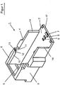
- FIG. 1 shows in a perspective view a receiving cassette 1, as it can be used to clean toilet containers.
- the receiving cassette 1 is part of an emptying and cleaning station, wherein the receiving cassette 1 is integrated in the emptying and cleaning station and mounted horizontally movable.
- the toilet bowls are hereby equipped with a first inside flap, which must be opened manually beforehand by means of a rotary knob.
- a second outer flap is displaceably mounted and is detected by a centering device within the emptying and cleaning station insofar as the cleaning element can be positioned directly above the cleaning opening of the toilet container.
- the height of the centering device is readjusted via a front wedge-shaped pressure surface and made a lateral displacement via a guide, so that the centering device comes to rest directly on the second outer flap and this shifts the further insertion of the toilet container to the side to open the cleaning opening so that the cleaning element can dip.
- the receiving cassette 1 consists of a bottom element 2 with side walls 3,4 and a rear wall 5.
- the receiving cassette 1 is designed largely open, so that a toilet container can be inserted.
- the rear portion of the receiving cassette 1 is closed by a cover, which is not shown in this view.
- On the cover a hook is pivotally mounted and allows to limit the insertion depth of the toilet container with a hook end.
- the rear wall 5 extends only over part of the overall height of the receiving cassette 1 and the side walls 3, 4 are set back relative to a front edge 17.
- the male toilet bowls can have different heights, widths and depths. To ensure that the cleaning element can be lowered directly into the cleaning opening of such a toilet container, a positioning in a certain way is required.
- the positioning within the receiving cassette 1 takes place here in the illustrated embodiment by the bottom elevations 7, 8, 9, which allow a different position of the toilet container in the depth.
- a mechanical positioning aid is provided by a partially circumferential rim 10 which extends above the side wall 3,4 and the rear wall 5 and the recessed side walls 3,4 to detect the height and width of the toilet container.
- the peripheral edge 10 and the side walls 3,4 are provided to the open front of the receiving cassette 1 out with stop surfaces 11, 12, 13, in addition, the side walls 3, 4 each have a stop surface 14. Depending on the height or width of the toilet container this can thus be inserted approximately to the rear wall, for example, if the height is below the peripheral edge 10.
- the toilet container can be inserted to the stop surface 12.
- the toilet container has an even higher volume, so that a slot only up to the stop surface 11 is possible.
- the toilet container which also have a special height, there is only the possibility to introduce them to the stop surface 13 in the receiving cassette 1.
- For toilet containers which also have a special width it is possible to introduce them to the stop surface 14 in the receiving cassette 1.
- FIG. 2 shows in a rear view of the FIG. 1 known receiving cassette 1.
- the receiving cassette 1 with a bottom element 2 and the two side walls 3, 4 has in the rear region on a rear wall 5, which extends only over part of the total height of the receiving cassette 1.
- a peripheral edge 6 is formed, which allows a supply of toilet containers of different heights to a designated depth. From this view, a stop element 15 is still visible, so that some toilet containers can not be fully inserted to the rear wall 5, but only up to the stop element 15.
- a cover 19 is further attached, which has a recess 27 and has a hook 18.
- the hook 18 is pivotally mounted on the cover 19 via a bearing element 28. When inserting the toilet container, the hook 18 is raised from a vertical position to a horizontal position, so that the toilet container can be inserted maximally to the hook end. This measure also serves to position the toilet container within the receiving cassette 1.
- FIG. 3 shows a schematic view of an emptying and cleaning station 20 with the recording cassette 1 described and a cleaning element 21.
- the emptying and cleaning station 20 is equipped with a housing 22 in which a receiving device 23 in the emptying and cleaning station 20 installed in the lower area is, and is provided at the positions 25, 26 with a pivoting mechanism to allow a pivoting movement of the receiving cassette 1.
- the feces are fed to the suction and Spühlrohr during the suction-Spühlvorgangs.
- a cleaning element 21 is connected to a lifting device 24, so that the cleaning element 21 can be introduced into an existing cleaning opening of the toilet container by a downward movement.
- the cleaning element 21 is rotatably mounted, so that all corners and angles of the toilet container in the cleaning and rinsing process can be cleaned.
- the cleaning element consists of an elastically flexible and / or deformable suction and flushing pipe.
- a double-walled tube with flexible hose connections and screw connections is used to reach all corner areas of the toilet container by means of the suction and flushing pipe.
- FIG. 4 shows in three partial views schematically a centering device 30 which is mounted on the receiving cassette 1.
- a toilet container 31 with a sliding door 32 can be inserted through the front receiving opening of the receiving cassette 1, wherein the centering unit 30 with a wedge-shaped pressure surface 33 can first make a height compensation according to the height of the toilet container 31 relative to the centering device 30.
- the pressure surface 33 slides over the front edge of the toilet container 31 and raises the centering device 30 at.
- the centering device 30 performs a lateral movement, so that the centering device 30 can not only position itself in height, but also allows a side shift, so far due to component tolerances in the introduction of the toilet container 31, the slide door 32nd not aligned with the centering device 30.
- the centering device 30 has the ability to make a leveling in height by the wedge-shaped pressure surface 33, which is withdrawn by means of a tension element 34 after removal of the toilet container 31 back to the original starting position. Via a guide 35, the centering device 30 is displaced laterally, so that alignment of the centering device 30 can be carried out on the cleaning opening of the inserted toilet container.
- the centering device 30 is held by two vertical and horizontal guide rods 38, 39 slidably. After the positioning of the toilet container 31 is done, which can be done from the FIG. 3 known cleaning element 21 through a hole 37 in the toilet tank 31 dive to start the cleaning process.
Landscapes
- Engineering & Computer Science (AREA)
- Mechanical Engineering (AREA)
- Health & Medical Sciences (AREA)
- Epidemiology (AREA)
- General Health & Medical Sciences (AREA)
- Public Health (AREA)
- Sanitary Device For Flush Toilet (AREA)
- Cleaning In General (AREA)
- Detergent Compositions (AREA)
- Drying Of Solid Materials (AREA)
Priority Applications (2)
| Application Number | Priority Date | Filing Date | Title |
|---|---|---|---|
| PL14001079T PL2799157T3 (pl) | 2013-04-30 | 2014-03-24 | Stacja opróżniania i oczyszczania z kasetą odbioru |
| HRP20200177TT HRP20200177T1 (hr) | 2013-04-30 | 2020-02-03 | Stanica za odvod i čišćenje s prijemnim spremnikom |
Applications Claiming Priority (1)
| Application Number | Priority Date | Filing Date | Title |
|---|---|---|---|
| DE102013007408.8A DE102013007408C5 (de) | 2013-04-30 | 2013-04-30 | Entleer- und Reinigungsstation mit Aufnahmekassette |
Publications (2)
| Publication Number | Publication Date |
|---|---|
| EP2799157A1 EP2799157A1 (de) | 2014-11-05 |
| EP2799157B1 true EP2799157B1 (de) | 2019-11-06 |
Family
ID=50396835
Family Applications (1)
| Application Number | Title | Priority Date | Filing Date |
|---|---|---|---|
| EP14001079.4A Active EP2799157B1 (de) | 2013-04-30 | 2014-03-24 | Entleer- und Reinigungsstation mit Aufnahmekassette |
Country Status (6)
| Country | Link |
|---|---|
| EP (1) | EP2799157B1 (da) |
| DE (1) | DE102013007408C5 (da) |
| DK (1) | DK2799157T3 (da) |
| ES (1) | ES2768259T3 (da) |
| HR (1) | HRP20200177T1 (da) |
| PL (1) | PL2799157T3 (da) |
Families Citing this family (2)
| Publication number | Priority date | Publication date | Assignee | Title |
|---|---|---|---|---|
| DE102017007791A1 (de) | 2017-08-18 | 2019-02-21 | Ralf Winkelmann | Entleerstation mit einem Reinigungselement für einen Toilettenbehälter und Verfahren zum Entleeren eines Toilettenbehälters mit einer Reinigungsöffnung |
| IT201800002444A1 (it) * | 2018-02-06 | 2019-08-06 | Loris Mosconi | Apparato di svuotamento e lavaggio di un serbatoio di accumulo di acque reflue. |
Family Cites Families (19)
| Publication number | Priority date | Publication date | Assignee | Title |
|---|---|---|---|---|
| US2230436A (en) * | 1938-03-14 | 1941-02-04 | Michael J Roche | Cleansing device |
| US2240364A (en) | 1939-01-20 | 1941-04-29 | Portland Company | Method of treating the interiors of containers |
| DE921689C (de) | 1951-01-11 | 1954-12-23 | Braunschweigische Maschb Ansta | Vorrichtung und Verfahren zum selbsttaetigen Reinigen von Behaeltern, z. B. von Metallfaessern |
| GB1036612A (en) * | 1962-02-22 | 1966-07-20 | Dent & Hellyer | Improvements in apparatus for washing bed-pans, urine bottles and the like excreta-receiving utensils |
| US4670061A (en) * | 1984-08-31 | 1987-06-02 | Sic Ag | Process for improving the automatic emptying and cleaning of hygienic vessels under optimum infeed of rinsing water at minimal water usage and arrangement for implementing the process |
| DE3833307A1 (de) * | 1988-09-30 | 1990-04-12 | Linde Ag | Verfahren und vorrichtung zum reinigen von flaschen |
| DE3920906A1 (de) | 1989-06-26 | 1991-01-10 | Henkel Kgaa | Fassentleerungsanlage |
| DE9218509U1 (de) * | 1992-03-17 | 1994-07-07 | Khs Maschinen- Und Anlagenbau Ag, 47057 Duisburg | Vorrichtung zum Behandeln von KEG, insbesondere zum Füllen von KEG |
| DE19924528A1 (de) * | 1999-05-28 | 2000-11-30 | Buehler Ag | Vorrichtung zur Reinigung von Keimhorden |
| DE10008982A1 (de) * | 2000-02-25 | 2001-09-13 | Johann Maier | Vorrichtung zum Reinigen von Behältern |
| DE20308586U1 (de) * | 2003-06-02 | 2003-11-13 | Schell, Herwig, 91315 Höchstadt | Automatische Entleerstation für Reisetoiletten |
| FR2873600B1 (fr) * | 2004-07-29 | 2006-10-13 | Pronet Soc Par Actions Simplif | Installation de lavage de conteneurs. |
| US20090095322A1 (en) * | 2005-05-13 | 2009-04-16 | Yoshitaka Wakao | Container cleaning device, container cleaning method, and tank |
| DE202007015871U1 (de) * | 2007-11-12 | 2008-03-13 | Malek Brautech Gmbh | Behandlungsvorrichtung für Behälter |
| ITMI20090399A1 (it) * | 2009-03-16 | 2010-09-17 | Gianfranco Bossio | Macchina per lo svuotamento, per il lavaggio automatico di cassette wc utilizzate in autocaravan, camper e simili. |
| DE102010005130B4 (de) * | 2010-01-19 | 2014-02-27 | Ralf Tebartz | Reinigungsgerät und Verfahren zur Reinigung von Toiletten für Campingfahrzeuge |
| DE202010012473U1 (de) * | 2010-09-10 | 2010-12-30 | Feistmantl Cleaning Systems Gmbh | Behälterreinigungssystem |
| NL2005578C2 (en) * | 2010-10-26 | 2012-04-27 | Paul Mathieu Antoon Janssen | An apparatus for emptying a portable waste holding tank. |
| DK2755695T3 (da) * | 2011-09-14 | 2017-07-31 | Meiko Maschinenbau Gmbh & Co | Cleaning and disinfecting apparatus for treating containers for human excretions |
-
2013
- 2013-04-30 DE DE102013007408.8A patent/DE102013007408C5/de active Active
-
2014
- 2014-03-24 EP EP14001079.4A patent/EP2799157B1/de active Active
- 2014-03-24 DK DK14001079.4T patent/DK2799157T3/da active
- 2014-03-24 PL PL14001079T patent/PL2799157T3/pl unknown
- 2014-03-24 ES ES14001079T patent/ES2768259T3/es active Active
-
2020
- 2020-02-03 HR HRP20200177TT patent/HRP20200177T1/hr unknown
Non-Patent Citations (1)
| Title |
|---|
| None * |
Also Published As
| Publication number | Publication date |
|---|---|
| HRP20200177T1 (hr) | 2020-05-01 |
| DE102013007408B4 (de) | 2015-03-26 |
| DE102013007408C5 (de) | 2019-11-21 |
| DK2799157T3 (da) | 2020-02-17 |
| EP2799157A1 (de) | 2014-11-05 |
| DE102013007408A1 (de) | 2014-10-30 |
| ES2768259T3 (es) | 2020-06-22 |
| PL2799157T3 (pl) | 2020-06-01 |
Similar Documents
| Publication | Publication Date | Title |
|---|---|---|
| DE102007060698B4 (de) | Selbstreinigende Toilette | |
| EP2226438B1 (de) | Betätigungsvorrichtung für einen Spülkasten und ein Spülkasten mit einer solchen Betätigungsvorrichtung sowie ein Verfahren für den Unterhalt eines solchen Spülkastens | |
| EP2842811B1 (de) | Verfahren zur Spülung einer Toilette eines Fahrzeugs und Toilette | |
| EP0280130A1 (de) | Sanitärzelle für öffentliche Zwecke | |
| DE102010005130B4 (de) | Reinigungsgerät und Verfahren zur Reinigung von Toiletten für Campingfahrzeuge | |
| EP2799157B1 (de) | Entleer- und Reinigungsstation mit Aufnahmekassette | |
| DE69432118T2 (de) | Vorrichtung zum automatischen reinigen und vorbereiten auf wiederverwendung von toiletten | |
| EP2613893B1 (de) | Behälterreinigungssystem und behälterreinigungsverfahren | |
| EP2770129A2 (de) | Entsorgungsstation für die Entsorgung von Toiletten-Kassetten von Reisemobilen, Wohnwägen und dergleichen | |
| DE102013110112B4 (de) | Reinigungsvorrichtung für kontaminierte Gegenstände und Verfahren hierzu | |
| DE10032439C1 (de) | Verfahren und Vorrichtung zum Reinigen eines Toilettenbeckens | |
| EP2425064B1 (de) | Siphon und möbel | |
| DE102015113950A1 (de) | Entsorgungsvorrichtung und -verfahren für die sanitären Einrichtungen eines Straßenfahrzeugs | |
| EP0404170B1 (de) | Vorrichtung zum Absaugen von Flüssigkeiten | |
| WO2006102871A1 (de) | Abfallbeseitigung in wohnmobilen oder dgl. | |
| DE3605446C2 (de) | Toiletteneinrichtung | |
| EP3031751A1 (de) | Spritzschutz für einen abfallbehälter, sowie einen abfallbehälter mit einem derartigen spritzschutz | |
| AT14829U1 (de) | Entleerungsstation für Fäkalientanks | |
| DE102022114274A1 (de) | Ausguss-Vorrichtung, Pfandautomaten-Vorrichtung mit einer solchen Ausguss-Vorrichtung sowie Verfahren für deren Betrieb | |
| DE3128075A1 (de) | "toilette, sowie verfahren zu ihrer entleerung" | |
| DE19723921A1 (de) | Verbesserungen im Aufbau einer Toilette, insbesondere für Freizeitwohnmobile | |
| EP2792426A2 (de) | Tankkesselfahrzeug mit integriertem Tankwaschkopf und Verfahren zum Entleeren des Tankkessels eines Tankkesselfahrzeuges | |
| DE3743672C1 (en) | Device for working with liquids | |
| DE2154652A1 (de) | Spuelklosett | |
| DE1926162U (de) | Fahrbarer behaelter zur voruebergehenden aufnahme von portionsweise anfallenden fluessigkeiten. |
Legal Events
| Date | Code | Title | Description |
|---|---|---|---|
| PUAI | Public reference made under article 153(3) epc to a published international application that has entered the european phase |
Free format text: ORIGINAL CODE: 0009012 |
|
| 17P | Request for examination filed |
Effective date: 20140324 |
|
| AK | Designated contracting states |
Kind code of ref document: A1 Designated state(s): AL AT BE BG CH CY CZ DE DK EE ES FI FR GB GR HR HU IE IS IT LI LT LU LV MC MK MT NL NO PL PT RO RS SE SI SK SM TR |
|
| AX | Request for extension of the european patent |
Extension state: BA ME |
|
| R17P | Request for examination filed (corrected) |
Effective date: 20150428 |
|
| RBV | Designated contracting states (corrected) |
Designated state(s): AL AT BE BG CH CY CZ DE DK EE ES FI FR GB GR HR HU IE IS IT LI LT LU LV MC MK MT NL NO PL PT RO RS SE SI SK SM TR |
|
| 17Q | First examination report despatched |
Effective date: 20160503 |
|
| STAA | Information on the status of an ep patent application or granted ep patent |
Free format text: STATUS: EXAMINATION IS IN PROGRESS |
|
| TPAC | Observations filed by third parties |
Free format text: ORIGINAL CODE: EPIDOSNTIPA |
|
| GRAP | Despatch of communication of intention to grant a patent |
Free format text: ORIGINAL CODE: EPIDOSNIGR1 |
|
| STAA | Information on the status of an ep patent application or granted ep patent |
Free format text: STATUS: GRANT OF PATENT IS INTENDED |
|
| INTG | Intention to grant announced |
Effective date: 20190613 |
|
| GRAS | Grant fee paid |
Free format text: ORIGINAL CODE: EPIDOSNIGR3 |
|
| GRAA | (expected) grant |
Free format text: ORIGINAL CODE: 0009210 |
|
| STAA | Information on the status of an ep patent application or granted ep patent |
Free format text: STATUS: THE PATENT HAS BEEN GRANTED |
|
| AK | Designated contracting states |
Kind code of ref document: B1 Designated state(s): AL AT BE BG CH CY CZ DE DK EE ES FI FR GB GR HR HU IE IS IT LI LT LU LV MC MK MT NL NO PL PT RO RS SE SI SK SM TR |
|
| REG | Reference to a national code |
Ref country code: GB Ref legal event code: FG4D Free format text: NOT ENGLISH |
|
| REG | Reference to a national code |
Ref country code: AT Ref legal event code: REF Ref document number: 1198056 Country of ref document: AT Kind code of ref document: T Effective date: 20191115 Ref country code: CH Ref legal event code: EP |
|
| REG | Reference to a national code |
Ref country code: IE Ref legal event code: FG4D Free format text: LANGUAGE OF EP DOCUMENT: GERMAN |
|
| REG | Reference to a national code |
Ref country code: DE Ref legal event code: R096 Ref document number: 502014012976 Country of ref document: DE |
|
| REG | Reference to a national code |
Ref country code: HR Ref legal event code: TUEP Ref document number: P20200177T Country of ref document: HR |
|
| REG | Reference to a national code |
Ref country code: DK Ref legal event code: T3 Effective date: 20200210 |
|
| REG | Reference to a national code |
Ref country code: SE Ref legal event code: TRGR |
|
| REG | Reference to a national code |
Ref country code: NL Ref legal event code: FP |
|
| REG | Reference to a national code |
Ref country code: LT Ref legal event code: MG4D |
|
| REG | Reference to a national code |
Ref country code: HR Ref legal event code: ODRP Ref document number: P20200177T Country of ref document: HR Payment date: 20200316 Year of fee payment: 7 |
|
| PG25 | Lapsed in a contracting state [announced via postgrant information from national office to epo] |
Ref country code: LV Free format text: LAPSE BECAUSE OF FAILURE TO SUBMIT A TRANSLATION OF THE DESCRIPTION OR TO PAY THE FEE WITHIN THE PRESCRIBED TIME-LIMIT Effective date: 20191106 Ref country code: BG Free format text: LAPSE BECAUSE OF FAILURE TO SUBMIT A TRANSLATION OF THE DESCRIPTION OR TO PAY THE FEE WITHIN THE PRESCRIBED TIME-LIMIT Effective date: 20200206 Ref country code: FI Free format text: LAPSE BECAUSE OF FAILURE TO SUBMIT A TRANSLATION OF THE DESCRIPTION OR TO PAY THE FEE WITHIN THE PRESCRIBED TIME-LIMIT Effective date: 20191106 Ref country code: GR Free format text: LAPSE BECAUSE OF FAILURE TO SUBMIT A TRANSLATION OF THE DESCRIPTION OR TO PAY THE FEE WITHIN THE PRESCRIBED TIME-LIMIT Effective date: 20200207 Ref country code: NO Free format text: LAPSE BECAUSE OF FAILURE TO SUBMIT A TRANSLATION OF THE DESCRIPTION OR TO PAY THE FEE WITHIN THE PRESCRIBED TIME-LIMIT Effective date: 20200206 Ref country code: LT Free format text: LAPSE BECAUSE OF FAILURE TO SUBMIT A TRANSLATION OF THE DESCRIPTION OR TO PAY THE FEE WITHIN THE PRESCRIBED TIME-LIMIT Effective date: 20191106 Ref country code: PT Free format text: LAPSE BECAUSE OF FAILURE TO SUBMIT A TRANSLATION OF THE DESCRIPTION OR TO PAY THE FEE WITHIN THE PRESCRIBED TIME-LIMIT Effective date: 20200306 |
|
| REG | Reference to a national code |
Ref country code: HR Ref legal event code: T1PR Ref document number: P20200177 Country of ref document: HR |
|
| PG25 | Lapsed in a contracting state [announced via postgrant information from national office to epo] |
Ref country code: IS Free format text: LAPSE BECAUSE OF FAILURE TO SUBMIT A TRANSLATION OF THE DESCRIPTION OR TO PAY THE FEE WITHIN THE PRESCRIBED TIME-LIMIT Effective date: 20200306 Ref country code: RS Free format text: LAPSE BECAUSE OF FAILURE TO SUBMIT A TRANSLATION OF THE DESCRIPTION OR TO PAY THE FEE WITHIN THE PRESCRIBED TIME-LIMIT Effective date: 20191106 |
|
| REG | Reference to a national code |
Ref country code: ES Ref legal event code: FG2A Ref document number: 2768259 Country of ref document: ES Kind code of ref document: T3 Effective date: 20200622 |
|
| PG25 | Lapsed in a contracting state [announced via postgrant information from national office to epo] |
Ref country code: AL Free format text: LAPSE BECAUSE OF FAILURE TO SUBMIT A TRANSLATION OF THE DESCRIPTION OR TO PAY THE FEE WITHIN THE PRESCRIBED TIME-LIMIT Effective date: 20191106 |
|
| PG25 | Lapsed in a contracting state [announced via postgrant information from national office to epo] |
Ref country code: RO Free format text: LAPSE BECAUSE OF FAILURE TO SUBMIT A TRANSLATION OF THE DESCRIPTION OR TO PAY THE FEE WITHIN THE PRESCRIBED TIME-LIMIT Effective date: 20191106 Ref country code: CZ Free format text: LAPSE BECAUSE OF FAILURE TO SUBMIT A TRANSLATION OF THE DESCRIPTION OR TO PAY THE FEE WITHIN THE PRESCRIBED TIME-LIMIT Effective date: 20191106 Ref country code: EE Free format text: LAPSE BECAUSE OF FAILURE TO SUBMIT A TRANSLATION OF THE DESCRIPTION OR TO PAY THE FEE WITHIN THE PRESCRIBED TIME-LIMIT Effective date: 20191106 |
|
| REG | Reference to a national code |
Ref country code: DE Ref legal event code: R097 Ref document number: 502014012976 Country of ref document: DE |
|
| PG25 | Lapsed in a contracting state [announced via postgrant information from national office to epo] |
Ref country code: SM Free format text: LAPSE BECAUSE OF FAILURE TO SUBMIT A TRANSLATION OF THE DESCRIPTION OR TO PAY THE FEE WITHIN THE PRESCRIBED TIME-LIMIT Effective date: 20191106 Ref country code: SK Free format text: LAPSE BECAUSE OF FAILURE TO SUBMIT A TRANSLATION OF THE DESCRIPTION OR TO PAY THE FEE WITHIN THE PRESCRIBED TIME-LIMIT Effective date: 20191106 |
|
| PLBE | No opposition filed within time limit |
Free format text: ORIGINAL CODE: 0009261 |
|
| STAA | Information on the status of an ep patent application or granted ep patent |
Free format text: STATUS: NO OPPOSITION FILED WITHIN TIME LIMIT |
|
| 26N | No opposition filed |
Effective date: 20200807 |
|
| PG25 | Lapsed in a contracting state [announced via postgrant information from national office to epo] |
Ref country code: MC Free format text: LAPSE BECAUSE OF FAILURE TO SUBMIT A TRANSLATION OF THE DESCRIPTION OR TO PAY THE FEE WITHIN THE PRESCRIBED TIME-LIMIT Effective date: 20191106 |
|
| PG25 | Lapsed in a contracting state [announced via postgrant information from national office to epo] |
Ref country code: SI Free format text: LAPSE BECAUSE OF FAILURE TO SUBMIT A TRANSLATION OF THE DESCRIPTION OR TO PAY THE FEE WITHIN THE PRESCRIBED TIME-LIMIT Effective date: 20191106 |
|
| PG25 | Lapsed in a contracting state [announced via postgrant information from national office to epo] |
Ref country code: LU Free format text: LAPSE BECAUSE OF NON-PAYMENT OF DUE FEES Effective date: 20200324 |
|
| PG25 | Lapsed in a contracting state [announced via postgrant information from national office to epo] |
Ref country code: IE Free format text: LAPSE BECAUSE OF NON-PAYMENT OF DUE FEES Effective date: 20200324 |
|
| REG | Reference to a national code |
Ref country code: HR Ref legal event code: ODRP Ref document number: P20200177 Country of ref document: HR Payment date: 20210317 Year of fee payment: 8 |
|
| REG | Reference to a national code |
Ref country code: HR Ref legal event code: ODRP Ref document number: P20200177 Country of ref document: HR Payment date: 20220315 Year of fee payment: 9 |
|
| PGFP | Annual fee paid to national office [announced via postgrant information from national office to epo] |
Ref country code: CH Payment date: 20220324 Year of fee payment: 9 Ref country code: AT Payment date: 20220318 Year of fee payment: 9 |
|
| PG25 | Lapsed in a contracting state [announced via postgrant information from national office to epo] |
Ref country code: TR Free format text: LAPSE BECAUSE OF FAILURE TO SUBMIT A TRANSLATION OF THE DESCRIPTION OR TO PAY THE FEE WITHIN THE PRESCRIBED TIME-LIMIT Effective date: 20191106 Ref country code: MT Free format text: LAPSE BECAUSE OF FAILURE TO SUBMIT A TRANSLATION OF THE DESCRIPTION OR TO PAY THE FEE WITHIN THE PRESCRIBED TIME-LIMIT Effective date: 20191106 Ref country code: CY Free format text: LAPSE BECAUSE OF FAILURE TO SUBMIT A TRANSLATION OF THE DESCRIPTION OR TO PAY THE FEE WITHIN THE PRESCRIBED TIME-LIMIT Effective date: 20191106 |
|
| PGFP | Annual fee paid to national office [announced via postgrant information from national office to epo] |
Ref country code: BE Payment date: 20220322 Year of fee payment: 9 |
|
| PG25 | Lapsed in a contracting state [announced via postgrant information from national office to epo] |
Ref country code: MK Free format text: LAPSE BECAUSE OF FAILURE TO SUBMIT A TRANSLATION OF THE DESCRIPTION OR TO PAY THE FEE WITHIN THE PRESCRIBED TIME-LIMIT Effective date: 20191106 |
|
| REG | Reference to a national code |
Ref country code: HR Ref legal event code: ODRP Ref document number: P20200177 Country of ref document: HR Payment date: 20230316 Year of fee payment: 10 |
|
| REG | Reference to a national code |
Ref country code: CH Ref legal event code: PL |
|
| REG | Reference to a national code |
Ref country code: AT Ref legal event code: MM01 Ref document number: 1198056 Country of ref document: AT Kind code of ref document: T Effective date: 20230324 |
|
| REG | Reference to a national code |
Ref country code: BE Ref legal event code: MM Effective date: 20230331 |
|
| PG25 | Lapsed in a contracting state [announced via postgrant information from national office to epo] |
Ref country code: LI Free format text: LAPSE BECAUSE OF NON-PAYMENT OF DUE FEES Effective date: 20230331 Ref country code: CH Free format text: LAPSE BECAUSE OF NON-PAYMENT OF DUE FEES Effective date: 20230331 Ref country code: AT Free format text: LAPSE BECAUSE OF NON-PAYMENT OF DUE FEES Effective date: 20230324 |
|
| REG | Reference to a national code |
Ref country code: DE Ref legal event code: R082 Ref document number: 502014012976 Country of ref document: DE Representative=s name: SEYER & NOBBE PATENTANWAELTE PARTNERSCHAFTSGES, DE |
|
| PG25 | Lapsed in a contracting state [announced via postgrant information from national office to epo] |
Ref country code: BE Free format text: LAPSE BECAUSE OF NON-PAYMENT OF DUE FEES Effective date: 20230331 |
|
| REG | Reference to a national code |
Ref country code: HR Ref legal event code: ODRP Ref document number: P20200177 Country of ref document: HR Payment date: 20240313 Year of fee payment: 11 |
|
| PGFP | Annual fee paid to national office [announced via postgrant information from national office to epo] |
Ref country code: NL Payment date: 20240320 Year of fee payment: 11 |
|
| PGFP | Annual fee paid to national office [announced via postgrant information from national office to epo] |
Ref country code: DE Payment date: 20240227 Year of fee payment: 11 Ref country code: GB Payment date: 20240322 Year of fee payment: 11 |
|
| PGFP | Annual fee paid to national office [announced via postgrant information from national office to epo] |
Ref country code: SE Payment date: 20240321 Year of fee payment: 11 Ref country code: PL Payment date: 20240228 Year of fee payment: 11 Ref country code: IT Payment date: 20240329 Year of fee payment: 11 Ref country code: HR Payment date: 20240313 Year of fee payment: 11 Ref country code: FR Payment date: 20240320 Year of fee payment: 11 Ref country code: DK Payment date: 20240321 Year of fee payment: 11 |
|
| PGFP | Annual fee paid to national office [announced via postgrant information from national office to epo] |
Ref country code: ES Payment date: 20240417 Year of fee payment: 11 |