EP2799157B1 - Draining and cleaning station with receiving cartridge - Google Patents
Draining and cleaning station with receiving cartridge Download PDFInfo
- Publication number
- EP2799157B1 EP2799157B1 EP14001079.4A EP14001079A EP2799157B1 EP 2799157 B1 EP2799157 B1 EP 2799157B1 EP 14001079 A EP14001079 A EP 14001079A EP 2799157 B1 EP2799157 B1 EP 2799157B1
- Authority
- EP
- European Patent Office
- Prior art keywords
- cleaning
- toilet
- toilet container
- suction
- container
- Prior art date
- Legal status (The legal status is an assumption and is not a legal conclusion. Google has not performed a legal analysis and makes no representation as to the accuracy of the status listed.)
- Active
Links
- 238000004140 cleaning Methods 0.000 title claims description 191
- 238000000034 method Methods 0.000 claims description 26
- 238000011010 flushing procedure Methods 0.000 claims description 22
- 230000033001 locomotion Effects 0.000 claims description 19
- 239000007788 liquid Substances 0.000 claims description 9
- 230000007246 mechanism Effects 0.000 claims description 8
- 230000006978 adaptation Effects 0.000 claims description 6
- 230000003287 optical effect Effects 0.000 claims description 6
- 238000003780 insertion Methods 0.000 claims description 5
- 230000037431 insertion Effects 0.000 claims description 5
- 230000004888 barrier function Effects 0.000 claims description 4
- 239000012459 cleaning agent Substances 0.000 claims description 3
- 238000001514 detection method Methods 0.000 claims description 3
- 238000003825 pressing Methods 0.000 claims description 3
- 239000013505 freshwater Substances 0.000 claims description 2
- 239000007921 spray Substances 0.000 claims description 2
- 239000000645 desinfectant Substances 0.000 claims 1
- 238000007373 indentation Methods 0.000 claims 1
- 230000008569 process Effects 0.000 description 17
- 210000003608 fece Anatomy 0.000 description 8
- 238000011109 contamination Methods 0.000 description 7
- 230000008901 benefit Effects 0.000 description 5
- 239000002184 metal Substances 0.000 description 4
- 230000005540 biological transmission Effects 0.000 description 3
- 238000000605 extraction Methods 0.000 description 3
- 239000000945 filler Substances 0.000 description 3
- 230000002093 peripheral effect Effects 0.000 description 3
- 239000002689 soil Substances 0.000 description 3
- OKTJSMMVPCPJKN-UHFFFAOYSA-N Carbon Chemical compound [C] OKTJSMMVPCPJKN-UHFFFAOYSA-N 0.000 description 2
- 239000000356 contaminant Substances 0.000 description 2
- 230000001419 dependent effect Effects 0.000 description 2
- 201000010099 disease Diseases 0.000 description 2
- 208000037265 diseases, disorders, signs and symptoms Diseases 0.000 description 2
- 238000006073 displacement reaction Methods 0.000 description 2
- 239000002245 particle Substances 0.000 description 2
- 230000009467 reduction Effects 0.000 description 2
- XLYOFNOQVPJJNP-UHFFFAOYSA-N water Substances O XLYOFNOQVPJJNP-UHFFFAOYSA-N 0.000 description 2
- 241000196324 Embryophyta Species 0.000 description 1
- 235000004443 Ricinus communis Nutrition 0.000 description 1
- 240000000528 Ricinus communis Species 0.000 description 1
- 244000052616 bacterial pathogen Species 0.000 description 1
- 230000008859 change Effects 0.000 description 1
- 238000000354 decomposition reaction Methods 0.000 description 1
- 238000009826 distribution Methods 0.000 description 1
- 238000005553 drilling Methods 0.000 description 1
- 230000036541 health Effects 0.000 description 1
- 239000004615 ingredient Substances 0.000 description 1
- 230000009965 odorless effect Effects 0.000 description 1
- 230000002787 reinforcement Effects 0.000 description 1
- 239000010865 sewage Substances 0.000 description 1
- 238000003860 storage Methods 0.000 description 1
- 230000001960 triggered effect Effects 0.000 description 1
- 238000011144 upstream manufacturing Methods 0.000 description 1
- 239000002699 waste material Substances 0.000 description 1
Images


Classifications
-
- B—PERFORMING OPERATIONS; TRANSPORTING
- B08—CLEANING
- B08B—CLEANING IN GENERAL; PREVENTION OF FOULING IN GENERAL
- B08B9/00—Cleaning hollow articles by methods or apparatus specially adapted thereto
- B08B9/08—Cleaning containers, e.g. tanks
- B08B9/0821—Handling or manipulating containers, e.g. moving or rotating containers in cleaning devices, conveying to or from cleaning devices
- B08B9/0826—Handling or manipulating containers, e.g. moving or rotating containers in cleaning devices, conveying to or from cleaning devices the containers being brought to the cleaning device
-
- B—PERFORMING OPERATIONS; TRANSPORTING
- B08—CLEANING
- B08B—CLEANING IN GENERAL; PREVENTION OF FOULING IN GENERAL
- B08B9/00—Cleaning hollow articles by methods or apparatus specially adapted thereto
- B08B9/08—Cleaning containers, e.g. tanks
- B08B9/093—Cleaning containers, e.g. tanks by the force of jets or sprays
- B08B9/0936—Cleaning containers, e.g. tanks by the force of jets or sprays using rotating jets
-
- B—PERFORMING OPERATIONS; TRANSPORTING
- B60—VEHICLES IN GENERAL
- B60R—VEHICLES, VEHICLE FITTINGS, OR VEHICLE PARTS, NOT OTHERWISE PROVIDED FOR
- B60R15/00—Arrangements or adaptations of sanitation devices
- B60R15/04—Toilet facilities
Definitions
- the invention relates to an emptying and cleaning station for a retractable toilet container with a receiving cassette and a receiving opening, wherein the emptying and cleaning station has at least one cleaning element which can be inserted and automatically lowered via a cleaning opening of the toilet container and a method for cleaning a toilet container.
- a toilet container as a module of a toilet facility.
- this may be a normal toilet, the contents of the toilet container via an outlet or a cleaning port is disposed of.
- the toilet container must be brought into a specific position in order to ensure a smooth emptying of the contents of the toilet container.
- the problem is that the disposal of the toilet container contents on the outlet has to be done so that the content can be collected point and accurate to the disposal site.
- this is usually not readily possible, since a continuous outflow of the toilet container contents via an outlet after the nature of the content is already not possible and thus enters a gradual contamination of the disposal area. This is to be understood as pollution both the burden of disposal parts with ingredients of the toilet dealer and an odor in the vicinity of the disposal site.
- the emptying of the toilet container is done manually so far.
- the toilet bowls are here in a drawer, which is adapted to the respective toilet container size and in turn is located directly under the toilet bowl in a motorhome.
- the toilet bowls themselves are equipped with a handle, a vent valve and a filler neck, with which the feces via toilet bowl into the toilet container.
- the toilet bowls can have a swiveling discharge nozzle and, depending on the model, castors for easier transport.
- the filler neck and emptying but can collapse and form a cleaning hole.
- the toilet containers in this case have an inner first flap for opening the cleaning opening, which can be opened, for example by means of a knob.
- some toilet bowls have a second outer closure member with a slide mechanism which allows lateral displacement of the closure member.
- the toilet containers For emptying the toilet containers are sometimes provided by campsites emptying places of camping facilities. For these emptying places, the toilet containers must be transported by hand and emptied. The emptying takes place via the cleaning opening, for which purpose a screw cap closure, if present, must first be removed, or the inner flap is opened by the rotary knob. The toilet bowl must then be held by hand over the drain point and at the same time the vent valve pressed so that the contents (the faeces) can escape.
- a cleaning station is used, in which a metal drum can be inserted and an opening of the metal barrel a rigid suction lance is introduced with spray nozzle openings.
- the metal drum itself is fixed at an angle of about 45 ° and can be rotated around the diagonal axis over 360 °. For this reason, a rigid suction lance is used in this device.
- the DE 10 2010 005 130 A1 discloses a cleaning device and a method for cleaning toilets for recreational vehicles with an embodiment of the cleaning element.
- the supply of the cleaning element for different toilet containers has not yet been solved satisfactorily.
- the object of the invention is therefore to show an adaptability to accommodate the different sized toilet containers of the camping vehicles in an emptying and cleaning station to perform a fully automatic cleaning.
- the object of the invention is to provide the receptacle cassette for accommodating different sizes of toilet container, wherein the cleaning element can be positioned above the cleaning opening by means of positioning means and a centering device, the centering device adapting to the height of the toilet container via a wedge-shaped contact surface a guide is a lateral positioning of the cleaning element relative to the cleaning opening to move the closure of the toilet container simultaneously via a slide in an open position.
- a recording cassette is integrated, which can be used to hold different sized toilet containers and offers the possibility to position the toilet container with its cleaning opening approximately below the cleaning element.
- the toilet container is inserted into the receiving cassette of the emptying and cleaning station insofar that the cleaning opening comes to rest under the cleaning element.
- the positioning means here the handling is much easier and non-professionals can perform such a cleaning, especially if the cleaning should be initiated by the campers themselves.
- each owner of a camping car can transport the toilet container to the emptying and cleaning station and into the recording cassette of Insert emptying and cleaning station. against payment of a small fee can then run the fully automatic cleaning process, so that after completion of the cleaning process, the toilet container from the receiving cassette of the emptying and cleaning station can be removed to place him back in the caravan.
- this has at least one receiving opening, which is preferably located on an end face, or may extend from the end face up to the upper portion partially.
- a receiving cassette is used, which has two side walls next to a bottom and a rear wall and a cover in the rear area, so that the front area and the upper part are partially open to insert the toilet container without difficulty in the receiving cassette and Align the cleaning element over the cleaning opening of the toilet container.
- an inner first flap is previously opened for this purpose via a rotary knob, so that a cleaning element can be lowered into the cleaning opening.
- a second closure element provided on the outside can be displaced laterally by the centering device in order to open the cleaning opening completely.
- This closure element is automatically moved to an open position upon insertion of the toilet container in order to start the automatic cleaning procedure. So that the second closure element can be opened and the cleaning opening of the toilet container comes to rest under a cleaning element, the emptying and cleaning station has a centering device, which via a wedge-shaped pressure surface adaptation to the height of the toilet container and a guide a lateral positioning of the cleaning element opposite the cleaning opening allows.
- the wedge-shaped pressure surface is used primarily to make an adjustment to the height of the toilet container, while the Centering over the guide is additionally adjustable laterally to align the cleaning element with respect to the cleaning opening.
- the cleaning process can be started by pressing a start button, wherein in a first step, the cleaning element is automatically lowered into the cleaning opening of the toilet container.
- the positioning means and the centering device are provided.
- the centering device the cleaning opening of the toilet container can be arranged directly under the cleaning element, wherein the receiving cassette is equipped with locking means to take into account different lengths and heights of the toilet container within the receiving cassette.
- a pivoting hook can be attached to an upper rear cover, which is pushed during insertion of the toilet container from a vertical position to a horizontal position, at the same time the hook end engages in a recessed grip of the toilet container and determines the depth position. Then the cleaning process is started and the cleaning of the toilet container completed. After completion of the cleaning process, the cleaning element is pulled out of the interior of the toilet container, so that the toilet container from the receiving cassette of the emptying and cleaning station can be removed again.
- the supply of a toilet container in the receiving cassette has in particular the advantage that a direct contact of the environment with the contents of the toilet container during the cleaning process can be excluded so that pollution of the environment and a transmission of diseases can also be largely excluded. Further contributes to the automatic cleaning process and with the automatic Absenkbarkeit and liftability of the cleaning element to do so to minimize the level of pollution and the risk of transmission of germs around the supply center. In addition, by means of the cleaning element and the receiving cassette itself can be cleaned when the toilet container was removed, so that contamination of the toilet container outside can also be excluded. This ensures that an optimal cleaning of subsequently used toilet containers takes place without any contamination on the outside.
- the receiving cassette is in this case equipped with a receiving opening which is provided for receiving the toilet container in order to introduce the toilet container in the emptying and cleaning station.
- a receiving opening which is provided for receiving the toilet container in order to introduce the toilet container in the emptying and cleaning station.
- This provides easy access to the emptying and cleaning station, whereby the storage of the toilet container and removal from the receiving cassette can be done in a few steps.
- the positioning means consist of optical, mechanical and / or electromechanical elements.
- the optical elements may for example consist of light barriers, reflection light barriers or proximity switches, which can scan the outer housing surface of the toilet container and thus determine their size.
- Mechanical elements may in this case for example consist of guide rails and / or stops, against which the toilet container comes to rest, while as electromechanical elements, for example, contact switches can be used, which trigger at a corresponding size and length of the toilet container and thus a determination of the size of the toilet container enable.
- the cleaning element itself is characterized by its own drive, which can perform a horizontal and / or vertical movement, in particular, the cleaning element can be configured elastically flexible and / or deformable, so as to reach all corners of the toilet container.
- the cleaning element By means of the cleaning element, the contents of the toilet container, that is, the fecal matter, first completely sucked and then sprayed a cleaning liquid into the toilet container, which is also sucked off, so that a flushing of the entire toilet container takes place.
- the flushing of the toilet tank is usually done with fresh water during the suction process.
- the addition of a defined amount of clarifying liquid can be carried out, which is provided for the decomposition of the fecal matter and the odor reduction.
- the recording cassette and the emptying and cleaning station form the basis for cleaning the toilet bowls of various designs.
- various common models of toilet containers are known on the market, which are sometimes equipped with drawers or used individually.
- the individual drawers are hereby interchangeable, so that discontinued models and new models can be considered in order to adjust to the current market change, the toilet containers are either taken out of the drawers and inserted into the receiving cassette, or alternatively the toilet bowl together the drawer can be inserted into the receiving cassette.
- the cleaning element used here can be configured as a suction and flushing pipe, which performs a rotating movement.
- the rotating movement is triggered by an existing drive and is within of the toilet container therefore required so that within the toilet container a uniform cleaning of the surface, including all corner areas, can be done without areas of the toilet container are spared by the cleaning. It is also ensured by such a rotation that are dissolved on the cleaning element adhering contaminants.
- a pendulum mechanism facilitates the movement of the suction and flushing pipe. Due to the pendulum mechanism, the cassette in the cassette holder is set in motion and thereby all dirt particles are fed to the suction and Spühlrohr. Thus, the adhesion of contaminants to the cleaning element is prevented or impeded by the rotational movement of the suction and flushing pipe, whereby a continuous and uniform cleaning of the inside of the toilet container is ensured.
- the suction and flushing pipe is made elastic, flexible and / or deformable for better mobility of the cleaning element.
- optimal cleaning of the interior whereby the movement of the toilet container is easily carried out by the special design of the suction and flushing tube and damage to the container can be excluded.
- the cleaning element is designed as a suction and flushing pipe such that a double-walled pipe is present so that a suction and rinsing process can take place simultaneously.
- a suction and flushing pipe On the suction and flushing pipe are outside the receiving device, two flexible hoses, one for the supply of cleaning agents and rinsing liquid for flushing the toilet container and a provided for the extraction of the toilet container contents.
- the connectable to the cleaning element hoses with screw in this case allow an individual connection with locally available supply and disposal facilities, which can optionally be done by adapter adaptation to existing pipe systems. For example, if such cleaning equipment to be installed in countries with different supply and disposal connections.
- the inner tube of the cleaning element has an opening for suction of the toilet container contents.
- the inner tube has a sufficient cross section through which the components of the toilet container contents are sucked into the inner tube. It is possible that a flushing of the toilet container can be done simultaneously or with a time delay to the suction, so first there is a suction of the contents of the toilet container with a subsequent flushing or a temporally upstream flushing followed by suction and a simultaneous flushing and suction could take place.
- the suction of the liquids from the toilet container is carried out using a suction pump.
- This has over pressure pumps the advantage that no pressure in the toilet tank must be generated by a previous liquid entry to cause leakage of the components located in the toilet container, which pollution of the environment of the disposal station is prevented due to possibly smaller leaks of the toilet container or the filler neck.
- the suction pump is according to the invention equipped as an electric pump that emits its exhaust air via an activated carbon filter odorless to the environment.
- the lowering, the lifting and / or the rotation of the cleaning element via an electric motor, a hydraulic drive and / or via water pressure.
- the receiving cassette can be pivotally mounted in the emptying and cleaning station, wherein the pivoting movement is performed by an electric motor, a hydraulic drive or a different water pressure.
- the cleaning process can be performed automatically and / or manually controllable, with an adjustment to different container sizes can be done to prevent contamination of the disposal stations by the toilet container contents. In order to fulfill this condition, it is necessary to ensure automatic cleaning of the toilet bowl.
- the lowering, lifting and rotation of the cleaning element is done automatically and / or manually, so that a cleaning is not dependent on the automatic of the drive alone.
- an individual depth adjustment of the cleaning element with respect to the cleaning opening of the toilet container can be made.
- the emptying and cleaning station is connected to a sewage pit or to a tank via a piping or hose system, so that the user of such a system otherwise does not have to do any work. Due to the automatic and hygienic cleaning process without any special physical effort thus effectively cleaning the toilet containers for mobile toilets.
- the invention has the object to show an optimized method for cleaning toilet containers for camping vehicles, which is particularly adapted to the use of different sizes of toilet containers.
- a method for cleaning toilet containers wherein the automatic introduction of an elastically flexible and / or deformable suction and flushing pipe takes place as a cleaning element in the toilet container and by a drive a horizontal and / or vertical movement the suction and flushing pipe is performed and a flushing and suction of the contents of the toilet container, which is characterized by an automatic detection of the size of the toilet container, wherein the cleaning element is positioned by positioning means and a centering device above the cleaning opening, wherein the centering device via a wedge-shaped pressure surface makes an adjustment to the height of the toilet container and via a guide lateral positioning of the cleaning element relative to the cleaning opening is made to move the closure of the toilet container simultaneously via a slide in an open position.
- the process steps are aligned in their sequence to allow a pollution-free cleaning of the toilet container for recreational vehicles, with an exact positioning of the cleaning opening is provided under the cleaning element for different sized toilet containers by a centering device.
- This automatic positioning leads to the significant advantage that after the supply of the toilet container via a movement device, a suction and flushing pipe can be lowered into the cleaning opening. Once the sink has been lowered into the toilet bowl, a flush and suction of the toilet bowl can be initiated.
- the rinsing and suction can be carried out simultaneously or in two successive steps, wherein the rinsing and suction via an external, connected to the emptying and cleaning station pump unit is initiated.
- the particular advantage of the present invention is that different sizes of toilet containers can be emptied by means of an emptying and cleaning station.
- An automatic adaptation system using positioning means ensures that the toilet bowl comes to lie directly below the cleaning element with its cleaning opening, so that the cleaning element needs to be lowered only through the cleaning opening in the cleaning container before the cleaning process starts.
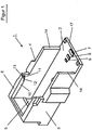
- FIG. 1 shows in a perspective view a receiving cassette 1, as it can be used to clean toilet containers.
- the receiving cassette 1 is part of an emptying and cleaning station, wherein the receiving cassette 1 is integrated in the emptying and cleaning station and mounted horizontally movable.
- the toilet bowls are hereby equipped with a first inside flap, which must be opened manually beforehand by means of a rotary knob.
- a second outer flap is displaceably mounted and is detected by a centering device within the emptying and cleaning station insofar as the cleaning element can be positioned directly above the cleaning opening of the toilet container.
- the height of the centering device is readjusted via a front wedge-shaped pressure surface and made a lateral displacement via a guide, so that the centering device comes to rest directly on the second outer flap and this shifts the further insertion of the toilet container to the side to open the cleaning opening so that the cleaning element can dip.
- the receiving cassette 1 consists of a bottom element 2 with side walls 3,4 and a rear wall 5.
- the receiving cassette 1 is designed largely open, so that a toilet container can be inserted.
- the rear portion of the receiving cassette 1 is closed by a cover, which is not shown in this view.
- On the cover a hook is pivotally mounted and allows to limit the insertion depth of the toilet container with a hook end.
- the rear wall 5 extends only over part of the overall height of the receiving cassette 1 and the side walls 3, 4 are set back relative to a front edge 17.
- the male toilet bowls can have different heights, widths and depths. To ensure that the cleaning element can be lowered directly into the cleaning opening of such a toilet container, a positioning in a certain way is required.
- the positioning within the receiving cassette 1 takes place here in the illustrated embodiment by the bottom elevations 7, 8, 9, which allow a different position of the toilet container in the depth.
- a mechanical positioning aid is provided by a partially circumferential rim 10 which extends above the side wall 3,4 and the rear wall 5 and the recessed side walls 3,4 to detect the height and width of the toilet container.
- the peripheral edge 10 and the side walls 3,4 are provided to the open front of the receiving cassette 1 out with stop surfaces 11, 12, 13, in addition, the side walls 3, 4 each have a stop surface 14. Depending on the height or width of the toilet container this can thus be inserted approximately to the rear wall, for example, if the height is below the peripheral edge 10.
- the toilet container can be inserted to the stop surface 12.
- the toilet container has an even higher volume, so that a slot only up to the stop surface 11 is possible.
- the toilet container which also have a special height, there is only the possibility to introduce them to the stop surface 13 in the receiving cassette 1.
- For toilet containers which also have a special width it is possible to introduce them to the stop surface 14 in the receiving cassette 1.
- FIG. 2 shows in a rear view of the FIG. 1 known receiving cassette 1.
- the receiving cassette 1 with a bottom element 2 and the two side walls 3, 4 has in the rear region on a rear wall 5, which extends only over part of the total height of the receiving cassette 1.
- a peripheral edge 6 is formed, which allows a supply of toilet containers of different heights to a designated depth. From this view, a stop element 15 is still visible, so that some toilet containers can not be fully inserted to the rear wall 5, but only up to the stop element 15.
- a cover 19 is further attached, which has a recess 27 and has a hook 18.
- the hook 18 is pivotally mounted on the cover 19 via a bearing element 28. When inserting the toilet container, the hook 18 is raised from a vertical position to a horizontal position, so that the toilet container can be inserted maximally to the hook end. This measure also serves to position the toilet container within the receiving cassette 1.
- FIG. 3 shows a schematic view of an emptying and cleaning station 20 with the recording cassette 1 described and a cleaning element 21.
- the emptying and cleaning station 20 is equipped with a housing 22 in which a receiving device 23 in the emptying and cleaning station 20 installed in the lower area is, and is provided at the positions 25, 26 with a pivoting mechanism to allow a pivoting movement of the receiving cassette 1.
- the feces are fed to the suction and Spühlrohr during the suction-Spühlvorgangs.
- a cleaning element 21 is connected to a lifting device 24, so that the cleaning element 21 can be introduced into an existing cleaning opening of the toilet container by a downward movement.
- the cleaning element 21 is rotatably mounted, so that all corners and angles of the toilet container in the cleaning and rinsing process can be cleaned.
- the cleaning element consists of an elastically flexible and / or deformable suction and flushing pipe.
- a double-walled tube with flexible hose connections and screw connections is used to reach all corner areas of the toilet container by means of the suction and flushing pipe.
- FIG. 4 shows in three partial views schematically a centering device 30 which is mounted on the receiving cassette 1.
- a toilet container 31 with a sliding door 32 can be inserted through the front receiving opening of the receiving cassette 1, wherein the centering unit 30 with a wedge-shaped pressure surface 33 can first make a height compensation according to the height of the toilet container 31 relative to the centering device 30.
- the pressure surface 33 slides over the front edge of the toilet container 31 and raises the centering device 30 at.
- the centering device 30 performs a lateral movement, so that the centering device 30 can not only position itself in height, but also allows a side shift, so far due to component tolerances in the introduction of the toilet container 31, the slide door 32nd not aligned with the centering device 30.
- the centering device 30 has the ability to make a leveling in height by the wedge-shaped pressure surface 33, which is withdrawn by means of a tension element 34 after removal of the toilet container 31 back to the original starting position. Via a guide 35, the centering device 30 is displaced laterally, so that alignment of the centering device 30 can be carried out on the cleaning opening of the inserted toilet container.
- the centering device 30 is held by two vertical and horizontal guide rods 38, 39 slidably. After the positioning of the toilet container 31 is done, which can be done from the FIG. 3 known cleaning element 21 through a hole 37 in the toilet tank 31 dive to start the cleaning process.
Description
Die Erfindung betrifft eine Entleer- und Reinigungsstation für einen einschiebbaren Toilettenbehälter mit einer Aufnahmekassette und einer Aufnahmeöffnung, wobei die Entleer- und Reinigungsstation zumindest ein Reinigungselement aufweist, welches über eine Reinigungsöffnung des Toilettenbehälters einführbar und automatisch absenk- und anhebbar ist, sowie ein Verfahren zur Reinigung eines Toilettenbehälters.The invention relates to an emptying and cleaning station for a retractable toilet container with a receiving cassette and a receiving opening, wherein the emptying and cleaning station has at least one cleaning element which can be inserted and automatically lowered via a cleaning opening of the toilet container and a method for cleaning a toilet container.
Die Reinigung von Toilettenbehältem, wie sie insbesondere bei Campingfahrzeugen vorzufinden sind, erfolgt durch die Entnahme eines Toilettenbehälters als Modul einer Toilettenanlage. An einer Entleerungsstation, hierbei kann es sich um eine normale Toilettenanlage handeln, wird der Inhalt des Toilettenbehälters über einen Auslassstutzen oder eine Reinigungsöffnung entsorgt. Dafür muss der Toilettenbehälter in eine bestimmte Position gebracht werden, um eine leichtgängige Entleerung des Inhalts des Toilettenbehälters gewährleisten zu können. Problematisch ist jedoch, dass die Entsorgung des Toilettenbehälterinhalts über den Auslassstutzen so zu erfolgen hat, dass der Inhalt punkt- und zielgenau an der Entsorgungsstelle aufgefangen werden kann. Dies ist jedoch in der Regel nicht ohne Weiteres möglich, da ein kontinuierlicher Abfluss des Toilettenbehälterinhalts über einen Auslassstutzen nach der Art des Inhaltes schon nicht möglich ist und somit eine sukzessive Verschmutzung des Entsorgungsbereichs eintritt. Dabei ist unter Verschmutzung sowohl die Belastung der Entsorgungsteile mit Inhaltsstoffen des Toilettenhändlers als auch eine Geruchsbelästigung in der näheren Umgebung der Entsorgungsstelle zu verstehen.The cleaning of Toilettenbehältem, as they are especially found in recreational vehicles, by removing a toilet container as a module of a toilet facility. At a drainage station, this may be a normal toilet, the contents of the toilet container via an outlet or a cleaning port is disposed of. For this, the toilet container must be brought into a specific position in order to ensure a smooth emptying of the contents of the toilet container. The problem, however, is that the disposal of the toilet container contents on the outlet has to be done so that the content can be collected point and accurate to the disposal site. However, this is usually not readily possible, since a continuous outflow of the toilet container contents via an outlet after the nature of the content is already not possible and thus enters a gradual contamination of the disposal area. This is to be understood as pollution both the burden of disposal parts with ingredients of the toilet dealer and an odor in the vicinity of the disposal site.
Die Entleerung der Toilettenbehälter erfolgt bisher manuell. Hierzu werden die Toilettenbehälter der Toilettenanlage von Wohnmobilen, Caravans oder Autoanlagen von Hand entnommen. Die Toilettenbehälter befinden sich hierbei in einem Schubkasten, der auf die jeweiligen Toilettenbehältergröße abgestimmt ist und sich wiederum direkt unter der Toilettenschüssel bei einem Wohnmobil befindet. Die Toilettenbehälter selbst sind mit einem Handgriff, einem Entlüftungsventil und einem Einfüllstützen ausgestattet, mit dem die Fäkalien via Toilettenschüssel in die Toilettenbehälter gelangen. Ferner können die Toilettenbehälter über einen schwenkbaren Entleerungsstutzen und abhängig vom Modell über Laufrollen zu einem leichteren Transport verfügen. Der Einfüllstutzen und Entleerungsstutzen können aber zusammenfallen und eine Reinigungsöffnung bilden. Die Toilettenbehälter weisen hierbei eine innenliegende erste Klappe zum Öffnen der Reinigungsöffnung auf, welche beispielsweise mithilfe eines Drehknopfes geöffnet werden kann. Darüber hinaus verfügen einige Toilettenbehälter über ein zweites äußeres Verschlusselement mit einem Schiebemechanismus, welcher eine seitliche Verschiebung des Verschlusselementes ermöglicht. Zur Entleerung der Toilettenbehälter werden von Campinganlagen teilweise auch von Tankstellen Entleerungsplätze zur Verfügung gestellt. Zu diesen Entleerungsplätzen müssen die Toilettenbehälter von Hand hin transportiert und entleert werden. Die Entleerung erfolgt über die Reinigungsöffnung, wobei hierzu ein Schraubdeckelverschluss, soweit vorhanden, zuvor entfernt werden muss, oder die innenliegende Klappe durch den Drehknopf geöffnet wird. Der Toilettenbehälter muss dann von Hand über die Entleerungsstelle gehalten und gleichzeitig das Entlüftungsventil gedrückt werden, sodass der Inhalt (die Fäkalien) entweichen können. Bei diesem Vorgang kommt es immer wieder zu Verschmutzungen der Toilettenbehälter und des Entleerungsstutzen, ebenso muss der Toilettenbehälter von innen mit Spülflüssigkeit gespült werden, weil sonst Reste in dem Toilettenbehälter bleiben. Diese Art der Entleerung von Toilettenbehältern ist äußert unhygienisch und sehr nachteilig.The emptying of the toilet container is done manually so far. For this purpose, the toilet containers of the toilet system of mobile homes, caravans or car plants are taken by hand. The toilet bowls are here in a drawer, which is adapted to the respective toilet container size and in turn is located directly under the toilet bowl in a motorhome. The toilet bowls themselves are equipped with a handle, a vent valve and a filler neck, with which the feces via toilet bowl into the toilet container. Furthermore, the toilet bowls can have a swiveling discharge nozzle and, depending on the model, castors for easier transport. The filler neck and emptying but can collapse and form a cleaning hole. The toilet containers in this case have an inner first flap for opening the cleaning opening, which can be opened, for example by means of a knob. In addition, some toilet bowls have a second outer closure member with a slide mechanism which allows lateral displacement of the closure member. For emptying the toilet containers are sometimes provided by campsites emptying places of camping facilities. For these emptying places, the toilet containers must be transported by hand and emptied. The emptying takes place via the cleaning opening, for which purpose a screw cap closure, if present, must first be removed, or the inner flap is opened by the rotary knob. The toilet bowl must then be held by hand over the drain point and at the same time the vent valve pressed so that the contents (the faeces) can escape. In this process, it always comes back to contamination of the toilet bowl and the drain nozzle, as well as the toilet tank must be rinsed from the inside with rinsing liquid, otherwise residues remain in the toilet bowl. This type of emptying of toilet containers is extremely unhygienic and very disadvantageous.
Da die Entsorgungsstellen für Toilettenbehälter für Campingfahrzeuge, insbesondere auf Campingplätzen, in der Nähe von Sanitäreinrichtungen aufgestellt sind, werden an die Entleerung beziehungsweise die Entsorgung des Inhalts von mobilen Toilettenbehältern besondere Anforderungen gestellt. Darunter zählen unter anderem gesundheitliche Aspekte, die durch eine Verschmutzung des Sanitärbereichs einer benachbarten Entsorgungsstation hervorgerufen werden können. So treten an Entsorgungsstation gelegentlich stärkere Verschmutzungen auf, weil die Ausschüttung des Toilettenbehälterinhalts in einer Entsorgungsstelle oft nicht vollständig möglich ist. Daher ist die Abschirmung des Entsorgungsbereiches gegenüber der Umwelt geboten, damit eine Verschmutzung beziehungsweise eine Übertragung von Krankheiten durch den Toilettenbehälterinhalt ausgeschlossen werden kann. Darüber hinaus kann nicht sichergestellt werden, dass einzelne Benutzer der Entsorgungsanlagen, wobei es sich um normale Toilettenanlage handeln kann, nicht immer sorgfältig arbeiten und die Entsorgungsanlagen in einem nicht akzeptablen Zustand zurücklassen.Since the disposal facilities for toilet containers for camping vehicles, especially on campsites, are located near sanitary facilities, special demands are placed on the emptying or disposal of the contents of mobile toilets. among them These include, among other things, health aspects that can be caused by contamination of the sanitary area of a neighboring waste disposal site. So occur at disposal station occasionally stronger pollution, because the distribution of the toilet container contents in a disposal is often not completely possible. Therefore, the shielding of the disposal area against the environment is required so that contamination or a transmission of diseases can be excluded by the toilet container contents. In addition, there can be no assurance that individual users of the disposal facilities, which may be normal toilet facilities, will not always work diligently and leave the disposal facilities in an unacceptable condition.
Aus dem deutschen Patent
Aus dem
Die
Ferner ist als nachteilig anzusehen, dass eine Reihe von unterschiedlich großen Toilettenbehältern existieren, die nicht mit einer einzigen Reinigungsstation entleert werden können.Furthermore, it is to be regarded as disadvantageous that a number of different sized toilet containers exist that can not be emptied with a single cleaning station.
Die Aufgabe der Erfindung besteht daher, eine Adaptionsmöglichkeit aufzuzeigen, um die unterschiedlich großen Toilettenbehälter der Campingfahrzeuge in einer Entleer- und Reinigungsstation aufnehmen zu können, um eine vollautomatische Reinigung durchzuführen.The object of the invention is therefore to show an adaptability to accommodate the different sized toilet containers of the camping vehicles in an emptying and cleaning station to perform a fully automatic cleaning.
Erfindungsgemäß ist zur Lösung der Aufgabe vorgestehen, dass die Aufnahmekassette zur Aufnahme unterschiedlicher Toilettenbehältergrößen vorgesehen ist, wobei das Reinigungselement mithilfe von Positioniermittel und einer Zentriereinrichtung oberhalb der Reinigungsöffnung positionierbar ist, wobei die Zentriereinrichtung über eine keilförmige Andruckfläche eine Anpassung an die Höhe des Toilettenbehälters vornimmt und über eine Führung eine seitliche Positionierung des Reinigungselementes gegenüber der Reinigungsöffnung erfolgt, um den Verschluss des Toilettenbehälters gleichzeitig über einen Schieber in eine geöffnete Position zu verschieben. Weitere vorteilhafte Ausgestaltungen der Erfindung ergeben sich aus den Unteransprüchen.According to the invention, the object of the invention is to provide the receptacle cassette for accommodating different sizes of toilet container, wherein the cleaning element can be positioned above the cleaning opening by means of positioning means and a centering device, the centering device adapting to the height of the toilet container via a wedge-shaped contact surface a guide is a lateral positioning of the cleaning element relative to the cleaning opening to move the closure of the toilet container simultaneously via a slide in an open position. Further advantageous embodiments of the invention will become apparent from the dependent claims.
Zur Reinigung der unterschiedlich großen Toilettenbehälter in der Entleer- und Reinigungsstation ist erfindungsgemäß eine Aufnahmekassette integriert, die zur Aufnahme von unterschiedlich großen Toilettenbehältern verwendet werden kann und die Möglichkeit bietet, den Toilettenbehälter mit seiner Reinigungsöffnung annähernd unter dem Reinigungselement zu positionieren. Durch die Positionierung wird die Möglichkeit geschaffen, eine vollautomatische Reinigung des Toilettenbehälters vorzunehmen, wobei der Toilettenbehälter in die Aufnahmekassette der Entleer- und Reinigungsstation insoweit eingeschoben wird, dass die Reinigungsöffnung unter dem Reinigungselement zu liegen kommt. Durch die Positionierungsmittel wird hierbei die Handhabung wesentlich vereinfacht und auch Nicht-Fachleute können eine solche Reinigung durchführen, insbesondere dann, wenn die Reinigung von den Campingbesuchern selbst eingeleitet werden soll. Unabhängig der verwendeten Toilettenbehältergrößen kann somit jeder Besitzer eines Campingwagens den Toilettenbehälter zu der Entleer- und Reinigungsstation transportieren und in die Aufnahmekassette der Entleer- und Reinigungsstation einführen. Gegen Zahlung eines geringen Entgeltes kann anschließend der vollautomatische Reinigungsprozess ablaufen, sodass nach Beendigung des Reinigungsvorganges der Toilettenbehälter aus der Aufnahmekassette der Entleer- und Reinigungsstation entnommen werden kann, um ihn wieder im Campingwagen zu platzieren.For cleaning the different sized toilet containers in the emptying and cleaning station according to the invention a recording cassette is integrated, which can be used to hold different sized toilet containers and offers the possibility to position the toilet container with its cleaning opening approximately below the cleaning element. By positioning the possibility is created to perform a fully automatic cleaning of the toilet container, the toilet container is inserted into the receiving cassette of the emptying and cleaning station insofar that the cleaning opening comes to rest under the cleaning element. The positioning means here the handling is much easier and non-professionals can perform such a cleaning, especially if the cleaning should be initiated by the campers themselves. Thus, regardless of the used toilet container sizes, each owner of a camping car can transport the toilet container to the emptying and cleaning station and into the recording cassette of Insert emptying and cleaning station. Against payment of a small fee can then run the fully automatic cleaning process, so that after completion of the cleaning process, the toilet container from the receiving cassette of the emptying and cleaning station can be removed to place him back in the caravan.
Um eine Zuführung und Positionierung des Toilettenbehälters in der Aufnahmekassette zu ermöglichen, weist diese zumindest eine Aufnahmeöffnung auf, die sich vorzugsweise an einer Stirnfläche befindet, oder sich von der Stirnfläche ausgehend bis in den oberen Bereich teilweise hinein erstrecken kann. Vorzugsweise wird hierbei eine Aufnahmekassette verwendet, die neben einem Boden zwei Seitenwände und im rückwärtigen Bereich eine Rückwand sowie eine Abdeckung im hinteren Bereich aufweist, sodass der vordere Bereich vollständig und der obere Bereich teilweise geöffnet sind, um den Toilettenbehälter ohne Schwierigkeiten in die Aufnahmekassette einzuschieben und das Reinigungselement über der Reinigungsöffnung des Toilettenbehälters auszurichten. Zur Absaugung des Toilettenbehälterinhaltes wird hierzu zuvor über einen Drehknopf eine innenliegende erste Klappe geöffnet, damit ein Reinigungselement in die Reinigungsöffnung abgesenkt werden kann. Ein zweites auf der Außenseite vorhandenes Verschlusselement kann durch die Zentriereinrichtung seitlich verschoben werden, um die Reinigungsöffnung vollständig zu öffnen. Dieses Verschlusselement wird beim Einschieben des Toilettenbehälters automatisch in eine geöffnete Position verschoben, um die automatische Reinigungsprozedurstarten zu können. Damit das zweite Verschlusselement geöffnet werden kann und die Reinigungsöffnung des Toilettenbehälters unter einem Reinigungselement zu liegen kommt, verfügt die Entleer- und Reinigungsstation über eine Zentriereinrichtung, welche über eine keilförmige Andruckfläche eine Anpassung an die Höhe des Toilettenbehälters und über eine Führung eine seitliche Positionierung des Reinigungselementes gegenüber der Reinigungsöffnung ermöglicht. Die keilförmige Andruckfläche dient hierbei vorrangig dazu, eine Anpassung an die Höhe des Toilettenbehälters vorzunehmen, während die Zentriereinrichtung über die Führung zusätzlich seitlich verstellbar ist, um das Reinigungselement gegenüber der Reinigungsöffnung auszurichten. Nach erfolgter Zuführung der Aufnahmekassette mit Toilettenbehälter in die Entleer- und Reinigungsstation kann durch Betätigen eines Startknopfes der Reinigungsvorgang gestartet werden, wobei in einem ersten Schritt das Reinigungselement in die Reinigungsöffnung des Toilettenbehälters automatisch abgesenkt wird. Diese Absenkung kann aber nur dann erfolgen, wenn die Reinigungsöffnung unterhalb des Reinigungselementes angeordnet ist. Hierzu sind die Positionierungsmittel und die Zentriereinrichtung vorgesehen. Mithilfe der Zentriereinrichtung kann die Reinigungsöffnung des Toilettenbehälters unmittelbar unter dem Reinigungselement angeordnet werden, wobei die Aufnahmekassette mit Arretierungsmitteln ausgestattet ist, um unterschiedliche Längen und Höhen der Toilettenbehälter innerhalb der Aufnahmekassette zu berücksichtigen. In spezieller Ausgestaltung kann ein schwenkbeweglicher Haken an einer oberen hinteren Abdeckung befestigt sein, welcher beim Einschieben des Toilettenbehälters aus einer vertikalen Position in eine horizontale Position gedrückt wird, wobei gleichzeitig das Hakenende in eine Griffmulde des Toilettenbehälters einrastet und die Tiefenposition festlegt. Anschließend wird der Reinigungsvorgang gestartet und die Reinigung des Toilettenbehälters vollzogen. Nach Beendigung des Reinigungsvorgangs wird das Reinigungselement aus dem Innenbereich des Toilettenbehälters herausgezogen, sodass der Toilettenbehälter aus der Aufnahmekassette der Entleer- und Reinigungsstation wieder entnommen werden kann.In order to enable a feeding and positioning of the toilet container in the receiving cassette, this has at least one receiving opening, which is preferably located on an end face, or may extend from the end face up to the upper portion partially. Preferably, in this case a receiving cassette is used, which has two side walls next to a bottom and a rear wall and a cover in the rear area, so that the front area and the upper part are partially open to insert the toilet container without difficulty in the receiving cassette and Align the cleaning element over the cleaning opening of the toilet container. For the extraction of the contents of the toilet container, an inner first flap is previously opened for this purpose via a rotary knob, so that a cleaning element can be lowered into the cleaning opening. A second closure element provided on the outside can be displaced laterally by the centering device in order to open the cleaning opening completely. This closure element is automatically moved to an open position upon insertion of the toilet container in order to start the automatic cleaning procedure. So that the second closure element can be opened and the cleaning opening of the toilet container comes to rest under a cleaning element, the emptying and cleaning station has a centering device, which via a wedge-shaped pressure surface adaptation to the height of the toilet container and a guide a lateral positioning of the cleaning element opposite the cleaning opening allows. The wedge-shaped pressure surface is used primarily to make an adjustment to the height of the toilet container, while the Centering over the guide is additionally adjustable laterally to align the cleaning element with respect to the cleaning opening. After the feeding of the receiving cassette with toilet container in the emptying and cleaning station, the cleaning process can be started by pressing a start button, wherein in a first step, the cleaning element is automatically lowered into the cleaning opening of the toilet container. However, this reduction can only take place if the cleaning opening is arranged below the cleaning element. For this purpose, the positioning means and the centering device are provided. By means of the centering device, the cleaning opening of the toilet container can be arranged directly under the cleaning element, wherein the receiving cassette is equipped with locking means to take into account different lengths and heights of the toilet container within the receiving cassette. In a special embodiment, a pivoting hook can be attached to an upper rear cover, which is pushed during insertion of the toilet container from a vertical position to a horizontal position, at the same time the hook end engages in a recessed grip of the toilet container and determines the depth position. Then the cleaning process is started and the cleaning of the toilet container completed. After completion of the cleaning process, the cleaning element is pulled out of the interior of the toilet container, so that the toilet container from the receiving cassette of the emptying and cleaning station can be removed again.
Die Zuführung eines Toilettenbehälters in die Aufnahmekassette weist insbesondere den Vorteil auf, dass ein direkter Kontakt der Umgebung mit dem Inhalt des Toilettenbehälters während des Reinigungsvorganges ausgeschlossen werden kann, sodass eine Verschmutzung der Umgebung und eine Übertragung von Krankheiten ebenfalls weitestgehend ausgeschlossen werden kann. Weitergehend trägt auch der automatische Reinigungsvorgang und mit der automatischen Absenkbarkeit und Anhebbarkeit des Reinigungselementes dazu bei, den Grad der Verschmutzung und die Gefahr der Übertragung von Krankheitskeimen in der Umgebung der Versorgungsstelle zu minimieren. Darüber hinaus kann mithilfe des Reinigungselementes auch die Aufnahmekassette selbst gereinigt werden, wenn der Toilettenbehälter entnommen wurde, sodass eine Verschmutzung der Toilettenbehälteraußenseite ebenfalls ausgeschlossen werden kann. Damit ist gewährleistet, dass eine optimale Reinigung von nachfolgend eingesetzten Toilettenbehältern erfolgt, ohne dass eine Verschmutzung auf der Außenseite erfolgen kann.The supply of a toilet container in the receiving cassette has in particular the advantage that a direct contact of the environment with the contents of the toilet container during the cleaning process can be excluded so that pollution of the environment and a transmission of diseases can also be largely excluded. Further contributes to the automatic cleaning process and with the automatic Absenkbarkeit and liftability of the cleaning element to do so to minimize the level of pollution and the risk of transmission of germs around the supply center. In addition, by means of the cleaning element and the receiving cassette itself can be cleaned when the toilet container was removed, so that contamination of the toilet container outside can also be excluded. This ensures that an optimal cleaning of subsequently used toilet containers takes place without any contamination on the outside.
Vorzugsweise ist die Aufnahmekassette hierbei mit einer Aufnahmeöffnung ausgestattet, welche zur Aufnahme des Toilettenbehälters vorgesehen ist, um den Toilettenbehälter in die Entleer- und Reinigungsstation einzuführen. Damit wird eine leichte Zugangsmöglichkeit zur Entleer- und Reinigungsstation erzielt, wobei die Einlagerung des Toilettenbehälters und Herausnahme aus der Aufnahmekassette mit wenigen Handgriffen erledigt werden kann.Preferably, the receiving cassette is in this case equipped with a receiving opening which is provided for receiving the toilet container in order to introduce the toilet container in the emptying and cleaning station. This provides easy access to the emptying and cleaning station, whereby the storage of the toilet container and removal from the receiving cassette can be done in a few steps.
Um eine exakte Positionierung des Toilettenbehälters mit seiner Reinigungsöffnung unterhalb des Reinigungsmittels zu ermöglichen, ist in weiterer vorteilhafter Ausgestaltung der Erfindung vorgesehen, dass die Positionierungsmittel aus optischen, mechanischen und/oder elektromechanischen Elementen bestehen. Die optischen Elemente können beispielsweise aus Lichtschranken, Reflexionslichtschranken oder Näherungsschaltern bestehen, welche die äußere Gehäuseoberfläche des Toilettenbehälters abtasten und somit deren Größe ermitteln können. Mechanische Elemente können hierbei beispielsweise aus Führungsschienen und/oder Anschlägen bestehen, gegen die der Toilettenbehälter zur Anlage kommt, während als elektromechanische Elemente beispielsweise Kontaktschalter eingesetzt werden können, die bei einer entsprechenden Größe und Länge des Toilettenbehälters auslösen und damit auch eine Bestimmung der Größe des Toilettenbehälters ermöglichen. Mithilfe der optischen, mechanischen und/oder elektromechanischen Elemente besteht somit die Möglichkeit, die Höhe und/oder Breite der Toilettenbehälter abzutasten und mithilfe insbesondere von mechanischen Elementen die Tiefenposition der Toilettenbehälter innerhalb der Aufnahmekassette durch Anschläge zu bestimmen, sodass in jedem Fall sichergestellt ist, dass sich die Reinigungsöffnung des Toilettenbehälters unterhalb des Reinigungselementes befindet.In order to enable an exact positioning of the toilet container with its cleaning opening below the cleaning agent, it is provided in a further advantageous embodiment of the invention that the positioning means consist of optical, mechanical and / or electromechanical elements. The optical elements may for example consist of light barriers, reflection light barriers or proximity switches, which can scan the outer housing surface of the toilet container and thus determine their size. Mechanical elements may in this case for example consist of guide rails and / or stops, against which the toilet container comes to rest, while as electromechanical elements, for example, contact switches can be used, which trigger at a corresponding size and length of the toilet container and thus a determination of the size of the toilet container enable. With the help of the optical, mechanical and / or electromechanical elements is thus possible to scan the height and / or width of the toilet container and using particular of mechanical elements to determine the depth position of the toilet container within the receiving cassette by stops, so that it is ensured in each case that the cleaning opening of the toilet container is below the cleaning element.
Das Reinigungselement selbst zeichnet sich durch einen eigenen Antrieb aus, welcher eine horizontale und/oder vertikale Bewegung ausführen kann, wobei insbesondere das Reinigungselement elastisch biegsam und/oder verformbar ausgestaltet sein kann, um somit sämtliche Ecken des Toilettenbehälters zu erreichen. Mithilfe des Reinigungselementes wird der Inhalt des Toilettenbehälters, das heißt die Fäkalien, zunächst vollständig abgesaugt und anschließend eine Reinigungsflüssigkeit in den Toilettenbehälter eingesprüht, die ebenfalls abgesaugt wird, sodass eine Spülung des gesamten Toilettenbehälters erfolgt. Die Spülung der Toilettenbehälter erfolgt in der Regel mit Frischwasser während des Absaugvorganges. Nach erfolgter Reinigung des Toilettenbehälters kann die Zugabe einer definierten Menge an Klärflüssigkeit erfolgen, welche zur Zersetzung der Fäkalien und der Geruchsminderung vorgesehen ist. Die Aufnahmekassette und die Entleer- und Reinigungsstation bilden hierbei die Basis zur Reinigung der Toilettenbehälter unterschiedlichster Bauart. Derzeit sind am Markt verschiedene gängige Modelle für Toilettenbehälter bekannt, die zum Teil mit Schubkästen ausgestattet sind oder einzeln verwendet werden. Die einzelnen Schubkästen sind hierbei untereinander austauschbar, sodass auch Auslaufmodelle und ebenso neue Modelle berücksichtigt werden können, um sich somit auf die aktuelle Marktänderung einstellen zu können, wobei die Toilettenbehälter entweder aus den Schubkästen herausgenommen und in die Aufnahmekassette eingesetzt werden, oder alternativ die Toilettenbehälter mitsamt dem Schubkasten in die Aufnahmekassette eingesetzt werden können.The cleaning element itself is characterized by its own drive, which can perform a horizontal and / or vertical movement, in particular, the cleaning element can be configured elastically flexible and / or deformable, so as to reach all corners of the toilet container. By means of the cleaning element, the contents of the toilet container, that is, the fecal matter, first completely sucked and then sprayed a cleaning liquid into the toilet container, which is also sucked off, so that a flushing of the entire toilet container takes place. The flushing of the toilet tank is usually done with fresh water during the suction process. After cleaning the toilet container, the addition of a defined amount of clarifying liquid can be carried out, which is provided for the decomposition of the fecal matter and the odor reduction. The recording cassette and the emptying and cleaning station form the basis for cleaning the toilet bowls of various designs. At present, various common models of toilet containers are known on the market, which are sometimes equipped with drawers or used individually. The individual drawers are hereby interchangeable, so that discontinued models and new models can be considered in order to adjust to the current market change, the toilet containers are either taken out of the drawers and inserted into the receiving cassette, or alternatively the toilet bowl together the drawer can be inserted into the receiving cassette.
Das verwendete Reinigungselement kann hierbei als Saug- und Spülrohr ausgestaltet sein, welches eine rotierende Bewegung ausführt. Die rotierende Bewegung wird hierbei durch einen vorhandenen Antrieb ausgelöst und ist innerhalb des Toilettenbehälters deswegen erforderlich, damit innerhalb des Toilettenbehälters eine gleichmäßige Reinigung der Oberfläche, einschließlich aller Eckbereiche, erfolgen kann, ohne dass Bereiche des Toilettenbehälters von der Reinigung ausgespart werden. Auch wird durch eine solche Rotation gewährleistet, dass am Reinigungselement anhaftende Verunreinigungen gelöst werden.The cleaning element used here can be configured as a suction and flushing pipe, which performs a rotating movement. The rotating movement is triggered by an existing drive and is within of the toilet container therefore required so that within the toilet container a uniform cleaning of the surface, including all corner areas, can be done without areas of the toilet container are spared by the cleaning. It is also ensured by such a rotation that are dissolved on the cleaning element adhering contaminants.
Alternativ besteht die Möglichkeit, dass eine Pendelmechanik die Bewegung des Saug- und Spülrohres erleichtert. Durch die Pendelmechanik wird die Kassette in der Kassettenaufnahme in Bewegung gebracht und dadurch alle Schmutzpartikel an das Saug- und Spühlrohr geführt. Somit wird durch die Rotationsbewegung des Saug- und Spülrohrs die Anhaftung von Verschmutzungen an dem Reinigungselement verhindert bzw. erschwert, wodurch eine kontinuierliche und gleichmäßige Reinigung der Innenseite des Toilettenbehälters gewährleistet ist. Hierzu kann insbesondere vorgesehen sein, dass zur besseren Bewegbarkeit des Reinigungselementes das Saug- und Spülrohr elastisch, biegsam und/oder verformbar ausgestaltet ist. In Abhängigkeit der Größe der Toilettenbehälter erfolgt somit eine optimale Reinigung des Innenraumes, wobei durch die besondere Ausgestaltung des Saug- und Spülrohrs die Bewegung innerhalb des Toilettenbehälters leichtgängig durchführbar ist und eine Beschädigung des Behälters ausgeschlossen werden kann.Alternatively, there is the possibility that a pendulum mechanism facilitates the movement of the suction and flushing pipe. Due to the pendulum mechanism, the cassette in the cassette holder is set in motion and thereby all dirt particles are fed to the suction and Spühlrohr. Thus, the adhesion of contaminants to the cleaning element is prevented or impeded by the rotational movement of the suction and flushing pipe, whereby a continuous and uniform cleaning of the inside of the toilet container is ensured. For this purpose, it can be provided, in particular, that the suction and flushing pipe is made elastic, flexible and / or deformable for better mobility of the cleaning element. Depending on the size of the toilet container thus optimal cleaning of the interior, whereby the movement of the toilet container is easily carried out by the special design of the suction and flushing tube and damage to the container can be excluded.
Vorzugsweise wird das Reinigungselement als Saug- und Spülrohr derart gestaltet, dass ein doppelwandiges Rohr vorliegt, sodass ein Saug- und Spülvorgang gleichzeitig erfolgen kann. Dies hat den Vorteil, dass während der Reinigung der Innenseite eines Toilettenbehälters durch eine Spülung eine sofortige Absaugung erfolgt und die Schmutzpartikel restlos entfernt werden können. An dem Saug- und Spülrohr befinden sich außerhalb der Aufnahmeeinrichtung zwei flexible Schläuche, wobei einer zur Zufuhr von Reinigungsmitteln und Spülflüssigkeit zur Spülung des Toilettenbehälters und einer zur Absaugung des Toilettenbehälterinhaltes vorgesehen ist. Durch Schraubverbindungen können die flexiblen Schläuche einerseits mit dem Reinigungsgerät und andererseits mit Versorgungs- und Entsorgungsleitungen verbunden werden. Die an das Reinigungselement anschließbaren Schläuche mit Schraubverbindungen ermöglichen hierbei eine individuelle Verbindung mit örtlich vorhandenen Versorgungs- und Entsorgungseinrichtungen, wobei gegebenenfalls durch Adapter eine Anpassung an vorhandene Rohrsysteme erfolgen kann. Beispielsweise, wenn derartige Reinigungsgeräte in Ländern mit abweichenden Versorgungs- und Entsorgungsanschlüssen aufgestellt werden sollen.Preferably, the cleaning element is designed as a suction and flushing pipe such that a double-walled pipe is present so that a suction and rinsing process can take place simultaneously. This has the advantage that during the cleaning of the inside of a toilet container by flushing an immediate suction takes place and the dirt particles can be removed completely. On the suction and flushing pipe are outside the receiving device, two flexible hoses, one for the supply of cleaning agents and rinsing liquid for flushing the toilet container and a provided for the extraction of the toilet container contents. By screw connections can the flexible hoses are connected on the one hand to the cleaning device and on the other hand to the supply and disposal lines. The connectable to the cleaning element hoses with screw in this case allow an individual connection with locally available supply and disposal facilities, which can optionally be done by adapter adaptation to existing pipe systems. For example, if such cleaning equipment to be installed in countries with different supply and disposal connections.
Weiterhin ist vorgesehen, dass das Innenrohr des Reinigungselementes eine Öffnung zur Absaugung des Toilettenbehälterinhalts aufweist. Das Innenrohr hat einen ausreichenden Querschnitt, über den die Bestandteile des Toilettenbehälterinhalts in das Innenrohr angesaugt werden. Es ist dabei möglich, das eine Spülung der Toilettenbehälter gleichzeitig oder zeitversetzt zum Absaugvorgang erfolgen kann, sodass zuerst eine Absaugung des Inhalts des Toilettenbehälters mit einer anschließenden Spülung erfolgt oder eine zeitlich vorgelagerte Spülung mit anschließender Absaugung als auch eine gleichzeitige Spülung und Absaugung erfolgen könnte.Furthermore, it is provided that the inner tube of the cleaning element has an opening for suction of the toilet container contents. The inner tube has a sufficient cross section through which the components of the toilet container contents are sucked into the inner tube. It is possible that a flushing of the toilet container can be done simultaneously or with a time delay to the suction, so first there is a suction of the contents of the toilet container with a subsequent flushing or a temporally upstream flushing followed by suction and a simultaneous flushing and suction could take place.
Die Absaugung der Flüssigkeiten aus dem Toilettenbehälter erfolgt dabei unter Verwendung einer Saugpumpe. Dies hat gegenüber Druckpumpen den Vorteil, dass durch einen vorherigen Flüssigkeitseintrag kein Überdruck im Toilettenbehälter erzeugt werden muss, um einen Austritt der im Toilettenbehälter befindlichen Bestandteile zu bewirken, wodurch aufgrund eventuell kleinerer Undichtigkeiten des Toilettenbehälters beziehungsweise des Einfüllstutzens eine Verschmutzung der Umgebung der Entsorgungsstation verhindert wird. Die Saugpumpe ist dabei erfindungsgemäß als elektrische Pumpe ausgestattet, die ihre Abluft über einen Aktivkohlefilter geruchsneutral an die Umgebung abgibt.The suction of the liquids from the toilet container is carried out using a suction pump. This has over pressure pumps the advantage that no pressure in the toilet tank must be generated by a previous liquid entry to cause leakage of the components located in the toilet container, which pollution of the environment of the disposal station is prevented due to possibly smaller leaks of the toilet container or the filler neck. The suction pump is according to the invention equipped as an electric pump that emits its exhaust air via an activated carbon filter odorless to the environment.
Weiterhin ist vorgesehen, dass die Absenkung, die Hebung und/oder die Rotation des Reinigungselementes über einen Elektromotor, einen Hydraulikantrieb und/oder über Wasserdruck erfolgt. Zusätzlich kann die Aufnahmekassette schwenkbeweglich in der Entleer- und Reinigungsstation gelagert sein, wobei die Schwenkbewegung durch einen Elektromotor, einen Hydraulikantrieb oder über einen unterschiedlichen Wasserdruck erfolgt. Somit kann der Reinigungsvorgang automatisch und/oder manuell steuerbar ausgeführt werden, wobei eine Anpassung an unterschiedliche Behältergrößen erfolgen kann, um eine Verschmutzung der Entsorgungsstationen durch den Toilettenbehälterinhalt zu verhindern. Um diese Bedingung zu erfüllen ist es geboten, eine automatische Reinigung der Toilettenbehälter zu gewährleisten. Es ist jedoch auch denkbar, dass die Absenkung, Hebung und die Rotation des Reinigungselementes automatisch und/oder manuell erfolgt, damit eine Reinigung nicht von der Automatik des Antriebs alleine abhängig ist. Insbesondere kann eine individuelle Tiefeneinstellung des Reinigungselementes gegenüber der Reinigungsöffnung der Toilettenbehälter vorgenommen werden.Furthermore, it is provided that the lowering, the lifting and / or the rotation of the cleaning element via an electric motor, a hydraulic drive and / or via water pressure. In addition, the receiving cassette can be pivotally mounted in the emptying and cleaning station, wherein the pivoting movement is performed by an electric motor, a hydraulic drive or a different water pressure. Thus, the cleaning process can be performed automatically and / or manually controllable, with an adjustment to different container sizes can be done to prevent contamination of the disposal stations by the toilet container contents. In order to fulfill this condition, it is necessary to ensure automatic cleaning of the toilet bowl. However, it is also conceivable that the lowering, lifting and rotation of the cleaning element is done automatically and / or manually, so that a cleaning is not dependent on the automatic of the drive alone. In particular, an individual depth adjustment of the cleaning element with respect to the cleaning opening of the toilet container can be made.
Die Entleer- und Reinigungsstation ist mit einer Fäkaliengrube oder mit einem Tank über ein Rohrleitungs- oder Schlauchsystem verbunden, sodass der Nutzer einer solchen Anlage ansonsten keine Arbeiten verrichten muss. Aufgrund des automatischen und hygienischen Reinigungsvorganges ohne besondere körperliche Anstrengung erfolgt somit eine effektive Reinigung der Toilettenbehälter für mobile Toilettenanlagen.The emptying and cleaning station is connected to a sewage pit or to a tank via a piping or hose system, so that the user of such a system otherwise does not have to do any work. Due to the automatic and hygienic cleaning process without any special physical effort thus effectively cleaning the toilet containers for mobile toilets.
Des Weiteren liegt der Erfindung die Aufgabe zugrunde, ein optimiertes Verfahren zur Reinigung von Toilettenbehältern für Campingfahrzeuge aufzuzeigen, welches insbesondere an die Verwendung unterschiedlicher Toilettenbehältergrößen angepasst ist.Furthermore, the invention has the object to show an optimized method for cleaning toilet containers for camping vehicles, which is particularly adapted to the use of different sizes of toilet containers.
Erfindungsgemäß ist ein Verfahren zur Reinigung von Toilettenbehältern vorgesehen, wobei die automatische Einführung eines elastisch biegsam und/oder verformbaren Saug- und Spülrohrs als Reinigungselement in den Toilettenbehälter erfolgt und durch einen Antrieb eine horizontale und/oder vertikale Bewegung des Saug- und Spülrohres ausgeführt wird und eine Spülung und Absaugung des Inhalts des Toilettenbehälters erfolgt, welche sich durch eine automatische Erkennung der Größe des Toilettenbehälters, wobei das Reinigungselement durch Positioniermittel und eine Zentriereinrichtung oberhalb der Reinigungsöffnung positioniert wird, wobei die Zentriereinrichtung über eine keilförmige Andruckfläche eine Anpassung an die Höhe des Toilettenbehälters vornimmt und über eine Führung eine seitliche Positionierung des Reinigungselementes gegenüber der Reinigungsöffnung erfolgt, um den Verschluss des Toilettenbehälters gleichzeitig über einen Schieber in eine geöffnete Position zu verschieben.According to the invention, a method for cleaning toilet containers is provided, wherein the automatic introduction of an elastically flexible and / or deformable suction and flushing pipe takes place as a cleaning element in the toilet container and by a drive a horizontal and / or vertical movement the suction and flushing pipe is performed and a flushing and suction of the contents of the toilet container, which is characterized by an automatic detection of the size of the toilet container, wherein the cleaning element is positioned by positioning means and a centering device above the cleaning opening, wherein the centering device via a wedge-shaped pressure surface makes an adjustment to the height of the toilet container and via a guide lateral positioning of the cleaning element relative to the cleaning opening is made to move the closure of the toilet container simultaneously via a slide in an open position.
Die Verfahrensschritte sind in ihrer Abfolge darauf ausgerichtet, eine verschmutzungsfreie Reinigung des Toilettenbehälters für Campingfahrzeuge zu ermöglichen, wobei eine exakte Positionierung der Reinigungsöffnung unter dem Reinigungselement für unterschiedlich große Toilettenbehälter durch eine Zentriereinrichtung vorgesehen ist. Diese automatische Positionierung führt zu dem wesentlichen Vorteil, dass nach der Zuführung des Toilettenbehälters über eine Bewegungseinrichtung ein Saug- und Spülrohr in die Reinigungsöffnung abgesenkt werden kann. Nachdem die Absenkung in den Toilettenbehälter erfolgt ist, kann eine Spülung und Absaugung des Toilettenbehälters in Gang gesetzt werden. Durch eine horizontale und/oder vertikale Bewegung der Kassettenaufnahme werden dabei die Fäkalien an das Saug- und Spühlrohr zusätzlich herangeführt. Die Spülung und Absaugung kann dabei gleichzeitig oder in zwei aufeinanderfolgenden Schritten erfolgen, wobei der Spül- und Saugvorgang über eine externe, an die Entleer- und Reinigungsstation angeschlossene Pumpeneinheit, eingeleitet wird.The process steps are aligned in their sequence to allow a pollution-free cleaning of the toilet container for recreational vehicles, with an exact positioning of the cleaning opening is provided under the cleaning element for different sized toilet containers by a centering device. This automatic positioning leads to the significant advantage that after the supply of the toilet container via a movement device, a suction and flushing pipe can be lowered into the cleaning opening. Once the sink has been lowered into the toilet bowl, a flush and suction of the toilet bowl can be initiated. By a horizontal and / or vertical movement of the cassette holder while the feces are introduced to the suction and Spühlrohr addition. The rinsing and suction can be carried out simultaneously or in two successive steps, wherein the rinsing and suction via an external, connected to the emptying and cleaning station pump unit is initiated.
Der besondere Vorteil der vorliegenden Erfindung besteht darin, dass mithilfe einer Entleer- und Reinigungsstation unterschiedliche Größen von Toilettenbehältern entleert werden können. Durch ein automatisches Adaptionssystem mithilfe von Positionierungsmitteln wird hierbei erreicht, dass der Toilettenbehälter mit seiner Reinigungsöffnung unmittelbar unter dem Reinigungselement zu liegen kommt, sodass das Reinigungselement lediglich durch die Reinigungsöffnung in den Reinigungsbehälter abgesenkt zu werden braucht, bevor der Reinigungsvorgang startet. Durch die horizontale und/oder vertikale Bewegung des Adaptionssystems werden dabei die Fäkalien an das Saug- und Spühlrohr herangeführt.The particular advantage of the present invention is that different sizes of toilet containers can be emptied by means of an emptying and cleaning station. An automatic adaptation system using positioning means ensures that the toilet bowl comes to lie directly below the cleaning element with its cleaning opening, so that the cleaning element needs to be lowered only through the cleaning opening in the cleaning container before the cleaning process starts. By the horizontal and / or vertical movement of the adaptation system while the feces are introduced to the suction and Spühlrohr.
Die Erfindung wird im Weiteren anhand der Figuren näher erläutert.The invention will be explained in more detail below with reference to FIGS.
Es zeigt
- Fig. 1
- in einer perspektiven Ansicht eine erfindungsgemäße Aufnahmekassette zur Aufnahme der Toilettenbehälter,
- Fig. 2
- in einer rückwärtigen Ansicht die
Aufnahmekassette gemäß Figur 1 , - Fig. 3
- in einer schematischen Ansicht eine Entleer- und Reinigungsstation mit Aufnahmekassette und Reinigungselement und
- Fig. 4
- in einer schematischen Ansicht einen Toilettenbehälter, die Entleer- und Reinigungsstation sowie in einer Einzeldarstellung den Zentrierungsmechanismus zum Öffnen der Reinigungsöffnung.
- Fig. 1
- in a perspective view of a receiving cassette according to the invention for receiving the toilet containers,
- Fig. 2
- in a rear view of the recording cassette according to
FIG. 1 . - Fig. 3
- in a schematic view of an emptying and cleaning station with receiving cassette and cleaning element and
- Fig. 4
- in a schematic view of a toilet container, the emptying and cleaning station and in a single representation of the centering mechanism for opening the cleaning hole.
Die Aufnahmekassette 1 besteht aus einem Bodenelement 2 mit Seitenwänden 3,4 und einer Rückwand 5. Im oberen und vorderen Bereich ist die Aufnahmekassette 1 weitestgehend offen gestaltet, sodass ein Toilettenbehälter eingeschoben werden kann. Der hintere Bereich des Aufnahmekassette 1 wird durch eine Abdeckung verschlossen, die in dieser Ansicht nicht dargestellt ist. An der Abdeckung ist ein Haken verschwenkbar gelagert und ermöglicht mit einem Hakenende die Einschubtiefe des Toilettenbehälters zu begrenzen. Die Rückwand 5 erstreckt sich nur über einen Teil der Bauhöhe der Aufnahmekassette 1 und die Seitenwände 3, 4 sind gegenüber einer Vorderkante 17 zurückgesetzt. Die aufzunehmenden Toilettenbehälter können unterschiedliche Höhen, Breiten und Tiefen aufweisen. Um sicherzustellen, dass das Reinigungselement unmittelbar in die Reinigungsöffnung eines solchen Toilettenbehälters abgesenkt werden kann, ist eine Positionierung in einer bestimmten Weise erforderlich. Die Positionierung innerhalb der Aufnahmekassette 1 erfolgt hierbei im gezeigten Ausführungsbeispiel durch Bodenerhebungen 7, 8, 9, die eine unterschiedliche Position des Toilettenbehälters in der Tiefe ermöglichen. Gleichzeitig wird durch einen teilweise umlaufenden Rand 10, der sich oberhalb der Seitenwand 3,4 und der Rückwand 5 erstreckt, und der zurückgesetzten Seitenwände 3,4 eine mechanische Positionierhilfe zur Verfügung gestellt, um die Höhe und Breite des Toilettenbehälters zu erfassen. Der umlaufende Rand 10 und die Seitenwände 3,4 sind zur offenen Vorderseite der Aufnahmekassette 1 hin mit Anschlagflächen 11, 12, 13 ausgestattet, zusätzlich weisen die Seitenwände 3, 4 jeweils eine Anschlagfläche 14 auf. Je nach Höhe oder Breite des Toilettenbehälters kann dieser somit annähernd bis zur Rückwand eingeschoben werden, wenn beispielsweise die Höhe unterhalb des umlaufenden Randes 10 liegt. Soweit die Höhe des Toilettenbehälters unter der ersten Anschlagfläche 11 liegt, kann der Toilettenbehälter bis zur Anschlagfläche 12 eingeschoben werden. Gleiches gilt, wenn der Toilettenbehälter ein noch höheres Bauvolumen aufweist, sodass ein Einschub nur bis zur Anschlagfläche 11 möglich ist. Für Toilettenbehälter, die darüber hinaus eine besondere Höhe aufweisen, besteht lediglich die Möglichkeit, diese bis zur Anschlagfläche 13 in die Aufnahmekassette 1 einzuführen. Für Toilettenbehälter die darüber hinaus eine besondere Breite aufweisen, besteht die Möglichkeit, diese bis zur Anschlagfläche 14 in die Aufnahmekassette 1 einzuführen. Für Toilettenbehälter, die über eine Griffmulde verfügen, besteht die Möglichkeit, diese bis zur Anschlagfläche 18 in die Aufnahmekassette 1 einzuführen.The receiving
Nach erfolgter Positionierung des Reinigungselementes oberhalb der Reinigungsöffnung erfolgt eine Absenkung des Reinigungselementes, um den Reinigungsvorgang zu starten. Nach Beendigung des Reinigungsvorganges wird der Toilettenbehälter aus der Entleer- und Reinigungsstation, das heißt aus der Aufnahmekassette 1 wieder herausgezogen, wobei im Anschluss der Toilettenbehälter wieder in das Campingfahrzeug eingebaut werden kann, während die Aufnahmekassette 1 für weitere Reinigungsvorgänge mit anderen Toilettenbehältern zur Verfügung steht.After positioning of the cleaning element above the cleaning opening is a lowering of the cleaning element to start the cleaning process. After completion of the cleaning process, the toilet container from the emptying and cleaning station, that is, pulled out of the receiving
- 11
- Aufnahmekassetteup cassette
- 22
- Bodenelementfloor element
- 33
- SeitenwandSide wall
- 44
- SeitenwandSide wall
- 55
- Rückwandrear wall
- 66
- Randedge
- 77
- Bodenerhebungsoil survey
- 88th
- Bodenerhebungsoil survey
- 99
- Bodenerhebungsoil survey
- 1010
- Randedge
- 1111
- Anschlagflächestop surface
- 1212
- Anschlagflächestop surface
- 1313
- Anschlagflächestop surface
- 1414
- Anschlagflächestop surface
- 1515
- Anschlagelementstop element
- 1616
- Verstärkungreinforcement
- 1717
- Vorderkanteleading edge
- 1818
- Anschlagflächestop surface
- 1919
- Abdeckungcover
- 2020
- Entleer- und ReinigungsstationEmptying and cleaning station
- 2121
- Reinigungselementcleaning element
- 2222
- Gehäusecasing
- 2323
- Auflageflächebearing surface
- 2424
- Hebeeinrichtunglifter
- 2525
- Positionposition
- 2626
- Positionposition
- 2727
- Aussparungrecess
- 2828
- Lagerelementbearing element
- 3030
- Zentriereinrichtungcentering
- 3131
- Toilettenbehältertoilet tank
- 3232
- Schiebeklappesliding flap
- 3333
- Andruckflächepressure surface
- 3434
- Zugelementtension element
- 3535
- Andruckelementpresser
- 3636
- Reinigungsöffnungcleaning opening
- 3737
- Bohrungdrilling
- 3838
- Führungsstangeguide rod
- 3939
- Führungsstangeguide rod
Claims (13)
- Draining and cleaning station (20) for an insertable toilet container (31) with a receiving case (1) and a receiving opening, wherein the draining and cleaning station (20) comprises at least one cleaning element (21) which is insertable via a cleaning opening (36) of the toilet container (31) and is automatically lowerable and liftable, wherein the receiving case (1) is provided for receiving various toilet container sizes, wherein the cleaning element (21) is positionable above the cleaning opening (36) with the aid of a positioning means and a centring means (30),
characterized in
that the centring means (30) causes an adaptation to the height of the toilet container via a wedge-shaped pressing face and that a lateral positioning of the cleaning element (21) with respect to the cleaning opening (36) is effected via a guide (35) to simultaneously shift the closure (32) of the toilet container (31) into an opened position via a slide. - Draining and cleaning station (20) according to claim 1,
characterized in
that the receiving case (1) is equipped with positioning means consisting of optical, mechanical and/or electromechanical elements. - Draining and cleaning station (20) according to claim 2,
characterized in
that the mechanical elements consist of guide rails and/or stop faces (11,12,13,14,18) and/or that the optical elements consist of light barriers, reflective light barriers or proximity switches, and/or that the electromechanical elements consist of contact switches. - Draining and cleaning station (20) according to one of claims 1 to 3,
characterized in
that the height and/or width of the toilet containers (31) is scannable, and/or that the depth position of the toilet containers (31) within the receiving case (1) is detectable in a tactile manner via indentations, recesses, elevations or hooks. - Draining and cleaning station (20) according to one of claims 1 to 4,
characterized in
that the receiving case (1) is embodied as a slide-in box and comprises a receiving opening at the front side and partially in the top region. - Draining and cleaning station (20) according to one of claims 1 to 5,
characterized in
that the cleaning element (21) performs a horizontal and/or vertical movement through a drive, and/or that the cleaning element (21) is embodied to be elastically bendable and/or deformable, and/or that a suction and flush pipe is employed as the cleaning element (21), the suction and flush pipe being embodied to be elastically bendable and/or deformable. - Draining and cleaning station (20) according to one of claims 1 to 6,
characterized in
that the suction and flush pipe is embodied as a double-wall pipe with flexible hose connections and threaded joints, wherein the suction of the toilet container contents and the supply of a cleaning agent are provided, and/or that the suction of the liquid from the toilet container (31) is effected by means of a suction pump. - Draining and cleaning station (20) according to one of claims 1 to 7,
characterized in
that an inner pipe comprises an opening for the suction of the toilet container contents, and/or that an outer pipe as the flush pipe comprises a spray nozzle-type perforation on the end-side to the extent to which the flush pipe projects into the toilet container (31), and/or that the supply of fresh water, cleaning liquid and/or disinfectants into the toilet container (31) is effected via the outer pipe and the perforation. - Draining and cleaning station (20) according to one of claims 6 or 7,
characterized in
that the suction and flush pipe is insertable into the toilet container (31) by means of a swivel and lift mechanism, and/or that the suction and flush pipe is embodied to be rotating, and/or that the suction and flush pipe is embodied with a pendulum mechanism via which the suction and flush pipe is movable within the toilet container (31). - Draining and cleaning station (20) according to one of claims 1 to 9,
characterized in
that the receiving case is embodied with a pendulum mechanism. - Method of cleaning toilet containers (31), wherein the automatic insertion of an elastically bendable and/or deformable suction and flush pipe as a cleaning element into the toilet container (31) is effected and a horizontal and/or vertical movement of the suction and flush pipe is performed through a drive, and flushing and sucking of the contents of the toilet container (31) is effected, with an automatic detection of the size of the toilet container (31), wherein the cleaning element is positioned above the cleaning opening (36) by positioning means and a centring means (30),
characterized in
that the centring means (30) causes an adaptation to the height of the toilet container via a wedge-shaped pressing face (33) and a lateral positioning of the cleaning element (21) with respect to the cleaning opening (36) is effected via a guide (35) to simultaneously shift the closure of the toilet container (31) into an opened position via a slide (32). - Method according to claim 11,
characterized by an optical and/or tactile detection of the size of the toilet container (31). - Method according to claim 11 or 12,
characterized by a rotating movement of the suction and flush pipe in the toilet container (31), and/or characterized by an oscillating movement of the suction and flush pipe in the toilet container (31).
Priority Applications (2)
| Application Number | Priority Date | Filing Date | Title |
|---|---|---|---|
| PL14001079T PL2799157T3 (en) | 2013-04-30 | 2014-03-24 | Draining and cleaning station with receiving cartridge |
| HRP20200177TT HRP20200177T1 (en) | 2013-04-30 | 2020-02-03 | Draining and cleaning station with receiving cartridge |
Applications Claiming Priority (1)
| Application Number | Priority Date | Filing Date | Title |
|---|---|---|---|
| DE102013007408.8A DE102013007408C5 (en) | 2013-04-30 | 2013-04-30 | Emptying and cleaning station with recording cassette |
Publications (2)
| Publication Number | Publication Date |
|---|---|
| EP2799157A1 EP2799157A1 (en) | 2014-11-05 |
| EP2799157B1 true EP2799157B1 (en) | 2019-11-06 |
Family
ID=50396835
Family Applications (1)
| Application Number | Title | Priority Date | Filing Date |
|---|---|---|---|
| EP14001079.4A Active EP2799157B1 (en) | 2013-04-30 | 2014-03-24 | Draining and cleaning station with receiving cartridge |
Country Status (6)
| Country | Link |
|---|---|
| EP (1) | EP2799157B1 (en) |
| DE (1) | DE102013007408C5 (en) |
| DK (1) | DK2799157T3 (en) |
| ES (1) | ES2768259T3 (en) |
| HR (1) | HRP20200177T1 (en) |
| PL (1) | PL2799157T3 (en) |
Families Citing this family (2)
| Publication number | Priority date | Publication date | Assignee | Title |
|---|---|---|---|---|
| DE102017007791A1 (en) | 2017-08-18 | 2019-02-21 | Ralf Winkelmann | Discharge station with a cleaning element for a toilet container and method for emptying a toilet container with a cleaning opening |
| IT201800002444A1 (en) * | 2018-02-06 | 2019-08-06 | Loris Mosconi | Apparatus for emptying and washing a waste water storage tank. |
Family Cites Families (19)
| Publication number | Priority date | Publication date | Assignee | Title |
|---|---|---|---|---|
| US2230436A (en) * | 1938-03-14 | 1941-02-04 | Michael J Roche | Cleansing device |
| US2240364A (en) * | 1939-01-20 | 1941-04-29 | Portland Company | Method of treating the interiors of containers |
| DE921689C (en) * | 1951-01-11 | 1954-12-23 | Braunschweigische Maschb Ansta | Apparatus and method for automatic cleaning of containers, e.g. B. of metal barrels |
| GB1036612A (en) * | 1962-02-22 | 1966-07-20 | Dent & Hellyer | Improvements in apparatus for washing bed-pans, urine bottles and the like excreta-receiving utensils |
| US4670061A (en) * | 1984-08-31 | 1987-06-02 | Sic Ag | Process for improving the automatic emptying and cleaning of hygienic vessels under optimum infeed of rinsing water at minimal water usage and arrangement for implementing the process |
| DE3833307A1 (en) * | 1988-09-30 | 1990-04-12 | Linde Ag | METHOD AND DEVICE FOR CLEANING BOTTLES |
| DE3920906A1 (en) * | 1989-06-26 | 1991-01-10 | Henkel Kgaa | DRUM DRAINING SYSTEM |
| DE9218509U1 (en) * | 1992-03-17 | 1994-07-07 | Khs Masch & Anlagenbau Ag | Device for treating KEG, in particular for filling KEG |
| DE19924528A1 (en) * | 1999-05-28 | 2000-11-30 | Buehler Ag | Device for cleaning germ trays |
| DE10008982A1 (en) * | 2000-02-25 | 2001-09-13 | Johann Maier | Machine for cleaning containers has nozzle carriage movable along containers, and jet pipes fitted to nozzle carriage and orientated at right angles to carriage's direction of movement and equipped with spray jets |
| DE20308586U1 (en) * | 2003-06-02 | 2003-11-13 | Schell Herwig | A portable toilet waste tank disposal station has automatic emptying, rinsing and drying facilities with little user involvement. |
| FR2873600B1 (en) * | 2004-07-29 | 2006-10-13 | Pronet Soc Par Actions Simplif | INSTALLATION FOR WASHING CONTAINERS. |
| DE112006001223T5 (en) * | 2005-05-13 | 2008-03-06 | Toyota Jidosha Kabushiki Kaisha, Toyota | Container cleaning device, tank cleaning procedure and tank |
| DE202007015871U1 (en) * | 2007-11-12 | 2008-03-13 | Malek Brautech Gmbh | Treatment device for containers |
| ITMI20090399A1 (en) * | 2009-03-16 | 2010-09-17 | Gianfranco Bossio | DRAINING MACHINE, FOR THE AUTOMATIC WASHING OF WC CASSETTE USED IN AUTOCARAVAN, CAMPER AND THE LIKE. |
| DE102010005130B4 (en) * | 2010-01-19 | 2014-02-27 | Ralf Tebartz | Cleaning apparatus and method for cleaning toilets for recreational vehicles |
| DE202010012473U1 (en) * | 2010-09-10 | 2010-12-30 | Feistmantl Cleaning Systems Gmbh | Tank cleaning system |
| NL2005578C2 (en) * | 2010-10-26 | 2012-04-27 | Paul Mathieu Antoon Janssen | An apparatus for emptying a portable waste holding tank. |
| EP2755695B1 (en) * | 2011-09-14 | 2017-04-26 | MEIKO Maschinenbau GmbH & Co. KG | Cleaning and disinfecting apparatus for treating containers for human excretions |
-
2013
- 2013-04-30 DE DE102013007408.8A patent/DE102013007408C5/en active Active
-
2014
- 2014-03-24 PL PL14001079T patent/PL2799157T3/en unknown
- 2014-03-24 DK DK14001079.4T patent/DK2799157T3/en active
- 2014-03-24 EP EP14001079.4A patent/EP2799157B1/en active Active
- 2014-03-24 ES ES14001079T patent/ES2768259T3/en active Active
-
2020
- 2020-02-03 HR HRP20200177TT patent/HRP20200177T1/en unknown
Non-Patent Citations (1)
| Title |
|---|
| None * |
Also Published As
| Publication number | Publication date |
|---|---|
| DE102013007408A1 (en) | 2014-10-30 |
| EP2799157A1 (en) | 2014-11-05 |
| ES2768259T3 (en) | 2020-06-22 |
| DK2799157T3 (en) | 2020-02-17 |
| DE102013007408C5 (en) | 2019-11-21 |
| PL2799157T3 (en) | 2020-06-01 |
| HRP20200177T1 (en) | 2020-05-01 |
| DE102013007408B4 (en) | 2015-03-26 |
Similar Documents
| Publication | Publication Date | Title |
|---|---|---|
| EP0301070B1 (en) | Public toilet cubicle | |
| DE102007060698B4 (en) | Self-cleaning toilet | |
| EP2226438B1 (en) | Actuation device for a cistern, cistern with such an actuation device and a method of maintenance of such a cistern | |
| EP2842811B1 (en) | Method for flushing a toilet of a vehicle and toilet | |
| DE102010005130B4 (en) | Cleaning apparatus and method for cleaning toilets for recreational vehicles | |
| EP2799157B1 (en) | Draining and cleaning station with receiving cartridge | |
| EP2613893B1 (en) | Container-cleaning system and method | |
| EP2770129A2 (en) | Disposal station for the disposal of toilet cartridges of motorhomes, caravans and the like | |
| DE102013110112B4 (en) | Detergent cleaning device and method therefor | |
| DE202016001599U1 (en) | Mobilie fresh water station | |
| DE10032439C1 (en) | Toilet bowl cleaning method has discharge outlet of toilet bowl closed during cleaning via cleaning tablet dropped into toilet bowl after filling with water | |
| EP2425064B1 (en) | Siphon and item of furniture | |
| DE102015113950A1 (en) | Disposal device and method for the sanitary facilities of a road vehicle | |
| EP0404170B1 (en) | Installation for the suction of fluids | |
| EP1880061A1 (en) | Waste disposal in mobile homes or similar | |
| DE3605446C2 (en) | Toilet facility | |
| EP3031751A1 (en) | Splash guard for a waste container, and a waste container having such a splash guard | |
| AT14829U1 (en) | Emptying station for sewage tanks | |
| DE102022114274A1 (en) | Pouring device, deposit machine device with such a pouring device and method for its operation | |
| DE3128075A1 (en) | Lavatory, and method for emptying it | |
| DE19723921A1 (en) | Toilet for caravan | |
| EP2792426A2 (en) | Tanker vehicle with integrated tank washing head and method for emptying the tank of a tanker vehicle | |
| DE3743672C1 (en) | Device for working with liquids | |
| DE2154652A1 (en) | WASHER LOSET | |
| DE1926162U (en) | MOBILE CONTAINER FOR TEMPORARILY ACCEPTANCE OF LIQUIDS ACCUMULATING BY PORTIONS. |
Legal Events
| Date | Code | Title | Description |
|---|---|---|---|
| PUAI | Public reference made under article 153(3) epc to a published international application that has entered the european phase |
Free format text: ORIGINAL CODE: 0009012 |
|
| 17P | Request for examination filed |
Effective date: 20140324 |
|
| AK | Designated contracting states |
Kind code of ref document: A1 Designated state(s): AL AT BE BG CH CY CZ DE DK EE ES FI FR GB GR HR HU IE IS IT LI LT LU LV MC MK MT NL NO PL PT RO RS SE SI SK SM TR |
|
| AX | Request for extension of the european patent |
Extension state: BA ME |
|
| R17P | Request for examination filed (corrected) |
Effective date: 20150428 |
|
| RBV | Designated contracting states (corrected) |
Designated state(s): AL AT BE BG CH CY CZ DE DK EE ES FI FR GB GR HR HU IE IS IT LI LT LU LV MC MK MT NL NO PL PT RO RS SE SI SK SM TR |
|
| 17Q | First examination report despatched |
Effective date: 20160503 |
|
| STAA | Information on the status of an ep patent application or granted ep patent |
Free format text: STATUS: EXAMINATION IS IN PROGRESS |
|
| TPAC | Observations filed by third parties |
Free format text: ORIGINAL CODE: EPIDOSNTIPA |
|
| GRAP | Despatch of communication of intention to grant a patent |
Free format text: ORIGINAL CODE: EPIDOSNIGR1 |
|
| STAA | Information on the status of an ep patent application or granted ep patent |
Free format text: STATUS: GRANT OF PATENT IS INTENDED |
|
| INTG | Intention to grant announced |
Effective date: 20190613 |
|
| GRAS | Grant fee paid |
Free format text: ORIGINAL CODE: EPIDOSNIGR3 |
|
| GRAA | (expected) grant |
Free format text: ORIGINAL CODE: 0009210 |
|
| STAA | Information on the status of an ep patent application or granted ep patent |
Free format text: STATUS: THE PATENT HAS BEEN GRANTED |
|
| AK | Designated contracting states |
Kind code of ref document: B1 Designated state(s): AL AT BE BG CH CY CZ DE DK EE ES FI FR GB GR HR HU IE IS IT LI LT LU LV MC MK MT NL NO PL PT RO RS SE SI SK SM TR |
|
| REG | Reference to a national code |
Ref country code: GB Ref legal event code: FG4D Free format text: NOT ENGLISH |
|
| REG | Reference to a national code |
Ref country code: AT Ref legal event code: REF Ref document number: 1198056 Country of ref document: AT Kind code of ref document: T Effective date: 20191115 Ref country code: CH Ref legal event code: EP |
|
| REG | Reference to a national code |
Ref country code: IE Ref legal event code: FG4D Free format text: LANGUAGE OF EP DOCUMENT: GERMAN |
|
| REG | Reference to a national code |
Ref country code: DE Ref legal event code: R096 Ref document number: 502014012976 Country of ref document: DE |
|
| REG | Reference to a national code |
Ref country code: HR Ref legal event code: TUEP Ref document number: P20200177T Country of ref document: HR |
|
| REG | Reference to a national code |
Ref country code: DK Ref legal event code: T3 Effective date: 20200210 |
|
| REG | Reference to a national code |
Ref country code: SE Ref legal event code: TRGR |
|
| REG | Reference to a national code |
Ref country code: NL Ref legal event code: FP |
|
| REG | Reference to a national code |
Ref country code: LT Ref legal event code: MG4D |
|
| REG | Reference to a national code |
Ref country code: HR Ref legal event code: ODRP Ref document number: P20200177T Country of ref document: HR Payment date: 20200316 Year of fee payment: 7 |
|
| PG25 | Lapsed in a contracting state [announced via postgrant information from national office to epo] |
Ref country code: LV Free format text: LAPSE BECAUSE OF FAILURE TO SUBMIT A TRANSLATION OF THE DESCRIPTION OR TO PAY THE FEE WITHIN THE PRESCRIBED TIME-LIMIT Effective date: 20191106 Ref country code: BG Free format text: LAPSE BECAUSE OF FAILURE TO SUBMIT A TRANSLATION OF THE DESCRIPTION OR TO PAY THE FEE WITHIN THE PRESCRIBED TIME-LIMIT Effective date: 20200206 Ref country code: FI Free format text: LAPSE BECAUSE OF FAILURE TO SUBMIT A TRANSLATION OF THE DESCRIPTION OR TO PAY THE FEE WITHIN THE PRESCRIBED TIME-LIMIT Effective date: 20191106 Ref country code: GR Free format text: LAPSE BECAUSE OF FAILURE TO SUBMIT A TRANSLATION OF THE DESCRIPTION OR TO PAY THE FEE WITHIN THE PRESCRIBED TIME-LIMIT Effective date: 20200207 Ref country code: NO Free format text: LAPSE BECAUSE OF FAILURE TO SUBMIT A TRANSLATION OF THE DESCRIPTION OR TO PAY THE FEE WITHIN THE PRESCRIBED TIME-LIMIT Effective date: 20200206 Ref country code: LT Free format text: LAPSE BECAUSE OF FAILURE TO SUBMIT A TRANSLATION OF THE DESCRIPTION OR TO PAY THE FEE WITHIN THE PRESCRIBED TIME-LIMIT Effective date: 20191106 Ref country code: PT Free format text: LAPSE BECAUSE OF FAILURE TO SUBMIT A TRANSLATION OF THE DESCRIPTION OR TO PAY THE FEE WITHIN THE PRESCRIBED TIME-LIMIT Effective date: 20200306 |
|
| REG | Reference to a national code |
Ref country code: HR Ref legal event code: T1PR Ref document number: P20200177 Country of ref document: HR |
|
| PG25 | Lapsed in a contracting state [announced via postgrant information from national office to epo] |
Ref country code: IS Free format text: LAPSE BECAUSE OF FAILURE TO SUBMIT A TRANSLATION OF THE DESCRIPTION OR TO PAY THE FEE WITHIN THE PRESCRIBED TIME-LIMIT Effective date: 20200306 Ref country code: RS Free format text: LAPSE BECAUSE OF FAILURE TO SUBMIT A TRANSLATION OF THE DESCRIPTION OR TO PAY THE FEE WITHIN THE PRESCRIBED TIME-LIMIT Effective date: 20191106 |
|
| REG | Reference to a national code |
Ref country code: ES Ref legal event code: FG2A Ref document number: 2768259 Country of ref document: ES Kind code of ref document: T3 Effective date: 20200622 |
|
| PG25 | Lapsed in a contracting state [announced via postgrant information from national office to epo] |
Ref country code: AL Free format text: LAPSE BECAUSE OF FAILURE TO SUBMIT A TRANSLATION OF THE DESCRIPTION OR TO PAY THE FEE WITHIN THE PRESCRIBED TIME-LIMIT Effective date: 20191106 |
|
| PG25 | Lapsed in a contracting state [announced via postgrant information from national office to epo] |
Ref country code: RO Free format text: LAPSE BECAUSE OF FAILURE TO SUBMIT A TRANSLATION OF THE DESCRIPTION OR TO PAY THE FEE WITHIN THE PRESCRIBED TIME-LIMIT Effective date: 20191106 Ref country code: CZ Free format text: LAPSE BECAUSE OF FAILURE TO SUBMIT A TRANSLATION OF THE DESCRIPTION OR TO PAY THE FEE WITHIN THE PRESCRIBED TIME-LIMIT Effective date: 20191106 Ref country code: EE Free format text: LAPSE BECAUSE OF FAILURE TO SUBMIT A TRANSLATION OF THE DESCRIPTION OR TO PAY THE FEE WITHIN THE PRESCRIBED TIME-LIMIT Effective date: 20191106 |
|
| REG | Reference to a national code |
Ref country code: DE Ref legal event code: R097 Ref document number: 502014012976 Country of ref document: DE |
|
| PG25 | Lapsed in a contracting state [announced via postgrant information from national office to epo] |
Ref country code: SM Free format text: LAPSE BECAUSE OF FAILURE TO SUBMIT A TRANSLATION OF THE DESCRIPTION OR TO PAY THE FEE WITHIN THE PRESCRIBED TIME-LIMIT Effective date: 20191106 Ref country code: SK Free format text: LAPSE BECAUSE OF FAILURE TO SUBMIT A TRANSLATION OF THE DESCRIPTION OR TO PAY THE FEE WITHIN THE PRESCRIBED TIME-LIMIT Effective date: 20191106 |
|
| PLBE | No opposition filed within time limit |
Free format text: ORIGINAL CODE: 0009261 |
|
| STAA | Information on the status of an ep patent application or granted ep patent |
Free format text: STATUS: NO OPPOSITION FILED WITHIN TIME LIMIT |
|
| 26N | No opposition filed |
Effective date: 20200807 |
|
| PG25 | Lapsed in a contracting state [announced via postgrant information from national office to epo] |
Ref country code: MC Free format text: LAPSE BECAUSE OF FAILURE TO SUBMIT A TRANSLATION OF THE DESCRIPTION OR TO PAY THE FEE WITHIN THE PRESCRIBED TIME-LIMIT Effective date: 20191106 |
|
| PG25 | Lapsed in a contracting state [announced via postgrant information from national office to epo] |
Ref country code: SI Free format text: LAPSE BECAUSE OF FAILURE TO SUBMIT A TRANSLATION OF THE DESCRIPTION OR TO PAY THE FEE WITHIN THE PRESCRIBED TIME-LIMIT Effective date: 20191106 |
|
| PG25 | Lapsed in a contracting state [announced via postgrant information from national office to epo] |
Ref country code: LU Free format text: LAPSE BECAUSE OF NON-PAYMENT OF DUE FEES Effective date: 20200324 |
|
| PG25 | Lapsed in a contracting state [announced via postgrant information from national office to epo] |
Ref country code: IE Free format text: LAPSE BECAUSE OF NON-PAYMENT OF DUE FEES Effective date: 20200324 |
|
| REG | Reference to a national code |
Ref country code: HR Ref legal event code: ODRP Ref document number: P20200177 Country of ref document: HR Payment date: 20210317 Year of fee payment: 8 |
|
| REG | Reference to a national code |
Ref country code: HR Ref legal event code: ODRP Ref document number: P20200177 Country of ref document: HR Payment date: 20220315 Year of fee payment: 9 |
|
| PGFP | Annual fee paid to national office [announced via postgrant information from national office to epo] |
Ref country code: CH Payment date: 20220324 Year of fee payment: 9 Ref country code: AT Payment date: 20220318 Year of fee payment: 9 |
|
| PG25 | Lapsed in a contracting state [announced via postgrant information from national office to epo] |
Ref country code: TR Free format text: LAPSE BECAUSE OF FAILURE TO SUBMIT A TRANSLATION OF THE DESCRIPTION OR TO PAY THE FEE WITHIN THE PRESCRIBED TIME-LIMIT Effective date: 20191106 Ref country code: MT Free format text: LAPSE BECAUSE OF FAILURE TO SUBMIT A TRANSLATION OF THE DESCRIPTION OR TO PAY THE FEE WITHIN THE PRESCRIBED TIME-LIMIT Effective date: 20191106 Ref country code: CY Free format text: LAPSE BECAUSE OF FAILURE TO SUBMIT A TRANSLATION OF THE DESCRIPTION OR TO PAY THE FEE WITHIN THE PRESCRIBED TIME-LIMIT Effective date: 20191106 |
|
| PGFP | Annual fee paid to national office [announced via postgrant information from national office to epo] |
Ref country code: BE Payment date: 20220322 Year of fee payment: 9 |
|
| PG25 | Lapsed in a contracting state [announced via postgrant information from national office to epo] |
Ref country code: MK Free format text: LAPSE BECAUSE OF FAILURE TO SUBMIT A TRANSLATION OF THE DESCRIPTION OR TO PAY THE FEE WITHIN THE PRESCRIBED TIME-LIMIT Effective date: 20191106 |
|
| REG | Reference to a national code |
Ref country code: HR Ref legal event code: ODRP Ref document number: P20200177 Country of ref document: HR Payment date: 20230316 Year of fee payment: 10 |
|
| PGFP | Annual fee paid to national office [announced via postgrant information from national office to epo] |
Ref country code: FR Payment date: 20230320 Year of fee payment: 10 Ref country code: DK Payment date: 20230323 Year of fee payment: 10 |
|
| PGFP | Annual fee paid to national office [announced via postgrant information from national office to epo] |
Ref country code: SE Payment date: 20230315 Year of fee payment: 10 Ref country code: PL Payment date: 20230301 Year of fee payment: 10 Ref country code: HR Payment date: 20230316 Year of fee payment: 10 Ref country code: GB Payment date: 20230323 Year of fee payment: 10 |
|
| PGFP | Annual fee paid to national office [announced via postgrant information from national office to epo] |
Ref country code: NL Payment date: 20230322 Year of fee payment: 10 |
|
| PGFP | Annual fee paid to national office [announced via postgrant information from national office to epo] |
Ref country code: IT Payment date: 20230331 Year of fee payment: 10 Ref country code: ES Payment date: 20230414 Year of fee payment: 10 Ref country code: DE Payment date: 20230531 Year of fee payment: 10 |
|
| REG | Reference to a national code |
Ref country code: CH Ref legal event code: PL |
|
| REG | Reference to a national code |
Ref country code: AT Ref legal event code: MM01 Ref document number: 1198056 Country of ref document: AT Kind code of ref document: T Effective date: 20230324 |
|
| REG | Reference to a national code |
Ref country code: BE Ref legal event code: MM Effective date: 20230331 |
|
| PG25 | Lapsed in a contracting state [announced via postgrant information from national office to epo] |
Ref country code: LI Free format text: LAPSE BECAUSE OF NON-PAYMENT OF DUE FEES Effective date: 20230331 Ref country code: CH Free format text: LAPSE BECAUSE OF NON-PAYMENT OF DUE FEES Effective date: 20230331 Ref country code: AT Free format text: LAPSE BECAUSE OF NON-PAYMENT OF DUE FEES Effective date: 20230324 |
|
| REG | Reference to a national code |
Ref country code: DE Ref legal event code: R082 Ref document number: 502014012976 Country of ref document: DE Representative=s name: SEYER & NOBBE PATENTANWAELTE PARTNERSCHAFTSGES, DE |
|
| PG25 | Lapsed in a contracting state [announced via postgrant information from national office to epo] |
Ref country code: BE Free format text: LAPSE BECAUSE OF NON-PAYMENT OF DUE FEES Effective date: 20230331 |
|
| REG | Reference to a national code |
Ref country code: HR Ref legal event code: ODRP Ref document number: P20200177 Country of ref document: HR Payment date: 20240313 Year of fee payment: 11 |
|
| PGFP | Annual fee paid to national office [announced via postgrant information from national office to epo] |
Ref country code: NL Payment date: 20240320 Year of fee payment: 11 |