EP2770129A2 - Disposal station for the disposal of toilet cartridges of motorhomes, caravans and the like - Google Patents
Disposal station for the disposal of toilet cartridges of motorhomes, caravans and the like Download PDFInfo
- Publication number
- EP2770129A2 EP2770129A2 EP13194619.6A EP13194619A EP2770129A2 EP 2770129 A2 EP2770129 A2 EP 2770129A2 EP 13194619 A EP13194619 A EP 13194619A EP 2770129 A2 EP2770129 A2 EP 2770129A2
- Authority
- EP
- European Patent Office
- Prior art keywords
- cassette
- receiving
- emptying
- station according
- station
- Prior art date
- Legal status (The legal status is an assumption and is not a legal conclusion. Google has not performed a legal analysis and makes no representation as to the accuracy of the status listed.)
- Withdrawn
Links
Images


Classifications
-
- E—FIXED CONSTRUCTIONS
- E03—WATER SUPPLY; SEWERAGE
- E03F—SEWERS; CESSPOOLS
- E03F1/00—Methods, systems, or installations for draining-off sewage or storm water
- E03F1/008—Temporary fluid connections for emptying mobile sewage holding tanks, e.g. of trailers, boats
Definitions
- the invention relates to a disposal station according to the preamble of claim 1, wherein the term travel property and the like is to be understood very far, including motorhomes, caravans, coaches, sports boats, yachts and the like mobile units, the corresponding cassettes for faeces, waste water and the like exhibit.
- the toilet cassettes have generally been disposed of at a separate area of a caravan site by emptying the toilet cassettes via their discharge ports into a conduit provided on a separate column. After emptying, the cassette can be filled with cleaning water and emptied again, so that a subsequent cleaning process of the cassette takes place before it is placed on the supply flap on the motor home again in the toilet area below the toilet bowl.
- This type of disposal is laborious, hygienic not perfect and, above all, unavoidably associated with the corresponding odor nuisance.
- This type of care also entails that the central pillars provided for this purpose are very often polluted, which can sometimes lead to disgusting conditions and does not exactly represent a sign for a caravan space to be controlled by a holidaymaker.
- a remedy is urgently needed by a waste disposal station is created, which allows a simple and reliable and hygienic way to dispose of such toilet cassettes of caravans and the like.
- the disposal should be able to take place in particular odorless. Even a simple cleaning should be guaranteed.
- a receiving socket which serves to receive the cassette via the discharge nozzle, which is inserted into the receiving socket, pivotally mounted on a leading to the sewer or a tank manifold.
- the receiving socket from a substantially horizontal or possibly slightly tilted receiving position in which an automatic emptying of the cassette is not possible, can be converted into a tilted position, in which the cartridge inserted in the receiving socket is set correspondingly inclined, so that these in a simple manner can be automatically drained as soon as a vent opening on the cassette is opened. Through the vent opening, a negative pressure is prevented, so that the faeces can be removed after removing the lid from the discharge nozzle via the then open drainage nozzle down over the manifold. This handling is very simple.
- the receiving neck is formed so that ambient air is sucked in through suitable openings when the fecal matter flows out of the cassette, since an odor barrier is formed by this air suction.
- the inner diameter of the receiving nozzle is designed to be slightly larger than the outer diameter of the discharge nozzle of the cassette, so that an open air gap remains between receiving nozzle and inserted therein emptying nozzle. If the receiving socket with the inserted cassette is pivoted upwards into the tilted position, air is sucked from the environment into the gap during emptying by the fecal flow and entrained downwards into the collecting line, whereby a very reliable and effective odor barrier is forcibly produced.
- an annular gap between receiving socket and drainage nozzle is formed, which has a favorable effect for a uniform suction in the direction of the manifold.
- an adapter element may be provided, for example, a sleeve with radial ribs, which allows a centric insertion of the drainage nozzle or there are centering ribs, webs or the like provided at the inlet of the receiving nozzle for this purpose.
- Such a centering can also be achieved in different ways and, if necessary, quite expedient to ensure an annular gap.
- an adapter piece can be plugged onto the emptying supports, which have outwardly projecting radial ribs for abutment in the inner circumference of the receiving nozzle. If the radial ribs of deformable material, then a good diameter bridging between receiving spigot and discharge nozzle can be ensured if emptying nozzles are used with different diameters.
- the disposal station has a tap above a projecting from an end wall of the disposal basin, which is so aligned relative to the receiving socket that in the pivoted position of the receiving nozzle a arranged thereon cartridge with its filling opening below the tap comes to rest and therefore the Cassette can be filled quickly and easily with cleaning water.
- the cassette After filling the cassette with cleaning water this is pivoted back up so that the cassette emptied again and then swung off and can be removed from the receiving socket. After closing The cassette can then be reinserted into the RV with the lid.
- the disposal station in the manner of a cabinet or a similar compartments, which may also be a building of masonry or wood, such as a shed, formed. In the case of a cabinet this is preferably carried out in sheet metal construction.
- a cistern may also be included, which serves to clean the manifold after emptying the cartridge.
- the cistern can be operated for example via a push button, so that cleaning water from the box gets into the manifold and this rinses after disposal.
- the cistern is analogous to a toilet cistern, i. provided with a float or the like., So that after emptying the cistern this can be filled via a central water supply again with cleaning water.
- the actuation of the cistern takes place via a arranged on an end wall of the discharge station or the cabinet push button.
- the basin provided on the front wall of the cabinet can be closed with a funnel-like lid, which serves as a catch basin, so that it is easy to remove and thus easy to clean. Wastewater, especially faeces, spilling accidentally when emptying due to careless handling are collected in the catch basin or in the funnel-like lid and can be removed via a preferably central outlet opening towards the manifold.
- a closure cap which closes the free end of the pipe socket.
- the cap can be folded up manually, for which it is articulated in the upper area at the nozzle and otherwise biased by a spring, so that the upwardly pivoted into the disposal position cap after removal of the toilet cassette automatically in the closed position pivoted down and thus closes the outlet of the outlet nozzle.
- a return mechanism to pivot the up to empty the docked toilet cassette inlet pipe or the swung-up outlet nozzle back down to its rest position where the docking or removal of the toilet cassette is done.
- the return mechanism is conveniently formed by a spring, such as a gas spring or a leg spring, to name just examples of suitable springs.
- the cabinet is divided into two chambers, wherein in one of the two chambers of the cistern is housed and in the other chamber in the region of the bottom another catch basin.
- this chamber with the catch basin and a connection of the faucet with the central water supply is provided so that any cleaning water can be tapped.
- a suspension device for hanging a hose is provided in this cabinet or this chamber of the cabinet, which can be fed via a connection with water. The hose can then be used for cleaning purposes.
- heating is expediently provided with which, in particular, the cabinet, the lines and the other system elements can be heated, so that even under freezing conditions perfect operation is made possible.
- the lines can be isolated, as well as the cabinet walls and doors.
- the lines can be wrapped for example with heating bands.
- the heating is preferably carried out electrically, and it may also be expedient to add one or more solar modules to the station. In the case of heating, it is expedient to provide a control via thermostats.
- the invention also relates to a method for the disposal of toilet cassettes of motorhomes, caravans and the like., Which filled with feces toilet cassette from the caravan or caravan and plugged into the swung-receiving socket of the disposal station and then with the receiving socket is transferred to the top in a tilted position, so that an emptying of the cassette via the manifold is possible.
- a further step after lowering the cassette to the starting position, it can be filled with cleaning water in order to clean the cassette emptied of feces.
- the cassette is pivoted again in tilted position with the pivotally mounted receiving socket, so that the cleaning water can be emptied.
- the invention After lowering the receiving nozzle to the starting position in which the cassette is in a substantially horizontal position in the inserted position, at least in such a situation that does not allow emptying through the discharge nozzle, the cassette can be removed, the discharge nozzle closed with a lid and the cassette will be put back into the caravan.
- a purge of the manifold in which is carried out by actuation of the cistern according to cleaning water in the manifold.
- the invention also relates to a toilet cassette, which is equipped for use in a disposal station and thus used within a system of disposal station with toilet cassette.
- the handling can be made very easily and easily by an untrained user. All he has to do is insert the cassette over the emptying nozzle into the receiving socket, fold it up so that emptying takes place. The same steps then have to be taken with one or possibly two further cleaning operations of the cassette. Moreover, all elements of the station are arranged compactly in a structural unit, can be easily handled and maintained and also cleaned very easily and quickly.
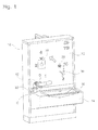
- the emptying station shown in the figures is arranged in a cabinet 10, which is made in the illustrated embodiment in sheet metal construction and has a front wall 12 from which a in the lower region of the cabinet 10 and front wall 12 arranged basin 14 projects forward.
- the cabinet 10 is created in sheet metal construction, but this is not mandatory.
- the disposal station could just as well be arranged in a masonry compartment or in or on a building, wherein the choice of material can be suitably made.
- a basin-like outlet funnel 16 may be provided with a central outlet opening on the hopper floor.
- the funnel 16 is an insert part, which can be lifted out of the basin if necessary.
- the cabinet is provided with two cabinet wings 18, 19 which are pivotally hinged to a partition wall 20, which divides the cabinet 10 into a left-hand chamber 22 and a right-hand chamber 23.
- a partition wall 20 which divides the cabinet 10 into a left-hand chamber 22 and a right-hand chamber 23.
- the right, here somewhat wider designed chamber 23 is located in the upper part of a large cistern 24 with an outlet 26, which works similar to a toilet cistern, that is provided with a water inlet and a float, so that after emptying the cistern 24th the container 24 is refilled.
- the receiving volume of the container 24 can be suitably selected.
- the container comprises 9 to 12 liters of water, this indication being not restrictive.
- the cistern may be made of sheet metal or plastic or other suitable material.
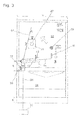
- Fig. 3 shows the front view of the disposal station analog Fig. 1 wherein the end wall 12 is provided with pictograms in the form of numbers, an arrow direction and a dripping tap, whereby the user of the disposal station is given an instruction to carry out the disposal, which will be discussed later.
- an actuator for the cistern 24 which is formed here as a push button 27 is, which is embedded in the end wall 12 and surrounded by a diaphragm 28. By pressing the push button 27, the cistern 24 can be emptied.
- a manifold 32 From the top 30 of the basin 14 is a manifold 32 upwardly, of which only a part is shown. The rest of the manifold is indicated by the line 34. This leads to a collection tank 36 placed under the corridor, which is stored mainly frost-proof and is connected to the sewerage expediently.
- the container 36 is shown only as a block diagram.
- a faucet 38 is further provided, which projects outwardly and whose water supply by a switching element, here a knob 39, can be controlled.
- the faucet 38 is connected to and fed by a central water supply line, these feeding elements being not shown in the drawing as known per se. It is sufficient to note that water can be dispensed from the central water supply via the tap 38, by actuation of the rotary knob 39.
- other switching elements are possible in a suitable manner.
- a curved pipe socket 40 is arranged above the manifold 32, on which a likewise curved receiving socket 42 is arranged.
- the curvature is expediently essentially 90 °.
- Fig. 1 denoted by arrow D.
- the receiving socket 42 according to Fig. 3 are pivoted from the receiving position shown by the dotted line 46 in a likewise shown by a dashed line 47 emptying position (and back again).
- a pivot bearing 44 any suitable pivot bearing can be selected, in the simplest case, a conventional metal clamp, as it is used for the combination of, for example, two rainwater pipes.
- the pipe socket 40 is pivoted on the manifold 32, so that the receiving port 42 from the in Fig. 1 shown position can be swung forward, especially when the recorded in the basin 14 hopper 16 is to be lifted or cleaned.
- siphons are arranged, wherein in the illustrated composite of the two lines 54 and 56 it would be sufficient to arrange a siphon 60 shown here as a block diagram in the line 58.
- any suitable siphon can be used, which prevents odor from the manifold 34 in the direction of the two basins 16 and 50 passes.
- corresponding siphons can also be provided in the other lines.
- a suspension device for a hose is expediently provided (not shown here), which can also be connected to a central water supply and opened via a tap. The hose is used to clean the pelvis 16 and 52 as well as the cabinet or the front surface of the cabinet.
- the two cabinet wings 18 and 19 are suitably closed, so that unauthorized persons access to the interior of the two chambers 22 and 23 is not possible.
- the cabinet including all lines, is designed to be frost-proof.
- a conventional heating in particular electric heating can be provided.
- the lines are thermally insulated and possibly even heated, such as by wrapped heating bands or resistance heating, which, as is well known, not shown and described in detail here. It is important that, depending on the location of the disposal station disposal a suitably frost-resistant design with conventional equipment expediently. An arrangement of the station in southern frost-free areas such additional equipment would not be required.
- the disposal station works as follows. From a caravan there is generally accessible via an opening flap and arranged below the toilet bowl toilet cassette is removed by the user and with its discharge nozzle 62, as in Fig. 6 shown schematically, inserted into the receiving socket 42.
- the toilet cassettes are here in the rule standardized, which applies in particular to the discharge nozzle 22 of the cartridge 64, the only example in Fig. 6 is shown.
- the inner diameter of the receiving nozzle 42 and the outer diameter of the drainage nozzle 62 are matched to one another such that after insertion of the in Fig. 6 partially shown in dashed lines drainage nozzle 62 of the cassette 64, a free annular gap remains.
- the inserted into the receiving socket cartridge 64 is pivoted upwards together with the receiving socket 42 about the pivot axis C upwards, and from the in Fig. 3 designated with 46 recording position in the designated 47 drainage station, which is also indicated by the dashed line 47 in Fig. 6 is indicated.
- the toilet cartridge 64 is vented, including usually a pressure valve or a push button on the cartridge is present, with the result that the contents of the cartridge 64 flows through the inserted into the receiving port 42 drainage nozzle 62 downwards, and although via the pipe 40, the manifold 32 into the manifold 34 and from there to the central tank 36.
- the filling opening of the cassette 64 is closed again with a lid and then turn the still inserted over the discharge nozzle 62 into the receiving port 42 cassette 64 is pivoted upwards in the emptying position, so that now the cleaning water from the cassette after can flow down. This will clean the cassette. Also in this cleaning process, the suction effect as a result of the annular gap between inner diameter / receiving socket and outer diameter / drainage nozzle 62, so that an odor from the laxative line is prevented.
- the empty cassette 64 removed again, ie be deducted with the discharge nozzle from the receiving nozzle 42 of the disposal station and then the discharge nozzle 62 is closed again with its lid, which is not shown here.
- the lid must be removed before inserting the drainage nozzle in the receiving socket be so that an emptying of the cassette is possible.
- this inevitably results from the fact that the outer cover diameter is always larger than the inner diameter of the receiving nozzle, that is, forcibly must be removed for the emptying process.
- the number 1 indicates the recording position. This is through the in Fig. 1 shown position of the receiving nozzle 42 shown.
- the number 2 indicates to the user that the cassette with the receiving socket 42 is to be pivoted about the pivot bearing up to position 2.
- the number 3 illustrates the user that after emptying the cassette this must be pivoted back down, then forcibly due to the positioning of the faucet 38 in the direction of the receiving port 42, the cassette with its filling opening under the tap 38, so that means of the rotary knob 39, a supply of water into the cassette can take place.
- the number 4 symbolizes that after the emptying of the cassette to the cleaning water then the push button 27 is operated to flush the manifold 37.
- the discharge nozzle Since the toilet cassettes are largely standard equipped, so the discharge nozzle have a predetermined outer diameter, always remains an annular gap between receiving nozzle 42 and drainage nozzle 62 for the adjustment of the odor-preventing suction. If for any reason a toilet cassette with a drainage nozzle 62 are used, the diameter deviates from the standard, then by means of an adapter tube which is plugged onto the drainage nozzle 62 or, if necessary, in the receiving socket 42, adapted the transition towards the desired annular gap become.
- the heating water-resistant so that it is not affected by water access, such as the cleaning process. It does not require a separate statement that the heating is suitably monitored by thermostats and the like.
- the heating is done by electric heaters, including, for example, the lines can be wrapped with heating tapes.
- alternative heating is also possible, in particular heating via a connected solar module, so that the electric heater can be supplied with power via the solar module during periods of good weather.
- the sheet metal design for the disposal station with a cabinet with corresponding cabinet wings allows mobility of the system, which thereby also can be easily installed and installed. All essential elements are easily accessible after opening the cabinet wings, so that maintenance can be carried out easier. As a result of the two basins and a proper discharge is possible. Overall, the disposal station is characterized by a simple structure, is easy to operate and protected against odor leakage and secured.
- the cassette In the recording position is, as in particular from Fig. 6 shows, the cassette in a substantially horizontal, possibly slightly inclined position, such that in any case in this receiving position feces from the cassette can not escape through the discharge nozzle 62 after removing the lid, but a tipping is required.
- a suitable adapter element is shown, which on the one hand allows a centering of the drainage nozzle 62 used to form an all-round annular gap and on the other hand, if necessary, a bridging different diameter of discharge nozzle 62.
- the outer diameter are standardized.
- an adapter element 70 could be used, which can be inserted at the front end of the receiving neck 42 and formed from a sleeve made of sheet metal or plastic, which is internally suitably provided with inwardly projecting radial ribs 72. In the illustrated embodiment, four distributed over the circumference arranged ribs 72 are provided, but this is not mandatory.
- ribs 72 could be arranged directly at the front end of the receiving nozzle, in particular if the ribs or webs 72 are designed to be flexible in order to allow a bridging of the receiving nozzle 42 against emptying nozzle 62 with different outer diameters.
- the sleeve or socket-shaped adapter element 70 is provided against an inner shoulder 74 of the receiving socket 42, so that in any case is prevented by inserting the drainage nozzle 62, that at the same time the adapter element 70 is pushed too far into the receiving socket 42.
- FIGS. 9 to 12 show two embodiments of an appropriate retention mechanism to the upwardly pivoted for the purpose of disposal inlet pipe or the outlet nozzle (see line 47) back in his FIG. 6 intimidzuschwenken apparent starting position in which the toilet cassette 64 is docked or removed again after emptying.
- FIG. 9 and 10 show a first embodiment of such a convenient return mechanism.
- the output port 42 connects, which serves to receive the toilet cassette.
- a leg spring 82 is wound, which is fixed via a bracket 84 at the disposal station. If the receiving port 42 pivoted upwards for the purpose of emptying a cassette, in the FIG. 6 dashed line 47 apparent position, then the spring 82 is biased. After the emptying is due to the spring bias of the outlet nozzle 42 back to the starting position according to FIG. 6 pivoted, in which the cassette can be removed or attached.
- FIG. 10 shows the return mechanism from a different angle, in particular, the determination of the spring leg 86 is clearly recognizable on the console 40.
- FIG. 11 and 12 show a corresponding gas spring 88. These also automatically leads the upwardly swung-out outlet port 42 back to the starting position FIG. 6 back.
- FIG. 11 shows that one end of the gas spring 88 is fixed to a leg 90 relative to the manifold 32, wherein the sleeve is again denoted by 42. If the outlet port 42 is pivoted upwards, the gas pressure spring 88 is compressed, a bias is established, which then accomplishes an automatic return of the upwardly pivoted outlet nozzle 42.
- spring mechanisms are generally known spring mechanisms.
- other return mechanisms in particular springs, are suitable.
Abstract
Description
Die Erfindung betrifft eine Entsorgungsstation gemäß dem Oberbegriff des Anspruches 1, wobei der Begriff Reisemobilie und dergleichen sehr weit zu verstehen ist, also auch Wohnmobile, Caravans, Reisebusse, Sportboote, Yachten und dergleichen mobile Einheiten betrifft, die entsprechende Kassetten für Fäkalien, Abfallwasser und dergleichen aufweisen.The invention relates to a disposal station according to the preamble of
Bekanntermaßen sind Caravans, d.h. Reisemobile, Wohnwägen und dgl. mit sanitärtechnischen und küchentechnischen Geräten und Anlagen ausgerüstet. Für die Aufnahme von Fäkalien dienen hierbei Toiletten-Kassetten, die in eingesetztem Zustand unterhalb der WC-Schüssel angeordnet sind. Die Kassetten sind über eine Öffnungsklappe von außen her zugänglich, so dass eine mit Fäkalien gefüllte Kassette zum Zwecke der Entsorgung, d.h. Entleerung und Reinigung, entnommen werden kann. Das Volumen derartiger Kassetten ist vergleichsweise hoch und auf einen Bedarf von etwa zwei Tagen ausgelegt.As is known, caravans, i. Motorhomes, caravans and the like. Equipped with sanitary and kitchen equipment and systems. For the reception of fecal matter here are toilet cassettes, which are arranged in the inserted state below the toilet bowl. The cassettes are accessible from the outside via an opening flap, so that a cassette filled with feces for the purpose of disposal, i. Emptying and cleaning, can be removed. The volume of such cassettes is comparatively high and designed for a requirement of about two days.
Zwar sind heutzutage die Caravan-Plätze entsprechend modern ausgerüstet mit Sanitärbereich einschließlich Toiletten und Duschen, Restaurantbetrieb und dergleichen mehr, jedoch bereitet nach wie vor die Entsorgung Kopfzerbrechen.Although nowadays the caravan squares are appropriately equipped with sanitary facilities including toilets and showers, restaurant operations and the like, but disposal is still a major concern.
Bis dato erfolgte im allgemeinen die Entsorgung der Toiletten-Kassetten an einem gesonderten Bereich eines Caravan-Platzes, indem die Toiletten-Kassetten über ihren Entleerungsstutzen in eine Leitung entleert werden, die an einer separaten Säule vorgesehen ist. Nach dem Entleeren kann die Kassette mit Reinigungswasser gefüllt und erneut entleert werden, so dass ein nachfolgender Reinigungsvorgang der Kassette stattfindet, bevor sie über die Versorgungsklappe am Reisemobil wieder im Toilettenbereich unterhalb der WC-Schüssel angeordnet wird.To date, the toilet cassettes have generally been disposed of at a separate area of a caravan site by emptying the toilet cassettes via their discharge ports into a conduit provided on a separate column. After emptying, the cassette can be filled with cleaning water and emptied again, so that a subsequent cleaning process of the cassette takes place before it is placed on the supply flap on the motor home again in the toilet area below the toilet bowl.
Diese Art der Entsorgung ist mühsam, hygienisch nicht einwandfrei und vor allem auch unvermeidbar mit entsprechender Geruchsbelästigung verbunden. Diese Art der Versorgung führt es auch mit sich, dass die hierfür vorgesehenen zentralen Säulen sehr oft verschmutzt sind, was teilweise zu ekelerregenden Zuständen führen kann und nicht gerade ein Vorzeichen für einen von einem Urlauber anzusteuernden Caravan-Platz darstellt.This type of disposal is laborious, hygienic not perfect and, above all, unavoidably associated with the corresponding odor nuisance. This type of care also entails that the central pillars provided for this purpose are very often polluted, which can sometimes lead to disgusting conditions and does not exactly represent a sign for a caravan space to be controlled by a holidaymaker.
Demzufolge ist dringend Abhilfe geboten, indem eine Entsorgungsstation geschaffen wird, die in einfacher und zuverlässiger sowie hygienisch einwandfreier Weise eine Entsorgung derartiger Toiletten-Kassetten von Caravans und dgl. ermöglicht. Nach einem weiteren Aspekt soll die Entsorgung insbesondere geruchsfrei erfolgen können. Auch eine einfache Reinigung soll gewährleistet sein.Accordingly, a remedy is urgently needed by a waste disposal station is created, which allows a simple and reliable and hygienic way to dispose of such toilet cassettes of caravans and the like. According to a further aspect, the disposal should be able to take place in particular odorless. Even a simple cleaning should be guaranteed.
Diese Aufgabe wird erfindungsgemäß durch die im kennzeichnenden Teil des Anspruches 1 enthaltenen Merkmale gelöst. Zweckmäßige Weiterbildungen der Erfindung sind durch die in den Unteransprüchen enthaltenen Merkmalen gekennzeichnet.This object is achieved by the features contained in the characterizing part of
Nach Maßgabe der Erfindung ist ein Aufnahmestutzen, der zur Aufnahme der Kassette über deren Entleerungsstutzen dient, der in den Aufnahmestutzen eingesteckt wird, verschwenkbar an einer zur Kanalisation oder einem Tank führenden Sammelleitung gelagert. Insbesondere ist der Aufnahmestutzen aus einer im wesentlichen horizontalen bzw. allenfalls leicht gekippten Aufnahmeposition, in der eine selbsttätige Entleerung der Kassette nicht möglich ist, in eine Kippstellung überführbar, in der die im Aufnahmestutzen eingesteckte Kassette entsprechend schräg gestellt ist, so dass diese in einfacher Weise selbsttätig entleert werden kann, sobald eine Entlüftungsöffnung an der Kassette geöffnet wird. Durch die Entlüftungsöffnung wird ein Entstehen von Unterdruck verhindert, so dass die Fäkalien nach Abnehmen des Deckels vom Entleerungsstutzen über den dann offenen Entleerungsstutzen nach unten hin über die Sammelleitung abgeführt werden können. Diese Handhabung ist denkbar einfach. Vom Entleerungsstutzen muss lediglich der Deckel abgenommen, die Kassette mit dem Entleerungsstutzen in den Aufnahmestutzen gesteckt, die Kassette dann mit dem Aufnahmestutzen nach oben in die Kippstellung verschwenkt werden, so dass dann eine rasche und saubere Entleerung der Fäkalien über die Sammelleitung möglich ist.According to the invention, a receiving socket, which serves to receive the cassette via the discharge nozzle, which is inserted into the receiving socket, pivotally mounted on a leading to the sewer or a tank manifold. In particular, the receiving socket from a substantially horizontal or possibly slightly tilted receiving position in which an automatic emptying of the cassette is not possible, can be converted into a tilted position, in which the cartridge inserted in the receiving socket is set correspondingly inclined, so that these in a simple manner can be automatically drained as soon as a vent opening on the cassette is opened. Through the vent opening, a negative pressure is prevented, so that the faeces can be removed after removing the lid from the discharge nozzle via the then open drainage nozzle down over the manifold. This handling is very simple. From the drain nozzle only the lid must be removed, the cassette with the discharge nozzle inserted into the receiving socket, the cassette then with the receiving socket be pivoted upwards in the tilted position, so that then a quick and clean emptying of the feces on the manifold is possible.
In diesem Zusammenhang ist es insbesondere zweckmäßig, wenn der Aufnahmestutzen so ausgebildet ist, dass beim Einströmen der Fäkalien aus der Kassette Umgebungsluft über geeignete Öffnungen angesaugt wird, da durch diesen Luftsog eine Geruchssperre gebildet wird. Dabei ist es zweckmäßig, wenn der Innendurchmesser des Aufnahmestutzens etwas größer ausgelegt ist als der Außendurchmesser des Entleerungsstutzens der Kassette, so dass zwischen Aufnahmestutzen und darin eingestecktem Entleerungsstutzen ein offener Luftspalt verbleibt. Wird der Aufnahmestutzen mit der eingesteckten Kassette nach oben in die Kippstellung verschwenkt, dann wird bei der Entleerung durch den Fäkalienstrom Luft aus der Umgebung in den Spalt angesaugt und nach unten in die Sammelleitung mitgerissen, wodurch zwangsweise eine sehr zuverlässige und wirksame Geruchssperre entsteht. Das heißt, während des Entleerungsvorgangs kann keinerlei Geruch nach außen hin mehr abströmen, so dass eine geruchsfreie Entleerung derartiger Fäkalienbehälter möglich ist. Es ist zweckmäßig, dass ein Ringspalt zwischen Aufnahmestutzen und Entleerungsstutzen gebildet wird, der sich günstig für einen gleichmäßig ausgebildeten Sog in Richtung Sammelleitung auswirkt. Hierzu kann bedarfsweise ein Adapterelement vorgesehen sein, beispielsweise eine Hülse mit Radialrippen, die ein zentrisches Einstecken des Entleerungsstutzens ermöglicht oder es sind Zentrierrippen, Stege oder dergleichen am Einlass des Aufnahmestutzens hierfür vorgesehen. Eine derartige Zentrierung lässt sich auch auf unterschiedliche Weise erreichen und ist bedarfsweise durchaus zweckmäßig, um einen Ringspalt zu gewährleisten. Alternativ kann auch ein Adapterstück auf den Entleerungsstützen gesteckt werden, welches nach außen vorstehende Radialrippen zur Anlage in den Innenumfang des Aufnahmestutzens aufweisen. Sind die Radialrippen aus deformierbarem Material, dann kann auch eine gute Durchmesserüberbrückung zwischen Aufnahmestutzen und Entleerungsstutzen gewährleistet werden, falls Entleerungsstutzen mit unterschiedlichen Durchmessern verwendet werden.In this context, it is particularly expedient if the receiving neck is formed so that ambient air is sucked in through suitable openings when the fecal matter flows out of the cassette, since an odor barrier is formed by this air suction. It is expedient if the inner diameter of the receiving nozzle is designed to be slightly larger than the outer diameter of the discharge nozzle of the cassette, so that an open air gap remains between receiving nozzle and inserted therein emptying nozzle. If the receiving socket with the inserted cassette is pivoted upwards into the tilted position, air is sucked from the environment into the gap during emptying by the fecal flow and entrained downwards into the collecting line, whereby a very reliable and effective odor barrier is forcibly produced. This means that during the emptying process, no odor can escape to the outside more, so that an odorless emptying of such fecal container is possible. It is expedient that an annular gap between receiving socket and drainage nozzle is formed, which has a favorable effect for a uniform suction in the direction of the manifold. For this purpose, if necessary, an adapter element may be provided, for example, a sleeve with radial ribs, which allows a centric insertion of the drainage nozzle or there are centering ribs, webs or the like provided at the inlet of the receiving nozzle for this purpose. Such a centering can also be achieved in different ways and, if necessary, quite expedient to ensure an annular gap. Alternatively, an adapter piece can be plugged onto the emptying supports, which have outwardly projecting radial ribs for abutment in the inner circumference of the receiving nozzle. If the radial ribs of deformable material, then a good diameter bridging between receiving spigot and discharge nozzle can be ensured if emptying nozzles are used with different diameters.
In zweckmäßiger Weise weist die Entsorgungsstation einen Hahn oberhalb eines von einer Stirnwand der Entsorgungsstation vorspringenden Beckens auf, der derart zweckmäßigerweise gegenüber dem Aufnahmestutzen ausgerichtet ist, dass in abgeschwenkter Stellung des Aufnahmestutzens eine daran angeordnete Kassette mit ihrer Einfüllöffnung unterhalb des Hahns zu liegen kommt und deswegen die Kassette schnell und einfach mit Reinigungswasser gefüllt werden kann. Nach Füllen der Kassette mit Reinigungswasser wird diese wieder nach oben geschwenkt, so dass die Kassette erneut entleert und dann abgeschwenkt und vom Aufnahmestutzen abgezogen werden kann. Nach Verschließen des Entleerungsstutzens mit dem Deckel kann die Kassette dann wieder in das Wohnmobil eingesetzt werden.Conveniently, the disposal station has a tap above a projecting from an end wall of the disposal basin, which is so aligned relative to the receiving socket that in the pivoted position of the receiving nozzle a arranged thereon cartridge with its filling opening below the tap comes to rest and therefore the Cassette can be filled quickly and easily with cleaning water. After filling the cassette with cleaning water this is pivoted back up so that the cassette emptied again and then swung off and can be removed from the receiving socket. After closing The cassette can then be reinserted into the RV with the lid.
Zweckmäßigerweise ist die Entsorgungsstation in Art eines Schranks oder eines vergleichbaren Kompartments, das kann auch ein Gebäude aus Mauerwerk oder Holz, etwa ein Schuppen, gebildet sein. Im Falle eines Schrankes ist dieser vorzugsweise in Blechbauweise ausgeführt. Innerhalb des Schrankes kann ferner ein Spülkasten aufgenommen sein, der zur Reinigung der Sammelleitung nach Entleerung der Kassette dient. Der Spülkasten kann hierbei beispielsweise über einen Druckknopf betätigt werden, so dass Reinigungswasser aus dem Kasten in die Sammelleitung gelangt und diese nach erfolgter Entsorgung spült. Der Spülkasten ist analog eines Toilettenspülkastens ausgebildet, d.h. mit einem Schwimmer oder dgl. versehen, so dass nach Entleeren des Spülkastens dieser über eine zentrale Wasserzufuhr erneut mit Reinigungswasser gefüllt werden kann. Zweckmäßigerweise erfolgt die Betätigung des Spülkastens über einen an einer Stirnwand der Entladungsstation bzw. des Schrankes angeordneten Druckknopf.Conveniently, the disposal station in the manner of a cabinet or a similar compartments, which may also be a building of masonry or wood, such as a shed, formed. In the case of a cabinet this is preferably carried out in sheet metal construction. Within the cabinet, a cistern may also be included, which serves to clean the manifold after emptying the cartridge. The cistern can be operated for example via a push button, so that cleaning water from the box gets into the manifold and this rinses after disposal. The cistern is analogous to a toilet cistern, i. provided with a float or the like., So that after emptying the cistern this can be filled via a central water supply again with cleaning water. Appropriately, the actuation of the cistern takes place via a arranged on an end wall of the discharge station or the cabinet push button.
Das an der Stirnwand des Schrankes vorgesehene Becken kann mit einem trichterartigen Deckel geschlossen werden, der als Auffangbecken dient, damit leicht entnehmbar und somit leicht zu reinigen ist. Abwasser, insbesondere Fäkalien, die versehentlich beim Entleeren infolge unachtsamer Handhabung herausschwappen, werden im Auffangbecken bzw. im trichterartigen Deckel aufgefangen und können über eine vorzugsweise zentrale Auslassöffnung in Richtung Sammelleitung abgeführt werden.The basin provided on the front wall of the cabinet can be closed with a funnel-like lid, which serves as a catch basin, so that it is easy to remove and thus easy to clean. Wastewater, especially faeces, spilling accidentally when emptying due to careless handling are collected in the catch basin or in the funnel-like lid and can be removed via a preferably central outlet opening towards the manifold.
Zweckmäßigerweise ist zur Meidung von Geruchsbelästigungen am freien Rohrende des Auslassstutzens 42, an dem zum Zweck der Entsorgung die Toiletten-Kassette angedockt bzw. angesteckt wird, eine Verschlusskappe vorgesehen, welche das freie Rohrende des Stutzens schließt. Zum Zweck der Entsorgung kann die Verschlusskappe manuell hochgeklappt werden, wozu sie im oberen Bereicht am Stutzen angelenkt und im übrigen zweckmäßiger Weise durch eine Feder vorgespannt ist, so dass die nach oben in die Entsorgungsstellung verschwenkte Verschlusskappe nach Abnahme der Toiletten-Kassette selbsttätig in Schließstellung nach unten verschwenkt und damit den Austritt des Ausgangsstutzens verschließt.Conveniently, to avoid odor nuisance at the free end of the
Ferner ist es zweckmäßig, einen Rückholmechanismus vorzusehen, um das zur Entleerung der angedockten Toiletten-Kassette hochgeschwenkte Einlassrohr bzw. den hochgeschwenkten Ausgangsstutzen wieder nach unten in seine Ruhestellung zu verschwenken, wo das Andocken bzw. die Wegnahme der Toiletten-Kassette erfolgt. Dies ist deswegen zweckmäßig, weil dadurch verhindert wird, dass der nächste Nutzer versehentlich die Toiletten-Kassette versucht, auf das hochgeschwenkte Rohr bzw. den hochgeschwenkten Auslassstutzen zu stecken, mit der Gefahr, dass dann Abwasser versehendlich bereits ausläuft. Der Rückholmechanismus ist zweckmäßigerweise durch eine Feder gebildet, wie etwas eine Gasdruckfeder oder eine Schenkelfeder, um nur Beispiele von geeigneten Federn zu nennen.Furthermore, it is expedient to provide a return mechanism to pivot the up to empty the docked toilet cassette inlet pipe or the swung-up outlet nozzle back down to its rest position where the docking or removal of the toilet cassette is done. This is convenient because it prevents that the next user inadvertently tries to put the toilet cassette on the swiveled pipe or the swiveled out outlet pipe, with the risk that then wastewater will be accidentally leaked. The return mechanism is conveniently formed by a spring, such as a gas spring or a leg spring, to name just examples of suitable springs.
Zweckmäßigerweise ist der Schrank in zwei Kammern unterteilt, wobei in einer der beiden Kammern der Spülkasten untergebracht ist und in der anderen Kammer im Bereich des Bodens ein weiteres Auffangbecken. In dieser Kammer mit dem Auffangbecken ist auch ein Anschluss des Wasserhahns mit der zentralen Wasserzufuhr vorgesehen, so dass beliebig Reinigungswasser gezapft werden kann. Ferner ist in diesem Schrank bzw. dieser Kammer des Schrankes eine Aufhängvorrichtung für das Aufhängen eines Schlauches vorgesehen, der über einen Anschluss mit Wasser gespeist werden kann. Der Schlauch kann dann zu Reinigungszwecken verwendet werden.Conveniently, the cabinet is divided into two chambers, wherein in one of the two chambers of the cistern is housed and in the other chamber in the region of the bottom another catch basin. In this chamber with the catch basin and a connection of the faucet with the central water supply is provided so that any cleaning water can be tapped. Furthermore, a suspension device for hanging a hose is provided in this cabinet or this chamber of the cabinet, which can be fed via a connection with water. The hose can then be used for cleaning purposes.
Bei Verwendung der Entsorgungsstation in kälteren Zonen ist es bevorzugt, auch eine entsprechende Bereitstellung der Entsorgungsstation für den Winterbetrieb zu ermöglichen. Hierzu ist zweckmäßigerweise eine Beheizung vorgesehen, mit der insbesondere der Schrank, die Leitungen und die übrigen Anlagenelemente beheizt werden können, so dass auch unter Frostbedingungen ein einwandfreier Betrieb ermöglicht ist. Zweckmäßigerweise können hierbei die Leitungen isoliert sein, ebenso wie die Schrankwände und Türen. Bei Heizungen können die Leitungen beispielsweise mit Heizbändern umwickelt sein. Vorzugsweise erfolgt die Beheizung elektrisch, wobei es auch zweckmäßig sein kann, ein oder mehrere Solarmodule der Station beizukoppeln. Im Falle der Beheizung ist es zweckmäßig, eine Regelung über Thermostate vorzusehen. Beim Einsatz der Entleerungsstation in Kältezonen versteht es sich von selbst, dass im übrigen die zur Kanalisation führenden Leitungen entsprechend frostgeschützt tief im Boden verlegt sind. Dies gilt auch für den zentralen Behälter, in den ggf. die Sammelleitung mündet.When using the disposal station in colder zones, it is preferable to allow a corresponding provision of the disposal station for winter operation. For this purpose, heating is expediently provided with which, in particular, the cabinet, the lines and the other system elements can be heated, so that even under freezing conditions perfect operation is made possible. Appropriately, in this case, the lines can be isolated, as well as the cabinet walls and doors. In heaters, the lines can be wrapped for example with heating bands. The heating is preferably carried out electrically, and it may also be expedient to add one or more solar modules to the station. In the case of heating, it is expedient to provide a control via thermostats. When using the emptying station in cold zones, it goes without saying that, moreover, the pipes leading to the sewage system are laid deep in the ground, protected against frost. This also applies to the central container into which the manifold possibly opens.
Die Erfindung bezieht sich auch auf ein Verfahren für die Entsorgung von Toiletten-Kassetten von Reisemobilen, Wohnwägen und dgl., wobei eine mit Fäkalien gefüllte Toiletten-Kassette vom Caravan bzw. Wohnwagen entfernt und in den abgeschwenkten Aufnahmestutzen der Entsorgungsstation eingesteckt und dann mit dem Aufnahmestutzen nach oben in eine Kippstellung überführt wird, so dass eine Entleerung der Kassette über die Sammelleitung möglich ist. In einem weiteren Schritt kann nach Absenken der Kassette in die Ausgangsposition diese mit Reinigungswasser gefüllt werden, um die von Fäkalien entleerte Kassette zu reinigen. Sobald die Kassette mit Wasser gefüllt ist, wird die Kassette erneut in Kippstellung mit dem schwenkbar gelagerten Aufnahmestutzen verschwenkt, so dass das Reinigungswasser entleert werden kann. Nach Absenken des Aufnahmestutzens in die Ausgangsposition, in welcher sich die Kassette im wesentlichen in horizontaler Lage in eingesteckter Stellung befindet, zumindest in so einer Lage, die eine Entleerung über den Entleerungsstutzen nicht ermöglicht, kann die Kassette abgezogen, der Entleerungsstutzen mit einem Deckel verschlossen und die Kassette wieder in den Caravan umgesetzt werden. Daraufhin erfolgt zweckmäßig ein Spülvorgang der Sammelleitung, in dem durch Betätigung des Spülkastens entsprechend Reinigungswasser in die Sammelleitung geführt wird. Ferner betrifft die Erfindung auch eine Toiletten-Kassette, die für den Einsatz in einer Entsorgungsstation gerüstet ist und insofern innerhalb eines Systems aus Entsorgungsstation mit Toiletten-Kassette genutzt wird.The invention also relates to a method for the disposal of toilet cassettes of motorhomes, caravans and the like., Which filled with feces toilet cassette from the caravan or caravan and plugged into the swung-receiving socket of the disposal station and then with the receiving socket is transferred to the top in a tilted position, so that an emptying of the cassette via the manifold is possible. In a further step, after lowering the cassette to the starting position, it can be filled with cleaning water in order to clean the cassette emptied of feces. Once the cassette is filled with water, the cassette is pivoted again in tilted position with the pivotally mounted receiving socket, so that the cleaning water can be emptied. After lowering the receiving nozzle to the starting position in which the cassette is in a substantially horizontal position in the inserted position, at least in such a situation that does not allow emptying through the discharge nozzle, the cassette can be removed, the discharge nozzle closed with a lid and the cassette will be put back into the caravan. This is followed by a purge of the manifold, in which is carried out by actuation of the cistern according to cleaning water in the manifold. Furthermore, the invention also relates to a toilet cassette, which is equipped for use in a disposal station and thus used within a system of disposal station with toilet cassette.
Damit ist eine einfache und vor allem sicherere und hygienische Entsorgung von Toiletten-Kassetten möglich, wobei die Handhabung sehr einfach und auch von einem ungeübten Benutzer ohne weiteres vorgenommen werden kann. Er muss lediglich die Kassette über den Entleerungsstutzen in den Aufnahmestutzen stecken, diesen hochklappen, so dass die Entleerung erfolgt. Die gleichen Schritte sind dann mit einem oder möglicherweise auch zwei weiteren Reinigungsvorgängen der Kassette zu vollziehen. Überdies sind alle Elemente der Station kompakt in einer Baueinheit angeordnet, können leicht gehandhabt und gewartet und im übrigen auch sehr leicht und schnell gereinigt werden.For a simple and above all safer and hygienic disposal of toilet cassettes is possible, the handling can be made very easily and easily by an untrained user. All he has to do is insert the cassette over the emptying nozzle into the receiving socket, fold it up so that emptying takes place. The same steps then have to be taken with one or possibly two further cleaning operations of the cassette. Moreover, all elements of the station are arranged compactly in a structural unit, can be easily handled and maintained and also cleaned very easily and quickly.
Nachfolgend wird ein bevorzugtes Ausführungsbeispiel der erfindungsgemäßen Entsorgungsstation anhand der Zeichnung beschrieben. Darin zeigen in rein schematischer Darstellung:
- Fig. 1:
- eine perspektivische Darstellung einer in Form eines Schranks ausgelegten Entsorgungsstation in Vorderansicht,
- Fig. 2:
- eine gleichfalls perspektivische Darstellung der Entsorgungsstation in Ansicht von der Rückseite her,
- Fig. 3:
- eine Stirnansicht der in
Fig. 1 dargestellten Entsorgungsstation, - Fig. 4:
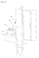
- eine Seitenansicht der Entsorgungsstation,
- Fig. 5:
- eine Schnittansicht der Entsorgungsstation gemäß Schnittlinie AA in
Fig. 4 , sowie - Fig. 6:
- eine rein schematische Darstellung nur von Teilen der Entsorgungsstation mit angeschlossener Toiletten-Kassette,
- Fig. 7:
- eine Teilansicht eines Aufnahmestutzens mit darin eingeführtem Entleerungsstutzen mit einem Schnitt in der oberen Hälfte zur Darstellung eines Adapterelements,
- Fig. 8:
- eine Stirnansicht des Adapterelements nach
Fig. 7 , - Fig. 9:
- eine perspektivische Teilansicht eines Rückholmechanismus,
- Fig. 10:
- eine weitere Darstellung gemäß
Figur 9 , - Fig. 11:
- eine Darstellung einer weiteren Ausführungsform eines Rückholmechanismus in Form einer Gasdruckfeder sowie
- Fig. 12:
- eine weitere Ansicht der Ausführungsform nach
Figur 11 , jedoch aus einem anderen Blickwinkel
- Fig. 1:
- a perspective view of designed in the form of a cabinet disposal station in front view,
- Fig. 2:
- a likewise perspective view of the disposal station in view from the back,
- 3:
- an end view of in
Fig. 1 illustrated disposal station, - 4:
- a side view of the disposal station,
- Fig. 5:
- a sectional view of the disposal station along section line AA in
Fig. 4 , such as - Fig. 6:
- a purely schematic representation of only parts of the disposal station with attached toilet cassette,
- Fig. 7:
- a partial view of a receiving nozzle with introduced therein drainage nozzle with a section in the upper half to illustrate an adapter element,
- Fig. 8:
- an end view of the adapter element according to
Fig. 7 . - Fig. 9:
- a partial perspective view of a return mechanism,
- Fig. 10:
- a further representation according to
FIG. 9 . - Fig. 11:
- a representation of another embodiment of a return mechanism in the form of a gas spring and
- Fig. 12:
- a further view of the embodiment according to
FIG. 11 but from a different angle
Die in den Figuren dargestellte Entleerungsstation ist in einem Schrank 10 angeordnet, der im dargestellten Ausführungsbeispiel in Blechbauweise erstellt ist und eine Vorderwand 12 aufweist, von der ein im unteren Bereich des Schranks 10 bzw. Vorderwand 12 angeordnetes Becken 14 nach vorne vorsteht.The emptying station shown in the figures is arranged in a
Im dargestellten Ausführungsbeispiel ist der Schrank 10 in Blechbauweise erstellt, was aber nicht zwingend ist. Die Entsorgungsstation könnte genauso gut in einem gemauerten Kompartement oder in oder an einem Gebäude angeordnet sein, wobei auch die Materialwahl geeignet getroffen werden kann.In the illustrated embodiment, the
Im Becken 14 kann ein beckenartiger Auslauftrichter 16 mit einer zentralen Auslassöffnung am Trichterboden vorgesehen sein. Der Trichter 16 ist dabei ein Einsetzteil, welches aus dem Becken bedarfsweise herausgehoben werden kann.In the
Wie sich am besten aus
Von der Oberseite 30 des Beckens 14 steht eine Sammelleitung 32 nach oben vor, von der nur ein Teil dargestellt ist. Der Rest der Sammelleitung ist durch die Linie 34 angedeutet. Diese führt zu einem unter Flur gelegten Sammeltank 36, der vornehmlich frostsicher gelagert ist und mit der Kanalisation zweckmäßigerweise verbunden ist. Der Behälter 36 ist nur als Blockschaltbild dargestellt.From the top 30 of the
An der Vorderwand 12 ist ferner auch ein Wasserhahn 38 vorgesehen, der nach außen vorsteht und dessen Wasserzufuhr durch ein Schaltelement, hier einen Drehknauf 39, geregelt werden kann. Der Wasserhahn 38 ist mit einer zentralen Wasserzufuhrleitung verbunden und darüber gespeist, wobei diese Zuführelemente als an sich bekannt nicht zeichnerisch dargestellt sind. Es genügt der Hinweis, dass über den Wasserhahn 38 entsprechend Wasser von der zentralen Wasserzufuhr gezapft werden kann, und zwar durch Betätigung des Drehknaufes 39. Selbstverständlich sind auch andere Schaltglieder in geeigneter Weise möglich.On the
Wie am besten aus
Aus der Rückansicht in
Je nachdem, in welchen Gefilden die Entsorgungsstation angeordnet ist, wird der Schrank einschließlich aller Leitungen frostsicher ausgelegt. Hierbei kann eine übliche Beheizung, insbesondere elektrische Beheizung vorgesehen sein. Zweckmäßigerweise sind hierbei auch die Leitungen wärmeisoliert und ggf. auch selbst beheizbar, etwa durch umwickelte Heizbänder oder Widerstandserhitzung, was, da allgemein bekannt, hier nicht im einzelnen gezeigt und beschrieben werden muss. Wichtig ist, dass je nach Ort der Anordnung der Entsorgungsstation eine entsprechend frostsichere Auslegung mit üblichen Ausrüstungen zweckmäßigerweise erfolgt. Bei einer Anordnung der Station in südlichen frostfreien Gefilden wäre eine solche Zusatzausrüstung nicht erforderlich.Depending on the location in which the disposal station is located, the cabinet, including all lines, is designed to be frost-proof. In this case, a conventional heating, in particular electric heating can be provided. Appropriately, in this case, the lines are thermally insulated and possibly even heated, such as by wrapped heating bands or resistance heating, which, as is well known, not shown and described in detail here. It is important that, depending on the location of the disposal station disposal a suitably frost-resistant design with conventional equipment expediently. An arrangement of the station in southern frost-free areas such additional equipment would not be required.
Im übrigen funktioniert die Entsorgungsstation wie folgt. Aus einem Caravan wird die dort allgemein über eine Öffnungsklappe zugängliche und unterhalb der WC-Schüssel angeordnete Toiletten-Kassette vom Benutzer herausgenommen und mit ihrem Entleerungsstutzen 62, wie in
Zweckmäßigerweise sind hierbei der Innendurchmesser des Aufnahmestutzens 42 und der Außendurchmesser des Entleerungsstutzens 62 derart aufeinander abgestimmt, dass nach dem Einstecken des in
Zum Zwecke des Entleerens der Kassette 64 von den darin befindlichen Fäkalien wird die in den Aufnahmestutzen eingesteckte Kassette 64 nach oben mitsamt dem Aufnahmestutzen 42 um die Schwenkachse C nach oben verschwenkt, und zwar aus der in
Selbstverständlich kann über den Wasserhahn 38 bei Betätigung des Drehknaufs 39 dann auch das Becken 16 gereinigt werden, falls beim Hantieren der Kassette Fäkalien, etwa durch unachtsame Handhabung, in den beckenförmigen Trichter 16 eingelaufen sind.Of course, then via the
Im übrigen wäre eine weitere Reinigung über den vorbeschriebenen Schlauch möglich, der in der linken Kammer 22 des Schranks 10 angeordnet ist. Da der Trichter 16 aus dem Becken 14 rausgehoben werden kann, ist auch eine einfache Reinigung des Beckens 14 möglich. Da zweckmäßigerweise auch in der Sammelleitung 34 ein Syphon vorgesehen sein kann, ist ein Geruchaustritt aus der Sammelleitung nach außen hin nicht möglich, also auch dann, wenn keine Kassette vorgesehen ist.Otherwise, a further cleaning would be possible via the hose described above, which is arranged in the left-
Nach dem Entleeren der Toiletten-Kassette kann durch Betätigung des Druckknopfes 27 der Spülkasten betätigt werden, so dass die Sammelleitung 34 durch das Reinigungswasser im Spülkasten gereinigt werden kann. Dieser Spülvorgang sollte nach jeder Kassettenentleerung stattfinden. Deswegen sind an der Stirnwand auch entsprechende Piktogramme vorgesehen. So weist die Zahl 1 auf die Aufnahmeposition hin. Diese ist durch die in
Da die Toiletten-Kassetten weitgehend standardgemäß ausgerüstet sind, also die Entleerungsstutzen einen vorgegebenen Außendurchmesser aufweisen, verbleibt stets ein Ringspalt zwischen Aufnahmestutzen 42 und Entleerungsstutzen 62 für die Einstellung des geruchsverhindernden Sogs. Sollte aus irgendeinem Grunde eine Toiletten-Kassette mit einem Entleerungsstutzen 62 verwendet werden, dessen Durchmesser abweicht vom Standard, dann kann mittels eines Adapterrohres, welches auf den Entleerungsstutzen 62 oder bedarfsweise in den Aufnahmestutzen 42 steckbar ist, der Übergang in Richtung auf den gewünschten Ringspalt angepasst werden. In einer praktischen Ausführungsform beträgt der Innendurchmesser des Aufnahmestutzens 42 71 mm und der Außendurchmesser des Entleerungsstutzens der Kassette 68 mm, so dass bei einem zentralen Einstecken ein Ringspalt in der Breite von 1,5 mm rundum verbleibt, was zweckmäßig für die Einstellung des Sogs ist.Since the toilet cassettes are largely standard equipped, so the discharge nozzle have a predetermined outer diameter, always remains an annular gap between receiving
Infolge der Isolierung und Beheizung der Leitungen ist ein Winterbetrieb der Entsorgungsstation jederzeit sicher gestellt. Selbstverständlich ist es zweckmäßig, die Heizung wasserresistent auszulegen, so dass diese durch Wasserzutritt, etwa beim Reinigungsprozess, nicht beeinträchtigt wird. Es bedarf keiner gesonderten Darlegung, dass die Heizung durch Thermostate und dergleichen geeignet überwacht wird. Zweckmäßigerweise erfolgt die Beheizung über Elektroheizungen, wozu beispielsweise auch die Leitungen mit Heizbändern umwickelt sein können. Allerdings sind auch alternative Beheizungen möglich, insbesondere eine Beheizung über ein angeschlossenes Solarmodul, so dass die Elektroheizung während Schönwetterperioden mit Strom über das Solarmodul gespeist werden kann.As a result of the insulation and heating of the lines, winter operation of the disposal station is ensured at all times. Of course, it is expedient to design the heating water-resistant, so that it is not affected by water access, such as the cleaning process. It does not require a separate statement that the heating is suitably monitored by thermostats and the like. Appropriately, the heating is done by electric heaters, including, for example, the lines can be wrapped with heating tapes. However, alternative heating is also possible, in particular heating via a connected solar module, so that the electric heater can be supplied with power via the solar module during periods of good weather.
Ebenfalls nicht beschrieben, aber bedarfsweise anwendbar, ist die Auslegung der Entsorgungsstation über entsprechende Münzeinwurfschlitze, so dass darüber die Wasserentnahme geregelt werden kann. Dies betrifft insbesondere die Wasserzufuhr über den Hahn 38.Also not described, but if necessary applicable, is the design of the disposal station via appropriate coin insertion slots, so that it can be controlled the water extraction. This relates in particular to the supply of water via the
Die Blechbauweise für die Entsorgungsstation mit einem Schrank mit entsprechenden Schrankflügeln ermöglicht eine Mobilität der Anlage, die dadurch im übrigen auch leichter aufgestellt und installiert werden kann. Alle wesentlichen Elemente sind ohne weiteres nach Öffnen der Schrankflügel zugänglich, so dass Wartungsarbeiten einfacher ausgeführt werden können. Infolge der beiden Becken ist auch eine einwandfreie Abfuhr ermöglicht. Die Entsorgungsstation zeichnet sich insgesamt durch einen einfachen Aufbau aus, ist einfach zu betätigen und insgesamt gegen Geruchsaustritt geschützt und gesichert.The sheet metal design for the disposal station with a cabinet with corresponding cabinet wings allows mobility of the system, which thereby also can be easily installed and installed. All essential elements are easily accessible after opening the cabinet wings, so that maintenance can be carried out easier. As a result of the two basins and a proper discharge is possible. Overall, the disposal station is characterized by a simple structure, is easy to operate and protected against odor leakage and secured.
In der Aufnahmeposition befindet sich, wie insbesondere aus
Anhand der
Im dargestellten Ausführungsbeispiel ist das hülsen- oder buchsenförmige Adapterelement 70 gegen eine Innenschulter 74 des Aufnahmestutzens 42 gestellt, so dass mit Einstecken des Entleerungsstutzens 62 jedenfalls verhindert wird, dass zugleich das Adapterelement 70 zu weit in den Aufnahmestutzen 42 geschoben wird.In the illustrated embodiment, the sleeve or socket-shaped
Die
Die
Aus
Das es sich bei den Federmechanismen um allgemein bekannte Federmechanismen handelt, genügt eine schematische Darstellung. Selbstverständlich sind auch andere Rückholmechanismen, insbesondere Federn, geeignet.The fact that the spring mechanisms are generally known spring mechanisms is sufficient for a schematic representation. Of course, other return mechanisms, in particular springs, are suitable.
Claims (17)
dadurch gekennzeichnet, dass
der Aufnahmestutzen (42) gegenüber der Sammelleitung (34) aus einer Aufnahmeposition (46), in welcher die Kassette mit ihrem Entleerungsstutzen (62) in den Aufnahmestutzen (42) einsteckbar ist, in eine gekippte Entleerungsposition (47) zur Entleerung einer in den Aufnahmestutzen (42) eingesetzten Kassette (64) verschwenkbar ist, in welcher der Aufnahmestutzen (42) mindestens unter einem spitzen Winkel von mehr als 55° zur Horizontalen geneigt ist.Disposal station for the disposal of toilet cassettes (64) of motorhomes, caravans, boats and the like, having a receiving stub (42) connected to a manifold (34) leading to a central tank (36) or a sewer,
characterized in that
the receiving socket (42) relative to the collecting line (34) from a receiving position (46) in which the cassette with its discharge nozzle (62) in the receiving socket (42) can be inserted, in a tilted emptying position (47) for emptying into the receiving socket (42) inserted cassette (64) is pivotable, in which the receiving socket (42) is inclined at least at an acute angle of more than 55 ° to the horizontal.
dadurch gekennzeichnet, dass
der Kippwinkel zur Horizontalen im Bereich von 60° bis 120°, insbesondere vorzugsweise von 70° bis 90° liegt.Station according to claim 1,
characterized in that
the tilt angle to the horizontal in the range of 60 ° to 120 °, in particular preferably from 70 ° to 90 °.
dadurch gekennzeichnet, dass
der Aufnahmestutzen (42) vor einer Stirnwand (12) der Entleerungsstation angeordnet und über ein Schwenklager (44) mit der abführenden Sammelleitung (34) verbunden ist, vorzugsweise über einen Krümmer des Aufnahmestutzens (42) mit einem an der Sammelleitung angeordneten gekrümmten Rohrstutzen (40) verbunden ist, der vorzugsweise an der vertikalen Sammelleitung (34) angelenkt und damit um eine Vertikale verschwenkbar ist.Station according to claim 1 or 2,
characterized in that
the receiving socket (42) is arranged in front of an end wall (12) of the emptying station and connected to the discharging collecting line (34) via a pivot bearing (44), preferably via a manifold of the receiving nozzle (42) with a curved pipe socket (40) arranged on the collecting line ), which is preferably articulated to the vertical bus (34) and thus pivotable about a vertical.
dadurch gekennzeichnet, dass
die Entleerungsstation ein von einer Stirnwand (12) der Station vorstehendes Becken (14) aufweist, von dem vorzugsweise die Sammelleitung mit dem daran angeordneten Aufnahmestutzen (42) nach oben vorsteht, und dass vorzugsweise das Auffangbecken (14) mit einem abnehmbaren trichterartigen Auslass (16) mit einer Auslassöffnung versehen ist, und dass der Beckenauslass über eine Leitung (48) mit der Sammelleitung (34) verbunden ist.Station according to one of the preceding claims,
characterized in that
the emptying station has a basin (14) protruding from an end wall (12) of the station, preferably protruding upwardly from the collecting line with the receiving spigot (42) disposed thereon, and preferably the collecting basin (14) having a removable funnel-like outlet (16 ) is provided with an outlet opening, and that the basin outlet via a line (48) is connected to the manifold (34).
dadurch gekennzeichnet, dass
oberhalb des Beckens (14) ein mit einer zentralen Wasserzufuhr verbundener Wasserhahn (38) mit einem insbesondere als Drehknauf (39) ausgebildeten Stellglied zum Öffnen und Schließen des Hahns (38) vorgesehen ist, und dass vorzugsweise der Aufnahmestutzen (42) mit dem Wasserhahn (38) derart ausgerichtet ist, dass die Einfüllöffnung einer in den Aufnahmestutzen (42) gesteckten Kassette (64) in abgeschwenkter Aufnahmeposition (46) mit dem Hahn (38) zum Zwecke der Befüllung mit Reinigungswasser ausgerichtet ist.Station according to one of the preceding claims,
characterized in that
above the basin (14) connected to a central water supply faucet (38) is provided with an in particular as a rotary knob (39) formed actuator for opening and closing the cock (38), and that preferably the receiving nozzle (42) with the faucet ( 38) is aligned such that the filling opening of a cartridge (64) inserted into the receiving socket (42) is aligned with the cock (38) in the swiveled-down receiving position (46) for the purpose of filling with cleaning water.
dadurch gekennzeichnet, dass
mit der abführenden Sammelleitung (34) ein Spülkasten (24) verbunden ist, der vorzugsweise über ein Schwimmersystem mit einer zentralen Wasserzufuhr zum Zwecke der Befüllung des Spülkastens verbunden und zur Reinigung der Sammelleitung (34) durch Betätigung eines Stellglieds, insbesondere eines Druckknopfs (27) entleerbar ist.Station according to one of the preceding claims,
characterized in that
a cistern (24) is connected to the discharge manifold (34), which is preferably connected via a float system with a central water supply for the purpose of filling the cistern and for cleaning the collecting line (34) by actuation of an actuator, in particular a push button (27) can be emptied.
dadurch gekennzeichnet, dass
die Entsorgungsstation als Schrank (10) ausgebildet ist, der an seiner Vorderseite die Stirnwand (12) mit nach außen vorstehenden Hahn (38) und das Auffangbecken (14) aufweist, und dass der Schrank vorzugsweise in Blechbauweise ausgeführt ist, und/oder dass vorzugsweise innerhalb des Schranks (10) der Spülkasten (24) aufgenommen ist, dass der Schrank (10) vorzugsweise durch eine Trennwand (20) in zwei Kammern (22, 23) unterteilt ist, wobei vorzugsweise in einer der beiden Kammern (23) der Spülkasten (24) aufgenommen ist und vorzugsweise in der anderen Kammer (22) im Bodenbereich ein weiteres Auffangbecken (50) mit einer Auslassöffnung (52) vorgesehen ist.Station according to one of the preceding claims,
characterized in that
the disposal station is formed as a cabinet (10) having on its front side the end wall (12) with outwardly projecting cock (38) and the catch basin (14), and that the cabinet is preferably designed in sheet metal construction, and / or that preferably within the cabinet (10) the cistern (24) is accommodated, that the cabinet (10) preferably by a partition (20) into two chambers (22, 23) is divided, preferably in one of the two chambers (23) of the cistern (24) is included and preferably in the other chamber (22) in the bottom area a further catch basin (50) with an outlet opening (52) is provided.
dadurch gekennzeichnet, dass
die beiden Becken (14, 50) über ihre Auslässe (49, 52) und daran angeschlossenen Leitungen (54, 56) mit der Sammelleitung (34) verbunden sind, und dass vorzugsweise die zur Sammelleitung (34) führenden Leitungen (54, 56) mit einem Syphon (60) für eine Geruchssperre versehen sind.Station according to one of the preceding claims,
characterized in that
the two basins (14, 50) are connected via their outlets (49, 52) and lines (54, 56) connected thereto to the collecting line (34), and that preferably the lines (54, 56) leading to the collecting line (34) equipped with a siphon (60) for an odor barrier.
dadurch gekennzeichnet, dass
die beiden Kammern (22, 23) des Schranks (10) jeweils durch einen Schrankflügel (18, 19) schließbar sind, und/oder dass vorzugsweise in einer der beiden Kammern (22 oder 23), insbesondere der mit dem Auffangbecken (50) versehenen Kammer (22) der Anschluss für den Wasserhahn (38) und ein Anschluss für einen Wasserschlauch zu Reinigungszwecken vorgesehen ist.Station according to one of the preceding claims,
characterized in that
the two chambers (22, 23) of the cabinet (10) each by a cabinet wing (18, 19) are closable, and / or that preferably in one of the two chambers (22 or 23), in particular provided with the catch basin (50) Chamber (22) the connection for the faucet (38) and a connection for a water hose is provided for cleaning purposes.
dadurch gekennzeichnet, dass
die Kippstellung des Aufnahmestutzens (42) nach oben durch einen mit dem Aufnahmestutzen (42) oder der Kassette (62) zusammenwirkenden Anschlag begrenzt ist.Station according to one of the preceding claims,
characterized in that
the tilted position of the receiving nozzle (42) is bounded at the top by a stop cooperating with the receiving socket (42) or the cassette (62).
dadurch gekennzeichnet, dass
das freie Ende des Aufnahmestutzens (42) durch eine verschwenkbare Verschlusskappe verschließbar ist, welche vorzugsweise in die Schließstellung durch eine Feder vorgespannt ist.Station according to one of the preceding claims,
characterized in that
the free end of the receiving neck (42) can be closed by a pivotable cap is, which is preferably biased in the closed position by a spring.
dadurch gekennzeichnet, dass
zwischen dem Aufnahmestutzen (42) und dem Entleerungsrohr (62) einer in den Entleerungsstutzen eingesetzten Kassette (64) ein offener Luftspalt oder mindestens eine Öffnung verbleibt, derart, dass bei der Entleerung der Kassette infolge der abströmenden Fäkalien ein Luftsog in Richtung Aufnahmestutzen als Geruchssperre erzeugt wird.Station according to one of the preceding claims,
characterized in that
an open air gap or at least one opening remains between the receiving stub (42) and the emptying tube (62) of a cassette (64) inserted into the emptying stub, such that when the cassette is emptied as a result of the outflowing faeces an air suction is generated in the direction of the receiving stub as an odor barrier becomes.
dadurch gekennzeichnet, dass
der Spalt durch einen Ringspalt zwischen Aufnahmestutzen (42) und Entleerungsstutzen (62) gebildet ist, wobei die Spaltbreite vorzugsweise 1 bis 4mm beträgt.Station according to claim 12,
characterized in that
the gap is formed by an annular gap between receiving socket (42) and emptying nozzle (62), wherein the gap width is preferably 1 to 4 mm.
dadurch gekennzeichnet, dass
der Schrank (10) einschließlich der Leitungen, der Wasserzufuhr und mindestens dem über Flur liegenden Teil der Sammelleitung für einen frostsicheren Betrieb beheizbar ist, wobei die Beheizung vorzugsweise über eine Elektroheizung erfolgt, die insbesondere mit einem Solarmodul koppelbar ist.Station according to one of the preceding claims,
characterized in that
the cabinet (10) including the lines, the water supply and at least lying over the corridor part of the manifold for a frost-proof operation is heated, wherein the heating is preferably via an electric heater, which is in particular coupled to a solar module.
dadurch gekennzeichnet, dass
ein Rückholmechanismus vorgesehen ist, um den Ausgangsstutzen (42) aus einer nach oben geschwenkten Stellung für die Entleerung in seine Ausgangsstellung nach unten zurück zu schwenken, vorzugsweise in Form von Federn, insbesondere Gasdruckfedern (88) oder Schenkelfedern (82).Station according to one of the preceding claims,
characterized in that
a return mechanism is provided for pivoting down the outlet port (42) from an upwardly pivoted position for emptying to its initial position, preferably in the form of springs, in particular gas springs (88) or leg springs (82).
Applications Claiming Priority (1)
| Application Number | Priority Date | Filing Date | Title |
|---|---|---|---|
| DE102013003070.6A DE102013003070A1 (en) | 2013-02-22 | 2013-02-22 | Disposal station for the disposal of toilet cassettes of motorhomes, caravans and the like |
Publications (2)
| Publication Number | Publication Date |
|---|---|
| EP2770129A2 true EP2770129A2 (en) | 2014-08-27 |
| EP2770129A3 EP2770129A3 (en) | 2015-08-19 |
Family
ID=49726482
Family Applications (1)
| Application Number | Title | Priority Date | Filing Date |
|---|---|---|---|
| EP13194619.6A Withdrawn EP2770129A3 (en) | 2013-02-22 | 2013-11-27 | Disposal station for the disposal of toilet cartridges of motorhomes, caravans and the like |
Country Status (2)
| Country | Link |
|---|---|
| EP (1) | EP2770129A3 (en) |
| DE (1) | DE102013003070A1 (en) |
Cited By (2)
| Publication number | Priority date | Publication date | Assignee | Title |
|---|---|---|---|---|
| WO2016071940A1 (en) * | 2014-11-06 | 2016-05-12 | Nitti Sergio | Automated system for draining, cleaning and sanitizing of portable toilet sewage holding tanks used in recreational vehicles such as campers, caravans, motorhomes and boats |
| FR3126718A1 (en) * | 2021-09-07 | 2023-03-10 | François LE GARSMEUR | Contactless emptying terminal for chemical cassettes |
Families Citing this family (2)
| Publication number | Priority date | Publication date | Assignee | Title |
|---|---|---|---|---|
| DE202017101065U1 (en) * | 2017-02-24 | 2018-05-25 | Hugo Vogelsang Maschinenbau Gmbh | Disposal station for a vehicle |
| US11084071B2 (en) | 2017-02-24 | 2021-08-10 | Vogelsang Gmbh & Co Kg | Suction device for wastewater tank and disposal station for a vehicle |
Family Cites Families (9)
| Publication number | Priority date | Publication date | Assignee | Title |
|---|---|---|---|---|
| DE4201074A1 (en) * | 1991-01-18 | 1992-07-23 | Ctv Chemische Toiletten Vermie | Service station for portable lavatories - has tanks for waste water, fresh water, and chemicals |
| US5318275A (en) * | 1992-01-21 | 1994-06-07 | Thetford Corporation | Portable waste holding tank with improved inlet valve assembly |
| DE19844354B4 (en) * | 1997-11-20 | 2006-11-09 | Jörg Steimer | Sewer and faeces receiving shaft for sewage and faeces |
| DE10018711A1 (en) * | 1999-09-16 | 2001-03-22 | Knaus Gmbh Jandelsbrunn | Supply and waste disposal unit for camping sites, has column shaped body with supply unit for power and fresh water, together with disposal unit for contaminated water |
| DE20308586U1 (en) * | 2003-06-02 | 2003-11-13 | Schell Herwig | A portable toilet waste tank disposal station has automatic emptying, rinsing and drying facilities with little user involvement. |
| DE20314895U1 (en) * | 2003-09-24 | 2004-02-12 | Elomat-Elektromechanische Antriebstechnik Vertriebs-Gmbh | Water supply station is particularly for camping and/or building sites and has shaft for underground installation in which water feed conduit cut-off component is located in frost-free ground level |
| DE102010005130B4 (en) * | 2010-01-19 | 2014-02-27 | Ralf Tebartz | Cleaning apparatus and method for cleaning toilets for recreational vehicles |
| DE102010032852B4 (en) * | 2010-07-30 | 2016-05-25 | Christoph Antes | Service station for disposal of faeces and / or greywater of motoring vehicles |
| DE202012007073U1 (en) * | 2012-07-23 | 2012-11-15 | Beckmann Gmbh | Disposal device, in particular disposal column |
-
2013
- 2013-02-22 DE DE102013003070.6A patent/DE102013003070A1/en not_active Withdrawn
- 2013-11-27 EP EP13194619.6A patent/EP2770129A3/en not_active Withdrawn
Non-Patent Citations (1)
| Title |
|---|
| None |
Cited By (4)
| Publication number | Priority date | Publication date | Assignee | Title |
|---|---|---|---|---|
| WO2016071940A1 (en) * | 2014-11-06 | 2016-05-12 | Nitti Sergio | Automated system for draining, cleaning and sanitizing of portable toilet sewage holding tanks used in recreational vehicles such as campers, caravans, motorhomes and boats |
| US20170335558A1 (en) * | 2014-11-06 | 2017-11-23 | Sergio Nitti | Automated system for draining, cleaning and sanitizing of portable toilet sewage holding tank used in recreational vehicles such as campers, caravans, boats etc. |
| US10557260B2 (en) * | 2014-11-06 | 2020-02-11 | Sergio Nitti | Automated system for draining, cleaning and sanitizing of portable toilet sewage holding tank used in recreational vehicles such as campers, caravans, boats etc |
| FR3126718A1 (en) * | 2021-09-07 | 2023-03-10 | François LE GARSMEUR | Contactless emptying terminal for chemical cassettes |
Also Published As
| Publication number | Publication date |
|---|---|
| EP2770129A3 (en) | 2015-08-19 |
| DE102013003070A1 (en) | 2014-08-28 |
Similar Documents
| Publication | Publication Date | Title |
|---|---|---|
| DE69817141T3 (en) | Vacuum toilet system in an airplane | |
| EP0219622B1 (en) | Device for controlling at least one gas flow | |
| EP2226438A2 (en) | Method and cistern for supplying an additive in such a cistern | |
| EP2247798B1 (en) | Usable water usage device | |
| DE2933102A1 (en) | DEVICE FOR RAILWAY VEHICLES OR THE LIKE FOR THE STORAGE AND DISPOSAL OF HUMAN ELECTRIC SUBSTANCES | |
| EP3816355B1 (en) | Separation toilet, separation toilet system and use | |
| EP2770129A2 (en) | Disposal station for the disposal of toilet cartridges of motorhomes, caravans and the like | |
| DE202021100010U1 (en) | Kit for converting a cassette toilet | |
| DE2423561A1 (en) | Toilet and washroom for caravan - with pull-out design to increase room and with external access to service WC | |
| DE102005014931B4 (en) | Waste disposal in motorhomes or the like | |
| DE202019005509U1 (en) | Separating toilet, Separating toilet system and uses | |
| DE19844354B4 (en) | Sewer and faeces receiving shaft for sewage and faeces | |
| EP3702235B1 (en) | Supply device for mobile sanitary cells | |
| DE102013007408B4 (en) | Emptying and cleaning station with recording cassette | |
| DE10100962A1 (en) | Toilet especially for aircraft has foil placed inside pan and moved to collecting pipe through transport screw mounted in disposal opening | |
| DE102006048113B4 (en) | Method and device for using tap water | |
| EP0565483B1 (en) | Basin in a waste water plant | |
| CH701009A2 (en) | Sanitary arrangement i.e. toilet, has installation apparatus i.e. flushing tank, covered with covering plate, where covering plate is pivotingly mounted with sanitary body for inspection of installation apparatus | |
| EP0989247A1 (en) | Self-cleaning toilet system | |
| DE102012011571A1 (en) | Flexible insertable device for avoiding spreading of odor in direct environment of waste disposal system for disposal of feces from portable feces containers of house toilet, has covering including opening, which opens into disposal system | |
| DE3442565A1 (en) | Sewage-conveying system | |
| DE202004011747U1 (en) | Toilet for cleaning the anal region comprises a washing device directly or indirectly supplied with water via a supply line and provided with a separating device preventing water flowing from the washing device back into the supply line | |
| DE2514452C2 (en) | WASTE WATER LIFT DEVICE, IN PARTICULAR FOR WASTE CONTAINING FAECALIA | |
| DE102013007397B4 (en) | Shower separation toilet | |
| DE202013006678U1 (en) | disposal device |
Legal Events
| Date | Code | Title | Description |
|---|---|---|---|
| PUAI | Public reference made under article 153(3) epc to a published international application that has entered the european phase |
Free format text: ORIGINAL CODE: 0009012 |
|
| 17P | Request for examination filed |
Effective date: 20131127 |
|
| AK | Designated contracting states |
Kind code of ref document: A2 Designated state(s): AL AT BE BG CH CY CZ DE DK EE ES FI FR GB GR HR HU IE IS IT LI LT LU LV MC MK MT NL NO PL PT RO RS SE SI SK SM TR |
|
| AX | Request for extension of the european patent |
Extension state: BA ME |
|
| PUAL | Search report despatched |
Free format text: ORIGINAL CODE: 0009013 |
|
| AK | Designated contracting states |
Kind code of ref document: A3 Designated state(s): AL AT BE BG CH CY CZ DE DK EE ES FI FR GB GR HR HU IE IS IT LI LT LU LV MC MK MT NL NO PL PT RO RS SE SI SK SM TR |
|
| AX | Request for extension of the european patent |
Extension state: BA ME |
|
| RIC1 | Information provided on ipc code assigned before grant |
Ipc: E03F 1/00 20060101AFI20150713BHEP Ipc: B08B 9/08 20060101ALI20150713BHEP |
|
| STAA | Information on the status of an ep patent application or granted ep patent |
Free format text: STATUS: THE APPLICATION IS DEEMED TO BE WITHDRAWN |
|
| 18D | Application deemed to be withdrawn |
Effective date: 20160220 |