EP2797152A1 - Matériau d'électrolyte solide à base de sulfure, batterie, et procédé de production d'un matériau d'électrolyte solide à base de sulfure - Google Patents
Matériau d'électrolyte solide à base de sulfure, batterie, et procédé de production d'un matériau d'électrolyte solide à base de sulfure Download PDFInfo
- Publication number
- EP2797152A1 EP2797152A1 EP12860207.5A EP12860207A EP2797152A1 EP 2797152 A1 EP2797152 A1 EP 2797152A1 EP 12860207 A EP12860207 A EP 12860207A EP 2797152 A1 EP2797152 A1 EP 2797152A1
- Authority
- EP
- European Patent Office
- Prior art keywords
- solid electrolyte
- sulfide solid
- electrolyte material
- mentioned
- peak
- Prior art date
- Legal status (The legal status is an assumption and is not a legal conclusion. Google has not performed a legal analysis and makes no representation as to the accuracy of the status listed.)
- Granted
Links
- 239000000463 material Substances 0.000 title claims abstract description 230
- 239000002203 sulfidic glass Substances 0.000 title claims abstract description 212
- 238000004519 manufacturing process Methods 0.000 title description 3
- 150000002500 ions Chemical class 0.000 claims abstract description 114
- 238000002441 X-ray diffraction Methods 0.000 claims abstract description 33
- 239000000203 mixture Substances 0.000 claims description 90
- 239000013078 crystal Substances 0.000 claims description 77
- 239000004020 conductor Substances 0.000 claims description 49
- 239000006182 cathode active material Substances 0.000 claims description 35
- 238000000034 method Methods 0.000 claims description 35
- 239000002994 raw material Substances 0.000 claims description 35
- 239000006183 anode active material Substances 0.000 claims description 33
- 238000010438 heat treatment Methods 0.000 claims description 29
- 230000002194 synthesizing effect Effects 0.000 claims description 21
- 229910052782 aluminium Inorganic materials 0.000 claims description 16
- 229910052698 phosphorus Inorganic materials 0.000 claims description 16
- 229910052710 silicon Inorganic materials 0.000 claims description 16
- 229910052732 germanium Inorganic materials 0.000 claims description 15
- 229910052718 tin Inorganic materials 0.000 claims description 15
- 229910052796 boron Inorganic materials 0.000 claims description 14
- 239000003792 electrolyte Substances 0.000 claims description 14
- 229910052738 indium Inorganic materials 0.000 claims description 14
- 229910052719 titanium Inorganic materials 0.000 claims description 14
- 229910052726 zirconium Inorganic materials 0.000 claims description 14
- 229910052787 antimony Inorganic materials 0.000 claims description 13
- 229910052733 gallium Inorganic materials 0.000 claims description 13
- 229910052758 niobium Inorganic materials 0.000 claims description 13
- 229910052720 vanadium Inorganic materials 0.000 claims description 13
- 238000003701 mechanical milling Methods 0.000 claims description 11
- 230000002349 favourable effect Effects 0.000 abstract description 16
- 239000012071 phase Substances 0.000 description 46
- GLNWILHOFOBOFD-UHFFFAOYSA-N lithium sulfide Chemical compound [Li+].[Li+].[S-2] GLNWILHOFOBOFD-UHFFFAOYSA-N 0.000 description 28
- 230000000052 comparative effect Effects 0.000 description 18
- 229910001416 lithium ion Inorganic materials 0.000 description 17
- 239000007784 solid electrolyte Substances 0.000 description 17
- 229910019638 S1-yOy Inorganic materials 0.000 description 15
- QVGXLLKOCUKJST-UHFFFAOYSA-N atomic oxygen Chemical compound [O] QVGXLLKOCUKJST-UHFFFAOYSA-N 0.000 description 12
- 229910052760 oxygen Inorganic materials 0.000 description 12
- 239000001301 oxygen Substances 0.000 description 12
- 239000010936 titanium Substances 0.000 description 11
- 229910020343 SiS2 Inorganic materials 0.000 description 10
- 229910000921 lithium phosphorous sulfides (LPS) Inorganic materials 0.000 description 10
- 238000005259 measurement Methods 0.000 description 10
- 238000001228 spectrum Methods 0.000 description 10
- FUJCRWPEOMXPAD-UHFFFAOYSA-N lithium oxide Chemical compound [Li+].[Li+].[O-2] FUJCRWPEOMXPAD-UHFFFAOYSA-N 0.000 description 9
- 229910001947 lithium oxide Inorganic materials 0.000 description 9
- 239000000126 substance Substances 0.000 description 8
- OKTJSMMVPCPJKN-UHFFFAOYSA-N Carbon Chemical compound [C] OKTJSMMVPCPJKN-UHFFFAOYSA-N 0.000 description 7
- UCKMPCXJQFINFW-UHFFFAOYSA-N Sulphide Chemical compound [S-2] UCKMPCXJQFINFW-UHFFFAOYSA-N 0.000 description 7
- 239000011230 binding agent Substances 0.000 description 6
- 239000011244 liquid electrolyte Substances 0.000 description 6
- 229910052744 lithium Inorganic materials 0.000 description 6
- 239000008188 pellet Substances 0.000 description 6
- 239000000843 powder Substances 0.000 description 6
- 239000010453 quartz Substances 0.000 description 6
- VYPSYNLAJGMNEJ-UHFFFAOYSA-N silicon dioxide Inorganic materials O=[Si]=O VYPSYNLAJGMNEJ-UHFFFAOYSA-N 0.000 description 6
- 229910011788 Li4GeS4 Inorganic materials 0.000 description 5
- 229910011889 Li4SiS4 Inorganic materials 0.000 description 5
- WHXSMMKQMYFTQS-UHFFFAOYSA-N Lithium Chemical compound [Li] WHXSMMKQMYFTQS-UHFFFAOYSA-N 0.000 description 5
- 239000012300 argon atmosphere Substances 0.000 description 5
- 229910052799 carbon Inorganic materials 0.000 description 5
- 239000002227 LISICON Substances 0.000 description 4
- 229910006962 Li(4-x)Ge(1-x)PxS4 Inorganic materials 0.000 description 4
- 229910006998 Li(4−x)Ge(1−x)PxS4 Inorganic materials 0.000 description 4
- -1 LiPF6 Chemical class 0.000 description 4
- PXHVJJICTQNCMI-UHFFFAOYSA-N Nickel Chemical compound [Ni] PXHVJJICTQNCMI-UHFFFAOYSA-N 0.000 description 4
- NINIDFKCEFEMDL-UHFFFAOYSA-N Sulfur Chemical compound [S] NINIDFKCEFEMDL-UHFFFAOYSA-N 0.000 description 4
- MCMNRKCIXSYSNV-UHFFFAOYSA-N Zirconium dioxide Chemical compound O=[Zr]=O MCMNRKCIXSYSNV-UHFFFAOYSA-N 0.000 description 4
- 238000005280 amorphization Methods 0.000 description 4
- 239000012298 atmosphere Substances 0.000 description 4
- 150000001875 compounds Chemical class 0.000 description 4
- 229910003002 lithium salt Inorganic materials 0.000 description 4
- 159000000002 lithium salts Chemical class 0.000 description 4
- 239000003960 organic solvent Substances 0.000 description 4
- 239000006104 solid solution Substances 0.000 description 4
- 229910052717 sulfur Inorganic materials 0.000 description 4
- 239000011593 sulfur Substances 0.000 description 4
- 238000012360 testing method Methods 0.000 description 4
- 230000003247 decreasing effect Effects 0.000 description 3
- 230000000694 effects Effects 0.000 description 3
- 238000011156 evaluation Methods 0.000 description 3
- 238000000465 moulding Methods 0.000 description 3
- 238000001308 synthesis method Methods 0.000 description 3
- ZZXUZKXVROWEIF-UHFFFAOYSA-N 1,2-butylene carbonate Chemical compound CCC1COC(=O)O1 ZZXUZKXVROWEIF-UHFFFAOYSA-N 0.000 description 2
- OIFBSDVPJOWBCH-UHFFFAOYSA-N Diethyl carbonate Chemical compound CCOC(=O)OCC OIFBSDVPJOWBCH-UHFFFAOYSA-N 0.000 description 2
- KMTRUDSVKNLOMY-UHFFFAOYSA-N Ethylene carbonate Chemical compound O=C1OCCO1 KMTRUDSVKNLOMY-UHFFFAOYSA-N 0.000 description 2
- XEEYBQQBJWHFJM-UHFFFAOYSA-N Iron Chemical compound [Fe] XEEYBQQBJWHFJM-UHFFFAOYSA-N 0.000 description 2
- 229910010953 LiGePS Inorganic materials 0.000 description 2
- 239000011149 active material Substances 0.000 description 2
- PNEYBMLMFCGWSK-UHFFFAOYSA-N aluminium oxide Inorganic materials [O-2].[O-2].[O-2].[Al+3].[Al+3] PNEYBMLMFCGWSK-UHFFFAOYSA-N 0.000 description 2
- 239000002388 carbon-based active material Substances 0.000 description 2
- 238000011161 development Methods 0.000 description 2
- JBTWLSYIZRCDFO-UHFFFAOYSA-N ethyl methyl carbonate Chemical compound CCOC(=O)OC JBTWLSYIZRCDFO-UHFFFAOYSA-N 0.000 description 2
- 239000011261 inert gas Substances 0.000 description 2
- 239000010416 ion conductor Substances 0.000 description 2
- 239000002931 mesocarbon microbead Substances 0.000 description 2
- 229910052751 metal Inorganic materials 0.000 description 2
- 239000002184 metal Substances 0.000 description 2
- 229910052759 nickel Inorganic materials 0.000 description 2
- 239000002245 particle Substances 0.000 description 2
- CYQAYERJWZKYML-UHFFFAOYSA-N phosphorus pentasulfide Chemical compound S1P(S2)(=S)SP3(=S)SP1(=S)SP2(=S)S3 CYQAYERJWZKYML-UHFFFAOYSA-N 0.000 description 2
- 229920000139 polyethylene terephthalate Polymers 0.000 description 2
- 239000005020 polyethylene terephthalate Substances 0.000 description 2
- 229920001343 polytetrafluoroethylene Polymers 0.000 description 2
- 239000004810 polytetrafluoroethylene Substances 0.000 description 2
- RUOJZAUFBMNUDX-UHFFFAOYSA-N propylene carbonate Chemical compound CC1COC(=O)O1 RUOJZAUFBMNUDX-UHFFFAOYSA-N 0.000 description 2
- 238000007789 sealing Methods 0.000 description 2
- 239000007787 solid Substances 0.000 description 2
- 238000010532 solid phase synthesis reaction Methods 0.000 description 2
- 239000000243 solution Substances 0.000 description 2
- 239000007858 starting material Substances 0.000 description 2
- 238000012916 structural analysis Methods 0.000 description 2
- 238000005303 weighing Methods 0.000 description 2
- 229910052725 zinc Inorganic materials 0.000 description 2
- 229920000049 Carbon (fiber) Polymers 0.000 description 1
- RYGMFSIKBFXOCR-UHFFFAOYSA-N Copper Chemical compound [Cu] RYGMFSIKBFXOCR-UHFFFAOYSA-N 0.000 description 1
- YCKRFDGAMUMZLT-UHFFFAOYSA-N Fluorine atom Chemical compound [F] YCKRFDGAMUMZLT-UHFFFAOYSA-N 0.000 description 1
- 229910005871 GeS4 Inorganic materials 0.000 description 1
- 229910008706 Li2NiMn3O8 Inorganic materials 0.000 description 1
- 229910009290 Li2S-GeS2-P2S5 Inorganic materials 0.000 description 1
- 229910009110 Li2S—GeS2—P2S5 Inorganic materials 0.000 description 1
- 229910007860 Li3.25Ge0.25P0.75S4 Inorganic materials 0.000 description 1
- 229910012247 Li3.35Ge0.35P0.65S4 Inorganic materials 0.000 description 1
- 229910012255 Li3.4Si0.4P0.6(S0.9O0.1)4 Inorganic materials 0.000 description 1
- 229910000552 LiCF3SO3 Inorganic materials 0.000 description 1
- 229910032387 LiCoO2 Inorganic materials 0.000 description 1
- 229910011279 LiCoPO4 Inorganic materials 0.000 description 1
- 229910011638 LiCrO2 Inorganic materials 0.000 description 1
- 229910052493 LiFePO4 Inorganic materials 0.000 description 1
- 229910002993 LiMnO2 Inorganic materials 0.000 description 1
- 229910003005 LiNiO2 Inorganic materials 0.000 description 1
- 229910001290 LiPF6 Inorganic materials 0.000 description 1
- 229910012357 LiSiPSO Inorganic materials 0.000 description 1
- 229910012981 LiVO2 Inorganic materials 0.000 description 1
- 229910001228 Li[Ni1/3Co1/3Mn1/3]O2 (NCM 111) Inorganic materials 0.000 description 1
- 238000003991 Rietveld refinement Methods 0.000 description 1
- RTAQQCXQSZGOHL-UHFFFAOYSA-N Titanium Chemical compound [Ti] RTAQQCXQSZGOHL-UHFFFAOYSA-N 0.000 description 1
- 229910001315 Tool steel Inorganic materials 0.000 description 1
- 239000006230 acetylene black Substances 0.000 description 1
- XAGFODPZIPBFFR-UHFFFAOYSA-N aluminium Chemical compound [Al] XAGFODPZIPBFFR-UHFFFAOYSA-N 0.000 description 1
- 238000004458 analytical method Methods 0.000 description 1
- 238000000498 ball milling Methods 0.000 description 1
- 239000004917 carbon fiber Substances 0.000 description 1
- JJWKPURADFRFRB-UHFFFAOYSA-N carbonyl sulfide Chemical compound O=C=S JJWKPURADFRFRB-UHFFFAOYSA-N 0.000 description 1
- 238000006243 chemical reaction Methods 0.000 description 1
- 238000004891 communication Methods 0.000 description 1
- 238000000748 compression moulding Methods 0.000 description 1
- 229910052802 copper Inorganic materials 0.000 description 1
- 239000010949 copper Substances 0.000 description 1
- 238000002425 crystallisation Methods 0.000 description 1
- 230000008025 crystallization Effects 0.000 description 1
- XUCJHNOBJLKZNU-UHFFFAOYSA-M dilithium;hydroxide Chemical compound [Li+].[Li+].[OH-] XUCJHNOBJLKZNU-UHFFFAOYSA-M 0.000 description 1
- IEJIGPNLZYLLBP-UHFFFAOYSA-N dimethyl carbonate Chemical compound COC(=O)OC IEJIGPNLZYLLBP-UHFFFAOYSA-N 0.000 description 1
- VDQVEACBQKUUSU-UHFFFAOYSA-M disodium;sulfanide Chemical compound [Na+].[Na+].[SH-] VDQVEACBQKUUSU-UHFFFAOYSA-M 0.000 description 1
- 230000007613 environmental effect Effects 0.000 description 1
- 230000001747 exhibiting effect Effects 0.000 description 1
- 238000011049 filling Methods 0.000 description 1
- 239000011737 fluorine Substances 0.000 description 1
- 229910052731 fluorine Inorganic materials 0.000 description 1
- YIZVROFXIVWAAZ-UHFFFAOYSA-N germanium disulfide Chemical compound S=[Ge]=S YIZVROFXIVWAAZ-UHFFFAOYSA-N 0.000 description 1
- PCHJSUWPFVWCPO-UHFFFAOYSA-N gold Chemical compound [Au] PCHJSUWPFVWCPO-UHFFFAOYSA-N 0.000 description 1
- 229910002804 graphite Inorganic materials 0.000 description 1
- 239000010439 graphite Substances 0.000 description 1
- 238000000227 grinding Methods 0.000 description 1
- 229910021385 hard carbon Inorganic materials 0.000 description 1
- 238000009434 installation Methods 0.000 description 1
- 230000010354 integration Effects 0.000 description 1
- 229910052742 iron Inorganic materials 0.000 description 1
- 239000003273 ketjen black Substances 0.000 description 1
- 229910001540 lithium hexafluoroarsenate(V) Inorganic materials 0.000 description 1
- MHCFAGZWMAWTNR-UHFFFAOYSA-M lithium perchlorate Chemical compound [Li+].[O-]Cl(=O)(=O)=O MHCFAGZWMAWTNR-UHFFFAOYSA-M 0.000 description 1
- 229910001486 lithium perchlorate Inorganic materials 0.000 description 1
- 229910001496 lithium tetrafluoroborate Inorganic materials 0.000 description 1
- ACFSQHQYDZIPRL-UHFFFAOYSA-N lithium;bis(1,1,2,2,2-pentafluoroethylsulfonyl)azanide Chemical compound [Li+].FC(F)(F)C(F)(F)S(=O)(=O)[N-]S(=O)(=O)C(F)(F)C(F)(F)F ACFSQHQYDZIPRL-UHFFFAOYSA-N 0.000 description 1
- QSZMZKBZAYQGRS-UHFFFAOYSA-N lithium;bis(trifluoromethylsulfonyl)azanide Chemical compound [Li+].FC(F)(F)S(=O)(=O)[N-]S(=O)(=O)C(F)(F)F QSZMZKBZAYQGRS-UHFFFAOYSA-N 0.000 description 1
- VNWKTOKETHGBQD-UHFFFAOYSA-N methane Chemical compound C VNWKTOKETHGBQD-UHFFFAOYSA-N 0.000 description 1
- 238000002156 mixing Methods 0.000 description 1
- YJCZGTAEFYFJRJ-UHFFFAOYSA-N n,n,3,5-tetramethyl-1h-pyrazole-4-sulfonamide Chemical compound CN(C)S(=O)(=O)C=1C(C)=NNC=1C YJCZGTAEFYFJRJ-UHFFFAOYSA-N 0.000 description 1
- 238000001683 neutron diffraction Methods 0.000 description 1
- 230000003647 oxidation Effects 0.000 description 1
- 238000007254 oxidation reaction Methods 0.000 description 1
- 230000000452 restraining effect Effects 0.000 description 1
- 102200082816 rs34868397 Human genes 0.000 description 1
- 238000007086 side reaction Methods 0.000 description 1
- KHDSWONFYIAAPE-UHFFFAOYSA-N silicon sulfide Chemical compound S=[Si]=S KHDSWONFYIAAPE-UHFFFAOYSA-N 0.000 description 1
- 229910052979 sodium sulfide Inorganic materials 0.000 description 1
- 229910021384 soft carbon Inorganic materials 0.000 description 1
- 239000002904 solvent Substances 0.000 description 1
- 238000003826 uniaxial pressing Methods 0.000 description 1
Images

Classifications
-
- H—ELECTRICITY
- H01—ELECTRIC ELEMENTS
- H01M—PROCESSES OR MEANS, e.g. BATTERIES, FOR THE DIRECT CONVERSION OF CHEMICAL ENERGY INTO ELECTRICAL ENERGY
- H01M4/00—Electrodes
- H01M4/02—Electrodes composed of, or comprising, active material
- H01M4/13—Electrodes for accumulators with non-aqueous electrolyte, e.g. for lithium-accumulators; Processes of manufacture thereof
-
- C—CHEMISTRY; METALLURGY
- C01—INORGANIC CHEMISTRY
- C01B—NON-METALLIC ELEMENTS; COMPOUNDS THEREOF; METALLOIDS OR COMPOUNDS THEREOF NOT COVERED BY SUBCLASS C01C
- C01B17/00—Sulfur; Compounds thereof
- C01B17/20—Methods for preparing sulfides or polysulfides, in general
-
- C—CHEMISTRY; METALLURGY
- C01—INORGANIC CHEMISTRY
- C01B—NON-METALLIC ELEMENTS; COMPOUNDS THEREOF; METALLOIDS OR COMPOUNDS THEREOF NOT COVERED BY SUBCLASS C01C
- C01B25/00—Phosphorus; Compounds thereof
- C01B25/14—Sulfur, selenium, or tellurium compounds of phosphorus
-
- C—CHEMISTRY; METALLURGY
- C01—INORGANIC CHEMISTRY
- C01G—COMPOUNDS CONTAINING METALS NOT COVERED BY SUBCLASSES C01D OR C01F
- C01G17/00—Compounds of germanium
- C01G17/006—Compounds containing, besides germanium, two or more other elements, with the exception of oxygen or hydrogen
-
- H—ELECTRICITY
- H01—ELECTRIC ELEMENTS
- H01B—CABLES; CONDUCTORS; INSULATORS; SELECTION OF MATERIALS FOR THEIR CONDUCTIVE, INSULATING OR DIELECTRIC PROPERTIES
- H01B1/00—Conductors or conductive bodies characterised by the conductive materials; Selection of materials as conductors
- H01B1/06—Conductors or conductive bodies characterised by the conductive materials; Selection of materials as conductors mainly consisting of other non-metallic substances
- H01B1/10—Conductors or conductive bodies characterised by the conductive materials; Selection of materials as conductors mainly consisting of other non-metallic substances sulfides
-
- H—ELECTRICITY
- H01—ELECTRIC ELEMENTS
- H01M—PROCESSES OR MEANS, e.g. BATTERIES, FOR THE DIRECT CONVERSION OF CHEMICAL ENERGY INTO ELECTRICAL ENERGY
- H01M10/00—Secondary cells; Manufacture thereof
- H01M10/05—Accumulators with non-aqueous electrolyte
- H01M10/052—Li-accumulators
-
- H—ELECTRICITY
- H01—ELECTRIC ELEMENTS
- H01M—PROCESSES OR MEANS, e.g. BATTERIES, FOR THE DIRECT CONVERSION OF CHEMICAL ENERGY INTO ELECTRICAL ENERGY
- H01M10/00—Secondary cells; Manufacture thereof
- H01M10/05—Accumulators with non-aqueous electrolyte
- H01M10/056—Accumulators with non-aqueous electrolyte characterised by the materials used as electrolytes, e.g. mixed inorganic/organic electrolytes
- H01M10/0561—Accumulators with non-aqueous electrolyte characterised by the materials used as electrolytes, e.g. mixed inorganic/organic electrolytes the electrolyte being constituted of inorganic materials only
- H01M10/0562—Solid materials
-
- C—CHEMISTRY; METALLURGY
- C01—INORGANIC CHEMISTRY
- C01P—INDEXING SCHEME RELATING TO STRUCTURAL AND PHYSICAL ASPECTS OF SOLID INORGANIC COMPOUNDS
- C01P2002/00—Crystal-structural characteristics
- C01P2002/70—Crystal-structural characteristics defined by measured X-ray, neutron or electron diffraction data
- C01P2002/72—Crystal-structural characteristics defined by measured X-ray, neutron or electron diffraction data by d-values or two theta-values, e.g. as X-ray diagram
-
- C—CHEMISTRY; METALLURGY
- C01—INORGANIC CHEMISTRY
- C01P—INDEXING SCHEME RELATING TO STRUCTURAL AND PHYSICAL ASPECTS OF SOLID INORGANIC COMPOUNDS
- C01P2002/00—Crystal-structural characteristics
- C01P2002/70—Crystal-structural characteristics defined by measured X-ray, neutron or electron diffraction data
- C01P2002/74—Crystal-structural characteristics defined by measured X-ray, neutron or electron diffraction data by peak-intensities or a ratio thereof only
-
- C—CHEMISTRY; METALLURGY
- C01—INORGANIC CHEMISTRY
- C01P—INDEXING SCHEME RELATING TO STRUCTURAL AND PHYSICAL ASPECTS OF SOLID INORGANIC COMPOUNDS
- C01P2002/00—Crystal-structural characteristics
- C01P2002/70—Crystal-structural characteristics defined by measured X-ray, neutron or electron diffraction data
- C01P2002/77—Crystal-structural characteristics defined by measured X-ray, neutron or electron diffraction data by unit-cell parameters, atom positions or structure diagrams
-
- H—ELECTRICITY
- H01—ELECTRIC ELEMENTS
- H01M—PROCESSES OR MEANS, e.g. BATTERIES, FOR THE DIRECT CONVERSION OF CHEMICAL ENERGY INTO ELECTRICAL ENERGY
- H01M2300/00—Electrolytes
- H01M2300/0017—Non-aqueous electrolytes
- H01M2300/0065—Solid electrolytes
- H01M2300/0068—Solid electrolytes inorganic
-
- Y—GENERAL TAGGING OF NEW TECHNOLOGICAL DEVELOPMENTS; GENERAL TAGGING OF CROSS-SECTIONAL TECHNOLOGIES SPANNING OVER SEVERAL SECTIONS OF THE IPC; TECHNICAL SUBJECTS COVERED BY FORMER USPC CROSS-REFERENCE ART COLLECTIONS [XRACs] AND DIGESTS
- Y02—TECHNOLOGIES OR APPLICATIONS FOR MITIGATION OR ADAPTATION AGAINST CLIMATE CHANGE
- Y02E—REDUCTION OF GREENHOUSE GAS [GHG] EMISSIONS, RELATED TO ENERGY GENERATION, TRANSMISSION OR DISTRIBUTION
- Y02E60/00—Enabling technologies; Technologies with a potential or indirect contribution to GHG emissions mitigation
- Y02E60/10—Energy storage using batteries
-
- Y—GENERAL TAGGING OF NEW TECHNOLOGICAL DEVELOPMENTS; GENERAL TAGGING OF CROSS-SECTIONAL TECHNOLOGIES SPANNING OVER SEVERAL SECTIONS OF THE IPC; TECHNICAL SUBJECTS COVERED BY FORMER USPC CROSS-REFERENCE ART COLLECTIONS [XRACs] AND DIGESTS
- Y02—TECHNOLOGIES OR APPLICATIONS FOR MITIGATION OR ADAPTATION AGAINST CLIMATE CHANGE
- Y02P—CLIMATE CHANGE MITIGATION TECHNOLOGIES IN THE PRODUCTION OR PROCESSING OF GOODS
- Y02P70/00—Climate change mitigation technologies in the production process for final industrial or consumer products
- Y02P70/50—Manufacturing or production processes characterised by the final manufactured product
-
- Y—GENERAL TAGGING OF NEW TECHNOLOGICAL DEVELOPMENTS; GENERAL TAGGING OF CROSS-SECTIONAL TECHNOLOGIES SPANNING OVER SEVERAL SECTIONS OF THE IPC; TECHNICAL SUBJECTS COVERED BY FORMER USPC CROSS-REFERENCE ART COLLECTIONS [XRACs] AND DIGESTS
- Y02—TECHNOLOGIES OR APPLICATIONS FOR MITIGATION OR ADAPTATION AGAINST CLIMATE CHANGE
- Y02T—CLIMATE CHANGE MITIGATION TECHNOLOGIES RELATED TO TRANSPORTATION
- Y02T10/00—Road transport of goods or passengers
- Y02T10/60—Other road transportation technologies with climate change mitigation effect
- Y02T10/70—Energy storage systems for electromobility, e.g. batteries
Definitions
- the present invention relates to a sulfide solid electrolyte material with favorable ion conductivity.
- Liquid electrolyte containing a flammable organic solvent is used for a presently commercialized lithium battery, so that the installation of a safety device for restraining temperature rise during a short circuit and the improvement in structure and material for preventing the short circuit are necessary therefor.
- a lithium battery all-solidified by replacing the liquid electrolyte with a solid electrolyte layer is conceived to intend the simplification of the safety device and be excellent in production cost and productivity for the reason that the flammable organic solvent is not used in the battery.
- a sulfide solid electrolyte material is known as a solid electrolyte material used for an all solid lithium battery.
- a Li ion conductor (a sulfide solid electrolyte material) having a composition of Li (4-x) Ge (1-x) P x S 4 is disclosed.
- an LiGePS-based sulfide solid electrolyte material having a specific peak in X-ray diffraction measurement is disclosed.
- an LiGePS-based sulfide solid electrolyte material is disclosed.
- Patent Literature 1 WO 2011/118801
- a solid electrolyte material with favorable ion conductivity is demanded from the viewpoint of achieving higher output of a battery.
- the present invention has been made in view of the above-mentioned actual circumstances, and the main object thereof is to provide a sulfide solid electrolyte material with favorable ion conductivity.
- the introduction of the O element into the sulfide solid electrolyte material comprising the M 1 element, the M 2 element and the S element allows the sulfide solid electrolyte material with ion conductivity further improved.
- the introduction of O element into the sulfide solid electrolyte material comprising the M 1 element, the M 2 element and the S element allows the sulfide solid electrolyte material with ion conductivity further improved.
- the present invention provides a sulfide solid electrolyte material comprising an octahedron O composed of an M 1 element and a S element, a tetrahedron T 1 composed of an M 2a element and a S element, and a tetrahedron T 2 composed of an M 2b element and a S element, characterized in that the above-mentioned tetrahedron T 1 and the above-mentioned octahedron O share an edge, the above-mentioned tetrahedron T 2 and the above-mentioned octahedron O contain a crystal structure sharing a corner as the main body; the above-mentioned M 1 contains at least Li; the above-mentioned M 2a and the above-mentioned M 2b are each independently at least one kind selected from the group consisting of P, Sb, Si, Ge, Sn, B, Al, Ga, In, Ti, Zr, V and Nb; and at least
- the octahedron O, the tetrahedron T 1 and the tetrahedron T 2 have a predeterimned crystal structure (a three-dimensional structure), so as to allow the sulfide solid electrolyte material with favorable ion conductivity.
- At least one of the octahedron O, the tetrahedron T 1 and the tetrahedron T 2 is such that a part of the S element is substituted with O element, so as to allow the sulfide solid electrolyte material with ion conductivity further improved.
- the sulfide solid electrolyte material comprises at least a Li element, a Ge element, a P element, the S element and the O element, and the ratio of the above-mentioned O element to the total of the above-mentioned S element and the above-mentioned O element is 25% or less.
- the reason therefor is to allow the sulfide solid electrolyte material having higher ion conductivity.
- the sulfide solid electrolyte material comprises at least a Li element, a Si element, a P element, the S element and the O element, and the ratio of the above-mentioned O element to the total of the above-mentioned S element and the above-mentioned O element is 10% or less.
- the reason therefor is to allow the sulfide solid electrolyte material having higher ion conductivity.
- the present invention provides a battery containing a cathode active material layer containing a cathode active material, an anode active material layer containing an anode active material, and an electrolyte layer formed between the above-mentioned cathode active material layer and the above-mentioned anode active material layer, characterized in that at least one of the above-mentioned cathode active material layer, the above-mentioned anode active material layer and the above-mentioned electrolyte layer contains the above-mentioned sulfide solid electrolyte material.
- the use of the above-mentioned sulfide solid electrolyte material allows the high-output battery.
- the present invention provides a producing method for a sulfide solid electrolyte material having the above-mentioned peak intensity ratio, comprising steps of: an ion conductive material synthesizing step of synthesizing an amorphized ion conductive material by mechanical milling while using a raw material composition containing the above-mentioned M 1 element, the above-mentioned M 2 element, the above-mentioned S element and the above-mentioned O element, and a heating step of obtaining the above-mentioned sulfide solid electrolyte material by heating the above-mentioned amorphized ion conductive material.
- the sulfide solid electrolyte material with favorable ion conductivity may be obtained.
- the inclusion of the O element in the raw material composition allows the sulfide solid electrolyte material with ion conductivity further improved.
- the present invention provides a producing method for a sulfide solid electrolyte material having the above-mentioned crystal structure, the method comprising steps of: an ion conductive material synthesizing step of synthesizing an amorphized ion conductive material by mechanical milling while using a raw material composition containing the above-mentioned M 1 element, the above-mentioned M 2a element, the above-mentioned M 2b element, the above-mentioned S element and the above-mentioned O element, and a heating step of obtaining the above-mentioned sulfide solid electrolyte material by heating the above-mentioned amorphized ion conductive material.
- amorphization is performed in the ion conductive material synthesizing step to thereafter perform the heating step, so as to allow the sulfide solid electrolyte material such that the octahedron O, the tetrahedron T 1 and the tetrahedron T 2 have a predeterimned crystal structure (a three-dimensional structure).
- the sulfide solid electrolyte material with favorable ion conductivity may be obtained.
- the inclusion of the O element in the raw material composition allows the sulfide solid electrolyte material with ion conductivity further improved.
- the present invention produces the effect such as to allow a sulfide solid electrolyte material with favorable ion conductivity.
- a sulfide solid electrolyte material, a battery and a producing method for a sulfide solid electrolyte material of the present invention are hereinafter described in detail.
- a sulfide solid electrolyte material of the present invention is described.
- the sulfide solid electrolyte material of the present invention may be roughly divided into two embodiments. Then, the sulfide solid electrolyte material of the present invention is described while divided into a first embodiment and a second embodiment.
- the introduction of the O element into the sulfide solid electrolyte material having the M 1 element, the M 2 element and the S element allows the sulfide solid electrolyte material with ion conductivity further improved.
- the use of the sulfide solid electrolyte material of the first embodiment allows a high-output battery.
- the reason why ion conductivity is improved is conceived to be that the introduction of the O element causes the size of a tunnel through which an Li ion passes (a tunnel existing in a crystal) to change into a size for allowing easier conduction.
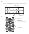
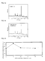
- FIG. 1 is an X-ray diffraction spectrum explaining a difference between a sulfide solid electrolyte material with high ion conductivity and a sulfide solid electrolyte material with low ion conductivity.
- both of the two sulfide solid electrolyte materials in FIG. 1 have a composition of Li 3.25 Ge 0.25 P 0.75 S 4 .
- FIG. 1 is an X-ray diffraction spectrum explaining a difference between a sulfide solid electrolyte material with high ion conductivity and a sulfide solid electrolyte material with low ion conductivity.
- both of the two sulfide solid electrolyte materials in FIG. 1 have a composition of Li 3.25 Ge 0.
- the sulfide solid electrolyte material with low ion conductivity has the same peak.
- this sulfide solid electrolyte material with high ion conductivity has the same crystal structure as the sulfide solid electrolyte material of the first embodiment, as described later.
- Both of the crystal phases A and B are crystal phases exhibiting ion conductivity, which is different.
- the crystal phase A is conceived to be remarkably high in ion conductivity as compared with the crystal phase B.
- a conventional synthesis method (such as a solid-phase method) has not been capable of decreasing the ratio of the crystal phase B with low ion conductivity, and has not been capable of sufficiently heightening ion conductivity.
- the crystal phase A with high ion conductivity may be precipitated so positively as to allow the sulfide solid electrolyte material with high ion conductivity.
- a conventional synthesis method has not allowed the sulfide solid electrolyte material such that a value of I B /I A is less than 0.50.
- the sulfide solid electrolyte material in the first embodiment is preferably high in the ratio of the crystal phase A with high ion conductivity.
- a value of I B /I A is preferably smaller; specifically, preferably 0.45 or less, more preferably 0.25 or less, far more preferably 0.15 or less, and particularly preferably 0.07 or less.
- a value of I B /I A is preferably 0.
- This peak is one of the peaks of the crystal phase A with high ion conductivity, as described above.
- the sulfide solid electrolyte material of the first embodiment comprises an M 1 element, an M 2 element, a S element and an O element.
- the above-mentioned M 1 is not particularly limited if the M 1 contains at least Li, but may be only Li or a combination of Li and another element.
- Another element is, for example, preferably a monovalent or divalent element, specifically, preferably at least one kind selected from the group consisting of Na, K, Mg, Ca and Zn.
- the above-mentioned M 1 may be a monovalent element (such as Li, Na and K), which is partially substituted with a divalent or more element (such as Mg, Ca and Zn).
- a monovalent element moves so easily as to improve ion conductivity.
- the above-mentioned M 2 is preferably a trivalent, tetravalent or pentavalent element.
- the above-mentioned M 2 include one kind selected from the group consisting of P, Sb, Si, Ge, Sn, B, Al, Ga, In, Ti, Zr, V and Nb.
- the above-mentioned M 2 preferably contains at least one kind selected from the group consisting of P, Si, Ge, Al, Zr, Sn and B, and contains at least P and Ge or at least P and Si more preferably.
- the sulfide solid electrolyte material of the first embodiment contains the S element and the O element.
- the ratio of the O element contained in the sulfide solid electrolyte material is preferably a ratio such as to allow higher ion conductivity than ion conductivity of the same sulfide solid electrolyte material except for adjusting valence number with S without containing the O element (a sulfide solid electrolyte material as comparison purpose).
- the sulfide solid electrolyte material as comparison purpose corresponds to Li 3.35 Ge 0 .25P 0.65 S 4 in the case where the sulfide solid electrolyte material of the first embodiment is Li 3.35 Ge 0.35 P 0.65 (S 1-y O y ) 4 , for example.
- the ratio of the O element to the total of the S element and the O element is, for example, preferably 0.1% or more, more preferably 0.5% or more, and far more preferably 1% or more.
- the above-mentioned ratio of the O element is, for example, preferably 25% or less. The reason therefor is to allow the sulfide solid electrolyte material having higher ion conductivity.
- the above-mentioned ratio of the O element may be determined by XPS and EDX, for example.
- an LiGePSO-based sulfide solid electrolyte material is really synthesized and X-ray diffraction measurement of an obtained sample is performed to confirm that I B /I A is a predetermined value or less.
- This LiGePSO-based sulfide solid electrolyte material is such that the M 1 element corresponds to the Li element and the M 2 element corresponds to the Ge element and the P element in the above-mentioned general formula.
- the sulfide solid electrolyte material of the first embodiment ordinarily has a specific crystal structure described in the after-mentioned second embodiment.
- an optional combination of the M 1 element and the M 2 element may offer the same crystal structure as the LiGePSO-based sulfide solid electrolyte material.
- any optional combination of the M 1 element and the M 2 element allows the sulfide solid electrolyte material with favorable ion conductivity.
- a position of a peak in X-ray diffraction depends on a crystal structure, so that it is conceived that a similar XRD pattern is obtained irrespective of kinds of the M 1 element and the M 2 element if the sulfide solid electrolyte material has the above-mentioned crystal structure.
- the sulfide solid electrolyte material of the first embodiment preferably contains at least a Li element, a Ge element, a P element, a S element and an O element.
- the ratio of the O element to the total of the S element and the O element is, for example, preferably 0.1% or more, more preferably 0.5% or more, and far more preferably 1% or more.
- the above-mentioned ratio of O element is, for example, preferably 25% or less.
- the composition of the LiGePSO-based sulfide solid electrolyte material is not particularly limited if the composition is a composition such as to allow a predetermined value of I B /I A , but is preferably a composition of Li (4-x) Ge (1-x) P x (S 1-y O y ) 4 ("x" satisfies 0 ⁇ x ⁇ 1 and "y" satisfies 0 ⁇ y ⁇ 0.25).
- the reason therefor is to allow the sulfide solid electrolyte material with high ion conductivity.
- a composition of Li (4-x) Ge (1-x) P x S 4 not having O element corresponds to a composition of a solid solution of Li 3 PS 4 and Li 4 GeS 4 . That is to say, this composition corresponds to a composition on a tie line of Li 3 PS 4 and Li 4 GeS 4 .
- both Li 3 PS 4 and Li 4 GeS 4 correspond to an ortho-composition and have the advantage that chemical stability is high.
- the sulfide solid electrolyte material having such a composition of Li (4- x) Ge (1-x) P x S 4 has been conventionally known as thio-LISICON, and the sulfide solid electrolyte material of the first embodiment may be identical with conventional thio-LISICON in composition.
- the ratio of a crystal phase contained in the sulfide solid electrolyte material of the first embodiment is entirely different from the ratio of a conventional crystal phase.
- the sulfide solid electrolyte material of the first embodiment has the advantage that ion conductivity is further high by reason of containing theO element.
- x in Li (4-x) Ge (1-x) P x (S 1-y O y ) 4 is not particularly limited if the "x" is a value such as to allow a predetermined value of I B /I A , but satisfies preferably 0.4 ⁇ x, and more preferably 0.5 ⁇ x, for example.
- the above-mentioned x satisfies preferably x ⁇ 0.8, and more preferably x ⁇ 0.75. The reason therefor is that such a range of "x" allows a value of I B /I A to be further decreased.
- the above-mentioned "y" satisfies preferably 0.001 ⁇ y, more preferably 0.005 ⁇ y, and far more preferably 0.01 ⁇ y.
- the above-mentioned y preferably satisfies y ⁇ 0.25.
- the sulfide solid electrolyte material with further favorable ion conductivity may be obtained.
- the sulfide solid electrolyte material of the first embodiment is preferably obtained by using at least Li 2 S, P 2 S 5 and GeS 2 .
- the sulfide solid electrolyte material of the first embodiment preferably contains at least the Li element, the Si element, the P element, the S element and the O element.
- the ratio of the O element to the total of the S element and the O element is, for example, preferably 0.1% or more, more preferably 0.5% or more, and far more preferably 1% or more.
- the above-mentioned ratio of the O element is, for example, preferably 20% or less, more preferably 15% or less, and far more preferably 10% or less.
- the composition of the LiSiPSO-based sulfide solid electrolyte material is not particularly limited if the composition is a composition such as to allow a predetermined value of I B /I A , but is preferably a composition of Li (4-x) Si (1-x) P x (S 1-y O y ) 4 ("x" satisfies 0 ⁇ x ⁇ 1 and y satisfies 0 ⁇ y ⁇ 0.25). The reason therefor is to allow the sulfide solid electrolyte material with high ion conductivity.
- a composition of Li (4-x) Si (1-x) P x S 4 not having O element corresponds to a composition of a solid solution of Li 3 PS 4 and Li 4 SiS 4 . That is to say, this composition corresponds to a composition on a tie line of Li 3 PS 4 and Li 4 SiS 4 .
- both Li 3 PS 4 and Li 4 SiS 4 correspond to an ortho-composition and have the advantage that chemical stability is high.
- x in Li (4-x) Si (1-x) P x (S 1-y O y ) 4 is not particularly limited if the "x" is a value such as to allow a predetermined value of I B /I A , but satisfies preferably 0.4 ⁇ x, and more preferably 0.5 ⁇ x, for example.
- the above-mentioned "x" satisfies preferably x ⁇ 0.8, and more preferably x ⁇ 0.75. The reason therefor is that such a range of "x" allows a value of I B /I A to be further decreased.
- the above-mentioned "y" satisfies preferably 0.001 ⁇ y, more preferably 0.005 ⁇ y, and far more preferably 0.01 ⁇ y.
- the above-mentioned "y” preferably satisfies y ⁇ 0.2, more preferably y ⁇ 0.15, and far more preferably y ⁇ 0.1.
- the sulfide solid electrolyte material of the first embodiment is preferably obtained by using at least Li 2 S, P 2 S 5 and SiS 2 .
- the sulfide solid electrolyte material of the first embodiment is ordinarily a crystalline sulfide solid electrolyte material.
- the sulfide solid electrolyte material of the first embodiment is preferably high in ion conductivity, and ion conductivity of the sulfide solid electrolyte material at 25°C is preferably 1.0 x 10 -3 S/cm or more, and more preferably 2.3 x 10 -3 S/cm or more.
- the shape of the sulfide solid electrolyte material of the first embodiment is not particularly limited but examples thereof include a powdery shape.
- the average particle diameter of the powdery sulfide solid electrolyte material is preferably within a range of 0.1 ⁇ m to 50 ⁇ m, for example.
- the sulfide solid electrolyte material of the first embodiment has so high ion conductivity as to be capable of being used for optional uses in which ion conductivity is required. Above all, the sulfide solid electrolyte material of the first embodiment is preferably used for a battery. The reason therefor is to be capable of greatly contributing to achieving higher output of a battery. Also, a producing method for the sulfide solid electrolyte material of the first embodiment is described in detail in the after-mentioned 'C. Producing method for sulfide solid electrolyte material'. Also, the sulfide solid electrolyte material of the first embodiment may also have characteristics of the after-mentioned second embodiment together.
- the sulfide solid electrolyte material of the second embodiment has an octahedron O composed of an M 1 element and a S element, a tetrahedron T 1 composed of an M 2a element and a S element, and a tetrahedron T 2 composed of an M 2b element and a S element, characterized in that the above-mentioned tetrahedron T 1 and the above-mentioned octahedron O share an edge, the above-mentioned tetrahedron T 2 and the above-mentioned octahedron O contain a crystal structure sharing a corner as the main body, the above-mentioned M 1 contains at least Li, the above-mentioned M 2a and the above-mentioned M 2b are each independently at least one kind selected from the group consisting of P, Sb, Si, Ge, S
- the octahedron O, the tetrahedron T 1 and the tetrahedron T 2 have a predeterimned crystal structure (a three-dimensional structure), so as to allow the sulfide solid electrolyte material with favorable ion conductivity.
- At least one of the octahedron O, the tetrahedron T 1 and the tetrahedron T 2 is such that part of the S element is substituted with the O element, so as to allow the sulfide solid electrolyte material with ion conductivity further improved.
- the use of the sulfide solid electrolyte material of the second embodiment allows a high-output battery.
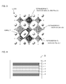
- FIG. 2 is a perspective view explaining an example of a crystal structure of the sulfide solid electrolyte material of the second embodiment.
- the octahedron O has M 1 as the central element, and has six pieces of S (incidentally, part of S may be substituted with O) at the corner of the octahedron; typically, LiS 6-x O x (0 ⁇ x ⁇ 6) octahedron.
- the tetrahedron T 1 has M 2a as the central element, and has four pieces of S (incidentally, part of S may be substituted with O) at the corner of the tetrahedron; typically, both GeS 4-x O x (0 ⁇ x ⁇ 4) tetrahedron and PS 4-x O x (0 ⁇ x ⁇ 4) tetrahedron.
- the tetrahedron T 2 has M 2b as the central element, and has four pieces of S (incidentally, part of S may be substituted with O) at the corner of the tetrahedron; typically, PS 4-x O x (0 ⁇ x ⁇ 4) tetrahedron.
- At least one of the octahedron O, the tetrahedron T 1 and the tetrahedron T 2 is such that part of the S element is substituted with O element.
- the tetrahedron T 1 and the octahedron O share an edge, and the tetrahedron T 2 and the octahedron O share a corner.
- FIG. 3 is a plan view explaining ion conduction in the second embodiment.
- an Li ion conducts in c-axis direction (a vertical direction to the paper plane) through the inside (tunnel T) of the crystal structure composed of the octahedron O, the tetrahedron T 1 and the tetrahedron T 2 .
- an Li ion is disposed somewhat in a zigzag.
- the size of the tunnel T is determined by the size of the corner element and the central element of each of the polyhedrons.
- part of the S element as the corner element of the polyhedrons is substituted with small-sized O element, so that a tunnel size for allowing easy conduction of an Li ion is formed and ion conductivity of the sulfide solid electrolyte material is improved.
- the sulfide solid electrolyte material of the second embodiment is greatly characterized by comprising the above-mentioned crystal structure as the main body.
- the ratio of the above-mentioned crystal structure in the whole crystal structure of the sulfide solid electrolyte material is not particularly limited but is preferably higher. The reason therefor is to allow the sulfide solid electrolyte material with high ion conductivity.
- the ratio of the above-mentioned crystal structure is, specifically, preferably 70 wt% or more, and more preferably 90 wt% or more. Incidentally, the ratio of the above-mentioned crystal structure may be measured by radiated light XRD, for example.
- the sulfide solid electrolyte material of the second embodiment is preferably a single-phase material of the above-mentioned crystal structure. The reason therefor is to allow ion conductivity to be extremely heightened.
- the M 1 element, the M 2 element (the M 2a element and the M 2b element), and other items in the second embodiment are the same as the above-mentioned first embodiment; therefore, the description here is omitted.
- the battery of the present invention is a battery comprising a cathode active material layer containing a cathode active material, an anode active material layer containing an anode active material, and an electrolyte layer formed between the above-mentioned cathode active material layer and the above-mentioned anode active material layer, characterized in that at least one of the above-mentioned cathode active material layer, the above-mentioned anode active material layer and the above-mentioned electrolyte layer contains the above-mentioned sulfide solid electrolyte material.
- the use of the above-mentioned sulfide solid electrolyte material allows the high-output battery.
- FIG. 4 is a schematic cross-sectional view showing an example of the battery of the present invention.
- a battery 10 shown in FIG. 4 comprises a cathode active material layer 1 containing a cathode active material, an anode active material layer 2 containing an anode active material, an electrolyte layer 3 formed between the cathode active material layer 1 and the anode active material layer 2, a cathode current collector 4 for collecting the cathode active material layer 1, an anode current collector 5 for collecting the anode active material layer 2, and a battery case 6 for storing these members.
- At least one of the cathode active material layer 1, the anode active material layer 2 and the electrolyte layer 3 is greatly characterized by containing the sulfide solid electrolyte material described in the above-mentioned 'A. Sulfide solid electrolyte material'.
- the battery of the present invention is hereinafter described in each constitution.
- the electrolyte layer in the present invention is a layer formed between the cathode active material layer and the anode active material layer.
- the electrolyte layer is not particularly limited if the layer is a layer such as to allow ion conduction, but is preferably a solid electrolyte layer composed of a solid electrolyte material. The reason therefor is to allow the battery with high safety as compared with a battery using a liquid electrolyte.
- a solid electrolyte layer preferably contains the above-mentioned sulfide solid electrolyte material.
- the ratio of the above-mentioned sulfide solid electrolyte material contained in a solid electrolyte layer is preferably, for example, within a range of 10% by volume to 100% by volume, above all, within a range of 50% by volume to 100% by volume.
- a solid electrolyte layer is preferably composed of only the above-mentioned sulfide solid electrolyte material. The reason therefor is to allow the high-output battery.
- the thickness of a solid electrolyte layer is preferably within a range of 0.1 ⁇ m to 1000 ⁇ m, for example, and within a range of 0.1 ⁇ m to 300 ⁇ m, above all.
- examples of a method for forming a solid electrolyte layer include a method for compression-molding a solid electrolyte material.
- the electrolyte layer in the present invention may be a layer composed of a liquid electrolyte.
- a liquid electrolyte allows the higher-output battery though safety needs to be further considered as compared with the case of using a solid electrolyte layer.
- at least one of the cathode active material layer and the anode active material layer contains the above-mentioned sulfide solid electrolyte material.
- a liquid electrolyte ordinarily contains a lithium salt and an organic solvent (a nonaqueous solvent).
- lithium salt examples include inorganic lithium salts such as LiPF 6 , LiBF 4 , LiClO 4 and LiAsF 6 , and organic lithium salts such as LiCF 3 SO 3 , LiN(CF 3 SO 2 ) 2 , LiN(C 2 F 5 SO 2 ) 2 and LiC(CF 3 SO 2 ) 3 .
- organic solvent examples include ethylene carbonate (EC), propylene carbonate (PC), dimethyl carbonate (DMC), diethyl carbonate (DEC), ethylmethyl carbonate (EMC) and butylene carbonate (BC).
- the cathode active material layer in the present invention is a layer containing at least a cathode active material, and may contain at least one of a solid electrolyte material, a conductive material and a binder, as required.
- the cathode active material layer contains a solid electrolyte material, which is preferably the above-mentioned sulfide solid electrolyte material. The reason therefor is to allow the cathode active material layer with high ion conductivity.
- the ratio of the above-mentioned sulfide solid electrolyte material contained in the cathode active material layer varies with kinds of a battery and is preferably, for example, within a range of 0.1% by volume to 80% by volume, above all, within a range of 1% by volume to 60% by volume, and particularly, within a range of 10% by volume to 50% by volume.
- examples of a cathode active material include LiCoO 2 , LiMnO 2 , Li 2 NiMn 3 O 8 , LiVO 2 , LiCrO 2 , LiFePO 4 , LiCoPO 4 , LiNiO 2 and LiNi 1/3 Co 1/3 Mn 1/3 O 2 .
- the cathode active material layer in the present invention may further contain a conductive material.
- the addition of the conductive material allows conductivity of the cathode active material layer to be improved.
- the conductive material include acetylene black, Ketjen Black and carbon fiber.
- the cathode active material layer may contain a binder. Examples of kinds of the binder include a fluorine-containing binder such as polytetrafluoroethylene (PTFE).
- the thickness of the cathode active material layer is preferably within a range of 0.1 ⁇ m to 1000 ⁇ m, for example.
- the anode active material layer in the present invention is a layer containing at least an anode active material, and may contain at least one of a solid electrolyte material, a conductive material and a binder, as required.
- the anode active material layer contains a solid electrolyte material, which is preferably the above-mentioned sulfide solid electrolyte material. The reason therefor is to allow the anode active material layer with high ion conductivity.
- the ratio of the above-mentioned sulfide solid electrolyte material contained in the anode active material layer varies with kinds of a battery and is preferably, for example, within a range of 0.1% by volume to 80% by volume, above all, within a range of 1% by volume to 60% by volume, and particularly, within a range of 10% by volume to 50% by volume.
- examples of an anode active material include a metal active material and a carbon active material.
- the metal active material include In, Al, Si, and Sn.
- examples of the carbon active material include mesocarbon microbeads (MCMB), high orientation property graphite (HOPG), hard carbon and soft carbon.
- a conductive material and a binder used for the anode active material layer are the same as the case of the above-mentioned cathode active material layer.
- the thickness of the anode active material layer is preferably within a range of 0.1 ⁇ m to 1000 ⁇ m, for example.
- the battery of the present invention comprises at least the above-mentioned electrolyte layer, cathode active material layer and anode active material layer, ordinarily further comprising a cathode current collector for collecting the cathode active material layer and an anode current collector for collecting the anode active material layer.
- a material for the cathode current collector include SUS, aluminum, nickel, iron, titanium and carbon, and preferably SUS among them.
- examples of a material for the anode current collector include SUS, copper, nickel and carbon, and preferably SUS among them.
- the thickness and shape of the cathode current collector and the anode current collector are preferably selected properly in accordance with factors such as uses of a battery.
- a battery case of a general battery may be used for a battery case used for the present invention. Examples of the battery case include a battery case made of SUS.
- the battery of the present invention may be a primary battery or a secondary battery, and preferably a secondary battery among them.
- the reason therefor is to be repeatedly charged and discharged and be useful as a car-mounted battery, for example.
- Examples of the shape of the battery of the present invention include a coin shape, a laminate shape, a cylindrical shape and a rectangular shape.
- a producing method for the battery of the present invention is not particularly limited if the method is a method such as to allow the above-mentioned battery, but the same method as a producing method for a general battery may be used.
- examples of a producing method therefor include a method such that a material composing a cathode active material layer, a material composing a solid electrolyte layer and a material composing an anode active material layer are sequentially pressed to thereby produce a power generating element and this power generating element is stored inside a battery case, which is crimped.
- the producing method for a sulfide solid electrolyte material of the present invention may be roughly divided into two embodiments. Then, the producing method for a sulfide solid electrolyte material of the present invention is described while divided into a first embodiment and a second embodiment.
- the producing method for the sulfide solid electrolyte material of the first embodiment is a producing method for the sulfide solid electrolyte material described in 'A.
- First embodiment' comprising steps of: an ion conductive material synthesizing step of synthesizing an amorphized ion conductive material by mechanical milling while using a raw material composition containing the above-mentioned M 1 element, the above-mentioned M 2 element, the above-mentioned S element and the above-mentioned O element, and a heating step of obtaining the above-mentioned sulfide solid electrolyte material by heating the above-mentioned amorphized ion conductive material.
- the sulfide solid electrolyte material with favorable ion conductivity may be obtained.
- the inclusion of the O element in the raw material composition allows the sulfide solid electrolyte material with ion conductivity further improved.
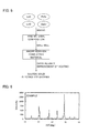
- FIG. 5 is an explanatory view showing an example of the producing method for the sulfide solid electrolyte material of the first embodiment.
- a raw material composition is produced by mixing Li 2 S, Li 2 O, P 2 S 5 and GeS 2 .
- the raw material composition is preferably produced under an inert gas atmosphere.
- ball mill is performed for the raw material composition to obtain an amorphized ion conductive material.
- the amorphized ion conductive material is heated for improving crystallinity to thereby obtain a sulfide solid electrolyte material.
- the amorphized ion conductive material is once synthesized unlike a solid-phase method as a conventional synthesis method.
- the producing method for the sulfide solid electrolyte material of the first embodiment is hereinafter described in each step.
- the ion conductive material synthesizing step in the first embodiment is a step of synthesizing an amorphized ion conductive material by mechanical milling while using a raw material composition containing the above-mentioned M 1 element, the above-mentioned M 2 element, the above-mentioned S element and the above-mentioned O element.
- the raw material composition in the first embodiment is not particularly limited if the raw material composition is such as to contain the M 1 element, the M 2 element, the S element and the O element.
- the M 1 element and the M 2 element in the raw material composition are the same as the items described in the above-mentioned 'A.
- Sulfide solid electrolyte material' A compound containing the M 1 element is not particularly limited but examples thereof include a simple substance of M 1 and a sulfide of M 1 .
- Examples of the sulfide of M 1 include Li 2 S, Na 2 S, K 2 S, MgS, CaS and ZnS.
- a compound containing M 2 element is not particularly limited but examples thereof include a simple substance of M 2 and a sulfide of M 2 .
- the sulfide of M 2 include Me 2 S 3 (Me is a trivalent element such as Al, B, Ga, In and Sb), MeS 2 (Me is a tetravalent element such as Ge, Si, Sn, Zr, Ti and Nb) and Me 2 S 5 (Me is a pentavalent element such as P and V).
- a compound containing the S element is not particularly limited but may be a simple substance or a sulfide.
- the sulfide include a sulfide containing the above-mentioned M 1 element or M 2 element.
- a compound containing the O element is ordinarily an oxide.
- kinds of the oxide are not particularly limited but are preferably an oxide containing the above-mentioned M 1 element or M 2 element. The reason therefor is not to produce an unnecessary side reaction.
- Examples of the above-mentioned oxide include Me 2 O 3 (Me is a trivalent element such as Al, B, Ga, In and Sb), MeO 2 (Me is a tetravalent element such as Ge, Si, Sn, Zr, Ti and Nb), Me 2 O 5 (Me is a pentavalent element such as P and V), Li 5 MeO 4 (Me is a trivalent element such as Al, B, Ga, In and Sb), Li 4 MeO 4 (Me is a tetravalent element such as Ge, Si, Sn, Zr, Ti and Nb) and Li 3 MeO 4 (Me is a pentavalent element such as P and V).
- the raw material composition preferably has a composition of Li (4-x) Ge (1-x) P x (S 1-y O y ) 4 ("x" satisfies 0 ⁇ x ⁇ 1 and "y" satisfies 0 ⁇ y ⁇ 0.25).
- the reason therefor is to allow the sulfide solid electrolyte material with high ion conductivity.
- a composition of Li (4-x) Ge (1-x) P x S 4 not having O element corresponds to a composition of a solid solution of Li 3 PS 4 and Li 4 GeS 4 .
- the used amount of Li 2 S, P 2 S 5 and GeS 2 is preferably determined in consideration of these ratios.
- a preferable range of "x" and "y” is the same as the contents described in the above-mentioned 'A. Sulfide solid electrolyte material'.
- the raw material composition preferably has a composition of Li (4-x) Si (1-x) P x (S 1-y O y ) 4 ("x" satisfies 0 ⁇ x ⁇ 1 and "y" satisfies 0 ⁇ y ⁇ 0.25).
- the reason therefor is to allow the sulfide solid electrolyte material with high ion conductivity.
- a composition of Li (4-x) Si (1-x) P x S 4 not having O element corresponds to a composition of a solid solution of Li 3 PS 4 and Li 4 SiS 4 .
- the used amount of Li 2 S, P 2 S 5 and SiS 2 is preferably determined in consideration of these ratios.
- a preferable range of "x" and "y” is the same as the contents described in the above-mentioned 'A. Sulfide solid electrolyte material'.
- Mechanical milling is a method for grinding a test sample while allowing mechanical energy thereto.
- an amorphized ion conductive material is synthesized by allowing mechanical energy to the raw material composition.
- Examples of such mechanical milling include vibrating mill, ball mill, turbo mill, mechano-fusion and disk mill; and among them, preferably vibrating mill and ball mill.
- the conditions of vibrating mill are not particularly limited if the conditions are such as to allow an amorphized ion conductive material.
- the vibration amplitude of vibrating mill is preferably, for example, within a range of 5 mm to 15 mm, and above all, within a range of 6 mm to 10 mm.
- the vibration frequency of vibrating mill is preferably, for example, within a range of 500 rpm to 2000 rpm, and above all, within a range of 1000 rpm to 1800 rpm.
- the filling factor of a test sample of vibrating mill is preferably, for example, within a range of 1% by volume to 80% by volume, and above all, within a range of 5% by volume to 60% by volume, and particularly, within a range of 10% by volume to 50% by volume.
- a vibrator (such as a vibrator made of alumina) is preferably used for vibrating mill.
- the conditions of ball mill are not particularly limited if the conditions are such as to allow an amorphized ion conductive material. Generally, larger number of revolutions brings higher production rate of the ion conductive material, and longer treating time brings higher conversion ratio of the raw material composition into the ion conductive material.
- the number of weighing table revolutions in performing planetary ball mill is preferably within a range of 200 rpm to 500 rpm, for example, and within a range of 250 rpm to 400 rpm, above all.
- the treating time in performing planetary ball mill is preferably within a range of 1 hour to 100 hours, for example, and within a range of 1 hour to 70 hours, above all.
- a heating step in the first embodiment is a step of obtaining the above-mentioned sulfide solid electrolyte material by heating the above-mentioned amorphized ion conductive material.
- the above-mentioned heating temperature is preferably 300°C or more, more preferably 350°C or more, far more preferably 400°C or more, and particularly preferably 450°C or more.
- the above-mentioned heating temperature is preferably 1000°C or less, more preferably 700°C or less, far more preferably 650°C or less, and particularly preferably 600°C or less.
- the heating time is preferably adjusted properly so as to allow a desired sulfide solid electrolyte material.
- heating in the first embodiment is preferably performed under an inert gas atmosphere or in a vacuum from the viewpoint of preventing oxidation.
- the sulfide solid electrolyte material obtained by the first embodiment is the same as the contents described in the above-mentioned 'A. Sulfide solid electrolyte material 1. First embodiment'; therefore, the description here is omitted.
- the producing method for the sulfide solid electrolyte material of the second embodiment is a producing method for the sulfide solid electrolyte material described in 'A.
- Second embodiment' comprising steps of: an ion conductive material synthesizing step of synthesizing an amorphized ion conductive material by mechanical milling while using a raw material composition containing the above-mentioned M 1 element, the above-mentioned M 2a element, the above-mentioned M 2b element, the above-mentioned S element and the above-mentioned O element, and a heating step of obtaining the above-mentioned sulfide solid electrolyte material by heating the above-mentioned amorphized ion conductive material.
- amorphization is performed in the ion conductive material synthesizing step to thereafter perform the heating step, so as to allow the sulfide solid electrolyte material such that the octahedron O, the tetrahedron T 1 and the tetrahedron T 2 have a predeterimned crystal structure (a three-dimensional structure).
- the sulfide solid electrolyte material with favorable ion conductivity may be obtained.
- the inclusion of the O element in the raw material composition allows the sulfide solid electrolyte material with ion conductivity further improved.
- the ion conductive material synthesizing step and the heating step in the second embodiment are basically the same as the contents described in the above-mentioned 'C.
- Various kinds of conditions are preferably determined so as to allow a desired sulfide solid electrolyte material.
- the present invention is not limited to the above-mentioned embodiments.
- the above-mentioned embodiments are exemplification, and any is included in the technical scope of the present invention if it has substantially the same constitution as the technical idea described in the claim of the present invention and offers similar operation and effect thereto.
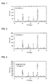
- Lithium sulfide (Li 2 S), lithium oxide (Li 2 O), phosphorus pentasulfide (P 2 S 5 ) and germanium sulfide (GeS 2 ) were used as a starting material. These powders were mixed in a glove box under an argon atmosphere at a ratio of 0.3495 g of Li 2 S, 0.03082 g of Li 2 O, 0.372641 g of P 2 S 5 and 0.2469 g of GeS 2 to obtain a raw material composition. The obtained raw material composition was ground by using vibrating mill. TI-100 TM manufactured by Cosmic Mechanical Technology Co., Ltd. was used for vibrating mill.
- the obtained ion conductive material was molded into pellets, and the obtained pellets were put in a carbon-coated quartz tube and vacuum-sealed.
- the pressure of the quartz tube for vacuum-sealing was approximately 30 Pa.
- the quartz tube was placed in a burning furnace, heated from room temperature to 550°C over 6 hours, maintained at 550°C for 8 hours, and thereafter slowly cooled up to room temperature.
- a crystalline sulfide solid electrolyte material having a composition of Li 3.35 Ge 0.35 P 0.65 (S 0.95 O 0.05 ) 4 was obtained.
- the oxygen amount substituted is 5%.
- a crystalline sulfide solid electrolyte material was obtained in the same manner as Example 1 except for using a mixture at a ratio of 0.30728 g of Li 2 S, 0.06269 g of Li 2 O, 0.378922 g of P 2 S 5 and 0.251096 g of GeS 2 as a raw material composition.
- the oxygen amount substituted is 10%.
- a crystalline sulfide solid electrolyte material was obtained in the same manner as Example 1 except for using a mixture at a ratio of 0.190304 g of Li 2 S, 0.150803 g of Li 2 O, 0.3962890 g of P 2 S 5 and 0.262604 g of GeS 2 as a raw material composition.
- the oxygen amount substituted is 23%.
- a crystalline sulfide solid electrolyte material was obtained in the same manner as Example 1 except for using a mixture at a ratio of 0.390529 g of Li 2 S, 0.366564 g of P 2 S 5 and 0.242907 g of GeS 2 as a raw material composition.
- the oxygen amount substituted is 0%.
- these peaks are conceived to be the peaks of the crystal phase A with high ion conductivity.
- FIGS. 6 to 8 it was confirmed that Examples 1 to 3 had the same diffraction pattern as Comparative Example 1.
- the crystal structure of the sulfide solid electrolyte material obtained in Comparative Example 1 was identified by X-ray structural analysis.
- the crystal system and crystallographic group were determined by a direct method on the basis of a diffraction pattern obtained in XRD to thereafter identify the crystal structure by a real space method.
- the sulfide solid electrolyte material had the above-mentioned crystal structure as shown in FIGS. 2 and 3 .
- the crystal structure was such that the tetrahedron T 1 (GeS 4 tetrahedron and PS 4 tetrahedron) and the octahedron O (LiS 6 octahedron) shared an edge, and the tetrahedron T 2 (PS 4 tetrahedron) and the octahedron O (LiS 6 octahedron) shared a corner. Also, as described above, Examples 1 to 3 had the same diffraction pattern as Comparative Example 1, so that it was confirmed that the same crystal structure was formed in Examples 1 to 3.
- Li ion conductance at a temperature of 25°C was measured while using the sulfide solid electrolyte material obtained in Examples 1 to 3 and Comparative Example 1.
- a test sample was weighed by a suitable amount in a glove box of an argon atmosphere, put in a polyethylene terephthalate tube (a PET tube, an inside diameter of 10 mm, an outside diameter of 30 mm, a height of 20 mm), and held between powder molding jigs made of carbon tool steel S45C anvil from the top and bottom.
- a polyethylene terephthalate tube a PET tube, an inside diameter of 10 mm, an outside diameter of 30 mm, a height of 20 mm
- the test sample was pressed at an indicating pressure of 6 MPa (a molding pressure of approximately 110 MPa) by using a uniaxial pressing machine (P-6 TM manufactured by Rikenseiki Co., Ltd.), and molded into pellets with a diameter of 10 mm and an optional thickness.
- gold powder manufactured by The Nilaco Corporation, treelike, a particle diameter of approximately 10 ⁇ m
- the obtained pellets were put in a closed electrochemical cell which may maintain an argon atmosphere.
- An impedance gain-phase analyzer manufactured by Solartron Inc. (solartron 1260 TM ) was used for the measurement as FRA (Frequency Response Analyzer), and a small-sized environmental tester (Espec corp, SU-241 TM , - 40°C to 150°C) was used as a constant temperature unit.
- the measurement was started from a high-frequency range on the conditions of an alternating voltage of 10 mV to 1000 mV, a frequency range of 1 Hz to 10 MHz, an integration time of 0.2 second, and a temperature of 23°C.
- Zplot TM was used for measurement software and Zview TM was used for analysis software. The obtained results are shown in FIG. 10 .
- Li ion conductance was high in Examples 1 to 3 such that sulfur was substituted with oxygen as compared with Comparative Example 1 such that sulfur was not substituted with oxygen.
- the reason why Li ion conductance of the sulfide solid electrolyte material obtained in Examples 1 to 3 is high is conceived to be that the introduction of the O element causes the size of a tunnel through which an Li ion passes (a tunnel existing in a crystal) to change into a size for allowing easier conduction.
- Lithium sulfide (Li 2 S, manufactured by Nippon Chemical Industrial Co., Ltd.), lithium oxide (Li 2 O, manufactured by Kojundo Chemical Lab. Co., Ltd.), phosphorus pentasulfide (P 2 S 5 , manufactured by Sigma-Aldrich Co. LLC.) and silicon sulfide (SiS 2 , manufactured by Kojundo Chemical Lab. Co., Ltd.) were used as a starting material.
- These powders were mixed in a glove box under an argon atmosphere at a ratio of 0.34083 g of Li 2 S, 0.06819 g of Li 2 O, 0.38049 g of P 2 S 5 and 0.21047 g of SiS 2 to obtain a raw material composition.
- the oxygen amount substituted is 10%.
- a crystalline sulfide solid electrolyte material was obtained in the same manner as Example 4 except for using a mixture at a ratio of 0.386186 g of Li 2 S, 0.03348565 g of Li 2 O, 0.373641747 g of P 2 S 5 and 0.2066865 g of SiS 2 as a raw material composition.
- the oxygen amount substituted is 5%.
- a crystalline sulfide solid electrolyte material was obtained in the same manner as Example 4 except for using a mixture at a ratio of 0.2449428 g of Li 2 S, 0.141591 g of Li 2 O, 0.3949774 g of P 2 S 5 and 0.21848871 g of SiS 2 as a raw material composition.
- the oxygen amount substituted is 20%.
- a crystalline sulfide solid electrolyte material was obtained in the same manner as Example 4 except for using a mixture at a ratio of 0.429936 g of Li 2 S, 0.367033 g of P 2 S 5 and 0.203030 g of SiS 2 as a raw material composition.
- the oxygen amount substituted is 0%.
- X-ray diffraction (XRD) measurement was performed while using the sulfide solid electrolyte material obtained in Examples 4 to 6 and Comparative Example 2. XRD measurement was performed for a powder sample under an inert atmosphere on the conditions of using a CuK ⁇ ray. The results are shown in FIGS. 11 to 14 . As shown in FIGS. 11 to 14 , it was confirmed that Examples 4 to 6 and Comparative Example 2 had the same diffraction pattern as the above-mentioned Comparative Example 1.
- Li ion conductance at a temperature of 25°C was measured while using the sulfide solid electrolyte material obtained in Examples 4 to 6 and Comparative Example 2.
- the measuring method is the same as the method described in Evaluations 1.
- the obtained results are shown in FIG. 15 .
- FIG. 15 it was confirmed that Li ion conductance was equal or high in Examples 4 to 6 such that sulfur was substituted with oxygen as compared with Comparative Example 2 such that sulfur was not substituted with oxygen.
- Li ion conductance of the sulfide solid electrolyte material obtained in Examples 1 to 3 is high is conceived to be that the introduction of the O element causes the size of a tunnel through which an Li ion passes (a tunnel existing in a crystal) to change into a size for allowing easier conduction.
Landscapes
- Chemical & Material Sciences (AREA)
- Organic Chemistry (AREA)
- Engineering & Computer Science (AREA)
- Chemical Kinetics & Catalysis (AREA)
- Electrochemistry (AREA)
- General Chemical & Material Sciences (AREA)
- Inorganic Chemistry (AREA)
- Manufacturing & Machinery (AREA)
- Physics & Mathematics (AREA)
- Condensed Matter Physics & Semiconductors (AREA)
- General Physics & Mathematics (AREA)
- Materials Engineering (AREA)
- Secondary Cells (AREA)
- Conductive Materials (AREA)
- Battery Electrode And Active Subsutance (AREA)
Applications Claiming Priority (3)
| Application Number | Priority Date | Filing Date | Title |
|---|---|---|---|
| JP2011281179 | 2011-12-22 | ||
| JP2012234153A JP5888610B2 (ja) | 2011-12-22 | 2012-10-23 | 硫化物固体電解質材料、電池および硫化物固体電解質材料の製造方法 |
| PCT/JP2012/083350 WO2013094757A1 (fr) | 2011-12-22 | 2012-12-21 | Matériau d'électrolyte solide à base de sulfure, batterie, et procédé de production d'un matériau d'électrolyte solide à base de sulfure |
Publications (3)
| Publication Number | Publication Date |
|---|---|
| EP2797152A1 true EP2797152A1 (fr) | 2014-10-29 |
| EP2797152A4 EP2797152A4 (fr) | 2015-08-05 |
| EP2797152B1 EP2797152B1 (fr) | 2019-01-23 |
Family
ID=48668634
Family Applications (1)
| Application Number | Title | Priority Date | Filing Date |
|---|---|---|---|
| EP12860207.5A Active EP2797152B1 (fr) | 2011-12-22 | 2012-12-21 | Matériau d'électrolyte solide à base de sulfure, batterie, et procédé de production d'un matériau d'électrolyte solide à base de sulfure |
Country Status (6)
| Country | Link |
|---|---|
| US (1) | US9263763B2 (fr) |
| EP (1) | EP2797152B1 (fr) |
| JP (1) | JP5888610B2 (fr) |
| KR (1) | KR101667468B1 (fr) |
| CN (1) | CN103999279B (fr) |
| WO (1) | WO2013094757A1 (fr) |
Cited By (1)
| Publication number | Priority date | Publication date | Assignee | Title |
|---|---|---|---|---|
| EP3018660A4 (fr) * | 2013-07-04 | 2016-11-30 | Mitsui Mining & Smelting Co | Électrolyte solide cristallin et son procédé de fabrication |
Families Citing this family (37)
| Publication number | Priority date | Publication date | Assignee | Title |
|---|---|---|---|---|
| WO2014171483A1 (fr) | 2013-04-16 | 2014-10-23 | トヨタ自動車株式会社 | Matériau d'électrolyte solide à base de sulfure, pile, et procédé de fabrication d'un matériau d'électrolyte solide à base de sulfure |
| CN105518906B (zh) | 2013-05-15 | 2019-04-16 | 量子世界公司 | 用于使用LiAMPBSC的电池的固态阴极电解质或电解质(M=Si、Ge和/或Sn) |
| CN105453324B (zh) | 2013-06-07 | 2018-09-04 | 丰田自动车株式会社 | 硫化物固体电解质材料、电池和硫化物固体电解质材料的制造方法 |
| US9761861B1 (en) | 2013-06-25 | 2017-09-12 | Quantumscape Corporation | Pulse plating of lithium material in electrochemical devices |
| JP5720753B2 (ja) | 2013-10-02 | 2015-05-20 | トヨタ自動車株式会社 | 硫化物固体電解質材料、電池および硫化物固体電解質材料の製造方法 |
| JP6213340B2 (ja) * | 2014-03-27 | 2017-10-18 | 株式会社村田製作所 | 固体電解質及び全固体電池 |
| KR20230164760A (ko) | 2014-06-04 | 2023-12-04 | 퀀텀스케이프 배터리, 인코포레이티드 | 혼합 입자 크기를 가진 전극 물질 |
| JP6288716B2 (ja) | 2014-06-25 | 2018-03-07 | 国立大学法人東京工業大学 | 硫化物固体電解質材料の製造方法 |
| JP5975071B2 (ja) * | 2014-07-22 | 2016-08-23 | トヨタ自動車株式会社 | 硫化物固体電解質材料、電池および硫化物固体電解質材料の製造方法 |
| WO2016126610A1 (fr) | 2015-02-03 | 2016-08-11 | Quantumscape Corporation | Anolytes en sulfure métallique pour cellules électrochimiques |
| JP6222134B2 (ja) * | 2015-02-25 | 2017-11-01 | トヨタ自動車株式会社 | 硫化物固体電解質材料、電池および硫化物固体電解質材料の製造方法 |
| CN114388879A (zh) | 2015-06-24 | 2022-04-22 | 昆腾斯科普电池公司 | 复合电解质 |
| CN107683510B (zh) * | 2015-07-02 | 2019-09-24 | 国立大学法人东京工业大学 | 硫化物固体电解质材料、电池和硫化物固体电解质材料的制造方法 |
| JP6877084B2 (ja) * | 2015-07-31 | 2021-05-26 | 国立大学法人東京工業大学 | α−リチウム固体電解質 |
| JP2017045613A (ja) * | 2015-08-26 | 2017-03-02 | 出光興産株式会社 | 硫化物固体電解質及びその製造方法 |
| US10116001B2 (en) | 2015-12-04 | 2018-10-30 | Quantumscape Corporation | Lithium, phosphorus, sulfur, and iodine including electrolyte and catholyte compositions, electrolyte membranes for electrochemical devices, and annealing methods of making these electrolytes and catholytes |
| JP6881892B2 (ja) * | 2015-12-25 | 2021-06-02 | 三星電子株式会社Samsung Electronics Co.,Ltd. | 固体電解質、全固体電池及び固体電解質の製造方法 |
| US11245131B2 (en) | 2015-12-25 | 2022-02-08 | Samsung Electronics Co., Ltd. | Solid electrolyte and lithium battery including the same |
| JP7049665B2 (ja) * | 2016-08-22 | 2022-04-07 | 公立大学法人大阪 | 全固体二次電池用の複合正極活物質、その製造方法、正極及び全固体二次電池 |
| KR102448921B1 (ko) * | 2016-08-23 | 2022-09-30 | 고쿠리츠다이가쿠호진 토쿄고교 다이가꾸 | 황화물 고체전해질 |
| US11342630B2 (en) | 2016-08-29 | 2022-05-24 | Quantumscape Battery, Inc. | Catholytes for solid state rechargeable batteries, battery architectures suitable for use with these catholytes, and methods of making and using the same |
| US11735780B2 (en) | 2017-03-10 | 2023-08-22 | Quantumscape Battery, Inc. | Metal negative electrode ultrasonic charging |
| CN108695549B (zh) * | 2017-03-31 | 2021-07-16 | 国立大学法人东京工业大学 | 固体电解质材料及其制造方法 |
| JP6986467B2 (ja) * | 2017-03-31 | 2021-12-22 | 国立大学法人東京工業大学 | 固体電解質材料およびその製造方法 |
| JP7236648B2 (ja) * | 2017-09-08 | 2023-03-10 | パナソニックIpマネジメント株式会社 | 硫化物固体電解質材料及びそれを用いた電池 |
| KR101952196B1 (ko) * | 2017-11-29 | 2019-02-26 | 전자부품연구원 | 고체 전해질, 그 제조 방법 및 이를 포함하는 전고체 전지 |
| CN108258303B (zh) * | 2018-01-18 | 2020-05-22 | 中国科学院宁波材料技术与工程研究所 | 一种硫化物固体电解质、其制备方法及全固态锂二次电池 |
| CN108390094B (zh) * | 2018-02-06 | 2020-10-30 | 华中科技大学 | 一种空气稳定硫化物钠离子固体电解质及其制备方法 |
| JP6870779B2 (ja) | 2018-02-14 | 2021-05-12 | 株式会社村田製作所 | 共振装置及び共振装置製造方法 |
| US11127974B2 (en) | 2018-05-14 | 2021-09-21 | Samsung Electronics Co., Ltd. | Method of preparing sulfide-based solid electrolyte, sulfide-based solid electrolyte prepared therefrom, and solid secondary battery including the sulfide electrolyte |
| US11799126B2 (en) | 2019-05-31 | 2023-10-24 | Samsung Electronics Co., Ltd. | Method of preparing solid electrolyte and all-solid battery including solid electrolyte prepared by the method |
| WO2021049415A1 (fr) * | 2019-09-11 | 2021-03-18 | 三井金属鉱業株式会社 | Électrolyte solide au sulfure |
| CN110718713B (zh) * | 2019-12-02 | 2022-08-02 | 天目湖先进储能技术研究院有限公司 | 一种含卤素晶体硫化物固态电解质规模化制备方法 |
| JP6861869B2 (ja) * | 2020-04-07 | 2021-04-21 | 国立大学法人東京工業大学 | α−リチウム固体電解質 |
| CN112777632B (zh) * | 2021-01-25 | 2022-05-03 | 武汉船用电力推进装置研究所(中国船舶重工集团公司第七一二研究所) | 一种硫化物锂离子固态电解质及其制备方法和应用 |
| CN113471521B (zh) * | 2021-06-30 | 2022-08-19 | 国联汽车动力电池研究院有限责任公司 | 一种无机硫化物固体电解质及其制备方法 |
| CN113937351B (zh) * | 2021-10-08 | 2023-09-22 | 武汉船用电力推进装置研究所(中国船舶重工集团公司第七一二研究所) | 一种硫银锗矿型硫化物锂离子固态电解质及其制备方法和应用 |
Family Cites Families (12)
| Publication number | Priority date | Publication date | Assignee | Title |
|---|---|---|---|---|
| JP4498688B2 (ja) * | 2003-04-24 | 2010-07-07 | 出光興産株式会社 | リチウムイオン伝導性硫化物ガラス及びガラスセラミックスの製造方法 |
| JP4813767B2 (ja) * | 2004-02-12 | 2011-11-09 | 出光興産株式会社 | リチウムイオン伝導性硫化物系結晶化ガラス及びその製造方法 |
| JP4754209B2 (ja) * | 2004-12-16 | 2011-08-24 | 日本化学工業株式会社 | リチウムコバルト系複合酸化物粉末の製造方法 |
| JP4165536B2 (ja) | 2005-06-28 | 2008-10-15 | 住友電気工業株式会社 | リチウム二次電池負極部材およびその製造方法 |
| JP4996120B2 (ja) * | 2006-03-31 | 2012-08-08 | 出光興産株式会社 | 固体電解質、その製造方法及び全固体二次電池 |
| JP4834442B2 (ja) * | 2006-03-31 | 2011-12-14 | 出光興産株式会社 | 固体電解質、その製造方法及び全固体二次電池 |
| JP4392618B2 (ja) * | 2006-05-15 | 2010-01-06 | 住友電気工業株式会社 | 固体電解質の形成方法 |
| US20110171398A1 (en) * | 2010-01-12 | 2011-07-14 | Oladeji Isaiah O | Apparatus and method for depositing alkali metals |
| KR20110055635A (ko) * | 2008-10-03 | 2011-05-25 | 도요타지도샤가부시키가이샤 | 전고체형 리튬 전지의 제조 방법 |
| JP5590836B2 (ja) * | 2009-09-09 | 2014-09-17 | 公立大学法人大阪府立大学 | 硫化物固体電解質 |
| CN102823049B (zh) | 2010-03-26 | 2015-04-01 | 国立大学法人东京工业大学 | 硫化物固体电解质材料、电池和硫化物固体电解质材料的制造方法 |
| JP2012089424A (ja) * | 2010-10-21 | 2012-05-10 | Sumitomo Electric Ind Ltd | 固体電解質および非水電解質電池 |
-
2012
- 2012-10-23 JP JP2012234153A patent/JP5888610B2/ja active Active
- 2012-12-21 WO PCT/JP2012/083350 patent/WO2013094757A1/fr active Application Filing
- 2012-12-21 KR KR1020147016378A patent/KR101667468B1/ko active IP Right Grant
- 2012-12-21 EP EP12860207.5A patent/EP2797152B1/fr active Active
- 2012-12-21 US US14/365,950 patent/US9263763B2/en active Active
- 2012-12-21 CN CN201280061858.8A patent/CN103999279B/zh active Active
Cited By (1)
| Publication number | Priority date | Publication date | Assignee | Title |
|---|---|---|---|---|
| EP3018660A4 (fr) * | 2013-07-04 | 2016-11-30 | Mitsui Mining & Smelting Co | Électrolyte solide cristallin et son procédé de fabrication |
Also Published As
| Publication number | Publication date |
|---|---|
| EP2797152B1 (fr) | 2019-01-23 |
| KR20140103957A (ko) | 2014-08-27 |
| US9263763B2 (en) | 2016-02-16 |
| CN103999279B (zh) | 2017-05-31 |
| JP2013149599A (ja) | 2013-08-01 |
| WO2013094757A1 (fr) | 2013-06-27 |
| JP5888610B2 (ja) | 2016-03-22 |
| KR101667468B1 (ko) | 2016-10-18 |
| US20140363745A1 (en) | 2014-12-11 |
| CN103999279A (zh) | 2014-08-20 |
| EP2797152A4 (fr) | 2015-08-05 |
Similar Documents
| Publication | Publication Date | Title |
|---|---|---|
| US9263763B2 (en) | Sulfide solid electrolyte material, battery, and producing method for sulfide solid electrolyte material | |
| US10033065B2 (en) | Sulfide solid electrolyte material, battery, and producing method for sulfide solid electrolyte material | |
| US10388985B2 (en) | Sulfide solid electrolyte material, battery, and producing method for sulfide solid electrolyte material | |
| US9929433B2 (en) | Sulfide solid electrolyte material, battery, and producing method for sulfide solid electrolyte material | |
| US8697292B2 (en) | Sulfide solid electrolyte material, battery, and method for producing sulfide solid electrolyte material | |
| US9748603B2 (en) | Sulfide solid electrolyte material, battery, and producing method for sulfide solid electrolyte material | |
| US10128532B2 (en) | Sulfide solid electrolyte material, battery, and method for producing sulfide solid electrolyte material | |
| US20160248119A1 (en) | Sulfide solid electrolyte material, battery, and method for producing sulfide solid electrolyte material | |
| US10355308B2 (en) | Sulfide solid electrolyte material, battery, and producing method for sulfide solid electrolyte material | |
| US9748602B2 (en) | Sulfide solid electrolyte material, battery, and producing method for sulfide solid electrolyte material | |
| CN118099511A (zh) | 硫化物固体电解质材料及其制造方法、和使用其的电池 |
Legal Events
| Date | Code | Title | Description |
|---|---|---|---|
| PUAI | Public reference made under article 153(3) epc to a published international application that has entered the european phase |
Free format text: ORIGINAL CODE: 0009012 |
|
| 17P | Request for examination filed |
Effective date: 20140618 |
|
| AK | Designated contracting states |
Kind code of ref document: A1 Designated state(s): AL AT BE BG CH CY CZ DE DK EE ES FI FR GB GR HR HU IE IS IT LI LT LU LV MC MK MT NL NO PL PT RO RS SE SI SK SM TR |
|
| DAX | Request for extension of the european patent (deleted) | ||
| RA4 | Supplementary search report drawn up and despatched (corrected) |
Effective date: 20150708 |
|
| RIC1 | Information provided on ipc code assigned before grant |
Ipc: C01B 25/16 20060101ALI20150702BHEP Ipc: H01M 6/18 20060101ALI20150702BHEP Ipc: H01M 10/052 20100101ALI20150702BHEP Ipc: H01B 1/06 20060101ALI20150702BHEP Ipc: H01M 4/06 20060101ALI20150702BHEP Ipc: H01M 10/0562 20100101AFI20150702BHEP Ipc: H01M 4/62 20060101ALI20150702BHEP Ipc: H01B 13/00 20060101ALI20150702BHEP Ipc: H01B 1/10 20060101ALI20150702BHEP Ipc: H01M 4/13 20100101ALI20150702BHEP |
|
| GRAP | Despatch of communication of intention to grant a patent |
Free format text: ORIGINAL CODE: EPIDOSNIGR1 |
|
| STAA | Information on the status of an ep patent application or granted ep patent |
Free format text: STATUS: GRANT OF PATENT IS INTENDED |
|
| RIC1 | Information provided on ipc code assigned before grant |
Ipc: H01B 1/10 20060101ALI20180420BHEP Ipc: H01M 6/18 20060101ALI20180420BHEP Ipc: H01M 4/13 20100101ALI20180420BHEP Ipc: C01G 17/00 20060101ALI20180420BHEP Ipc: H01M 10/052 20100101ALI20180420BHEP Ipc: H01M 10/0562 20100101AFI20180420BHEP Ipc: H01M 4/62 20060101ALI20180420BHEP Ipc: C01B 17/20 20060101ALI20180420BHEP Ipc: H01M 4/06 20060101ALI20180420BHEP |
|
| INTG | Intention to grant announced |
Effective date: 20180529 |
|
| GRAS | Grant fee paid |
Free format text: ORIGINAL CODE: EPIDOSNIGR3 |
|
| GRAA | (expected) grant |
Free format text: ORIGINAL CODE: 0009210 |
|
| STAA | Information on the status of an ep patent application or granted ep patent |
Free format text: STATUS: THE PATENT HAS BEEN GRANTED |
|
| AK | Designated contracting states |
Kind code of ref document: B1 Designated state(s): AL AT BE BG CH CY CZ DE DK EE ES FI FR GB GR HR HU IE IS IT LI LT LU LV MC MK MT NL NO PL PT RO RS SE SI SK SM TR |
|
| REG | Reference to a national code |
Ref country code: GB Ref legal event code: FG4D |
|
| REG | Reference to a national code |
Ref country code: CH Ref legal event code: EP |
|
| REG | Reference to a national code |
Ref country code: AT Ref legal event code: REF Ref document number: 1092175 Country of ref document: AT Kind code of ref document: T Effective date: 20190215 |
|
| REG | Reference to a national code |
Ref country code: IE Ref legal event code: FG4D |
|
| REG | Reference to a national code |
Ref country code: DE Ref legal event code: R096 Ref document number: 602012056344 Country of ref document: DE |
|
| REG | Reference to a national code |
Ref country code: NL Ref legal event code: MP Effective date: 20190123 |
|
| PG25 | Lapsed in a contracting state [announced via postgrant information from national office to epo] |
Ref country code: NL Free format text: LAPSE BECAUSE OF FAILURE TO SUBMIT A TRANSLATION OF THE DESCRIPTION OR TO PAY THE FEE WITHIN THE PRESCRIBED TIME-LIMIT Effective date: 20190123 |
|
| PG25 | Lapsed in a contracting state [announced via postgrant information from national office to epo] |
Ref country code: ES Free format text: LAPSE BECAUSE OF FAILURE TO SUBMIT A TRANSLATION OF THE DESCRIPTION OR TO PAY THE FEE WITHIN THE PRESCRIBED TIME-LIMIT Effective date: 20190123 Ref country code: NO Free format text: LAPSE BECAUSE OF FAILURE TO SUBMIT A TRANSLATION OF THE DESCRIPTION OR TO PAY THE FEE WITHIN THE PRESCRIBED TIME-LIMIT Effective date: 20190423 Ref country code: PT Free format text: LAPSE BECAUSE OF FAILURE TO SUBMIT A TRANSLATION OF THE DESCRIPTION OR TO PAY THE FEE WITHIN THE PRESCRIBED TIME-LIMIT Effective date: 20190523 Ref country code: SE Free format text: LAPSE BECAUSE OF FAILURE TO SUBMIT A TRANSLATION OF THE DESCRIPTION OR TO PAY THE FEE WITHIN THE PRESCRIBED TIME-LIMIT Effective date: 20190123 Ref country code: LT Free format text: LAPSE BECAUSE OF FAILURE TO SUBMIT A TRANSLATION OF THE DESCRIPTION OR TO PAY THE FEE WITHIN THE PRESCRIBED TIME-LIMIT Effective date: 20190123 Ref country code: FI Free format text: LAPSE BECAUSE OF FAILURE TO SUBMIT A TRANSLATION OF THE DESCRIPTION OR TO PAY THE FEE WITHIN THE PRESCRIBED TIME-LIMIT Effective date: 20190123 Ref country code: PL Free format text: LAPSE BECAUSE OF FAILURE TO SUBMIT A TRANSLATION OF THE DESCRIPTION OR TO PAY THE FEE WITHIN THE PRESCRIBED TIME-LIMIT Effective date: 20190123 |
|
| REG | Reference to a national code |
Ref country code: AT Ref legal event code: MK05 Ref document number: 1092175 Country of ref document: AT Kind code of ref document: T Effective date: 20190123 |
|
| PG25 | Lapsed in a contracting state [announced via postgrant information from national office to epo] |
Ref country code: GR Free format text: LAPSE BECAUSE OF FAILURE TO SUBMIT A TRANSLATION OF THE DESCRIPTION OR TO PAY THE FEE WITHIN THE PRESCRIBED TIME-LIMIT Effective date: 20190424 Ref country code: BG Free format text: LAPSE BECAUSE OF FAILURE TO SUBMIT A TRANSLATION OF THE DESCRIPTION OR TO PAY THE FEE WITHIN THE PRESCRIBED TIME-LIMIT Effective date: 20190423 Ref country code: IS Free format text: LAPSE BECAUSE OF FAILURE TO SUBMIT A TRANSLATION OF THE DESCRIPTION OR TO PAY THE FEE WITHIN THE PRESCRIBED TIME-LIMIT Effective date: 20190523 Ref country code: HR Free format text: LAPSE BECAUSE OF FAILURE TO SUBMIT A TRANSLATION OF THE DESCRIPTION OR TO PAY THE FEE WITHIN THE PRESCRIBED TIME-LIMIT Effective date: 20190123 Ref country code: RS Free format text: LAPSE BECAUSE OF FAILURE TO SUBMIT A TRANSLATION OF THE DESCRIPTION OR TO PAY THE FEE WITHIN THE PRESCRIBED TIME-LIMIT Effective date: 20190123 Ref country code: LV Free format text: LAPSE BECAUSE OF FAILURE TO SUBMIT A TRANSLATION OF THE DESCRIPTION OR TO PAY THE FEE WITHIN THE PRESCRIBED TIME-LIMIT Effective date: 20190123 |
|
| REG | Reference to a national code |
Ref country code: DE Ref legal event code: R097 Ref document number: 602012056344 Country of ref document: DE |
|
| PG25 | Lapsed in a contracting state [announced via postgrant information from national office to epo] |
Ref country code: SK Free format text: LAPSE BECAUSE OF FAILURE TO SUBMIT A TRANSLATION OF THE DESCRIPTION OR TO PAY THE FEE WITHIN THE PRESCRIBED TIME-LIMIT Effective date: 20190123 Ref country code: CZ Free format text: LAPSE BECAUSE OF FAILURE TO SUBMIT A TRANSLATION OF THE DESCRIPTION OR TO PAY THE FEE WITHIN THE PRESCRIBED TIME-LIMIT Effective date: 20190123 Ref country code: RO Free format text: LAPSE BECAUSE OF FAILURE TO SUBMIT A TRANSLATION OF THE DESCRIPTION OR TO PAY THE FEE WITHIN THE PRESCRIBED TIME-LIMIT Effective date: 20190123 Ref country code: EE Free format text: LAPSE BECAUSE OF FAILURE TO SUBMIT A TRANSLATION OF THE DESCRIPTION OR TO PAY THE FEE WITHIN THE PRESCRIBED TIME-LIMIT Effective date: 20190123 Ref country code: DK Free format text: LAPSE BECAUSE OF FAILURE TO SUBMIT A TRANSLATION OF THE DESCRIPTION OR TO PAY THE FEE WITHIN THE PRESCRIBED TIME-LIMIT Effective date: 20190123 Ref country code: IT Free format text: LAPSE BECAUSE OF FAILURE TO SUBMIT A TRANSLATION OF THE DESCRIPTION OR TO PAY THE FEE WITHIN THE PRESCRIBED TIME-LIMIT Effective date: 20190123 Ref country code: AL Free format text: LAPSE BECAUSE OF FAILURE TO SUBMIT A TRANSLATION OF THE DESCRIPTION OR TO PAY THE FEE WITHIN THE PRESCRIBED TIME-LIMIT Effective date: 20190123 |
|
| PG25 | Lapsed in a contracting state [announced via postgrant information from national office to epo] |
Ref country code: SM Free format text: LAPSE BECAUSE OF FAILURE TO SUBMIT A TRANSLATION OF THE DESCRIPTION OR TO PAY THE FEE WITHIN THE PRESCRIBED TIME-LIMIT Effective date: 20190123 |
|
| PLBE | No opposition filed within time limit |
Free format text: ORIGINAL CODE: 0009261 |
|
| STAA | Information on the status of an ep patent application or granted ep patent |
Free format text: STATUS: NO OPPOSITION FILED WITHIN TIME LIMIT |
|
| PG25 | Lapsed in a contracting state [announced via postgrant information from national office to epo] |
Ref country code: AT Free format text: LAPSE BECAUSE OF FAILURE TO SUBMIT A TRANSLATION OF THE DESCRIPTION OR TO PAY THE FEE WITHIN THE PRESCRIBED TIME-LIMIT Effective date: 20190123 |
|
| 26N | No opposition filed |
Effective date: 20191024 |
|
| PG25 | Lapsed in a contracting state [announced via postgrant information from national office to epo] |
Ref country code: SI Free format text: LAPSE BECAUSE OF FAILURE TO SUBMIT A TRANSLATION OF THE DESCRIPTION OR TO PAY THE FEE WITHIN THE PRESCRIBED TIME-LIMIT Effective date: 20190123 |
|
| REG | Reference to a national code |
Ref country code: DE Ref legal event code: R084 Ref document number: 602012056344 Country of ref document: DE |
|
| PG25 | Lapsed in a contracting state [announced via postgrant information from national office to epo] |
Ref country code: TR Free format text: LAPSE BECAUSE OF FAILURE TO SUBMIT A TRANSLATION OF THE DESCRIPTION OR TO PAY THE FEE WITHIN THE PRESCRIBED TIME-LIMIT Effective date: 20190123 |
|
| REG | Reference to a national code |
Ref country code: GB Ref legal event code: 746 Effective date: 20200414 |
|
| REG | Reference to a national code |
Ref country code: CH Ref legal event code: PL |
|
| REG | Reference to a national code |
Ref country code: BE Ref legal event code: MM Effective date: 20191231 |
|
| PG25 | Lapsed in a contracting state [announced via postgrant information from national office to epo] |
Ref country code: MC Free format text: LAPSE BECAUSE OF FAILURE TO SUBMIT A TRANSLATION OF THE DESCRIPTION OR TO PAY THE FEE WITHIN THE PRESCRIBED TIME-LIMIT Effective date: 20190123 |
|
| PG25 | Lapsed in a contracting state [announced via postgrant information from national office to epo] |
Ref country code: IE Free format text: LAPSE BECAUSE OF NON-PAYMENT OF DUE FEES Effective date: 20191221 Ref country code: LU Free format text: LAPSE BECAUSE OF NON-PAYMENT OF DUE FEES Effective date: 20191221 |
|
| PG25 | Lapsed in a contracting state [announced via postgrant information from national office to epo] |
Ref country code: LI Free format text: LAPSE BECAUSE OF NON-PAYMENT OF DUE FEES Effective date: 20191231 Ref country code: CH Free format text: LAPSE BECAUSE OF NON-PAYMENT OF DUE FEES Effective date: 20191231 Ref country code: BE Free format text: LAPSE BECAUSE OF NON-PAYMENT OF DUE FEES Effective date: 20191231 |
|
| PG25 | Lapsed in a contracting state [announced via postgrant information from national office to epo] |
Ref country code: CY Free format text: LAPSE BECAUSE OF FAILURE TO SUBMIT A TRANSLATION OF THE DESCRIPTION OR TO PAY THE FEE WITHIN THE PRESCRIBED TIME-LIMIT Effective date: 20190123 |
|
| PG25 | Lapsed in a contracting state [announced via postgrant information from national office to epo] |
Ref country code: HU Free format text: LAPSE BECAUSE OF FAILURE TO SUBMIT A TRANSLATION OF THE DESCRIPTION OR TO PAY THE FEE WITHIN THE PRESCRIBED TIME-LIMIT; INVALID AB INITIO Effective date: 20121221 Ref country code: MT Free format text: LAPSE BECAUSE OF FAILURE TO SUBMIT A TRANSLATION OF THE DESCRIPTION OR TO PAY THE FEE WITHIN THE PRESCRIBED TIME-LIMIT Effective date: 20190123 |
|
| PG25 | Lapsed in a contracting state [announced via postgrant information from national office to epo] |
Ref country code: MK Free format text: LAPSE BECAUSE OF FAILURE TO SUBMIT A TRANSLATION OF THE DESCRIPTION OR TO PAY THE FEE WITHIN THE PRESCRIBED TIME-LIMIT Effective date: 20190123 |
|
| PGFP | Annual fee paid to national office [announced via postgrant information from national office to epo] |
Ref country code: GB Payment date: 20231102 Year of fee payment: 12 |
|
| PGFP | Annual fee paid to national office [announced via postgrant information from national office to epo] |
Ref country code: FR Payment date: 20231108 Year of fee payment: 12 Ref country code: DE Payment date: 20231031 Year of fee payment: 12 |