EP2788568B1 - Aussenverriegelungsmodul für ein schloss - Google Patents
Aussenverriegelungsmodul für ein schloss Download PDFInfo
- Publication number
- EP2788568B1 EP2788568B1 EP12837630.8A EP12837630A EP2788568B1 EP 2788568 B1 EP2788568 B1 EP 2788568B1 EP 12837630 A EP12837630 A EP 12837630A EP 2788568 B1 EP2788568 B1 EP 2788568B1
- Authority
- EP
- European Patent Office
- Prior art keywords
- transmission lever
- housing
- switching nut
- lock
- nut
- Prior art date
- Legal status (The legal status is an assumption and is not a legal conclusion. Google has not performed a legal analysis and makes no representation as to the accuracy of the status listed.)
- Active
Links
Images


Classifications
-
- E—FIXED CONSTRUCTIONS
- E05—LOCKS; KEYS; WINDOW OR DOOR FITTINGS; SAFES
- E05B—LOCKS; ACCESSORIES THEREFOR; HANDCUFFS
- E05B85/00—Details of vehicle locks not provided for in groups E05B77/00 - E05B83/00
- E05B85/06—Lock cylinder arrangements
-
- E—FIXED CONSTRUCTIONS
- E05—LOCKS; KEYS; WINDOW OR DOOR FITTINGS; SAFES
- E05B—LOCKS; ACCESSORIES THEREFOR; HANDCUFFS
- E05B15/00—Other details of locks; Parts for engagement by bolts of fastening devices
- E05B15/004—Lost motion connections
-
- E—FIXED CONSTRUCTIONS
- E05—LOCKS; KEYS; WINDOW OR DOOR FITTINGS; SAFES
- E05B—LOCKS; ACCESSORIES THEREFOR; HANDCUFFS
- E05B17/00—Accessories in connection with locks
- E05B17/04—Devices for coupling the turning cylinder of a single or a double cylinder lock with the bolt operating member
- E05B17/041—Coupling device with a shaft projecting axially rearwardly from the cylinder, e.g. affording a degree of universal motion to compensate for misalignment
-
- E—FIXED CONSTRUCTIONS
- E05—LOCKS; KEYS; WINDOW OR DOOR FITTINGS; SAFES
- E05B—LOCKS; ACCESSORIES THEREFOR; HANDCUFFS
- E05B17/00—Accessories in connection with locks
- E05B17/04—Devices for coupling the turning cylinder of a single or a double cylinder lock with the bolt operating member
- E05B17/047—Devices for coupling the turning cylinder of a single or a double cylinder lock with the bolt operating member with rotating output elements forming part of cylinder locks, e.g. locking cams of double cylinder locks
-
- E—FIXED CONSTRUCTIONS
- E05—LOCKS; KEYS; WINDOW OR DOOR FITTINGS; SAFES
- E05B—LOCKS; ACCESSORIES THEREFOR; HANDCUFFS
- E05B63/00—Locks or fastenings with special structural characteristics
- E05B63/0017—Locks with sliding bolt without provision for latching
-
- E—FIXED CONSTRUCTIONS
- E05—LOCKS; KEYS; WINDOW OR DOOR FITTINGS; SAFES
- E05B—LOCKS; ACCESSORIES THEREFOR; HANDCUFFS
- E05B85/00—Details of vehicle locks not provided for in groups E05B77/00 - E05B83/00
- E05B85/02—Lock casings
-
- Y—GENERAL TAGGING OF NEW TECHNOLOGICAL DEVELOPMENTS; GENERAL TAGGING OF CROSS-SECTIONAL TECHNOLOGIES SPANNING OVER SEVERAL SECTIONS OF THE IPC; TECHNICAL SUBJECTS COVERED BY FORMER USPC CROSS-REFERENCE ART COLLECTIONS [XRACs] AND DIGESTS
- Y10—TECHNICAL SUBJECTS COVERED BY FORMER USPC
- Y10T—TECHNICAL SUBJECTS COVERED BY FORMER US CLASSIFICATION
- Y10T70/00—Locks
- Y10T70/70—Operating mechanism
- Y10T70/7441—Key
- Y10T70/7486—Single key
Definitions
- the invention relates to a locking module for locking a lock for a motor vehicle, comprising a housing, a sliding nut, which can be connected to a lock cylinder for turning the Wegnuss by a key, and with a mechanism for converting a rotational movement of the sliding nut into a a linear movement of a driver for locking and unlocking the lock, wherein the Wegnuss is rotatably supported by the housing, wherein further a transmission lever for transmitting the rotational movement of the Wegnuss is provided on the driver, and wherein the transmission lever rotatably supported by the housing and against a displacement is secured along its axis of rotation.
- a lock for a motor vehicle or a building has a locking mechanism, which comprises a pivotable rotary latch and at least one pivotable pawl for locking the rotary latch.
- a locking mechanism which comprises a pivotable rotary latch and at least one pivotable pawl for locking the rotary latch.
- Such a lock is used for temporary closing of openings in motor vehicles or buildings by means of doors or flaps.
- the rotary latch engages around the usually bow-shaped locking bolt - also called lock holder - around - which is usually attached to the body in the case of a motor vehicle.
- the catch Reached the catch by pivoting, starting from an open position, a closed position, the catch is finally locked by means of the pawl. Then the catch can not be rotated back in the direction of the open position and the locking bolt will not leave the locking mechanism.
- For opening it is necessary to move the pawl out of the detent position.
- Such a lock is regularly connected via a mechanism with a lock cylinder and handle.
- a latched catch can be unlatched to open an associated door or flap.
- a door or flap can be locked by a locking module so that it can not be opened by pressing the handle.
- Module in the sense of the invention means that the inclusion of at least the sliding nut is accommodated in a single or multi-part separate housing. Separate housing in turn means that the door lock can be mounted on the module, at least one further housing part.
- a closed door or flap must first be unlocked to reopen the door or flap afterwards.
- the locking module is used to transmit a rotary movement of a key to a mechanism that prevents in the closed state, the locking mechanism by pressing the handle unlocked and the door or flap can then be opened.
- the publication DE 101 52 618 A1 discloses a lock for a motor vehicle with lock cylinder and handle.
- a locking cylinder located in an outer handle is connected via a rod to a key rotor.
- a rotary movement of a key is transmitted through the lock cylinder to the key rotor.
- a corresponding rotational movement of the key rotor is transmitted to a lever mechanism which causes the unlocking or locking of a vehicle door by turning.
- Using a rod an operation of the outer handle can be transferred to the locking mechanism for unlocking.
- the invention is based on the technical problem to further develop such a locking module that a simple production with a high reliability and at the same time small space available.
- a backlash between the transmission lever and the shift nut is present, which is able to delay a movement of the shift nut transmitted to the driver, wherein the axis of rotation of the Wegnuss and the axis of rotation of the transmission lever a Include angles smaller than 180 °.
- the transmission lever for securing against displacement on an annular circumferential groove on the outside of its lateral surface, in which extends a suitably projecting portion of the housing.
- the mechanism comprises the driver, which is moved linearly by a rotational movement of the shift nut. If, in the installed state of the locking module, the sliding nut is thus turned by a key by turning a locking cylinder connected to the sliding nut, this rotational movement is converted by the mechanism into a linear movement of the driver transformed. The linear movement in turn actuates a mechanism in the installed state of the locking module, which causes the unlocking or unlocking or locking or locking the lock.
- the shift nut is rotatably supported by the housing.
- a bearing is provided by the housing, which receives the Wennnuss and causes the rotatable mounting of the shift nut.
- the number of parts is kept small to provide a locking module. This keeps the technical production effort low and at the same time brings the advantage of a high reliability.
- the reliability is ensured in particular by the fact that the Wennnuss is received circumferentially in the housing.
- the mechanism comprises the transmission lever which transmits a movement of the shift nut to the driver.
- the transmission lever is such that a rotational movement of the Wegnuss causes a rotation of the transmission lever.
- the transmission lever is also connected to the driver so that a rotation of the transmission lever causes a linear movement of the driver.
- the transmission lever advantageously makes it possible to provide additional functions and / or special configurations.
- an in particular cylindrical or conical lateral surface of the sliding nut extends at least partially into a cylindrical or conical circumferential surface in particular.
- a stop On the outer circumference of the lateral surface of the shift nut is then a stop which can be moved by turning the switch nut against a stop which is located on the inner circumference of the lateral surface of the transmission lever. If the stopper of the sliding nut has been moved by turning the sliding nut against the stop of the transmission lever, an additional turning of the operating handle causes a rotational movement of the transmission lever. As long as the stop of the shift nut has not been moved against the stop of the transmission lever by turning the control nut, the transmission lever does not rotate together with the control nut. It is thus provided a backlash between the shift nut and transmission lever.
- this backlash can be realized by the lateral surface of the transmission lever in the lateral surface of the Wegnuss extends at least partially. Then there is a stop on the outside of the lateral surface of the transmission lever and a stop on the inside of the lateral surface of the sliding nut.
- Such a backlash is in one embodiment at least 20 °, preferably at least 25 °. It is necessary in this embodiment, the Wegnuss by at least 20 °, preferably at least 25 ° to rotate before a transmission lever is rotated with. It is thus particularly reliably avoided that accidentally turning a key inadvertently locks or unlocks a lock.
- a backlash is in this case defined by the fact that the lock cylinder or key to a insertion position, that is, a zero position, is rotatable in positive and negative directions, without a movement, in particular a moment to effect from the shift nut on the transmission lever and / or the driver ,
- the axes of rotation of the sliding nut and the transmission lever are arranged at an angle to one another which is smaller than 180 °.
- This arrangement of the transmission lever relative to the shift nut serves to convert a rotational movement of the shift nut in a linear movement of the driver in a desired direction, since the selection of the angle affects the direction of movement of the driver.
- the module can be adapted particularly easily to different installation situations in this embodiment.
- the transmission lever is rotatably supported by the housing so as to keep the number of parts and thus the manufacturing cost low.
- the driver is slidably supported by the housing so as to keep the number of parts and thus the manufacturing cost low.
- a spring is provided which, following a rotational movement of the shift nut, moves a component of the locking module which is movable by the sliding nut back into an intermediate position, in particular the transmission lever. It can be provided as a neutral position for the transmission lever as soon as no or at least no excessively high force acts on the transmission lever. In this way, it can be reliably ensured that an idle movement between the shift nut and the transmission lever also remains if the shift nut is turned back by a key following unlocking or locking in order to remove the key from the lock cylinder, in the insertion position or zero position of the lock cylinder can.
- the FIG. 1 shows a module for locking a lock, in which one half of a housing 1 is removed to release the view into the interior of the module.
- the FIG. 2 shows a part of the FIG. 1 , but without a sliding nut 2.
- a shift nut 2 is rotatably mounted.
- the lateral surface of the sliding nut 2 has an outwardly ring-like projecting portion 3, which extends into an annular groove 4 of the housing 1 into it.
- Groove 4 and projecting area 3 contribute to the fact that the sliding nut 2 on the one hand rotatably supported by the housing 1 and on the other hand is secured against displacement.
- Such a designed reception of the shift nut serves the functional safety.
- the Wegnuss 2 may be provided with an annular groove on its outer surface into which a protruding ring of the housing 1 extends, on the one hand rotatably support the Wegnuss and on the other hand to secure against displacement.
- the shift nut 2 in an embodiment of the invention, at least one annular or other rotationally symmetrical region 5 of the lateral surface of the sliding nut 2, which in one embodiment adjacent to the projecting portion 3 and which is rotatably supported, for example, by two inner sides 6 of the housing 1.
- This rotatably mounted end portion of the sliding nut 2 can be connected by an adjacent opening in the housing 1, for example, with a rod, not shown, or be, which in turn is connected to a lock cylinder of a door or flap.
- the connection of the rod with the Wegnuss 2 can be provided by positive engagement, adhesion and / or material bond.
- a turning of the lock cylinder by means of a key is due to the rod or an equivalent component on the sliding nut 2, which is rotated for locking or unlocking a corresponding lock accordingly.
- the lateral surface of the sliding nut 2 tapers conically in one embodiment towards an end, to which a transmission lever 7 is adjacent.
- This taper preferably takes place starting from the end region that can be connected to a rod, in particular starting from the protruding region 3 in the direction of the transmission lever 7.
- An end region of this taper extends into an opening 8 of the transmission lever 7.
- the transmission lever 7 is in turn rotatably supported or held by the housing 1.
- the transmission lever 7 is secured by the housing 1 against displacement along its axis of rotation.
- the transmission lever 7 for securing against displacement on an annular circumferential groove 9 on the outside of its lateral surface into which a suitably projecting portion 10 of the housing 1 extends. Adjacent to the groove 9 areas are advantageous rotationally symmetric and are rotatably supported by respective housing surfaces or stored to stabilize the storage. Since the Heidelbergnuss 2 extends with a tapered end in the transmission lever 7, it is possible to arrange the axis of rotation of the Heidelbergnuss 2 at an angle not equal to 180 ° relative to the axis of rotation of the transmission lever 7. That is, the Heidelbergnuss 2 and the transmission lever 7 can not be aligned parallel to each other. This makes it possible to flexibly adapt the module by selecting a suitable angle between the two axis of rotation to geometric requirements, in for example a motor vehicle door.
- the transmission lever 7 has a lever arm 11 which is movably connected to a driver 12, preferably with an end portion.
- the driver 12 is preferably mounted displaceably by the housing 1.
- the connection between the lever 11 and the driver 12 is such that a pivoting of the lever 11 causes a displacement of the driver 12.
- the driver 12 may be L-shaped for this purpose.
- the short end is then connected to the free end of the lever 11 for displacing the driver 12 pivoting the transmission lever 7.
- the connection between the lever 11 and the driver 12 preferably includes a game to move the driver 12 particularly reliable and easy by pivoting the lever 11, which is pivoted by a sufficient rotation of the sliding nut 2
- the transfer lever 7 has two stops 13 and 14 on the inner periphery of its opening 8. A stop on the outer periphery of the shift nut 2 can be moved between these two stops 13 and 14 back and forth. In this way, a backlash between the shift 2 and transmission lever 7 is provided.
- the distance between the both stops 13 and 14 are chosen so that the stop of the sliding nut 2 can be rotated from a central position by up to + 25 ° or -25 °, without the transmission lever is rotated. Only at rotations greater than 25 ° then reaches the stop of the sliding nut 2 a corresponding stop 13 or 14 of the transmission lever 7, so that subsequently the transmission lever 7 is.
- the housing 1 comprises a further shell, with the in the Figures 1 and 2 shown housing shell can be connected so that the shift nut 2, transmission lever 7 are completely or at least almost completely in the housing 1.
- the driver 12 is basically only partially in the housing 1. Its reaching out of the housing 1 end is connected to a mechanism, not shown, with which the associated lock, also not shown, can be locked or unlocked.
- a receiving unit 15 may be provided, which provides one or more areas for receiving electrical components and / or which is provided with one or more electrical conductor tracks.
- the receiving unit 15 is preferably held and secured in a form-fitting manner in order to minimize the number of parts and to keep the production costs low.
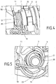
- the reaching out of the housing 1 out end of the driver 12 can, as in the FIG. 3 shown having a slot 16 which serves that an internal operation of a lock from the interior of a motor vehicle can act independently of its external operation.
- the slot could also be omitted, but then would be moved at an opening of the door by means of the internal operation of the driver and the transmission lever, which in turn would result in a heavier actuation. It would have overcome more friction and it would have to be moved more components.
- a second, in this embodiment, independent housing shell of the housing 1 is shown.
- the module may comprise a leg spring 17, which ensures that the transmission lever 7 is moved back to a middle position after pivoting.
- the leg spring 17 may be held by a shaft 20 of the transmission lever 7.
- the two legs 18 and 19 of the leg spring 17 are on the one hand on the housing 1 on one side so that they can be deflected by a corresponding pivoting of the transmission lever 7 by means of a partially circular projecting element 21 of the transmission lever 7 and in particular against a bias of the spring 17th
- the spring 17 ensures that the transmission lever 7 in the in the FIG. 5 shown position, that is insertion or zero position, is turned back.
Landscapes
- Lock And Its Accessories (AREA)
Applications Claiming Priority (2)
| Application Number | Priority Date | Filing Date | Title |
|---|---|---|---|
| DE201110120885 DE102011120885A1 (de) | 2011-12-09 | 2011-12-09 | Außenverriegelungsmodul für ein Schloss |
| PCT/DE2012/001179 WO2013083115A2 (de) | 2011-12-09 | 2012-12-06 | Aussenverriegelungsmodul für ein schloss |
Publications (2)
| Publication Number | Publication Date |
|---|---|
| EP2788568A2 EP2788568A2 (de) | 2014-10-15 |
| EP2788568B1 true EP2788568B1 (de) | 2016-05-18 |
Family
ID=48013678
Family Applications (1)
| Application Number | Title | Priority Date | Filing Date |
|---|---|---|---|
| EP12837630.8A Active EP2788568B1 (de) | 2011-12-09 | 2012-12-06 | Aussenverriegelungsmodul für ein schloss |
Country Status (11)
Families Citing this family (1)
| Publication number | Priority date | Publication date | Assignee | Title |
|---|---|---|---|---|
| CN108193956B (zh) * | 2016-12-08 | 2019-09-10 | 开开特股份公司 | 机动车门锁 |
Family Cites Families (19)
| Publication number | Priority date | Publication date | Assignee | Title |
|---|---|---|---|---|
| US2605631A (en) | 1949-09-03 | 1952-08-05 | Briggs & Stratton Corp | Pillar lock |
| DE3626925A1 (de) | 1986-08-08 | 1988-02-18 | Daimler Benz Ag | Lenkradverriegelung fuer kraftwagen |
| JPH07166740A (ja) * | 1993-12-16 | 1995-06-27 | Yuhshin Co Ltd | シリンダ錠のレバー組付構造 |
| JP3545646B2 (ja) * | 1999-06-11 | 2004-07-21 | 株式会社アルファ | ロック装置 |
| DE10017439A1 (de) | 2000-04-07 | 2001-10-11 | Bayerische Motoren Werke Ag | Schlossanordnung insbesondere für eine Kraftfahrzeugtür oder-klappe |
| JP3777968B2 (ja) | 2000-10-26 | 2006-05-24 | アイシン精機株式会社 | ドアロック装置 |
| DE10135265A1 (de) * | 2001-07-19 | 2003-02-06 | Huf Huelsbeck & Fuerst Gmbh | Schließvorrichtung |
| DE10230586B4 (de) * | 2002-07-05 | 2005-12-15 | Kiekert Ag | Kraftfahrzeugtürverschluss |
| JP4279519B2 (ja) * | 2002-07-19 | 2009-06-17 | 株式会社森創 | 施錠装置 |
| IL156153A (en) | 2003-05-27 | 2009-06-15 | Eyal Artsiely | Multifunctional vehicle lock |
| FR2895762A1 (fr) * | 2005-12-30 | 2007-07-06 | Valeo Securite Habitacle Sas | Verrou debrayable pour un mecanisme de serrure automobile |
| DE102007063349A1 (de) * | 2007-12-28 | 2009-07-02 | Kiekert Ag | Kraftfahrzeugtürverschluss |
| DE102008032585B4 (de) * | 2008-07-11 | 2018-07-19 | Huf Hülsbeck & Fürst Gmbh & Co. Kg | Vorrichtung zur Ansteuerung eines Sperrgliedes |
| JP5030908B2 (ja) | 2008-09-16 | 2012-09-19 | 株式会社ホンダロック | 車両のドア開閉装置 |
| DE102008048772A1 (de) * | 2008-09-24 | 2010-03-25 | Kiekert Ag | Kraftfahrzeugtürverschluss |
| GB2474846A (en) * | 2009-10-27 | 2011-05-04 | Arvinmeritor Light Vehicle Sys | Latch system comprising key barrel operably coupled to latch via a clutch mechanism |
| US20110179834A1 (en) | 2010-01-25 | 2011-07-28 | ACCO Brands Corporation | Security apparatus including breakaway key |
| US8534099B2 (en) * | 2010-07-01 | 2013-09-17 | Adams Rite Manufacturing Co. | Single and multi-point door lock |
| DE102011107877A1 (de) * | 2011-07-18 | 2013-01-24 | Kiekert Ag | Schloss für eine Fahrzeugtür mit Federblech im Einlaufbereich des Schließbolzens |
-
2011
- 2011-12-09 DE DE201110120885 patent/DE102011120885A1/de not_active Withdrawn
-
2012
- 2012-12-06 EP EP12837630.8A patent/EP2788568B1/de active Active
- 2012-12-06 BR BR112014013534A patent/BR112014013534A2/pt not_active Application Discontinuation
- 2012-12-06 MX MX2014006649A patent/MX2014006649A/es not_active Application Discontinuation
- 2012-12-06 WO PCT/DE2012/001179 patent/WO2013083115A2/de active Application Filing
- 2012-12-06 CA CA2858241A patent/CA2858241A1/en not_active Abandoned
- 2012-12-06 KR KR1020147016513A patent/KR102083626B1/ko active Active
- 2012-12-06 JP JP2014545097A patent/JP6142381B2/ja active Active
- 2012-12-06 CN CN201280060294.6A patent/CN103975114B/zh active Active
- 2012-12-06 RU RU2014121745A patent/RU2621391C2/ru not_active IP Right Cessation
- 2012-12-06 US US14/363,910 patent/US9482037B2/en active Active
Non-Patent Citations (1)
| Title |
|---|
| None * |
Also Published As
| Publication number | Publication date |
|---|---|
| US20140352373A1 (en) | 2014-12-04 |
| CN103975114B (zh) | 2017-04-26 |
| JP6142381B2 (ja) | 2017-06-07 |
| KR102083626B1 (ko) | 2020-03-02 |
| CN103975114A (zh) | 2014-08-06 |
| BR112014013534A2 (pt) | 2017-06-13 |
| MX2014006649A (es) | 2014-09-08 |
| EP2788568A2 (de) | 2014-10-15 |
| RU2621391C2 (ru) | 2017-06-05 |
| WO2013083115A3 (de) | 2013-09-26 |
| RU2014121745A (ru) | 2016-01-27 |
| US9482037B2 (en) | 2016-11-01 |
| KR20140106570A (ko) | 2014-09-03 |
| JP2015505923A (ja) | 2015-02-26 |
| DE102011120885A1 (de) | 2013-06-13 |
| CA2858241A1 (en) | 2013-06-13 |
| WO2013083115A2 (de) | 2013-06-13 |
Similar Documents
| Publication | Publication Date | Title |
|---|---|---|
| EP2920020B1 (de) | Verriegelungsvorrichtung zum verriegeln von elektrischen steckern | |
| DE102007044088B4 (de) | Binär codierter Schlüssel und manipulationssicheres Schloss | |
| EP0722029B1 (de) | Kraftfahrzeug-Türschloss mit rotorischer Zentralverriegelung | |
| EP2098743B1 (de) | Stellmechanismus zum Ein- und Ausrücken einer Trennkupplung mit drehbarem Kurvensegment | |
| EP2106488B1 (de) | Drehspannverschluss mit betätigungsgriffsicherung | |
| EP3784855B1 (de) | Kraftfahrzeugschloss | |
| WO2017103175A1 (de) | SCHLIEßEINRICHTUNG FÜR EINE TÜR, TÜRANORDNUNG | |
| EP3812541B1 (de) | Kraftfahrzeug-schloss, insbesondere fahrzeug-heckklappenschloss | |
| EP3269904B1 (de) | Kupplungssystem für ein schloss | |
| DE102007011554B4 (de) | Koppeleinheit für elektronische Schließ-Systeme | |
| EP1079127B1 (de) | Zahnkupplung für kettengetriebene Fahrzeuge | |
| EP2788568B1 (de) | Aussenverriegelungsmodul für ein schloss | |
| EP3847328B1 (de) | Antriebseinheit für kraftfahrzeugtechnische anwendungen | |
| WO2019008054A1 (de) | Verriegelungsvorrichtung sowie lenksäulenbaugruppe | |
| DE10042191B4 (de) | Kraftfahrzeug-Türschloß mit gesteuertem Stellelement | |
| WO2020249165A1 (de) | Hebelanordnung für kraftfahrzeugtechnische anwendungen | |
| WO2017129158A1 (de) | Schwenkriegelschloss | |
| WO2016055052A1 (de) | Kraftfahrzeugtürverschluss und verfahren zur montage eines kraftfahrzeugtürverschlussis | |
| DE102014219341A1 (de) | Parksperrenanordnung | |
| DE19526660B4 (de) | Elektromechanisches Schloß | |
| DE102012107144B4 (de) | Kraftfahrzeugtürverschluss | |
| EP3204581B1 (de) | Kraftfahrzeugtürverschluss | |
| DE4407912A1 (de) | Elektromechanisches Schloß | |
| EP3768542B1 (de) | Stellantrieb für ein kraftfahrzeug-klappenelement | |
| DE102010030018A1 (de) | Drehbeschlag mit integrierter Bremsvorrichtung |
Legal Events
| Date | Code | Title | Description |
|---|---|---|---|
| PUAI | Public reference made under article 153(3) epc to a published international application that has entered the european phase |
Free format text: ORIGINAL CODE: 0009012 |
|
| 17P | Request for examination filed |
Effective date: 20140605 |
|
| AK | Designated contracting states |
Kind code of ref document: A2 Designated state(s): AL AT BE BG CH CY CZ DE DK EE ES FI FR GB GR HR HU IE IS IT LI LT LU LV MC MK MT NL NO PL PT RO RS SE SI SK SM TR |
|
| DAX | Request for extension of the european patent (deleted) | ||
| 17Q | First examination report despatched |
Effective date: 20150709 |
|
| RIC1 | Information provided on ipc code assigned before grant |
Ipc: E05B 15/00 20060101AFI20151125BHEP Ipc: E05B 85/06 20140101ALI20151125BHEP Ipc: E05B 17/04 20060101ALI20151125BHEP Ipc: E05B 85/02 20140101ALN20151125BHEP |
|
| REG | Reference to a national code |
Ref country code: DE Ref legal event code: R079 Ref document number: 502012007216 Country of ref document: DE Free format text: PREVIOUS MAIN CLASS: E05B0065200000 Ipc: E05B0015000000 |
|
| GRAP | Despatch of communication of intention to grant a patent |
Free format text: ORIGINAL CODE: EPIDOSNIGR1 |
|
| GRAS | Grant fee paid |
Free format text: ORIGINAL CODE: EPIDOSNIGR3 |
|
| INTG | Intention to grant announced |
Effective date: 20160219 |
|
| RIC1 | Information provided on ipc code assigned before grant |
Ipc: E05B 15/00 20060101AFI20160208BHEP Ipc: E05B 17/04 20060101ALI20160208BHEP Ipc: E05B 85/06 20140101ALI20160208BHEP Ipc: E05B 85/02 20140101ALN20160208BHEP |
|
| GRAA | (expected) grant |
Free format text: ORIGINAL CODE: 0009210 |
|
| AK | Designated contracting states |
Kind code of ref document: B1 Designated state(s): AL AT BE BG CH CY CZ DE DK EE ES FI FR GB GR HR HU IE IS IT LI LT LU LV MC MK MT NL NO PL PT RO RS SE SI SK SM TR |
|
| REG | Reference to a national code |
Ref country code: GB Ref legal event code: FG4D Free format text: NOT ENGLISH |
|
| REG | Reference to a national code |
Ref country code: CH Ref legal event code: EP |
|
| REG | Reference to a national code |
Ref country code: IE Ref legal event code: FG4D Free format text: LANGUAGE OF EP DOCUMENT: GERMAN Ref country code: AT Ref legal event code: REF Ref document number: 800632 Country of ref document: AT Kind code of ref document: T Effective date: 20160615 |
|
| REG | Reference to a national code |
Ref country code: DE Ref legal event code: R096 Ref document number: 502012007216 Country of ref document: DE |
|
| REG | Reference to a national code |
Ref country code: NL Ref legal event code: MP Effective date: 20160518 |
|
| REG | Reference to a national code |
Ref country code: LT Ref legal event code: MG4D |
|
| PG25 | Lapsed in a contracting state [announced via postgrant information from national office to epo] |
Ref country code: LT Free format text: LAPSE BECAUSE OF FAILURE TO SUBMIT A TRANSLATION OF THE DESCRIPTION OR TO PAY THE FEE WITHIN THE PRESCRIBED TIME-LIMIT Effective date: 20160518 Ref country code: NO Free format text: LAPSE BECAUSE OF FAILURE TO SUBMIT A TRANSLATION OF THE DESCRIPTION OR TO PAY THE FEE WITHIN THE PRESCRIBED TIME-LIMIT Effective date: 20160818 Ref country code: FI Free format text: LAPSE BECAUSE OF FAILURE TO SUBMIT A TRANSLATION OF THE DESCRIPTION OR TO PAY THE FEE WITHIN THE PRESCRIBED TIME-LIMIT Effective date: 20160518 Ref country code: NL Free format text: LAPSE BECAUSE OF FAILURE TO SUBMIT A TRANSLATION OF THE DESCRIPTION OR TO PAY THE FEE WITHIN THE PRESCRIBED TIME-LIMIT Effective date: 20160518 |
|
| PG25 | Lapsed in a contracting state [announced via postgrant information from national office to epo] |
Ref country code: HR Free format text: LAPSE BECAUSE OF FAILURE TO SUBMIT A TRANSLATION OF THE DESCRIPTION OR TO PAY THE FEE WITHIN THE PRESCRIBED TIME-LIMIT Effective date: 20160518 Ref country code: SE Free format text: LAPSE BECAUSE OF FAILURE TO SUBMIT A TRANSLATION OF THE DESCRIPTION OR TO PAY THE FEE WITHIN THE PRESCRIBED TIME-LIMIT Effective date: 20160518 Ref country code: RS Free format text: LAPSE BECAUSE OF FAILURE TO SUBMIT A TRANSLATION OF THE DESCRIPTION OR TO PAY THE FEE WITHIN THE PRESCRIBED TIME-LIMIT Effective date: 20160518 Ref country code: LV Free format text: LAPSE BECAUSE OF FAILURE TO SUBMIT A TRANSLATION OF THE DESCRIPTION OR TO PAY THE FEE WITHIN THE PRESCRIBED TIME-LIMIT Effective date: 20160518 Ref country code: ES Free format text: LAPSE BECAUSE OF FAILURE TO SUBMIT A TRANSLATION OF THE DESCRIPTION OR TO PAY THE FEE WITHIN THE PRESCRIBED TIME-LIMIT Effective date: 20160518 Ref country code: GR Free format text: LAPSE BECAUSE OF FAILURE TO SUBMIT A TRANSLATION OF THE DESCRIPTION OR TO PAY THE FEE WITHIN THE PRESCRIBED TIME-LIMIT Effective date: 20160819 Ref country code: PT Free format text: LAPSE BECAUSE OF FAILURE TO SUBMIT A TRANSLATION OF THE DESCRIPTION OR TO PAY THE FEE WITHIN THE PRESCRIBED TIME-LIMIT Effective date: 20160919 |
|
| REG | Reference to a national code |
Ref country code: FR Ref legal event code: PLFP Year of fee payment: 5 |
|
| PG25 | Lapsed in a contracting state [announced via postgrant information from national office to epo] |
Ref country code: IT Free format text: LAPSE BECAUSE OF FAILURE TO SUBMIT A TRANSLATION OF THE DESCRIPTION OR TO PAY THE FEE WITHIN THE PRESCRIBED TIME-LIMIT Effective date: 20160518 |
|
| PG25 | Lapsed in a contracting state [announced via postgrant information from national office to epo] |
Ref country code: SK Free format text: LAPSE BECAUSE OF FAILURE TO SUBMIT A TRANSLATION OF THE DESCRIPTION OR TO PAY THE FEE WITHIN THE PRESCRIBED TIME-LIMIT Effective date: 20160518 Ref country code: EE Free format text: LAPSE BECAUSE OF FAILURE TO SUBMIT A TRANSLATION OF THE DESCRIPTION OR TO PAY THE FEE WITHIN THE PRESCRIBED TIME-LIMIT Effective date: 20160518 Ref country code: RO Free format text: LAPSE BECAUSE OF FAILURE TO SUBMIT A TRANSLATION OF THE DESCRIPTION OR TO PAY THE FEE WITHIN THE PRESCRIBED TIME-LIMIT Effective date: 20160518 Ref country code: DK Free format text: LAPSE BECAUSE OF FAILURE TO SUBMIT A TRANSLATION OF THE DESCRIPTION OR TO PAY THE FEE WITHIN THE PRESCRIBED TIME-LIMIT Effective date: 20160518 |
|
| REG | Reference to a national code |
Ref country code: DE Ref legal event code: R097 Ref document number: 502012007216 Country of ref document: DE |
|
| PG25 | Lapsed in a contracting state [announced via postgrant information from national office to epo] |
Ref country code: PL Free format text: LAPSE BECAUSE OF FAILURE TO SUBMIT A TRANSLATION OF THE DESCRIPTION OR TO PAY THE FEE WITHIN THE PRESCRIBED TIME-LIMIT Effective date: 20160518 Ref country code: SM Free format text: LAPSE BECAUSE OF FAILURE TO SUBMIT A TRANSLATION OF THE DESCRIPTION OR TO PAY THE FEE WITHIN THE PRESCRIBED TIME-LIMIT Effective date: 20160518 |
|
| PLBE | No opposition filed within time limit |
Free format text: ORIGINAL CODE: 0009261 |
|
| STAA | Information on the status of an ep patent application or granted ep patent |
Free format text: STATUS: NO OPPOSITION FILED WITHIN TIME LIMIT |
|
| 26N | No opposition filed |
Effective date: 20170221 |
|
| PG25 | Lapsed in a contracting state [announced via postgrant information from national office to epo] |
Ref country code: SI Free format text: LAPSE BECAUSE OF FAILURE TO SUBMIT A TRANSLATION OF THE DESCRIPTION OR TO PAY THE FEE WITHIN THE PRESCRIBED TIME-LIMIT Effective date: 20160518 Ref country code: BE Free format text: LAPSE BECAUSE OF NON-PAYMENT OF DUE FEES Effective date: 20161231 |
|
| PG25 | Lapsed in a contracting state [announced via postgrant information from national office to epo] |
Ref country code: MC Free format text: LAPSE BECAUSE OF FAILURE TO SUBMIT A TRANSLATION OF THE DESCRIPTION OR TO PAY THE FEE WITHIN THE PRESCRIBED TIME-LIMIT Effective date: 20160518 |
|
| REG | Reference to a national code |
Ref country code: CH Ref legal event code: PL |
|
| GBPC | Gb: european patent ceased through non-payment of renewal fee |
Effective date: 20161206 |
|
| REG | Reference to a national code |
Ref country code: IE Ref legal event code: MM4A |
|
| PG25 | Lapsed in a contracting state [announced via postgrant information from national office to epo] |
Ref country code: LI Free format text: LAPSE BECAUSE OF NON-PAYMENT OF DUE FEES Effective date: 20161231 Ref country code: LU Free format text: LAPSE BECAUSE OF NON-PAYMENT OF DUE FEES Effective date: 20161206 Ref country code: CH Free format text: LAPSE BECAUSE OF NON-PAYMENT OF DUE FEES Effective date: 20161231 |
|
| PG25 | Lapsed in a contracting state [announced via postgrant information from national office to epo] |
Ref country code: IE Free format text: LAPSE BECAUSE OF NON-PAYMENT OF DUE FEES Effective date: 20161206 Ref country code: GB Free format text: LAPSE BECAUSE OF NON-PAYMENT OF DUE FEES Effective date: 20161206 |
|
| REG | Reference to a national code |
Ref country code: FR Ref legal event code: PLFP Year of fee payment: 6 |
|
| REG | Reference to a national code |
Ref country code: BE Ref legal event code: MM Effective date: 20161231 |
|
| PG25 | Lapsed in a contracting state [announced via postgrant information from national office to epo] |
Ref country code: HU Free format text: LAPSE BECAUSE OF FAILURE TO SUBMIT A TRANSLATION OF THE DESCRIPTION OR TO PAY THE FEE WITHIN THE PRESCRIBED TIME-LIMIT; INVALID AB INITIO Effective date: 20121206 |
|
| PG25 | Lapsed in a contracting state [announced via postgrant information from national office to epo] |
Ref country code: IS Free format text: LAPSE BECAUSE OF FAILURE TO SUBMIT A TRANSLATION OF THE DESCRIPTION OR TO PAY THE FEE WITHIN THE PRESCRIBED TIME-LIMIT Effective date: 20160518 Ref country code: CY Free format text: LAPSE BECAUSE OF FAILURE TO SUBMIT A TRANSLATION OF THE DESCRIPTION OR TO PAY THE FEE WITHIN THE PRESCRIBED TIME-LIMIT Effective date: 20160518 Ref country code: MK Free format text: LAPSE BECAUSE OF FAILURE TO SUBMIT A TRANSLATION OF THE DESCRIPTION OR TO PAY THE FEE WITHIN THE PRESCRIBED TIME-LIMIT Effective date: 20160518 |
|
| PG25 | Lapsed in a contracting state [announced via postgrant information from national office to epo] |
Ref country code: BG Free format text: LAPSE BECAUSE OF FAILURE TO SUBMIT A TRANSLATION OF THE DESCRIPTION OR TO PAY THE FEE WITHIN THE PRESCRIBED TIME-LIMIT Effective date: 20160518 |
|
| PG25 | Lapsed in a contracting state [announced via postgrant information from national office to epo] |
Ref country code: MT Free format text: LAPSE BECAUSE OF FAILURE TO SUBMIT A TRANSLATION OF THE DESCRIPTION OR TO PAY THE FEE WITHIN THE PRESCRIBED TIME-LIMIT Effective date: 20160518 |
|
| PG25 | Lapsed in a contracting state [announced via postgrant information from national office to epo] |
Ref country code: TR Free format text: LAPSE BECAUSE OF FAILURE TO SUBMIT A TRANSLATION OF THE DESCRIPTION OR TO PAY THE FEE WITHIN THE PRESCRIBED TIME-LIMIT Effective date: 20160518 Ref country code: AL Free format text: LAPSE BECAUSE OF FAILURE TO SUBMIT A TRANSLATION OF THE DESCRIPTION OR TO PAY THE FEE WITHIN THE PRESCRIBED TIME-LIMIT Effective date: 20160518 |
|
| REG | Reference to a national code |
Ref country code: AT Ref legal event code: MM01 Ref document number: 800632 Country of ref document: AT Kind code of ref document: T Effective date: 20171206 |
|
| PG25 | Lapsed in a contracting state [announced via postgrant information from national office to epo] |
Ref country code: AT Free format text: LAPSE BECAUSE OF NON-PAYMENT OF DUE FEES Effective date: 20171206 |
|
| P01 | Opt-out of the competence of the unified patent court (upc) registered |
Effective date: 20230529 |
|
| PGFP | Annual fee paid to national office [announced via postgrant information from national office to epo] |
Ref country code: DE Payment date: 20241216 Year of fee payment: 13 |
|
| PGFP | Annual fee paid to national office [announced via postgrant information from national office to epo] |
Ref country code: FR Payment date: 20241217 Year of fee payment: 13 |
|
| PGFP | Annual fee paid to national office [announced via postgrant information from national office to epo] |
Ref country code: CZ Payment date: 20241122 Year of fee payment: 13 |