EP2782877B1 - Verfahren zur herstellung von synthetischem quarzglas durch abscheidung aus der dampfphase und mittels zerstäubung des flüssigen siloxaneinsatzmaterials - Google Patents
Verfahren zur herstellung von synthetischem quarzglas durch abscheidung aus der dampfphase und mittels zerstäubung des flüssigen siloxaneinsatzmaterials Download PDFInfo
- Publication number
- EP2782877B1 EP2782877B1 EP12794916.2A EP12794916A EP2782877B1 EP 2782877 B1 EP2782877 B1 EP 2782877B1 EP 12794916 A EP12794916 A EP 12794916A EP 2782877 B1 EP2782877 B1 EP 2782877B1
- Authority
- EP
- European Patent Office
- Prior art keywords
- sio
- feedstock
- liquid
- droplets
- expansion chamber
- Prior art date
- Legal status (The legal status is an assumption and is not a legal conclusion. Google has not performed a legal analysis and makes no representation as to the accuracy of the status listed.)
- Active
Links
- 239000007788 liquid Substances 0.000 title claims description 99
- VYPSYNLAJGMNEJ-UHFFFAOYSA-N Silicium dioxide Chemical compound O=[Si]=O VYPSYNLAJGMNEJ-UHFFFAOYSA-N 0.000 title claims description 57
- 238000004519 manufacturing process Methods 0.000 title claims description 12
- 230000008021 deposition Effects 0.000 title claims description 10
- 239000007858 starting material Substances 0.000 title description 2
- KPUWHANPEXNPJT-UHFFFAOYSA-N disiloxane Chemical class [SiH3]O[SiH3] KPUWHANPEXNPJT-UHFFFAOYSA-N 0.000 title 1
- 239000012808 vapor phase Substances 0.000 title 1
- 238000000034 method Methods 0.000 claims description 47
- 239000004071 soot Substances 0.000 claims description 32
- 239000000463 material Substances 0.000 claims description 30
- 238000010438 heat treatment Methods 0.000 claims description 22
- 239000002245 particle Substances 0.000 claims description 22
- 239000003085 diluting agent Substances 0.000 claims description 15
- 238000000151 deposition Methods 0.000 claims description 12
- 238000002347 injection Methods 0.000 claims description 10
- 239000007924 injection Substances 0.000 claims description 10
- 230000008016 vaporization Effects 0.000 claims description 9
- 238000002156 mixing Methods 0.000 claims description 6
- 230000007423 decrease Effects 0.000 claims description 4
- 230000009467 reduction Effects 0.000 claims description 3
- 229910052681 coesite Inorganic materials 0.000 claims 20
- 229910052906 cristobalite Inorganic materials 0.000 claims 20
- 239000000377 silicon dioxide Substances 0.000 claims 20
- 229910052682 stishovite Inorganic materials 0.000 claims 20
- 229910052905 tridymite Inorganic materials 0.000 claims 20
- 229910004298 SiO 2 Inorganic materials 0.000 description 187
- 238000001704 evaporation Methods 0.000 description 39
- 230000008020 evaporation Effects 0.000 description 37
- 239000007789 gas Substances 0.000 description 25
- 239000012071 phase Substances 0.000 description 21
- 239000012159 carrier gas Substances 0.000 description 20
- IJGRMHOSHXDMSA-UHFFFAOYSA-N Atomic nitrogen Chemical compound N#N IJGRMHOSHXDMSA-UHFFFAOYSA-N 0.000 description 18
- 238000006243 chemical reaction Methods 0.000 description 16
- 230000008569 process Effects 0.000 description 16
- 239000000203 mixture Substances 0.000 description 15
- 230000015572 biosynthetic process Effects 0.000 description 11
- 238000006116 polymerization reaction Methods 0.000 description 10
- 239000007921 spray Substances 0.000 description 10
- 229910052757 nitrogen Inorganic materials 0.000 description 9
- 238000000889 atomisation Methods 0.000 description 8
- 230000007062 hydrolysis Effects 0.000 description 8
- 238000006460 hydrolysis reaction Methods 0.000 description 8
- 238000009835 boiling Methods 0.000 description 7
- 238000012546 transfer Methods 0.000 description 7
- XKRFYHLGVUSROY-UHFFFAOYSA-N Argon Chemical compound [Ar] XKRFYHLGVUSROY-UHFFFAOYSA-N 0.000 description 6
- 238000000354 decomposition reaction Methods 0.000 description 6
- HMMGMWAXVFQUOA-UHFFFAOYSA-N octamethylcyclotetrasiloxane Chemical compound C[Si]1(C)O[Si](C)(C)O[Si](C)(C)O[Si](C)(C)O1 HMMGMWAXVFQUOA-UHFFFAOYSA-N 0.000 description 6
- 230000003647 oxidation Effects 0.000 description 6
- 238000007254 oxidation reaction Methods 0.000 description 6
- 238000001228 spectrum Methods 0.000 description 6
- 238000009826 distribution Methods 0.000 description 5
- 230000008901 benefit Effects 0.000 description 4
- 239000000499 gel Substances 0.000 description 4
- 239000006199 nebulizer Substances 0.000 description 4
- 238000000197 pyrolysis Methods 0.000 description 4
- 238000002604 ultrasonography Methods 0.000 description 4
- 238000009834 vaporization Methods 0.000 description 4
- IUMSDRXLFWAGNT-UHFFFAOYSA-N Dodecamethylcyclohexasiloxane Chemical compound C[Si]1(C)O[Si](C)(C)O[Si](C)(C)O[Si](C)(C)O[Si](C)(C)O[Si](C)(C)O1 IUMSDRXLFWAGNT-UHFFFAOYSA-N 0.000 description 3
- 229910052786 argon Inorganic materials 0.000 description 3
- QVGXLLKOCUKJST-UHFFFAOYSA-N atomic oxygen Chemical compound [O] QVGXLLKOCUKJST-UHFFFAOYSA-N 0.000 description 3
- 230000008859 change Effects 0.000 description 3
- 239000002737 fuel gas Substances 0.000 description 3
- 238000005259 measurement Methods 0.000 description 3
- 239000003921 oil Substances 0.000 description 3
- 239000001301 oxygen Substances 0.000 description 3
- 229910052760 oxygen Inorganic materials 0.000 description 3
- -1 siloxanes Chemical class 0.000 description 3
- 238000004544 sputter deposition Methods 0.000 description 3
- 230000007704 transition Effects 0.000 description 3
- UFHFLCQGNIYNRP-UHFFFAOYSA-N Hydrogen Chemical compound [H][H] UFHFLCQGNIYNRP-UHFFFAOYSA-N 0.000 description 2
- 229910003902 SiCl 4 Inorganic materials 0.000 description 2
- 239000000470 constituent Substances 0.000 description 2
- 125000004122 cyclic group Chemical group 0.000 description 2
- 238000005137 deposition process Methods 0.000 description 2
- 230000000694 effects Effects 0.000 description 2
- 239000001307 helium Substances 0.000 description 2
- 229910052734 helium Inorganic materials 0.000 description 2
- SWQJXJOGLNCZEY-UHFFFAOYSA-N helium atom Chemical compound [He] SWQJXJOGLNCZEY-UHFFFAOYSA-N 0.000 description 2
- 238000000265 homogenisation Methods 0.000 description 2
- 239000001257 hydrogen Substances 0.000 description 2
- 229910052739 hydrogen Inorganic materials 0.000 description 2
- 229910052751 metal Inorganic materials 0.000 description 2
- 239000002184 metal Substances 0.000 description 2
- 230000005855 radiation Effects 0.000 description 2
- 238000003860 storage Methods 0.000 description 2
- 239000000126 substance Substances 0.000 description 2
- 238000005979 thermal decomposition reaction Methods 0.000 description 2
- NLOAOXIUYAGBGO-UHFFFAOYSA-N C.[O] Chemical compound C.[O] NLOAOXIUYAGBGO-UHFFFAOYSA-N 0.000 description 1
- XMSXQFUHVRWGNA-UHFFFAOYSA-N Decamethylcyclopentasiloxane Chemical compound C[Si]1(C)O[Si](C)(C)O[Si](C)(C)O[Si](C)(C)O[Si](C)(C)O1 XMSXQFUHVRWGNA-UHFFFAOYSA-N 0.000 description 1
- 238000003326 Quality management system Methods 0.000 description 1
- BLRPTPMANUNPDV-UHFFFAOYSA-N Silane Chemical class [SiH4] BLRPTPMANUNPDV-UHFFFAOYSA-N 0.000 description 1
- BOTDANWDWHJENH-UHFFFAOYSA-N Tetraethyl orthosilicate Chemical compound CCO[Si](OCC)(OCC)OCC BOTDANWDWHJENH-UHFFFAOYSA-N 0.000 description 1
- 230000009471 action Effects 0.000 description 1
- 230000002411 adverse Effects 0.000 description 1
- 239000000443 aerosol Substances 0.000 description 1
- 125000000217 alkyl group Chemical group 0.000 description 1
- 229910021486 amorphous silicon dioxide Inorganic materials 0.000 description 1
- 238000004458 analytical method Methods 0.000 description 1
- 239000007795 chemical reaction product Substances 0.000 description 1
- 238000002485 combustion reaction Methods 0.000 description 1
- 230000006735 deficit Effects 0.000 description 1
- 238000013461 design Methods 0.000 description 1
- 230000006866 deterioration Effects 0.000 description 1
- 238000010586 diagram Methods 0.000 description 1
- 238000010790 dilution Methods 0.000 description 1
- 239000012895 dilution Substances 0.000 description 1
- 238000004821 distillation Methods 0.000 description 1
- 238000005485 electric heating Methods 0.000 description 1
- 238000005516 engineering process Methods 0.000 description 1
- 238000002474 experimental method Methods 0.000 description 1
- 239000000835 fiber Substances 0.000 description 1
- 239000012530 fluid Substances 0.000 description 1
- 230000004907 flux Effects 0.000 description 1
- 238000001879 gelation Methods 0.000 description 1
- 239000011521 glass Substances 0.000 description 1
- HTDJPCNNEPUOOQ-UHFFFAOYSA-N hexamethylcyclotrisiloxane Chemical compound C[Si]1(C)O[Si](C)(C)O[Si](C)(C)O1 HTDJPCNNEPUOOQ-UHFFFAOYSA-N 0.000 description 1
- 230000003301 hydrolyzing effect Effects 0.000 description 1
- 239000011261 inert gas Substances 0.000 description 1
- 239000011344 liquid material Substances 0.000 description 1
- 239000007791 liquid phase Substances 0.000 description 1
- 125000002496 methyl group Chemical group [H]C([H])([H])* 0.000 description 1
- 239000003595 mist Substances 0.000 description 1
- 230000004048 modification Effects 0.000 description 1
- 238000012986 modification Methods 0.000 description 1
- 238000012544 monitoring process Methods 0.000 description 1
- 239000013307 optical fiber Substances 0.000 description 1
- TWNQGVIAIRXVLR-UHFFFAOYSA-N oxo(oxoalumanyloxy)alumane Chemical compound O=[Al]O[Al]=O TWNQGVIAIRXVLR-UHFFFAOYSA-N 0.000 description 1
- 230000008092 positive effect Effects 0.000 description 1
- 239000011164 primary particle Substances 0.000 description 1
- 239000010453 quartz Substances 0.000 description 1
- 239000000376 reactant Substances 0.000 description 1
- 229910052710 silicon Inorganic materials 0.000 description 1
- 239000010703 silicon Substances 0.000 description 1
- 150000003377 silicon compounds Chemical class 0.000 description 1
- 239000000758 substrate Substances 0.000 description 1
- 239000002699 waste material Substances 0.000 description 1
Images

Classifications
-
- C—CHEMISTRY; METALLURGY
- C03—GLASS; MINERAL OR SLAG WOOL
- C03B—MANUFACTURE, SHAPING, OR SUPPLEMENTARY PROCESSES
- C03B20/00—Processes specially adapted for the production of quartz or fused silica articles, not otherwise provided for
-
- C—CHEMISTRY; METALLURGY
- C03—GLASS; MINERAL OR SLAG WOOL
- C03B—MANUFACTURE, SHAPING, OR SUPPLEMENTARY PROCESSES
- C03B37/00—Manufacture or treatment of flakes, fibres, or filaments from softened glass, minerals, or slags
- C03B37/01—Manufacture of glass fibres or filaments
- C03B37/012—Manufacture of preforms for drawing fibres or filaments
- C03B37/014—Manufacture of preforms for drawing fibres or filaments made entirely or partially by chemical means, e.g. vapour phase deposition of bulk porous glass either by outside vapour deposition [OVD], or by outside vapour phase oxidation [OVPO] or by vapour axial deposition [VAD]
- C03B37/01413—Reactant delivery systems
-
- C—CHEMISTRY; METALLURGY
- C03—GLASS; MINERAL OR SLAG WOOL
- C03B—MANUFACTURE, SHAPING, OR SUPPLEMENTARY PROCESSES
- C03B19/00—Other methods of shaping glass
- C03B19/14—Other methods of shaping glass by gas- or vapour- phase reaction processes
- C03B19/1415—Reactant delivery systems
-
- C—CHEMISTRY; METALLURGY
- C03—GLASS; MINERAL OR SLAG WOOL
- C03B—MANUFACTURE, SHAPING, OR SUPPLEMENTARY PROCESSES
- C03B37/00—Manufacture or treatment of flakes, fibres, or filaments from softened glass, minerals, or slags
- C03B37/01—Manufacture of glass fibres or filaments
- C03B37/011—Manufacture of glass fibres or filaments starting from a liquid phase reaction process, e.g. through a gel phase
-
- C—CHEMISTRY; METALLURGY
- C03—GLASS; MINERAL OR SLAG WOOL
- C03B—MANUFACTURE, SHAPING, OR SUPPLEMENTARY PROCESSES
- C03B2207/00—Glass deposition burners
- C03B2207/30—For glass precursor of non-standard type, e.g. solid SiH3F
- C03B2207/32—Non-halide
-
- C—CHEMISTRY; METALLURGY
- C03—GLASS; MINERAL OR SLAG WOOL
- C03B—MANUFACTURE, SHAPING, OR SUPPLEMENTARY PROCESSES
- C03B2207/00—Glass deposition burners
- C03B2207/30—For glass precursor of non-standard type, e.g. solid SiH3F
- C03B2207/34—Liquid, e.g. mist or aerosol
-
- C—CHEMISTRY; METALLURGY
- C03—GLASS; MINERAL OR SLAG WOOL
- C03B—MANUFACTURE, SHAPING, OR SUPPLEMENTARY PROCESSES
- C03B2207/00—Glass deposition burners
- C03B2207/80—Feeding the burner or the burner-heated deposition site
- C03B2207/85—Feeding the burner or the burner-heated deposition site with vapour generated from liquid glass precursors, e.g. directly by heating the liquid
Definitions
- chlorine-free feedstocks are being tested.
- monosilanes, alkoxysilanes and siloxanes may be mentioned.
- a particularly interesting group of chlorine-free feedstocks are the polyalkylsiloxanes (also referred to as "siloxanes” for short), which are known, for example, from US Pat EP 463 045 A1 are known.
- the group of siloxanes can be divided into open-chain polyalkylsiloxanes and closed-chain polyalkylsiloxanes.
- the polyalkyl siloxanes have the general empirical formula Si p O p (R) 2P, where P is an integer ⁇ . 2
- the radical "R” is an alkyl group, in the simplest case a methyl group.
- Polyalkylsiloxanes are distinguished by a particularly high proportion of silicon per part by weight, which contributes to the cost-effectiveness of their use in the production of synthetic quartz glass. Because of the large-scale availability in high purity, octamethylcyclotetrasiloxane (OMCTS) is currently preferred used. This substance is also referred to as "D4" according to a notation introduced by General Electric Inc., where "D” represents the group [(CH 3 ) 2 Si] -O-.
- a method for producing synthetic quartz glass in which a polyaklysiloxane, such as, for example, liquid OMCTS (D4), or mixtures of polyalkylsiloxanes, is used as the starting material for SiO 2 .
- the liquid feed is vaporized, converted to SiO 2 particles and deposited on a substrate body and vitrified. Evaporation involves an injection phase in an expansion chamber in which the feed is atomized into fine droplets with diameters in the range of 10 to 100 microns.
- the siliceous feed may be supplied to the consumer, such as a deposition burner, in liquid form.
- the liquid feedstock is converted by means of an evaporator into a gaseous or vaporous phase and supplied to the consumer a continuous gas flow.
- the liquid to be evaporated is brought into contact with a hot surface. Hot surfaces can lead to unforeseen changes, in particular in the case of organic feedstock, such as, for example, decompositions or polymerizations, so that it is not easy to understand to what extent the composition of the steam still corresponds to that of the liquid. This results in a certain variability and unreproducibility in the process, which can lead to errors in the particle formation process and inhomogeneities in the soot buildup.
- the evaporation of the heated SiO 2 feedstock material comprises an injection phase in an expansion chamber in which the SiO 2 feedstock is atomized into fine droplets, the droplets having an average diameter of less than 5 ⁇ m, preferably less than 2 ⁇ m.
- the present invention proposes a SiO 2 feedstock containing octamethylcyclotetrasiloxane (also referred to herein as D4) as a main component.
- the peculiarity of the method according to the invention is that the evaporation of the SiO 2 feedstock is characterized by a particularly uniform heat input.
- it is known to flow liquids over hot surfaces, so as to achieve a heat input and evaporation.
- a SiO 2 feedstock based on the polyalkylsiloxane D4 results in gelation that can clog the evaporator and / or the hot surfaces.
- the SiO 2 feedstock is evaporated in an expansion chamber. In this case, the SiO 2 feedstock flows through a supply line into the expansion chamber.
- the method according to the invention is characterized in that an atomizer nozzle is used.
- Such liquid balls - also referred to as drops - have a large surface area in relation to the volume.
- the spherical shape also ensures that a uniform heat input into the liquid takes place.
- the liquid drop is uniformly heated with the D4 molecules and prevents thermal decomposition of the polyalkylsiloxanes.
- the amount of gels formed in the evaporation process is significantly reduced, resulting in a more homogeneous density distribution of the soot body - and thus of the quartz glass.
- the atomizing head ensures that the liquid SiO 2 feedstock is atomized into fine droplets whose mean diameter is less than 5 micrometers (hereinafter also " ⁇ m").
- ⁇ m mean diameter
- the gel formation or the inhomogeneities in the soot material were particularly greatly reduced if the droplets have an average diameter of between 0.5 ⁇ m and 2 ⁇ m.
- Particularly preferred measurement series were between 0.5 ⁇ m and 20 nm (d 50 value). The median value or d 50 value is included as a measure of the mean particle size the most important parameter.
- the d 50 value describes the value at which 50 percent of the droplets are finer and the others 50 percent coarser than d 50 .
- the fluctuation range of the average droplet size should be as small as possible. Particularly preferred results could be achieved if the droplet sizes in the 2 ⁇ variance varied only by + 1 ⁇ m and -0.35 ⁇ m. This small range of variation caused a very uniform mist of fine droplets to be sprayed into the interior of the expansion chamber. Those uniform liquid droplets of SiO 2 feedstock can then be converted into the gas phase by heat radiation of the inner walls of the expansion chamber and / or heat transfer from a heated carrier gas.
- the term polyalkylsiloxane encompasses both linear and cyclic molecular structures.
- the SiO 2 feedstock has D4 as the main constituent.
- the notation D3, D4, D5 is taken from a notation introduced by General Electric Inc. in which "D" represents the group [(CH 3 ) 2 Si] -0-.
- D3 describes hexamethylcyclotrisiloxane, D4 octamethylcyclotetrasiloxane, D5 decamethylcyclopentasiloxane and D6 dodecamethylcyclohexasiloxane.
- the main component of the SiO 2 feedstock is D4.
- the proportion of D4 is at least 70% by weight, in particular at least 80% by weight, preferably at least 90% by weight, particularly preferably at least 94% by weight, of the SiO 2 feedstock.
- dew point describes the temperature at which an equilibrium state of condensing and evaporating liquid sets.
- a liquid SiO 2 feedstock which is composed of more than 70% by weight of the polyalkylsiloxane octamethylcyclotetrasiloxane D4 and its linear homologue.
- the liquid SiO 2 feedstock may still contain additional components of other polyalkylcyclosiloxanes such as D3, D5, D6, D7 and D8.
- additional constituents of the feedstock combined under the term "additional components" thus have molecular weights and boiling temperatures which are upwards and / or downwards from the molecular weight of D4 (about 297 g / mol) and at the boiling point of D4 (about 175.degree C) differ.
- the liquid SiO 2 feedstock possibly having additional components is fed to a reaction zone in gaseous form and decomposed by oxidation and / or hydrolysis and / or pyrolysis to form SiO 2 .
- the method according to the invention disclosed here it is possible to evaporate even very large amounts of SiO 2 feedstock evenly and rapidly.
- the number of evaporators needed to build large volume cylindrical soot bodies having an outside diameter of more than 300 mm can be reduced.
- the evaporators have evaporation rates of 15 to 25 kg per hour of the polyalkylsiloxane D4. Only by means of the method according to the invention is it possible to convert such a large amount of SiO 2 feedstock into the gas phase. Using known evaporation technologies would require large, heavily heated metal surfaces to be used for evaporation.
- a carrier gas which flows through the expansion chamber of the evaporator.
- an amount of between 8 and 20 m 3 / h of an inert gas such as nitrogen or argon is used.
- This carrier gas should have a maximum pre-pressure between 2 and 8 bar, so as to flow through the expansion chamber fast enough, but on the other hand not to lead to an impairment of the atomizer.
- the carrier gas is preheated and has a temperature in the range between 130 ° C to 180 ° C.
- a reduction in the width of the spectrum of droplet size can be produced by imparting uniform, cyclic interference to a liquid jet. This can be achieved by applying a mechanical vibration or an ultrasonic source to the atomizer nozzle. The perturbation causes a regular propagation wave along the beam, which eventually breaks up the beam into nearly uniform droplets.
- the design of the atomizer head should be such that only a narrow spectrum of droplet sizes is generated.
- soot bodies have a certain layer structure, the layers representing areas of local changes in density or chemical composition. It has been found that when using an evaporation process according to the invention, an SiO 2 soot body having surprisingly high homogeneity, is obtained in particular with uniform and weak expression of the layer structure. This is explained by the use of the method according to the invention, which involves the generation of small droplets with a narrow spectrum of droplet sizes.
- a further advantageous embodiment of the method according to the invention is characterized in that the additional component D3 and / or the additional component D5 represent a maximum of between 0.1 wt .-% and 2 wt .-% of a total weight of the liquid SiO 2 feedstock, in particular the sum the proportion by weight of mD3 + mD5 is at most in the range between 0.5 and 3 wt .-%, preferably at most between 0.2 and 2 wt .-%. Since dodecamethylcyclohexasiloxane (D6) and its linear homologs already cause a noticeable change in the reaction zone and the particle formation process in small concentrations compared to D4, the weight fraction of D6 is preferably not more than 100 ppm by weight. Due to the small amounts of the additional component D3 and / or D5, the temperature and the spectrum of the droplet sizes can be better optimized. This results in a particularly homogeneous SiO 2 soot body.
- D6 dodecamethylcyclohexasi
- Hot surfaces can lead to unforeseen changes, in particular in the case of organic feedstock, such as, for example, decompositions or polymerizations, so that it is not easy to understand to what extent the composition of the steam still corresponds to that of the liquid. This results in a certain variability and unreproducibility in the process, which can lead to errors in the particle formation process and inhomogeneities in the soot buildup.
- heating of the SiO 2 feedstock takes place.
- temperatures of the SiO 2 feedstock between 150 ° C and 200 ° C are desired. Higher temperatures could possibly lead to a polymerization.
- a liquid / liquid heating system in which the SiO 2 feedstock is heated by means of another liquid, such as oil.
- a uniform, constant heating of the SiO 2 feedstock takes place without singular hot areas occurring, as is the case, for example, with electrical heating wires. Such singular heating points quickly lead to polymerization reactions that are to be prevented.
- sputtering of this heated material into the expansion chamber takes place.
- the SiO 2 feedstock and / or the droplets of the SiO 2 feedstock are converted to the gas phase. It has been found to be particularly gentle on the SiO 2 feedstock material when this evaporation occurs as a result of a pressure drop.
- the SiO 2 feedstock may be heated as a supercritical fluid. Only a corresponding pressure within the heating device prevents boiling of the SiO 2 feedstock.
- the SiO 2 feedstock and / or the droplets of the SiO 2 feedstock relax so that they transition to the gas phase.
- pressure drops between 1.8 and 5 bar have been found.
- the heated, pressurized feed is introduced into the expansion chamber through a feed channel and then atomized and / or atomized via a respective spray head. Directly above the atomizer nozzle, said pressure drop can take place and thus ensure rapid but uniform transfer of the SiO 2 feedstock into the SiO 2 feedstock vapor.
- the SiO 2 feedstock is introduced under pressure into the atomizer nozzle.
- the atomizer nozzle For example, the sputtering of the liquid SiO 2 feedstock into the SiO 2 droplets then takes place. Then these droplets - which are also under pressure - enter the expansion chamber. There, the actual pressure drop is created, which ensures the actual evaporation of the droplets.
- the expansion chamber itself is heated to a temperature in the range between 150 ° C and 200 ° C.
- the expansion chamber should not provide for evaporation, but the heat provided, which radiates from the walls of the expansion chamber into the interior of the expansion chamber, supports the evaporation due to the pressure drop.
- the size spectrum of the droplets depends on a variety of factors. In addition to the rheological properties of the liquid and the geometry of the atomizing nozzle, this is in particular the exit velocity of the liquid from the atomizing nozzle, which is essentially determined by the pressure difference. Within the mentioned pressure difference range, the exiting liquid jet decays due to turbulent flow to fine droplets with narrow droplet size distribution.
- a diluent is used to evaporate the SiO 2 feedstock and / or the droplets of the SiO 2 feedstock.
- the diluent is an inert carrier gas which flows through the expansion chamber.
- the term dilution gas and the term carrier gas is considered to be synonymous in the following.
- heating of the SiO 2 feedstock also takes place.
- the heating takes place by means of a heat exchanger and leads to a heating of the SiO 2 feedstock to a temperature in the range of 120 to 200 ° C.
- the SiO 2 feedstock is introduced through an appropriate pipeline into the expansion chamber where it is atomized via an atomizer nozzle.
- a diluent such as nitrogen may be introduced into the expansion chamber counter to the direction of injection of the droplets of the SiO 2 feedstock.
- the diluent may be directed toward the direction of injection of the droplets of the SiO 2 feedstock into the expansion chamber and / or in the direction of injection of the SiO 2 feedstock onto the ultrasonic atomizer.
- the second portion of the liquid SiO 2 feedstock or droplets of the SiO 2 feedstock vaporize upon entry into the expansion chamber because the partial pressure of the liquid SiO 2 feedstock in the chamber is reduced and thus its dew point also decreases.
- the peculiarity of this method is that the lowering of the partial pressure also reduces the temperature at which the liquid SiO 2 feedstock material passes into the gas phase. Depending on the amount of added, heated carrier gas, the dew point of the SiO 2 feedstock decreases by up to 30 ° C.
- argon or helium have been proven in addition to nitrogen. These are gases which are inert with respect to polyalkylsiloxanes, so that oxidation, polymerization or decomposition reactions between the liquid and the carrier gas, in particular under pressure and higher temperature, and thus an irreproducible change in the composition of the feed avoided become.
- the invention provides that the evaporation by the partial pressure and / or the pressure drop with the entry of the SiO 2 feedstock or the droplets of SiO 2 Eininsrnaterials happens in the expansion chamber, without the liquid to the inner walls of the Passes expansion chamber and evaporated there.
- the liquid SiO 2 feedstock is atomized into very fine droplets.
- Their mean diameter should be less than 5 ⁇ m, preferably less than 2 ⁇ m, particularly preferably less than 1 ⁇ m.
- the mean diameter results as the arithmetic mean, ie the quotient of the sum of all observed values and the number of values.
- ultrasonic atomizers which lead by the action of ultrasound to a uniform and fine atomization of the SiO 2 feedstock.
- ultrasound refers to sound with frequencies that are above the range perceived by humans. This includes frequencies between 16 kHz and 1.6 GHz.
- a liquid can be atomized with or without pressure application and with or without heating.
- a piezoceramic moistened with the liquid can be set in vibration by means of a high-frequency alternating voltage.
- ultrasound waves form in the liquid whose maximum intensity is reached at a certain liquid level and which cause the formation of a so-called ultrasonic nozzle.
- ultrasonic atomizers From this ultrasonic trunk solve small liquid droplets or aerosols that can be used for the desired application.
- the advantage of ultrasonic atomizers is the uniform atomization of variable volume flows, the almost constant droplet spectrum over the entire volume flow range and the low intrinsic velocity of the droplets, resulting in good influenceability of the jet.
- Ultrasonic atomizing reproducibly produces a narrow droplet size distribution, which has a positive effect on the uniformity of the evaporation result.
- this embodiment variant of the method according to the invention results in that the evaporation of the liquid feed material takes place both by the use of the pressure drop and by the lowering of the partial pressure.
- This variant has proven to be particularly advantageous because it must be evaporated to produce quartz glass cylinders with diameters of up to 300 mm large amounts of liquid material.
- an SiO 2 feedstock material which has been overheated at least for subcomponents is introduced into the expansion chamber and is introduced into the expansion chamber by pressure drop and by using a diluent Gas phase is transferred.
- the liquid SiO 2 feedstock is more easily and uniformly converted to the gas phase when the individual amounts to be vaporized are each low and have a large surface area.
- this object is achieved by atomizing the liquid of the SiO 2 feedstock into fine droplets.
- the atomized droplets can then be converted to the gas phase via the pressure drop and / or the mixing with the heated diluent / carrier gas. It has proved to be advantageous when the contact of the fine droplets with the hot carrier gas in the expansion chamber, which is maintained at a temperature in the range of 150 ° C to 200 ° C.
- a further embodiment variant of the method according to the invention is characterized in that the very small droplets of a few micrometers size produced in the atomizing nozzle are mixed with a carrier gas (diluent gas) which is initially heated by means of a heat exchanger.
- a carrier gas diiluent gas
- This method can be designed so that it is not necessary to preheat the liquid SiO 2 feedstock.
- mixing of the carrier gas and the liquid SiO 2 feedstock takes place before the actual atomization of a droplet or during atomization in the atomizer nozzle.
- a further embodiment variant of the method according to the invention is characterized in that, when introducing the SiO 2 feedstock into the expansion chamber and / or to the atomizer nozzle, a composition of the SiO 2 feedstock is measured by means of a concentration detector.
- the supplied SiO 2 feedstock and / or the droplets of the SiO 2 feedstock are analyzed by means of the concentration detector, such as a gas chromatograph.
- a similar analysis station with a concentration detector can also be arranged at the exit of the expansion chamber and determine the composition of the SiO 2 feedstock vapor.
- One or both detectors may be part of a quality management system and transmit the measured composition to a computer system where the quality of the added materials and vapors is monitored.
- the fine droplets provide a large surface area, which allows a quick and efficient - ie energy-saving - and in particular a complete evaporation of the liquid feedstock.
- polymerization or distillation should be largely avoided and a defined composition of the consumer supplied to the SiO 2 feedstock and a reproducible particle formation process can be ensured.
- the process disclosed here enables the production of very high quality quartz glass. Due to the low inhomogeneities of the soot body, it is possible to produce high-quality quartz glasses, which are preferably used for telecommunications fibers and optical fibers.
- the methods disclosed herein have the following advantages over conventionally known methods: (1) the homogenization of the SiO 2 feedstock vapor so as to achieve homogenization of the soot body; (2) a simplification of the evaporation process, since according to the invention a complete conversion of the liquid feed into the gaseous SiO 2 feedstock vapor is targeted and (3) the ability to vaporize the vaporization temperature considerably reduced by adding a diluent gas during the evaporation process so as to convert all of the feedstock fractions into the gas phase without temperature-induced chemical reactions.
- the starting point of the method according to the invention is the formation of a gas stream from a SiO 2 feedstock vapor 107, which contains D4 as main component.
- the gas stream is fed to a reaction zone in which the SiO 2 -Einsatzdampf 2 particles is converted by pyrolysis, oxidation, or hydrolysis to SiO 2 to form an amorphous SiO.
- the subsequent deposition of the amorphous SiO 2 particles on a deposition surface 160 leads to the formation of a porous SiO 2 soot body 200, which forms a synthetic quartz glass by glazing.
- the invention discloses that the evaporation of the heated SiO 2 feedstock material is an injection phase in an expansion chamber comprises, in which the SiO 2 feedstock - in particular in liquid form - is atomized into fine droplets, wherein the droplets have an average diameter of less than 5 microns, preferably less than 2 microns.
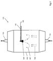
- FIG. 1 The apparatus shown is used to produce a SiO 2 soot body 200.
- a support tube 160 made of aluminum oxide a plurality of arranged in a row Flammhydrolysebrenner 140 is arranged.
- a multiplicity of deposition burners are used, which are reversibly reciprocated for soot deposition in a common burner row along the rotating support, wherein each of the burner flames covers only a partial length of the support tube 160 ,
- the SiO 2 feedstock 105 preferably has more than 95 wt .-%, preferably more than 98 wt .-%, in particular more than 99.5 wt .-% of the polyalkylsiloxane D4 and is supplied to the reaction zone in gaseous form and thereby Oxidation and / or hydrolysis and / or pyrolysis to SiO 2 decomposes.
- the reaction zone is, for example, a burner flame or a plasma.
- SiO 2 particles 148 are formed, which are deposited layer by layer on the deposition surface 160 to form the SiO 2 soot body.
- the SiO 2 particles 148 themselves are in the form of agglomerates or aggregates of SiO 2 primary particles with particle sizes in the nanometer range.
- the flame hydrolysis burners 140 are mounted on a common burner block 141 which is reciprocated parallel to the longitudinal axis 161 of the support tube 160 between two inflection points fixed relative to the longitudinal axis 161 and which is displaceable perpendicular thereto as indicated by the directional arrows 142.
- the burners 140 are made of quartz glass; their center distance from each other is 15 cm.
- the flame hydrolysis burners 140 are each assigned a burner flame 143 which represents a reaction zone in the sense of the invention.
- SiO 2 particles are formed and deposited on the cylinder jacket surface of the carrier tube 160 rotating about its longitudinal axis 161, so that a soot body 200 having an outer diameter of 350 mm is built up in layers.
- a temperature of about 1200 ° C. is established.
- the flame hydrolysis burners 140 are each supplied with oxygen and hydrogen as burner gases and as feed for the formation of the SiO 2 particles the SiO 2 feedstock vapor 107.
- polyalkylsiloxanes encompasses both polyalkylcyclosiloxanes and their linear homologs.
- the production of the SiO 2 feedstock vapor 107 from more than 95% by weight, preferably more than 98% by weight, in particular more than 99.5% by weight, of the polyalkylsiloxane D4 takes place by means of an evaporator system 120, which forms a reservoir 110 for 124, the liquid mixture, a liquid pump 122, a flow meter 123 for liquid, an MFC (m ass f low c ontroller) for the controlled supply of a nitrogen carrier gas stream 152 and a heatable evaporation chamber 125 - includes a spray nozzle 128 - even expansion chamber.
- the reservoir 110, a pump 122 and a spray nozzle 128 are connected to each other by means of flexible metallic lines.
- the reservoir 110 is heated to a temperature of 130-170 ° C, and the heated liquid supplied by the pump 122 via the flow meter 123 in exact dosage of the spray nozzle 128.
- the SiO 2 feedstock 105 is atomized into fine droplets - also referred to as SiO 2 droplets, the SiO 2 droplets having an average diameter of less than 5 ⁇ m, preferably less than 2 ⁇ m.
- a concentration detector for monitoring the composition of the SiO 2 -Einsatzmaterials 105 and / or the SiO 2 -Einsatzdampfes 107 and / or the SiO 2 droplets be provided in the connecting line between the flow meter 123 and atomizer 128th
- the nebulizer 128 - also referred to as nebulizer nozzle - may be an ultrasonic nebulizer.
- This atomizing nozzle 128 ensures that the liquid SiO 2 feedstock is atomized into fine droplets, the droplets having an average diameter of less than 5 ⁇ m, preferably less than 2 ⁇ m.
- the SiO 2 feedstock 105 and / or the droplets can be fed with a nitrogen carrier gas stream via the MFC 123 at a pressure of 1.5 bar to 5 bar.
- the spray nozzle 128 atomizes the SiO 2 feedstock 105 into fine droplets having a maximum diameter of 1 ⁇ m and a narrow droplet size distribution with an average diameter (d 50 value) of 0.7 ⁇ m, and immediately sprays these droplets in an injection phase into the expansion chamber 125 of the evaporator 120 a.
- the evaporator 120 has an internal temperature of 195 ° C, so that the fine liquid droplets evaporate immediately and the vapor stream is fed to a fixed flux divider and is divided by this heat-insulated flexible media supply lines to the individual Abscheidebrenner 140.
- the flow divider also open a supply line for the fuel gases oxygen and hydrogen and an auxiliary gas (oxygen), which is used in the burner flame 143 between the flow of the feedstock and the flow of fuel gas, and counteracts an early mixing.
- oxygen oxygen
- the mixture of fuel gases and the SiO 2 feed steam 107 thus takes place only in the hot zone of the burner flame 143.
- a tube of porous SiO 2 soot Sootrohr
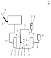
- FIG. 2 and FIG. 3 show the system 100 for producing quartz glass, which uses the inventive method.
- the SiO 2 feedstock material 105 is heated and the atomization takes place by means of a spray nozzle 128, which has an ultrasound system.
- the system 100 has a storage tank 110, from which the liquid SiO 2 feedstock 105 is pumped into a preheating device 115 by means of a pump, not shown.
- the liquid SiO 2 feedstock 105 in the preheater 115 is heated to an elevated temperature.
- the liquid SiO 2 feedstock 105 is pumped into the atomizer nozzle. There is then the atomization of the liquid and the injection of the droplets into the expansion chamber instead.
- the transition of the liquid SiO 2 droplets into the gaseous SiO 2 feedstock steam 107 takes place.
- the SiO 2 feedstock vapor 107 flows to the burner 140, where a pyrolytic or hydrolytic conversion of the SiO 2 feedstock vapor into SiO 2 particles takes place.
- the preheater 115 has an inlet 116 and a drain 117. Through the inlet 116, the SiO 2 feedstock 105 is supplied in the preheater 115. Within the preheater 115 there is a heating of the SiO 2 feedstock 105. This can be done by using a hot oil system or an electric heating element in the walls of the preheater. In order to achieve a uniform heating of the liquid SiO 2 feedstock 105 while avoiding hot areas, it has proved to be advantageous if the preheater 115 has a flow channel which is surrounded by hot oil passages. The thus achievable liquid-to-liquid heat transfer achieves a uniform heating of the liquid SiO 2 feedstock 105. This type of uniform heating ensures that there is no temperature-induced chemical reaction of the polyalkylsiloxanes.
- the heated liquid SiO 2 feedstock 105 is discharged from the preheater 115 into the expansion chamber 125 through a feed line 145.
- the expansion chamber 125 defines an internal volume for the free expansion of the SiO 2 feedstock vapor.
- the temperature of the liquid SiO 2 feedstock is increased above the boiling point of the SiO 2 feedstock at the operating pressure of the expansion chamber .
- a preferred operating temperature for the preheater 115 is about 180 ° C.
- the boiling point of D4 at atmospheric pressure is about 175 ° C.
- backpressure in the preheater is required. In this way, the liquid reactant is maintained as a supercooled (compressed) liquid in the preheater 115.
- the liquid SiO 2 feedstock from the preheater 115 flows through the supply conduit 145 into the interior of the expansion chamber 125.
- the preheater 115 sufficiently heats up the liquid SiO 2 feedstock 105 so that it almost completely vaporizes while it is being pressurized falls into the inner volume of the expansion chamber 125.
- Such an immediate evaporation takes place only if the Preheater 115 has increased the temperature of the liquid SiO 2 feedstock above the boiling point of the SiO 2 feedstock at the operating pressure of the expansion chamber 125.
- the amount of droplets of the SiO 2 feedstock that immediately evaporate thus depends on the amount of heat that is supplied to the liquid SiO 2 feedstock in the preheater 115.
- the system 100 without heating the SiO 2 feedstock 105.
- an atomization of the SiO 2 feedstock takes place only by means of the atomizer nozzle 128, without the SiO 2 feedstock material being heated to an elevated temperature.
- An additional heat input can be effected by a carrier gas, which is also performed, for example, through the atomizer nozzle 128.
- such a variant differs from that in FIG. 3 shown only in that no preheating 115 is needed.
- diluent 152 in particular nitrogen has proved to be advantageous.
- Other diluents such as argon or helium, may also be used if desired. These are gases which are inert with respect to polyalkylsiloxanes, so that oxidation, polymerization or decomposition reactions between the liquid and the carrier gas, in particular under pressure and higher temperature, and thus an irreproducible change in the composition of the feed avoided become.
- the partial pressure of the liquid SiO 2 feedstock - in this case the droplets of the SiO 2 feedstock - in the expansion chamber 125 is reduced and thus its dew point is lowered. This does not require high heating of the SiO 2 feedstock in the preheater 115.
- the evaporation of the SiO 2 feedstock material comprises an injection phase in which the feedstock is atomized into fine droplets in liquid form and an evaporation phase in which the fine droplets are contacted by a hot carrier gas but without contact with Walls of the expansion chamber 125 is completely evaporated quickly and efficiently.
- the FIG. 3 illustrates the evaporation of the invention.
- the heated SiO 2 feedstock 105 is supplied through the supply line 145 to the expansion chamber 125.
- the supply line 145 has a nozzle-like spray nozzle 128.
- the atomizer nozzle 128 - which is preferably an ultrasonic atomizer - the liquid SiO 2 feedstock 105 is atomized into fine droplets, which have a mean diameter of less than 5 .mu.m, preferably less than 2 .mu.m, in particular less than one micron.
- Particularly preferred measurement series were between 0.5 ⁇ m and 20 nm (d 50 value).
- the median value or d 50 value is the most important parameter as a measure of the average particle size.
- the d 50 value describes the value at which 50 percent of the droplets are finer and the others 50 percent coarser than d 50 .
- the nitrogen stream has a temperature which corresponds essentially - ie to +/- 10 ° C - the temperature of the liquid SiO 2 feedstock 105.
- the nitrogen stream may flow counter to the spray direction of the liquid SiO 2 feedstock 105 so as to ensure high mixing and heat transfer.
Landscapes
- Chemical & Material Sciences (AREA)
- Engineering & Computer Science (AREA)
- Materials Engineering (AREA)
- Organic Chemistry (AREA)
- Chemical Kinetics & Catalysis (AREA)
- Manufacturing & Machinery (AREA)
- Geochemistry & Mineralogy (AREA)
- Life Sciences & Earth Sciences (AREA)
- General Life Sciences & Earth Sciences (AREA)
- General Chemical & Material Sciences (AREA)
- Dispersion Chemistry (AREA)
- Glass Melting And Manufacturing (AREA)
- Silicon Compounds (AREA)
Applications Claiming Priority (3)
| Application Number | Priority Date | Filing Date | Title |
|---|---|---|---|
| DE102011119339A DE102011119339A1 (de) | 2011-11-25 | 2011-11-25 | Zerstäubungsverfahren zur Herstellung von synthetischem Quarzglas |
| US201161569163P | 2011-12-09 | 2011-12-09 | |
| PCT/EP2012/073345 WO2013076195A1 (de) | 2011-11-25 | 2012-11-22 | Verfahren zur herstellung von synthetischem quarzglas durch abscheidung aus der dampfphase und mittels zerstäubung des flüssigen siloxaneinsatzmaterials |
Publications (2)
| Publication Number | Publication Date |
|---|---|
| EP2782877A1 EP2782877A1 (de) | 2014-10-01 |
| EP2782877B1 true EP2782877B1 (de) | 2016-05-25 |
Family
ID=48287834
Family Applications (1)
| Application Number | Title | Priority Date | Filing Date |
|---|---|---|---|
| EP12794916.2A Active EP2782877B1 (de) | 2011-11-25 | 2012-11-22 | Verfahren zur herstellung von synthetischem quarzglas durch abscheidung aus der dampfphase und mittels zerstäubung des flüssigen siloxaneinsatzmaterials |
Country Status (7)
| Country | Link |
|---|---|
| US (1) | US8984911B2 (enExample) |
| EP (1) | EP2782877B1 (enExample) |
| JP (1) | JP6133319B2 (enExample) |
| KR (1) | KR101625843B1 (enExample) |
| CN (1) | CN103946168B (enExample) |
| DE (1) | DE102011119339A1 (enExample) |
| WO (1) | WO2013076195A1 (enExample) |
Families Citing this family (12)
| Publication number | Priority date | Publication date | Assignee | Title |
|---|---|---|---|---|
| DE102011121190A1 (de) * | 2011-12-16 | 2013-06-20 | Heraeus Quarzglas Gmbh & Co. Kg | OMCTS-Verdampfungsverfahren |
| WO2014047724A1 (en) | 2012-09-26 | 2014-04-03 | Ledtech International Inc. | Multilayer optical interference filter |
| DE102013202256B3 (de) * | 2013-02-12 | 2014-07-17 | Heraeus Quarzglas Gmbh & Co. Kg | Verfahren zur Herstellung von Titan-dotiertem synthetischen Quarzglas und dessen Verwendung |
| US10464838B2 (en) * | 2015-01-13 | 2019-11-05 | Asi/Silica Machinery, Llc | Enhanced particle deposition system and method |
| EP3424883A1 (de) * | 2017-07-05 | 2019-01-09 | Evonik Degussa GmbH | Sprühverdampfung eines flüssigen rohstoffes zur herstellung von siliciumdioxid und metalloxiden |
| JP6793676B2 (ja) * | 2018-04-02 | 2020-12-02 | 信越化学工業株式会社 | 光ファイバ用多孔質ガラス母材の製造装置および製造方法 |
| CN109373196A (zh) * | 2018-12-05 | 2019-02-22 | 上海正帆科技股份有限公司 | 一种八甲基环四硅氧烷的输送及汽化系统和方法 |
| JP7058627B2 (ja) | 2019-06-11 | 2022-04-22 | 信越化学工業株式会社 | 光ファイバ用多孔質ガラス母材の製造装置および製造方法 |
| CN112028466B (zh) * | 2020-09-01 | 2021-08-31 | 长飞光纤光缆股份有限公司 | 一种用于制备光纤预制棒的有机硅原料蒸发装置 |
| JP7428632B2 (ja) | 2020-12-14 | 2024-02-06 | 信越化学工業株式会社 | 多孔質ガラス母材の製造方法及び製造装置 |
| CN115583791B (zh) * | 2022-10-18 | 2023-12-01 | 长飞光纤光缆股份有限公司 | 一种适用于ovd工艺的d4快速气化装置 |
| CN117645406B (zh) * | 2023-12-22 | 2025-08-01 | 湖北菲利华石英玻璃股份有限公司 | 一种低膨胀系数石英玻璃锭的生产方法及生产装置 |
Family Cites Families (93)
| Publication number | Priority date | Publication date | Assignee | Title |
|---|---|---|---|---|
| US2552247A (en) | 1949-04-08 | 1951-05-08 | Gen Electric | Preparation of organopolysiloxanes |
| US3493533A (en) | 1956-10-12 | 1970-02-03 | Union Carbide Corp | Organosilicon compounds and processes for producing the same |
| US3629309A (en) | 1956-10-12 | 1971-12-21 | Union Carbide Corp | Organosilicon compounds and processes for producing the same |
| US3274154A (en) | 1962-08-02 | 1966-09-20 | Midland Silicones Ltd | Polymerization of cyclic siloxanes |
| US3332974A (en) | 1964-01-23 | 1967-07-25 | Gen Electric | Purification of cyclic organopolysiloxanes with heat-activated metal hydrides |
| US4022152A (en) | 1969-03-29 | 1977-05-10 | Deutsche Gold- Und Silber-Scheideanstalt Vormals Roessler | Apparatus for making particulate materials, particularly oxides, hydrophobic |
| US3903047A (en) | 1973-10-23 | 1975-09-02 | Gen Electric | Process for the production of silanol-stopped diorgano-polysiloxanes |
| US3978104A (en) | 1974-04-24 | 1976-08-31 | General Electric Company | Process for producing diorganopolysiloxane oils |
| DE2435704C3 (de) | 1974-07-25 | 1987-06-19 | Hoechst Ag, 6230 Frankfurt | Verfahren und Vorrichtung zur kontinuierlichen Entfernung von Restgehalten an Monomeren aus wäßrigen Dispersionen von Polymerisaten des Vinylchlorids |
| US4158092A (en) | 1974-07-25 | 1979-06-12 | Hoechst Aktiengesellschaft | Process for the manufacture of vinyl chloride polymer dispersions with a low monomer content |
| US3998865A (en) | 1975-03-12 | 1976-12-21 | General Electric Company | Process for the stabilization of hexamethyl-cyclotrisiloxane and the stabilized compositions resulting therefrom |
| US4096160A (en) | 1976-04-21 | 1978-06-20 | General Electric Company | Continuous devolatilization of silanol-terminated silicone polymer |
| US4220460A (en) | 1979-02-05 | 1980-09-02 | Western Electric Company, Inc. | Vapor delivery system and method |
| US5021221A (en) | 1980-10-20 | 1991-06-04 | Aero Chem Research Lab., Inc. | Apparatus for producing high purity silicon from flames of sodium and silicon tetrachloride |
| USRE32107E (en) | 1982-12-23 | 1986-04-08 | Dow Corning Corporation | Carbon-containing monolithic glasses and ceramics prepared by a sol-gel process |
| JPS6049033A (ja) | 1983-08-29 | 1985-03-18 | Shin Etsu Chem Co Ltd | オルガノポリシロキサンの製造方法 |
| US4704271A (en) | 1984-04-03 | 1987-11-03 | American Cyanamid Company | Water-in-oil emulsion antiperspirant stick |
| US4892890A (en) | 1984-11-01 | 1990-01-09 | G. D. Searle And Company | External analgesic compositions |
| CH665202A5 (de) | 1985-01-03 | 1988-04-29 | Troitsky Vladimir N | Verfahren zur herstellung von feindispersem siliziumdioxid. |
| US4556726A (en) * | 1985-01-09 | 1985-12-03 | Union Carbide Corporation | Process for converting octamethylcyclotetrasiloxane to decamethylcyclopentasiloxane |
| US4613380A (en) | 1985-04-01 | 1986-09-23 | Dow Corning Corporation | Method for removing lipid deposits from contact lenses |
| US4889845A (en) | 1986-06-09 | 1989-12-26 | American Cyanamid Company | Vehicle for topical application of pharmaceuticals |
| US4720353A (en) | 1987-04-14 | 1988-01-19 | Richardson-Vicks Inc. | Stable pharmaceutical w/o emulsion composition |
| US4948578A (en) | 1987-05-15 | 1990-08-14 | Lever Brothers Company | Transparent antiperspirant stick compositions |
| US5143661A (en) | 1987-05-26 | 1992-09-01 | American Cyanamid Company | Silicone-hardened pharmaceutical microcapsules |
| US4824985A (en) | 1987-06-11 | 1989-04-25 | Dow Corning Corporation | Novel route to Ca8 Si4 O12 Cl8, alkoxycyclotetrasiloxanes, aryloxycyclotetrasiloxanes, alkylcyclotetrasiloxanes and arylcyclotetrasiloxanes from wollastonite (Ca SiO3) |
| US4847069A (en) | 1987-10-22 | 1989-07-11 | The Procter & Gamble Company | Photoprotection compositions comprising sorbohydroxamic acid and an anti-inflammatory agent |
| US4847072A (en) | 1987-10-22 | 1989-07-11 | The Procter & Gamble Company | Photoprotection compositions comprising tocopherol sorbate |
| US4954332A (en) | 1987-10-22 | 1990-09-04 | The Procter & Gamble Company | Photoprotection compositions comprising tocopherol sorbate and an anti-inflammatory agent |
| US4847071A (en) | 1987-10-22 | 1989-07-11 | The Procter & Gamble Company | Photoprotection compositions comprising tocopherol sorbate and an anti-inflammatory agent |
| US5039513A (en) | 1987-10-22 | 1991-08-13 | The Procter & Gamble Company | Photoprotection compositions and methods comprising sorbohydroxamic acid |
| US4946671A (en) | 1987-10-22 | 1990-08-07 | The Procter & Gamble Company | Photoprotection compositions comprising sorbohydroxamic acid and an anti-inflammatory agent |
| US4869897A (en) | 1987-10-22 | 1989-09-26 | The Procter & Gamble Company | Photoprotection compositions comprising sorbohydroxamic acid |
| GB8817961D0 (en) | 1988-07-28 | 1988-09-01 | Dow Corning Ltd | Compositions & process for treatment of textiles |
| JPH0288639A (ja) | 1988-09-27 | 1990-03-28 | Shin Etsu Chem Co Ltd | オルガノポリシロキサン化合物 |
| GB8905966D0 (en) | 1989-03-15 | 1989-04-26 | Tsl Group Plc | Improved vitreous silica products |
| US4954335A (en) | 1989-05-31 | 1990-09-04 | Helene Curtis, Inc. | Clear conditioning composition and method to impart improved properties to the hair |
| US5292530A (en) | 1991-06-02 | 1994-03-08 | Helene Curtis, Inc. | Stable anhydrous topically-active composition and suspending agent therefor |
| US5110335A (en) * | 1990-06-25 | 1992-05-05 | At&T Bell Laboratories | Method of glass soot deposition using ultrasonic nozzle |
| US5043002A (en) * | 1990-08-16 | 1991-08-27 | Corning Incorporated | Method of making fused silica by decomposing siloxanes |
| US5152819A (en) * | 1990-08-16 | 1992-10-06 | Corning Incorporated | Method of making fused silica |
| FR2666347B1 (fr) | 1990-08-31 | 1992-12-11 | Oreal | Compositions de lavage a base de silicones et procede de mise en óoeuvre. |
| DE4029071C2 (de) | 1990-09-13 | 1994-03-31 | Massah Sobhy Ahmed Dipl Ing El | Vorrichtung zum Verdampfen von flüssigen Produkten, Verfahren zum Betreiben der Vorrichtung sowie Verwendung der Vorrichtung als Dampferzeuger oder Kondensator |
| US5211732A (en) | 1990-09-20 | 1993-05-18 | Corning Incorporated | Method for forming a porous glass preform |
| US5232689A (en) | 1990-12-21 | 1993-08-03 | Dow Corning Corporation | Translucent antiperspirant compositions |
| GB9105372D0 (en) | 1991-03-14 | 1991-05-01 | Dow Corning Sa | Method of making siloxane compositions |
| US5250278A (en) | 1991-06-19 | 1993-10-05 | Phillips Petroleum Company | Method for producing a ceramic product |
| US5154744A (en) | 1991-08-26 | 1992-10-13 | Corning Incorporated | Method of making titania-doped fused silica |
| US5338535A (en) | 1991-10-04 | 1994-08-16 | The Safe & Dry Company, Inc. | Non-aqueous liquid powder |
| DE4204406C2 (de) | 1992-02-14 | 1995-04-06 | Heraeus Quarzglas | Verfahren zur Herstellung eines homogenen, schlierenfreien Körpers aus Quarzglas oder aus einem hochkieselsäurehaltigen Glas durch Umformen eines stabförmigen Ausgangskörpers |
| US5275761A (en) | 1992-04-15 | 1994-01-04 | Helene Curtis, Inc. | Conditioning shampoo composition and method of preparing and using the same |
| ZA931613B (en) | 1992-04-15 | 1993-11-15 | Curtis Helene Ind Inc | Conditioning shampoo composition and method of preparing and using the same |
| US5270036A (en) | 1992-10-13 | 1993-12-14 | Dow Corning Corporation | Permanent waving with silicones |
| US5300285A (en) | 1992-10-13 | 1994-04-05 | Dow Corning Corporation | Permanent waving with silicones |
| US5279818A (en) | 1992-10-13 | 1994-01-18 | Dow Corning Corporation | Permanent waving with silicones |
| US5330747A (en) | 1993-02-03 | 1994-07-19 | Dow Corning Corporation | Cosmetics with enhanced durability |
| JPH06240000A (ja) | 1993-02-17 | 1994-08-30 | Shin Etsu Chem Co Ltd | 分岐状オルガノポリシロキサンの製造方法 |
| US5326557A (en) | 1993-04-06 | 1994-07-05 | Dow Corning Corporation | Moisturizing compositions containing organosilicon compounds |
| JP3274737B2 (ja) | 1993-04-09 | 2002-04-15 | オリンパス光学工業株式会社 | 洗浄方法および洗浄スプレー装置 |
| EP0622452B1 (en) | 1993-04-29 | 1999-05-26 | Olympus Optical Co., Ltd. | Cleaning process |
| JP2826939B2 (ja) | 1993-05-28 | 1998-11-18 | 東レ・ダウコーニング・シリコーン株式会社 | ジオルガノポリシロキサンの製造方法 |
| US5302382A (en) | 1993-06-03 | 1994-04-12 | Dow Corning Corporation | Silicone containing personal care products |
| GB9312634D0 (en) | 1993-06-18 | 1993-08-04 | Tsl Group Plc | Improvements in vitreous silica manufacture |
| JP2869304B2 (ja) | 1993-08-18 | 1999-03-10 | 信越化学工業株式会社 | シラノール基含有オルガノポリシロキサンの製造方法 |
| DE69408919T2 (de) | 1993-08-18 | 1998-10-01 | Shinetsu Chemical Co | Verfahren zur Herstellung von Polydimethylsiloxanen |
| US5356451A (en) | 1993-12-20 | 1994-10-18 | Corning Incorporated | Method and apparatus for vaporization of liquid reactants |
| US5403402A (en) | 1994-01-07 | 1995-04-04 | Dow Corning Corporation | Method of removing coating from surfaces |
| JP3194667B2 (ja) | 1994-03-26 | 2001-07-30 | 信越石英株式会社 | 光学用合成石英ガラス成形体及びその製造方法 |
| US5426168A (en) | 1994-04-29 | 1995-06-20 | Dow Corning Corporation | Method of preparing an organically-modified, heat-curable silicone resin and the resin produced thereby |
| US5632797A (en) | 1994-12-30 | 1997-05-27 | Corning Incorporated | Method of providing vaporized halide-free, silicon-containing compounds |
| DE19501733C1 (de) | 1995-01-20 | 1996-05-15 | Heraeus Quarzglas | Vorrichtung zur Aufteilung eines Gasstromes in mehrere Teilgasströme |
| EP0747327B2 (en) | 1995-06-07 | 2003-08-27 | Corning Incorporated | Method of thermally treating and consolidating silica preforms for reducing laser-induced optical damage in silica |
| US5703191A (en) * | 1995-09-01 | 1997-12-30 | Corning Incorporated | Method for purifying polyalkylsiloxanes and the resulting products |
| US6312656B1 (en) * | 1995-12-19 | 2001-11-06 | Corning Incorporated | Method for forming silica by combustion of liquid reactants using oxygen |
| US5879649A (en) * | 1995-12-19 | 1999-03-09 | Corning Incorporated | Method for purifying polyalkylsiloxanes and the resulting products |
| US6244575B1 (en) * | 1996-10-02 | 2001-06-12 | Micron Technology, Inc. | Method and apparatus for vaporizing liquid precursors and system for using same |
| US5979185A (en) * | 1997-07-16 | 1999-11-09 | Corning Incorporated | Method and apparatus for forming silica by combustion of liquid reactants using a heater |
| JPH11116247A (ja) * | 1997-10-09 | 1999-04-27 | Nikon Corp | 合成石英ガラス製造方法 |
| US6546757B1 (en) * | 1998-07-28 | 2003-04-15 | Brown University Research Foundation | Liquid spray pyrolysis method for the fabrication of optical fiber preforms, with reactant mixing |
| US6705127B1 (en) * | 1998-10-30 | 2004-03-16 | Corning Incorporated | Methods of manufacturing soot for optical fiber preforms and preforms made by the methods |
| US6598425B1 (en) * | 2000-03-08 | 2003-07-29 | Corning Incorporated | Method for collecting soot |
| JP2004511092A (ja) | 2000-10-03 | 2004-04-08 | コーニング インコーポレイテッド | フォトリソグラフィの方法およびフォトリソグラフィ装置 |
| KR20040078643A (ko) * | 2001-12-04 | 2004-09-10 | 프라이맥스 인코포레이티드 | 증기를 증착실에 공급하는 방법 및 화학 증착 기화기 |
| JP4158009B2 (ja) | 2001-12-11 | 2008-10-01 | 信越化学工業株式会社 | 合成石英ガラスインゴット及び合成石英ガラスの製造方法 |
| DE10302914B4 (de) | 2003-01-24 | 2005-12-29 | Heraeus Quarzglas Gmbh & Co. Kg | Verfahren zur Herstellung von synthetischem Quarzglas |
| US7534733B2 (en) | 2004-02-23 | 2009-05-19 | Corning Incorporated | Synthetic silica glass optical material having high resistance to laser induced damage |
| US7589039B2 (en) | 2004-12-29 | 2009-09-15 | Corning Incorporated | Synthetic silica having low polarization-induced birefringence, method of making same and lithographic device comprising same |
| US7506521B2 (en) | 2004-12-29 | 2009-03-24 | Corning Incorporated | High transmission synthetic silica glass and method of making same |
| US7506522B2 (en) | 2004-12-29 | 2009-03-24 | Corning Incorporated | High refractive index homogeneity fused silica glass and method of making same |
| JP2006299335A (ja) * | 2005-04-19 | 2006-11-02 | Fujimori Gijutsu Kenkyusho:Kk | 成膜方法及びその方法に使用する成膜装置並びに気化装置 |
| DE102007024725B4 (de) | 2007-05-25 | 2011-09-29 | Heraeus Quarzglas Gmbh & Co. Kg | Abscheidebrenner und Verfahren für dessen Herstellung, dessen Verwendung in einer Brenneranordnung sowie Verfahren zur Herstellung eines Rohlings aus synthetischem Quarzglas unter Einsatz der Brenneranordnung |
| EP2072644A1 (en) | 2007-12-21 | 2009-06-24 | ETH Zürich, ETH Transfer | Device and method for the electrochemical deposition of chemical compounds and alloys with controlled composition and or stoichiometry |
| US20120276291A1 (en) | 2011-04-28 | 2012-11-01 | Bird Chester D | Methods and Apparatuses for Reducing Gelation of Glass Precursor Materials During Vaporization |
-
2011
- 2011-11-25 DE DE102011119339A patent/DE102011119339A1/de not_active Withdrawn
-
2012
- 2012-11-22 WO PCT/EP2012/073345 patent/WO2013076195A1/de not_active Ceased
- 2012-11-22 JP JP2014542831A patent/JP6133319B2/ja active Active
- 2012-11-22 KR KR1020147017200A patent/KR101625843B1/ko active Active
- 2012-11-22 EP EP12794916.2A patent/EP2782877B1/de active Active
- 2012-11-22 CN CN201280057983.1A patent/CN103946168B/zh active Active
- 2012-11-23 US US13/684,394 patent/US8984911B2/en active Active
Also Published As
| Publication number | Publication date |
|---|---|
| WO2013076195A1 (de) | 2013-05-30 |
| CN103946168B (zh) | 2017-02-22 |
| JP6133319B2 (ja) | 2017-05-24 |
| DE102011119339A1 (de) | 2013-05-29 |
| JP2015500785A (ja) | 2015-01-08 |
| KR101625843B1 (ko) | 2016-06-01 |
| CN103946168A (zh) | 2014-07-23 |
| EP2782877A1 (de) | 2014-10-01 |
| US20130133376A1 (en) | 2013-05-30 |
| US8984911B2 (en) | 2015-03-24 |
| KR20140098814A (ko) | 2014-08-08 |
Similar Documents
| Publication | Publication Date | Title |
|---|---|---|
| EP2782877B1 (de) | Verfahren zur herstellung von synthetischem quarzglas durch abscheidung aus der dampfphase und mittels zerstäubung des flüssigen siloxaneinsatzmaterials | |
| EP2791069B1 (de) | Verfahren zur herstellung von synthetischem quarzglas | |
| EP2782880B1 (de) | Verfahren zur herstellung von synthetischem quarzglas nach der sootmethode | |
| EP2782875B1 (de) | Verfahren zur herstellung von synthetischem quarzglas durch abscheidung von silicassoot aus der dampfphase auf einer unterlage | |
| DE69029793T2 (de) | Verfahren zum Zuführen eines Reaktionspartners zu einer Abscheidungsvorrichtung für Glasruss. | |
| EP3004001B1 (de) | Verfahren zur herstellung von synthetischem quarzglas | |
| DE102011119373A1 (de) | Verfahren zur Herstellung von synthetischem Quarzglas | |
| DE69511288T2 (de) | Vertikal angeordneter schüttschicht-filmverdampfer für halogenidfreie silizium enthaltende verbindungen | |
| DE69922452T2 (de) | Verfahren und Brenner zum Bilden von Siliciumdioxid enthaltenden Russ | |
| DE102013202256B3 (de) | Verfahren zur Herstellung von Titan-dotiertem synthetischen Quarzglas und dessen Verwendung | |
| WO2013092553A1 (de) | Verfahren zur herstellung von synthetischem quarzglas | |
| WO2020025561A1 (de) | Verfahren und vorrichtung zum reproduzierbaren erzeugen einer preform für die glasfaserherstellung |
Legal Events
| Date | Code | Title | Description |
|---|---|---|---|
| PUAI | Public reference made under article 153(3) epc to a published international application that has entered the european phase |
Free format text: ORIGINAL CODE: 0009012 |
|
| 17P | Request for examination filed |
Effective date: 20140530 |
|
| AK | Designated contracting states |
Kind code of ref document: A1 Designated state(s): AL AT BE BG CH CY CZ DE DK EE ES FI FR GB GR HR HU IE IS IT LI LT LU LV MC MK MT NL NO PL PT RO RS SE SI SK SM TR |
|
| DAX | Request for extension of the european patent (deleted) | ||
| GRAP | Despatch of communication of intention to grant a patent |
Free format text: ORIGINAL CODE: EPIDOSNIGR1 |
|
| INTG | Intention to grant announced |
Effective date: 20151215 |
|
| GRAS | Grant fee paid |
Free format text: ORIGINAL CODE: EPIDOSNIGR3 |
|
| GRAA | (expected) grant |
Free format text: ORIGINAL CODE: 0009210 |
|
| AK | Designated contracting states |
Kind code of ref document: B1 Designated state(s): AL AT BE BG CH CY CZ DE DK EE ES FI FR GB GR HR HU IE IS IT LI LT LU LV MC MK MT NL NO PL PT RO RS SE SI SK SM TR |
|
| REG | Reference to a national code |
Ref country code: GB Ref legal event code: FG4D Free format text: NOT ENGLISH |
|
| REG | Reference to a national code |
Ref country code: CH Ref legal event code: EP |
|
| REG | Reference to a national code |
Ref country code: IE Ref legal event code: FG4D Free format text: LANGUAGE OF EP DOCUMENT: GERMAN Ref country code: AT Ref legal event code: REF Ref document number: 802164 Country of ref document: AT Kind code of ref document: T Effective date: 20160615 |
|
| REG | Reference to a national code |
Ref country code: DE Ref legal event code: R096 Ref document number: 502012007269 Country of ref document: DE |
|
| REG | Reference to a national code |
Ref country code: LT Ref legal event code: MG4D |
|
| REG | Reference to a national code |
Ref country code: NL Ref legal event code: MP Effective date: 20160525 |
|
| PG25 | Lapsed in a contracting state [announced via postgrant information from national office to epo] |
Ref country code: LT Free format text: LAPSE BECAUSE OF FAILURE TO SUBMIT A TRANSLATION OF THE DESCRIPTION OR TO PAY THE FEE WITHIN THE PRESCRIBED TIME-LIMIT Effective date: 20160525 Ref country code: FI Free format text: LAPSE BECAUSE OF FAILURE TO SUBMIT A TRANSLATION OF THE DESCRIPTION OR TO PAY THE FEE WITHIN THE PRESCRIBED TIME-LIMIT Effective date: 20160525 Ref country code: NO Free format text: LAPSE BECAUSE OF FAILURE TO SUBMIT A TRANSLATION OF THE DESCRIPTION OR TO PAY THE FEE WITHIN THE PRESCRIBED TIME-LIMIT Effective date: 20160825 Ref country code: NL Free format text: LAPSE BECAUSE OF FAILURE TO SUBMIT A TRANSLATION OF THE DESCRIPTION OR TO PAY THE FEE WITHIN THE PRESCRIBED TIME-LIMIT Effective date: 20160525 |
|
| REG | Reference to a national code |
Ref country code: FR Ref legal event code: PLFP Year of fee payment: 5 |
|
| PG25 | Lapsed in a contracting state [announced via postgrant information from national office to epo] |
Ref country code: RS Free format text: LAPSE BECAUSE OF FAILURE TO SUBMIT A TRANSLATION OF THE DESCRIPTION OR TO PAY THE FEE WITHIN THE PRESCRIBED TIME-LIMIT Effective date: 20160525 Ref country code: GR Free format text: LAPSE BECAUSE OF FAILURE TO SUBMIT A TRANSLATION OF THE DESCRIPTION OR TO PAY THE FEE WITHIN THE PRESCRIBED TIME-LIMIT Effective date: 20160826 Ref country code: ES Free format text: LAPSE BECAUSE OF FAILURE TO SUBMIT A TRANSLATION OF THE DESCRIPTION OR TO PAY THE FEE WITHIN THE PRESCRIBED TIME-LIMIT Effective date: 20160525 Ref country code: SE Free format text: LAPSE BECAUSE OF FAILURE TO SUBMIT A TRANSLATION OF THE DESCRIPTION OR TO PAY THE FEE WITHIN THE PRESCRIBED TIME-LIMIT Effective date: 20160525 Ref country code: PT Free format text: LAPSE BECAUSE OF FAILURE TO SUBMIT A TRANSLATION OF THE DESCRIPTION OR TO PAY THE FEE WITHIN THE PRESCRIBED TIME-LIMIT Effective date: 20160926 Ref country code: LV Free format text: LAPSE BECAUSE OF FAILURE TO SUBMIT A TRANSLATION OF THE DESCRIPTION OR TO PAY THE FEE WITHIN THE PRESCRIBED TIME-LIMIT Effective date: 20160525 |
|
| PG25 | Lapsed in a contracting state [announced via postgrant information from national office to epo] |
Ref country code: RO Free format text: LAPSE BECAUSE OF FAILURE TO SUBMIT A TRANSLATION OF THE DESCRIPTION OR TO PAY THE FEE WITHIN THE PRESCRIBED TIME-LIMIT Effective date: 20160525 Ref country code: DK Free format text: LAPSE BECAUSE OF FAILURE TO SUBMIT A TRANSLATION OF THE DESCRIPTION OR TO PAY THE FEE WITHIN THE PRESCRIBED TIME-LIMIT Effective date: 20160525 Ref country code: SK Free format text: LAPSE BECAUSE OF FAILURE TO SUBMIT A TRANSLATION OF THE DESCRIPTION OR TO PAY THE FEE WITHIN THE PRESCRIBED TIME-LIMIT Effective date: 20160525 Ref country code: EE Free format text: LAPSE BECAUSE OF FAILURE TO SUBMIT A TRANSLATION OF THE DESCRIPTION OR TO PAY THE FEE WITHIN THE PRESCRIBED TIME-LIMIT Effective date: 20160525 Ref country code: CZ Free format text: LAPSE BECAUSE OF FAILURE TO SUBMIT A TRANSLATION OF THE DESCRIPTION OR TO PAY THE FEE WITHIN THE PRESCRIBED TIME-LIMIT Effective date: 20160525 |
|
| PG25 | Lapsed in a contracting state [announced via postgrant information from national office to epo] |
Ref country code: BE Free format text: LAPSE BECAUSE OF NON-PAYMENT OF DUE FEES Effective date: 20161130 Ref country code: PL Free format text: LAPSE BECAUSE OF FAILURE TO SUBMIT A TRANSLATION OF THE DESCRIPTION OR TO PAY THE FEE WITHIN THE PRESCRIBED TIME-LIMIT Effective date: 20160525 Ref country code: SM Free format text: LAPSE BECAUSE OF FAILURE TO SUBMIT A TRANSLATION OF THE DESCRIPTION OR TO PAY THE FEE WITHIN THE PRESCRIBED TIME-LIMIT Effective date: 20160525 |
|
| REG | Reference to a national code |
Ref country code: DE Ref legal event code: R097 Ref document number: 502012007269 Country of ref document: DE |
|
| PLBE | No opposition filed within time limit |
Free format text: ORIGINAL CODE: 0009261 |
|
| STAA | Information on the status of an ep patent application or granted ep patent |
Free format text: STATUS: NO OPPOSITION FILED WITHIN TIME LIMIT |
|
| 26N | No opposition filed |
Effective date: 20170228 |
|
| PG25 | Lapsed in a contracting state [announced via postgrant information from national office to epo] |
Ref country code: SI Free format text: LAPSE BECAUSE OF FAILURE TO SUBMIT A TRANSLATION OF THE DESCRIPTION OR TO PAY THE FEE WITHIN THE PRESCRIBED TIME-LIMIT Effective date: 20160525 |
|
| REG | Reference to a national code |
Ref country code: CH Ref legal event code: PL |
|
| PG25 | Lapsed in a contracting state [announced via postgrant information from national office to epo] |
Ref country code: LI Free format text: LAPSE BECAUSE OF NON-PAYMENT OF DUE FEES Effective date: 20161130 Ref country code: CH Free format text: LAPSE BECAUSE OF NON-PAYMENT OF DUE FEES Effective date: 20161130 |
|
| REG | Reference to a national code |
Ref country code: IE Ref legal event code: MM4A |
|
| PG25 | Lapsed in a contracting state [announced via postgrant information from national office to epo] |
Ref country code: LU Free format text: LAPSE BECAUSE OF NON-PAYMENT OF DUE FEES Effective date: 20161130 |
|
| REG | Reference to a national code |
Ref country code: FR Ref legal event code: PLFP Year of fee payment: 6 |
|
| PG25 | Lapsed in a contracting state [announced via postgrant information from national office to epo] |
Ref country code: IE Free format text: LAPSE BECAUSE OF NON-PAYMENT OF DUE FEES Effective date: 20161122 |
|
| REG | Reference to a national code |
Ref country code: BE Ref legal event code: MM Effective date: 20161130 |
|
| PG25 | Lapsed in a contracting state [announced via postgrant information from national office to epo] |
Ref country code: HU Free format text: LAPSE BECAUSE OF FAILURE TO SUBMIT A TRANSLATION OF THE DESCRIPTION OR TO PAY THE FEE WITHIN THE PRESCRIBED TIME-LIMIT; INVALID AB INITIO Effective date: 20121122 |
|
| PG25 | Lapsed in a contracting state [announced via postgrant information from national office to epo] |
Ref country code: MC Free format text: LAPSE BECAUSE OF FAILURE TO SUBMIT A TRANSLATION OF THE DESCRIPTION OR TO PAY THE FEE WITHIN THE PRESCRIBED TIME-LIMIT Effective date: 20160525 Ref country code: HR Free format text: LAPSE BECAUSE OF FAILURE TO SUBMIT A TRANSLATION OF THE DESCRIPTION OR TO PAY THE FEE WITHIN THE PRESCRIBED TIME-LIMIT Effective date: 20160525 Ref country code: IS Free format text: LAPSE BECAUSE OF FAILURE TO SUBMIT A TRANSLATION OF THE DESCRIPTION OR TO PAY THE FEE WITHIN THE PRESCRIBED TIME-LIMIT Effective date: 20160525 Ref country code: CY Free format text: LAPSE BECAUSE OF FAILURE TO SUBMIT A TRANSLATION OF THE DESCRIPTION OR TO PAY THE FEE WITHIN THE PRESCRIBED TIME-LIMIT Effective date: 20160525 Ref country code: MK Free format text: LAPSE BECAUSE OF FAILURE TO SUBMIT A TRANSLATION OF THE DESCRIPTION OR TO PAY THE FEE WITHIN THE PRESCRIBED TIME-LIMIT Effective date: 20160525 |
|
| PG25 | Lapsed in a contracting state [announced via postgrant information from national office to epo] |
Ref country code: BG Free format text: LAPSE BECAUSE OF FAILURE TO SUBMIT A TRANSLATION OF THE DESCRIPTION OR TO PAY THE FEE WITHIN THE PRESCRIBED TIME-LIMIT Effective date: 20160525 |
|
| PG25 | Lapsed in a contracting state [announced via postgrant information from national office to epo] |
Ref country code: MT Free format text: LAPSE BECAUSE OF FAILURE TO SUBMIT A TRANSLATION OF THE DESCRIPTION OR TO PAY THE FEE WITHIN THE PRESCRIBED TIME-LIMIT Effective date: 20160525 |
|
| PG25 | Lapsed in a contracting state [announced via postgrant information from national office to epo] |
Ref country code: TR Free format text: LAPSE BECAUSE OF FAILURE TO SUBMIT A TRANSLATION OF THE DESCRIPTION OR TO PAY THE FEE WITHIN THE PRESCRIBED TIME-LIMIT Effective date: 20160525 Ref country code: AL Free format text: LAPSE BECAUSE OF FAILURE TO SUBMIT A TRANSLATION OF THE DESCRIPTION OR TO PAY THE FEE WITHIN THE PRESCRIBED TIME-LIMIT Effective date: 20160525 |
|
| REG | Reference to a national code |
Ref country code: AT Ref legal event code: MM01 Ref document number: 802164 Country of ref document: AT Kind code of ref document: T Effective date: 20171122 |
|
| PG25 | Lapsed in a contracting state [announced via postgrant information from national office to epo] |
Ref country code: AT Free format text: LAPSE BECAUSE OF NON-PAYMENT OF DUE FEES Effective date: 20171122 |
|
| PGFP | Annual fee paid to national office [announced via postgrant information from national office to epo] |
Ref country code: FR Payment date: 20191120 Year of fee payment: 8 |
|
| PGFP | Annual fee paid to national office [announced via postgrant information from national office to epo] |
Ref country code: GB Payment date: 20191120 Year of fee payment: 8 |
|
| GBPC | Gb: european patent ceased through non-payment of renewal fee |
Effective date: 20201122 |
|
| PG25 | Lapsed in a contracting state [announced via postgrant information from national office to epo] |
Ref country code: FR Free format text: LAPSE BECAUSE OF NON-PAYMENT OF DUE FEES Effective date: 20201130 |
|
| PG25 | Lapsed in a contracting state [announced via postgrant information from national office to epo] |
Ref country code: GB Free format text: LAPSE BECAUSE OF NON-PAYMENT OF DUE FEES Effective date: 20201122 |
|
| P01 | Opt-out of the competence of the unified patent court (upc) registered |
Effective date: 20230530 |
|
| PGFP | Annual fee paid to national office [announced via postgrant information from national office to epo] |
Ref country code: DE Payment date: 20241121 Year of fee payment: 13 |
|
| PGFP | Annual fee paid to national office [announced via postgrant information from national office to epo] |
Ref country code: IT Payment date: 20241126 Year of fee payment: 13 |
|
| REG | Reference to a national code |
Ref country code: DE Ref legal event code: R082 Ref document number: 502012007269 Country of ref document: DE Representative=s name: BRAND, NORMEN, DR. RER. NAT., DE |