EP2791069B1 - Verfahren zur herstellung von synthetischem quarzglas - Google Patents
Verfahren zur herstellung von synthetischem quarzglas Download PDFInfo
- Publication number
- EP2791069B1 EP2791069B1 EP12806426.8A EP12806426A EP2791069B1 EP 2791069 B1 EP2791069 B1 EP 2791069B1 EP 12806426 A EP12806426 A EP 12806426A EP 2791069 B1 EP2791069 B1 EP 2791069B1
- Authority
- EP
- European Patent Office
- Prior art keywords
- sio
- feedstock
- liquid
- droplets
- carrier gas
- Prior art date
- Legal status (The legal status is an assumption and is not a legal conclusion. Google has not performed a legal analysis and makes no representation as to the accuracy of the status listed.)
- Active
Links
Images

Classifications
-
- C—CHEMISTRY; METALLURGY
- C03—GLASS; MINERAL OR SLAG WOOL
- C03B—MANUFACTURE, SHAPING, OR SUPPLEMENTARY PROCESSES
- C03B19/00—Other methods of shaping glass
- C03B19/14—Other methods of shaping glass by gas- or vapour- phase reaction processes
- C03B19/1415—Reactant delivery systems
-
- C—CHEMISTRY; METALLURGY
- C03—GLASS; MINERAL OR SLAG WOOL
- C03B—MANUFACTURE, SHAPING, OR SUPPLEMENTARY PROCESSES
- C03B2201/00—Type of glass produced
- C03B2201/02—Pure silica glass, e.g. pure fused quartz
-
- C—CHEMISTRY; METALLURGY
- C03—GLASS; MINERAL OR SLAG WOOL
- C03B—MANUFACTURE, SHAPING, OR SUPPLEMENTARY PROCESSES
- C03B2207/00—Glass deposition burners
- C03B2207/30—For glass precursor of non-standard type, e.g. solid SiH3F
- C03B2207/32—Non-halide
-
- C—CHEMISTRY; METALLURGY
- C03—GLASS; MINERAL OR SLAG WOOL
- C03B—MANUFACTURE, SHAPING, OR SUPPLEMENTARY PROCESSES
- C03B2207/00—Glass deposition burners
- C03B2207/80—Feeding the burner or the burner-heated deposition site
- C03B2207/85—Feeding the burner or the burner-heated deposition site with vapour generated from liquid glass precursors, e.g. directly by heating the liquid
-
- Y—GENERAL TAGGING OF NEW TECHNOLOGICAL DEVELOPMENTS; GENERAL TAGGING OF CROSS-SECTIONAL TECHNOLOGIES SPANNING OVER SEVERAL SECTIONS OF THE IPC; TECHNICAL SUBJECTS COVERED BY FORMER USPC CROSS-REFERENCE ART COLLECTIONS [XRACs] AND DIGESTS
- Y02—TECHNOLOGIES OR APPLICATIONS FOR MITIGATION OR ADAPTATION AGAINST CLIMATE CHANGE
- Y02P—CLIMATE CHANGE MITIGATION TECHNOLOGIES IN THE PRODUCTION OR PROCESSING OF GOODS
- Y02P40/00—Technologies relating to the processing of minerals
- Y02P40/50—Glass production, e.g. reusing waste heat during processing or shaping
- Y02P40/57—Improving the yield, e-g- reduction of reject rates
Definitions
- chlorine-free feedstocks are being tested.
- monosilanes, alkoxysilanes and siloxanes may be mentioned.
- a particularly interesting group of chlorine-free feedstocks are the polyalkylsiloxanes (also referred to as "siloxanes” for short), which are known, for example, from US Pat EP 463 045 A1 are known.
- the group of siloxanes can be divided into open-chain polyalkylsiloxanes and closed-chain polyalkylsiloxanes.
- the polyalkyl siloxanes have the general empirical formula Si p O p (R) 2P, where P is an integer ⁇ . 2
- the radical "R” is an alkyl group, in the simplest case a methyl group.
- Polyalkylsiloxanes are distinguished by a particularly high proportion of silicon per part by weight, which contributes to the cost-effectiveness of their use in the production of synthetic quartz glass. Because of the large-scale availability in high purity octamethylcyclotetrasiloxane (OMCTS) is currently preferred. This substance is prepared according to a method of General Electric Inc. also referred to as "D4", where "D” represents the group [(CH 3 ) 2 Si] -O-.
- the siliceous feed may be supplied to the consumer, such as a deposition burner, in liquid form.
- the liquid feedstock is converted by means of an evaporator into a gaseous or vaporous phase and supplied to the consumer a continuous gas flow.
- the liquid to be evaporated is brought into contact with a hot surface. Hot surfaces, especially with organic feedstock, can lead to unforeseen changes, such as decomposition or polymerizations.
- US 5 707 415 A For example, a method for producing synthetic quartz glass by depositing SiO 2 soot material with OMCTS (octamethylcyclotetrasiloxane) as SiO 2 feedstock is known. Liquid OMCTS is injected into an evaporator and atomized into small droplets. The droplets are then mixed with oxygen as the carrier gas. By a special construction of the evaporator, the disturbing polymerization of the OMCTS or any deposits of the polymers is prevented.
- OMCTS octamethylcyclotetrasiloxane
- TEOS tetraethoxysilane
- OMCTS tetraethoxysilane
- the temperature of the carrier gas depends inter alia on the temperature and the type of SiO 2 feedstock and is preferably in the range between 30 ° C and 250 ° C.
- the decomposition products or polymers cause deposits in piping systems and ultimately lead to barely controllable and non-reproducible process conditions. This results in a certain variability and unreproducibility in the process, which can lead to errors in the particle formation process and inhomogeneities in the soot buildup.
- a liquid SiO 2 feedstock is to be converted into a SiO 2 feedstock vapor.
- the SiO 2 -Einsatzdampf primarily on polyalkylsiloxanes, preferably of SiO 2 is from -Einsatzdampf Polyalkycyclosiloxanen, particularly preferably of SiO 2 as a main component -Einsatzdampf D4.
- polymerization of the polyalkylsiloxanes in the course of evaporation must be prevented. This can be achieved with the method according to the invention.
- a very short residence time of the SiO 2 feedstock in the evaporation reactor should be realized so as to have the shortest possible reaction time of the siloxane in the evaporator.
- the carrier gas temperature and the surface temperature in the evaporation reactor can also be above the boiling point of the liquid to be evaporated under these conditions, since the liquid droplets simultaneously undergo cooling in the phase transformation (liquid-vapor).
- the finest drops of liquid ( ⁇ 10 micron) pick up the heat from the precursor carrier gas over the outer surface and evaporate a first layer of the outer surface of the droplet and form a thin vapor film around the droplet.
- the liquid droplets surrounded by a vapor film are transported directly into an evaporation reactor where they are completely evaporated.
- the inventive method is implemented in an evaporator.
- This evaporator - also referred to as evaporation chamber - has two zones.
- the first zone is the atomization zone in which the liquid SiO 2 feedstock is converted to fine droplets.
- mixing of the droplets with a carrier gas takes place in this first zone.
- the peculiarity of the method according to the invention is that the carrier gas is preheated. In the prior art, it is known to use carrier gas, which has room temperature (about 10 ° C to about 40 ° C).
- a strongly heated carrier gas having a temperature of more than 180 ° C., preferably more than 230 ° C., is used in the process according to the invention in order to promote atomization. Consequently, the carrier gas serves as a carrier of the drops per se. At the same time, the carrier gas lowers the dew point of the SiO 2 feedstock used and thus ensures a faster transition from the liquid to the gas phase. Furthermore, the strongly heated carrier gas serves to ensure a first energy input into the liquid SiO 2 feedstock in a short time interval.
- the use of very highly heated carrier gas has a number of advantages over the prior art use of cold carrier gas. On the one hand, there is no need to preheat the liquid SiO 2 feedstock.
- liquid flow meters can directly and cold - when not heated - are removed from a storage container. This makes it possible to use liquid flow meters to determine the amount of SiO 2 feedstock added to the evaporator.
- Such types of liquid flow meters work at temperatures up to 80 ° C.
- liquid SiO 2 feedstock having a maximum of a maximum temperature of 60 ° C., preferably less than 50 ° C., more preferably less than 40 ° C.
- the liquid quantities added to the evaporator can be precisely determined with the liquid flow meter. This is favorable for reproducible process conditions.
- the resulting gels can lead to blockages or cross-sectional constrictions of the leads etc. in the case of such high throughputs as are to be accomplished with the method disclosed here.
- the SiO 2 feedstock - in particular the polyalkylsiloxanes - in the feed line in the liquid state to preferably less than 40 ° C are heated, more preferably kept at room temperature, no further polymerization takes place. Consequently, there are no clogging of the supply lines and / or on the liquid flow meter.
- the second zone also known as the heat exchanger zone and / or heat exchanger - is used for further energy supply and thus for further evaporation.
- the steam protection layer formed during the sudden evaporation in the atomizer also referred to as atomizer, serves around the droplet as a kind of shield against direct contact of the liquid in the droplet with the wall and / or inner channels of the second zone. This prevents polymerization of the liquid SiO 2 feedstock in the droplets.
- the vapor barrier coating encases the liquid SiO 2 feedstock in the droplet. It acts as a shielding of the liquid against external influences.
- energy inputs through this vapor layer can penetrate particularly quickly into the liquid SiO 2 feedstock.
- the vapor barrier layer aids in evaporating the liquid SiO 2 feedstock in the droplet. This finding justifies why, when the droplet approaches a heated wall in the second zone, there is no direct contact between the liquid SiO 2 material and the second zone. Rather, the heat radiated in the second zone is taken up by the vapor protection layer and concentrated on the liquid SiO 2 feedstock such that rapid evaporation takes place. Thus, there is no direct contact between the liquid SiO 2 feedstock and walls or channels of the second zone.
- the time taken by feeding the liquid SiO 2 feedstock into the atomizer is as short as possible until the exit of the gaseous SiO 2 feedstock vapor.
- the average residence time is less than one second.
- the surface temperature of the evaporation reactor in the second zone may be at least 10 ° C above the dew point of the gas mixture.
- the protective vapor film around the droplet avoids direct wall contact of the liquid phase and thus also overheating of the liquid phase. This avoids the risk of partial polymerization of the siloxane in the second zone of the evaporator.
- the mean residence time of the vapor molecules in the evaporator volume of the evaporator may be less than 2 seconds, preferably less than 1 second, more preferably less than 0.5 second.
- An advantageous embodiment of the method is characterized in that the evaporator has a first zone and a second zone.
- the first zone on the sputtering unit and the second zone on the heat exchanger is characterized in that the first zone on the sputtering unit and the second zone on the heat exchanger.
- An advantageous embodiment of the method is characterized in that fine droplets are generated in the atomization unit (atomization unit) from the liquid SiO 2 feedstock (eg nozzle, ultrasonic atomization) with an average droplet size of less than 2 microns.
- the liquid SiO 2 feedstock eg nozzle, ultrasonic atomization
- the carrier gas in particular has nitrogen or argon or helium and a temperature of more than 200 ° C, more preferably a temperature of more than 230 ° C to 350 ° C at most.
- An advantageous embodiment of the method is characterized by the fact that the energy input of the carrier gas around the atomized droplets initiates a partial droplet evaporation over the surface of the droplet and thus forms a vapor film around the surface of the droplet.
- An advantageous embodiment of the method is characterized in that the liquid phase of the droplet surrounded by the vapor film due to the vapor film experience no direct contact with heated elements in the second zone and / or the heat exchanger unit, so that a wetting of liquid droplets on the walls within the Vedampfers is excluded.
- An advantageous embodiment of the method is characterized in that at least 7.5% of the energy added by the carrier gas contributes to the evaporation of the siloxane.
- An advantageous embodiment of the method is characterized in that the surface temperature of the heat exchanger is above the boiling point of the siloxane to be evaporated.
- An advantageous embodiment of the method is characterized in that the average residence time of the siloxane in the evaporator is ⁇ 5 seconds, preferably ⁇ 1 second.
- An advantageous embodiment of the method is characterized in that the ratio of generated steam volume per second (OMCTS + carrier gas at the steam outlet temperature) and inner volume of the evaporation chamber> 0.5, preferably> 1.
- the evaporator can be oriented both vertically and horizontally.
- the principle of the evaporator is to achieve an immediate supersaturation of the vapor pressure of the liquid (exceeding the dew point) due to the very small droplet size in combination with a high heat transfer, high flow rates and short residence times. As a result, no disturbing condensation droplets are formed. A preferred orientation of the evaporator is therefore not required.
- the starting point of the method is the formation of a gas stream from a SiO 2 -Einsatzdampf 107, which contains as a main component D4.
- the gas stream is fed to a reaction zone in which the SiO 2 -Einsatzdampf 2 particles is converted by pyrolysis, oxidation, or hydrolysis to SiO 2 to form an amorphous SiO.
- the subsequent deposition of the amorphous SiO 2 particles on a deposition surface 160 leads to the formation of a porous SiO 2 soot body 200, which forms a synthetic quartz glass by glazing.
- the invention discloses that the evaporation of the heated SiO 2 feedstock comprises an injection phase in an expansion chamber in which the SiO 2 feedstock is injected. especially in liquid form - is atomized into fine droplets, wherein the droplets have an average diameter of less than 5 microns, preferably less than 2 microns.
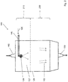
- FIG. 1 The apparatus shown is used to produce a SiO 2 soot body 200.
- a support tube 160 made of aluminum oxide a plurality of arranged in a row Flammhydrolysebrenner 140 is arranged.
- a multiplicity of deposition burners are used, which are reversibly reciprocated for soot deposition in a common burner row along the rotating support, wherein each of the burner flames covers only a partial length of the support tube 160 ,
- the SiO 2 feedstock 105 preferably has more than 95% by weight, preferably more than 98% by weight, in particular more than 99.5% by weight, of the polyalkylsiloxane D4 and is supplied to the reaction zone in gaseous form and thereby by oxidation and / or or hydrolysis and / or pyrolysis to SiO 2 decomposes.
- the reaction zone is, for example, a burner flame or a plasma.
- SiO 2 particles 148 are formed, which are deposited in layers on the deposition surface 160 to form the SiO 2 soot body 200.
- the SiO 2 particles 148 themselves are in the form of agglomerates or aggregates of SiO 2 primary particles with particle sizes in the nanometer range.
- the flame hydrolysis burners 140 are mounted on a common burner block 141 which is reciprocated parallel to the longitudinal axis 161 of the support tube 160 between two inflection points fixed relative to the longitudinal axis 161 and which is displaceable perpendicular thereto as indicated by the directional arrows 142.
- the burners 140 are made of quartz glass; their center distance from each other is 15 cm.
- the flame hydrolysis burners 140 are each assigned a burner flame 143 which represents a reaction zone in the sense of the invention.
- SiO 2 particles are formed and deposited on the cylinder jacket surface of the carrier tube 160 rotating about its longitudinal axis 161, so that a soot body 200 having an outer diameter of 350 mm is built up in layers.
- a temperature of about 1200 ° C. is established on the soot body surface 200.
- the flame hydrolysis burners 140 are each supplied with oxygen and hydrogen as burner gases and as feed for the formation of the SiO 2 particles the SiO 2 feedstock vapor 107.
- the term polyalkylsiloxanes encompasses both polyalkylcyclosiloxanes and their linear homologs.
- the production of the SiO 2 feedstock vapor 107 from more than 95% by weight, preferably more than 98% by weight, in particular more than 99.5% by weight, of the polyalkylsiloxane D4 takes place by means of an evaporator system 120 which contains a reservoir 110 for the liquid mixture a pulsation-free liquid pump 122, a flow meter 123 for liquid, an MFC (m ass f low c ontroller) 124 for the regulated supply of a nitrogen carrier gas stream 152 and a heatable evaporation chamber 125 - includes a spray nozzle 128 - even expansion chamber.
- the reservoir 110, a pump 122 and a spray nozzle 128 are connected to each other by means of metallic lines.
- the reservoir 110 is heated to a temperature of 30-40 ° C - also kept at room temperature - and the liquid supplied by the pump 122 via the flow meter 123 in exact dosage of the spray nozzle 128.
- the SiO 2 feedstock 105 is atomized into fine droplets - also known as SiO 2 droplets - also called atomized -, the SiO 2 droplets having a mean diameter of less than 5 .mu.m, preferably less than 2 .mu.m , exhibit.
- a concentration detector for monitoring the composition of the SiO 2 -Einsatzmaterials 105 and / or the SiO 2 -Einsatzdampfes 107 and / or the SiO 2 droplets be provided in the connecting line between the flow meter 123 and atomizer 128th
- This atomizing nozzle 128 ensures that the liquid SiO 2 feedstock is atomized into fine droplets, the droplets having an average diameter of less than 5 ⁇ m, preferably less than 2 ⁇ m.
- the SiO 2 feedstock 105 and / or the droplets can be fed with a nitrogen carrier gas stream via the MFC 123 at a pressure of 1.5 bar to 5 bar.
- the evaporator 120 has an internal temperature of up to 300 ° C, so that the fine liquid droplets evaporate immediately and the vapor stream is fed to a flow divider and is divided by this heat-insulated flexible media supply lines to the individual Abscheidebrenner 140.
- the carrier gas is heated in a preheater 153.
- the carrier gas is heated to temperatures beyond 200 ° C.
- the flow divider also open a supply line for the fuel gases oxygen and hydrogen and an auxiliary gas (oxygen), in the burner flame 143 between the flow of the feedstock and the flow of fuel gas is used, and counteracts an early mixing.
- the mixture of fuel gases and the SiO 2 feed steam 107 thus takes place only in the hot zone of the burner flame 143.
- a tube of porous SiO 2 soot Sootrohr is obtained.
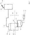
- the Figures 2 and 3 show the system 100 for producing quartz glass, which uses the inventive method.
- an atomization of the SiO 2 feedstock 105 takes place by means of a spray nozzle 128 (for example supersonic atomization).
- the system 100 has for this purpose a storage tank 110 from which the liquid SiO 2 feedstock 105 is pumped by means of a pump 122 into the atomizer nozzle.
- an expansion chamber 125 the transition of the liquid SiO 2 droplets into the gaseous SiO 2 feedstock steam 107 takes place.
- the expansion chamber 125 includes a first zone 210 and a second zone 220.
- the expansion chamber 125 comprises the entire internal volume of the evaporator - that the atomization zone and the heat exchanger zone.
- the atomization of the liquid - also referred to as atomization - and the simultaneous mixing with the highly preheated carrier gas and the transport of the droplets in the second zone 220 of the expansion chamber 125.
- Via a line 130 of SiO flows 2 -Einsatzdampf 107 to the burner 140, where a pyrolytic and / or hydrolytic conversion of the SiO 2 feedstock vapor into SiO 2 particles takes place.
- heating of the SiO 2 feedstock 105 to temperatures well below the boiling point, preferably to room temperature, of the SiO 2 feedstock takes place. This can be done by using a hot oil system or an electric heating element in the walls of the preheater. In order to achieve a uniform heating of the liquid SiO 2 feedstock 105 while avoiding hot areas, it has proved to be advantageous if the storage vessel 110 has a flow channel which is surrounded by hot oil passages. The liquid-to-liquid heat transfer that can be achieved in this way achieves uniform heating of the liquid SiO 2 feedstock 105. This type of uniform heating ensures that there is no chemical reaction due to temperature the polyalkylsiloxanes come.
- the heated liquid SiO 2 feedstock 105 is discharged from the reservoir 110 into the expansion chamber 125 through a feed line 145.
- the expansion chamber 125 - also referred to as the evaporator chamber - defines an internal volume for the free expansion of the SiO 2 feedstock vapor.
- the temperature of the liquid SiO 2 feedstock above the boiling point of the SiO 2 feedstock at the operating pressure of the expansion chamber is increased.
- the boiling point of D4 at atmospheric pressure is about 175 ° C.
- the liquid SiO 2 feedstock from the reservoir 110 flows through the supply line 145 into the interior of the expansion chamber 125, without the SiO 2 feedstock 105 is heated to temperatures greater than 40 ° C. Then, atomization of the SiO 2 feedstock takes place by means of the atomizing nozzle 128. An additional heat input takes place through a carrier gas which, for example, is likewise guided through the atomizer nozzle 128.
- a carrier gas 152 - also referred to as a diluent - in particular nitrogen has proved to be advantageous.
- Other diluents such as argon or helium, may also be used if desired. These are gases which are inert with respect to polyalkylsiloxanes, so that oxidation, polymerization or decomposition reactions between the liquid and the carrier gas, in particular under pressure and higher temperature, and thus an irreproducible change in the composition of the feed avoided become.
- the partial pressure of the liquid SiO 2 feedstock - in this case the droplets of the SiO 2 feedstock - in the expansion chamber 125 is reduced and thus its dew point is lowered.
- the goal is to in that the evaporation of the SiO 2 feedstock material comprises an injection phase in which the feedstock in the first zone is atomized into fine droplets in liquid form and the fine droplets after contact with a hot carrier gas in the second zone - without contact of the liquid core Droplets with walls of the expansion chamber 125 - are completely evaporated quickly and efficiently.
- the Fig. 3 illustrates the evaporation of the invention.
- the heated SiO 2 feedstock 105 is supplied through the supply line 145 to the expansion chamber 125.
- the supply line 145 has a nozzle-like spray nozzle 128.
- the atomizer nozzle 128 - which is preferably an ultrasonic atomizer - the liquid SiO 2 feedstock 105 is atomized into fine droplets, which have a mean diameter of less than 5 .mu.m, preferably less than 2 .mu.m, in particular less than one micron. Particularly preferred results are obtained if the mean particle size is less than 0.5 ⁇ m (d 50 value).
- the median value or d 50 value is the most important parameter as a measure of the average particle size.
- the d 50 value describes the value at which 50 percent of the droplets are finer and the others 50 percent coarser than d 50 .
- a substantial portion of the droplets are transferred to the gas phase.
- a preheated to about 180 ° C to about 300 ° C nitrogen stream is passed through the media line 150 in the expansion chamber 125 and the atomizer 128.
Landscapes
- Chemical & Material Sciences (AREA)
- Engineering & Computer Science (AREA)
- Chemical Kinetics & Catalysis (AREA)
- Manufacturing & Machinery (AREA)
- Materials Engineering (AREA)
- Organic Chemistry (AREA)
- Glass Melting And Manufacturing (AREA)
- Manufacture, Treatment Of Glass Fibers (AREA)
- Silicon Compounds (AREA)
Description
- Die Erfindung betrifft ein Verfahren zur Herstellung von synthetischem Quarzglas, umfassend die Verfahrensschritte:
- (A) Bereitstellen eines flüssigen SiO2-Einsatzmaterials, welches mehr als 70 Gew.% Octamethylcyclotetrasiloxan aufweist,
- (B) Verdampfen des flüssigen SiO2-Einsatzmaterials in einen gasförmigen SiO2 Einsatzdampf, umfassend eine Injektionsphase in einer Expansionskammer, in der das SiO2-Einsatzmaterial in feine Tröpfchen atomisiert wird, wobei die Atomisierung der Tröpfchen in einem Trägergasstrom stattfindet,
- (C) Umsetzen des SiO2-Einsatzdampfes zu SiO2 Partikeln,
- (D) Abscheiden der SiO2 Partikel auf einer Ablagerungsfläche unter Bildung eines SiO2 Sootkörpers,
- (E) Verglasen des SiO2-Sootkörpers unter Bildung des synthetischen Quarzglases.
- Zur Herstellung von synthetischem Quarzglas für kommerzielle Anwendungen werden chlorfreie Einsatzmaterialien erprobt. Als Beispiel seien Monosilane, Alkoxysilane und Siloxane genannt. Eine besonders interessante Gruppe chlorfreier Einsatzmaterialien bilden die Polyalkylsiloxane (auch kurz als "Siloxane" bezeichnet), die beispielsweise aus der
EP 463 045 A1 - Polyalkylsiloxane zeichnen sich durch einen besonders hohen Anteil an Silizium pro Gewichtsanteil aus, was zur Wirtschaftlichkeit ihres Einsatzes bei der Herstellung von synthetischem Quarzglas beiträgt. Wegen der großtechnischen Verfügbarkeit in hoher Reinheit wird derzeit Octamethylcyclotetrasiloxan (OMCTS) bevorzugt eingesetzt. Diese Substanz wird gemäß einer von General Electric Inc. eingeführten Notation auch als "D4" bezeichnet, wobei "D" die Gruppe [(CH3)2Si]-0- repräsentiert.
- Das siliziumhaltige Einsatzmaterial kann dem Verbraucher, wie etwa einem Abscheidebrenner, in flüssiger Form zugeführt werden. In der Regel wird das flüssige Einsatzmaterial aber mittels eines Verdampfers in eine gasförmige oder dampfförmige Phase überführt und dem Verbraucher ein kontinuierlicher Gasstrom zugeführt. Bei den bekannten Verdampfungssystemen wird die zu verdampfende Flüssigkeit mit einer heißen Oberfläche in Kontakt gebracht. Heiße Oberflächen können insbesondere bei organischem Einsatzmaterial zu unvorhergesehenen Veränderungen führen, wie beispielsweise Zersetzungen oder Polymerisationen.
- Aus
US 5 707 415 A ist ein Verfahren zur Herstellung von synthetischem Quarzglas durch Abscheiden von SiO2 Sootmaterial mit OMCTS (Octamethylcyclotetrasiloxan) als SiO2 Einsatzmaterial bekannt. Flüssiges OMCTS wird in einen Verdampfer eingespritzt und zu kleinen Tröpfchen atomisiert. Die Tröpfchen werden anschließend mit Sauerstoff als Trägergas vermischt. Durch eine spezielle Konstruktion des Verdampfers wird die störende Polymerisation des OMCTS bzw. etwaige Ablagerungen der Polymerisate verhindert. - Weiterhin ist aus
US 6 244 575 B1 ein Verdampfer für flüssige Einsatzmaterialien zur Abscheidung von SiO2 Schichten mittels CVD-Verfahren bekannt. Gemäß dieser Druckschrift wird TEOS (Tetraethoxysilan), -nicht OMCTS-, zu feinen Tröpfchen atomisiert, die einen Durchmesser von kleiner 100 µm haben, bevorzugt einen Durchmesser von etwa 20 µm. Die Temperatur des Trägergases hängt u.a. von der Temperatur und der Art des SiO2 Einsatzmaterials ab und liegt bevorzugt im Bereich zwischen 30°C und 250°C. - Die Zersetzungsprodukte beziehungsweise Polymerisate verursachen Ablagerungen in Leitungssystemen und führen letztendlich zu kaum kontrollierbaren und nicht reproduzierbaren Prozessbedingungen. Daraus ergibt sich eine gewisse Variabilität und Unreproduzierbarkeit in der Prozessführung, die zu Fehlern im Partikelbildungsprozess und zu Inhomogenitäten im Sootaufbau führen kann.
- Es ist die Aufgabe der vorliegenden Erfindung, ein Verfahren zur Herstellung von SiO2-Sootkörpern mit hoher Materialhomogenität zu schaffen, bei dem die genannten Nachteile vermieden werden.
- Zur Lösung dieser Aufgabe wird erfindungsgemäß vorgeschlagen, dass die Tröpfchen einem mittleren Durchmesser von weniger als 5 µm aufweisen und während der Atomisierung mit dem Trägergasstrom im Molverhältnis Trägergas/SiO2-Einsatzmaterial >= 1,5 vermischt werden, wobei der Trägergasstrom auf eine Temperatur von mehr als 180°C vorgewärmt ist.
- Beim erfindungsgemäßen Verfahren zur Herstellung von synthetischem Quarzglas ist vorgesehen, dass die feinen Tröpfchen des atomisierten SiO2-Einsatzmaterials einen mittleren Durchmesser von weniger als 5 µm aufweisen, und während der Atomisierung mit dem Trägergasstrom im Molverhältnis Trägergas/SiO2-Einsatzmaterial >= 1,5 vermischt werden, wobei die Atomisierung der Tröpfchen in einem vorgewärmten Trägergasstrom stattfindet, der eine Temperatur von mehr als 180°C aufweist.
- Im Rahmen des erfindungsgemäßen Verfahrens soll ein flüssiges SiO2-Einsatzmaterial in einen SiO2-Einsatzdampf umgewandelt werden. Dabei weist der SiO2-Einsatzdampf vorrangig Polyalkylsiloxane auf, bevorzugt besteht der SiO2-Einsatzdampf aus Polyalkycyclosiloxanen, besonders bevorzugt enthält der SiO2-Einsatzdampf als Hauptkomponente D4. Um homogene Sootkörper zu erlangen muss eine Polymerisation der Polyalkylsiloxane im Rahmen des Verdampfens verhindert werden. Dieses kann mit dem erfindungsgemäßen Verfahren erreicht werden.
- Es wird ein Verdampfungsverfahren gezeigt, welches insbesondere für die kontinuierliche Verdampfung von Polyalkylsiloxanen, insbesondere OMCTS (=D4) über Zeiträume von > 10 h im Batchbetrieb bei hohen Verdampfungsraten von > 20 kg/h eine im Verdampfer annähernd rückstandsfreie Verdampfung ohne die Bildung von störenden polymeren Folgeprodukten ermöglicht. Kritisch dabei ist, dass die zu verdampfende Flüssigkeit bzw. Flüssigkeitströpfchen während der Verdampfung nicht oberhalb ihrer Verdampfungstemperatur erhitzt werden. Dazu soll einerseits eine Zerstäubung der Flüssigkeit in sehr kleine Flüssigkeitstropfen mit einer hohen Oberfläche erreicht werden, um so eine möglichst große Oberfläche für die Wärmeübertragung zu generieren. Andererseits soll eine sehr kurze Verweilzeit des SiO2-Einsatzmaterials im Verdampfungsreaktor (auch als Verdampfer bezeichnet) realisiert werden, um so eine möglichst kurze Reaktionszeit des Siloxans im Verdampfer zu haben. Bei einer sehr kurzen mittleren Verweilzeit im Verdampfungsreaktor (< 2 Sekunden) können unter diesen Bedingungen die Trägergastemperatur und die Oberflächentemperatur im Verdampfungsreaktor auch oberhalb des Siedepunktes der zu verdampfen Flüssigkeit liegen, da die Flüssigkeitströpfchen bei der Phasenumwandlung (flüssig - dampfförmig) gleichzeitig eine Abkühlung erfahren.
- Wesentliche Idee ist es, dass die zu verdampfende Flüssigkeit in feinste Tröpfchen überführt (=als vernebelt oder zerstäubt oder atomisiert bezeichnet) wird und quasi "in situ" während der Atomisierung mit einem stark vorgewärmten Trägergasstrom mit einer Temperatur von mehr als 180°C, insbesondere mehr als 230°C im Molverhältnis Trägergas/Siloxan >= 1,5 (bevorzugt im Molverhältnis von mehr als 2,5, insbesondere mehr als 3) vermischt werden. Die feinsten Flüssigkeitstropfen (< 10 micron) nehmen die Wärme vom vorgeheitzten Trägergas über die äußere Oberfläche auf und eine erste Schicht der äußeren Oberfläche des Tröpfchens verdampft und bildet um das Tröpfchen einen dünnen Dampffilm aus. Die von einem Dampffilm umgebenen Flüssigkeitströpfchen werden direkt in einen Verdampfungsreaktor transportiert und dort komplett verdampft. Dadurch dass die Flüssigkeitströpfchen von einem dünnen Dampffilm mit hoher Dampfkonzentration umgeben sind, kann die flüssige Phase des Flüssigkeitströpfchen (= innere, noch unverdampfte Bereich des Tröpfchens) zu keiner Zeit direkten Kontakt zur Innenwandung des Verdampfer des Wärmetauschers bekommen. Damit wird verhindert, dass die flüssige Phase des Flüssigkeitstropfens in direkten Kontakt zur Metalloberfläche des Verdampfungsreaktors kommt.
- In einer vorteilhaften Ausgestaltung wird das erfindungsgemäße Verfahren in einem Verdampfer umgesetzt. Dieser Verdampfer - auch als Verdampfungskammer bezeichnet - weist zwei Zonen auf. Die erste Zone ist die Atomisierungszone, in welcher das flüssige SiO2-Einsatzmaterial in feine Tropfen überführt wird. Dieser auch als Atomisierung bezeichnete Vorgang umfasst ein Zerstäuben der Flüssigkeit in Tropfen, deren Durchmesser kleiner als 2 µm (1 µm = 1 micron), bevorzugt kleiner als 0,5 µm ist. Weiterhin findet in dieser ersten Zone ein Vermischen der Tropfen mit einem Trägergas statt. Die Besonderheit des erfindungsgemäßen Verfahrens besteht darin, dass das Trägergas vorgeheizt ist. Im Stand der Technik ist es bekannt, Trägergas zu nutzen, welches Zimmertemperatur (ca. 10°C bis ca. 40°C) aufweist. Abweichend davon wird im erfindungsgemäßen Verfahren ein stark aufgeheiztes Trägergas mit einer Temperatur von mehr als 180°C, bevorzugt mehr als 230°C genutzt, um die Atomisierung zu unterstützen. Folglich dient das Trägergas zum einen als Träger der Tropfen an sich. Gleichzeitig setzt das Trägergas den Taupunkt des eingesetzten SiO2-Einsatzmaterials herab und sorgt so für einen schnelleren Übergang aus der Flüssig- in die Gas-Phase. Weiterhin dient das stark aufgeheizte Trägergas dazu, in einem kurzen Zeitintervall einen ersten Energieeintrag in das flüssige SiO2-Einsatzmaterial sicherzustellen. Die Nutzung von sehr stark erhitztem Trägergas hat gegenüber der im Stand der Technik bekannten Nutzung von kaltem Trägergas eine Vielzahl von Vorteilen. Zum einen bedarf es keiner Vorheizung des flüssigen Si02-Einsatzmaterials. Dieses kann direkt und kalt - als nicht aufgeheizt - aus einem Vorratsbehälter entnommen werden. Dadurch ist es möglich, Flüssigkeitsdurchflussmesser zu nutzen, um die dem Verdampfer zugefügte Menge des SiO2-Einsatzmaterials zu bestimmen. Solche Art Flüssigkeitsdurchflussmesser arbeiten maximal bis Temperaturen von 80°C. Durch die Nutzung von flüssigem Si02-Einsatzmaterial, welches maximal eine Temperatur von maximal 60°C, bevorzugt weniger als 50°C besonders bevorzugt weniger als 40°C aufweist, können die dem Verdampfer zugefügten flüssigen Mengen präzise mit dem Flüssigkeitsdurchflussmesser bestimmt werden. Dieses ist günstig für reproduzierbare Prozessbedingungen. Die so entstehenden Gele können bei solcher Art hohen Durchsätzen, wie sie mit dem hier offenbarten Verfahren bewerkstelligt werden sollen, zu Verstopfungen bzw. Quersschnittsverengungen der Zuleitungen etc. führen. Dieses wiederum beeinflusst die Druck- und Strömungsverhälntisse in der Dampfleitung. Da im hier offenbarten Verfahren das SiO2-Einsatzmaterial - insbesondere die Polyalkylsiloxane - in der Zuleitung im flüssigen Zustand auf bevorzugt weniger als 40°C aufgeheizt werden, besonders bevorzugt auf Raumtemperatur gehalten werden, findet keinerlei Polymerisation mehr statt. Folglich ergeben sich keine Verstopfungen der Zuleitungen und/oder am Flüssigkeitsdurchflussmesser.
- Nachdem in der ersten Zone des Verdampfers eine Atomisierung des SiO2-Einsatzmaterials und eine Vermischung mit dem heißen Trägergas stattgefunden hat, strömt dieses Gemisch in die zweite Zone des Verdampfers ein. Die zweite Zone - auch als Wärmetauscherzone und/oder Wärmetauscher bezeichnet - dient zur weiteren Energiezufuhr und damit zur weiteren Verdampfung. Durch die Nutzung eines heißen Trägergases ist die in der zweiten Zone benötigte Energiezufuhr geringer als im Stand der Technik. Darüber hinaus dient die bei der schlagartigen Verdampfung in dem Atomisierer - auch als Atomisator bezeichnet - entstehende Dampfschutzschicht um das Tröpfchen als eine Art Schild gegen einen direkten Kontakt der Flüssigkeit im Tröpfchen mit der Wandung und/oder innerer Kanäle der zweiten Zone. Dadurch wird eine Polymerisation des flüssigen SiO2-Einsatzmaterials in den Tröpfchen verhindert.
- Die Dampfschutzschicht ummantelt das flüssige SiO2-Einsatzmaterial in dem Tröpfchen. Es wirkt als eine Abschirmung der Flüssigkeit gegenüber äußeren Einflüssen. Vorteilhafterweise hat sich herausgestellt, dass Energieeinträge durch diese Dampfschicht besonders schnell in das flüssige SiO2-Einsatzmaterial eindringen können. Folglich unterstützt die Dampfschutzschicht das Verdampfen des flüssigen SiO2-Einsatzmaterials in dem Tröpfchen. Diese Erkenntnis begründet, warum bei einer Annäherung des Tröpfchens an eine aufgeheizte Wandung in der zweiten Zone kein direkter Kontakt zwischen dem flüssigen Si02-Material und der zweiten Zone auftritt. Vielmehr wird die in der zweiten Zone abgestrahlte Wärme von der Dampfschutzschicht aufgenommen und auf das flüssige Si02-Einsatzmaterial derart konzentriert, dass eine schnelle Verdampfung stattfindet. Somit findet kein direkter Kontakt zwischen dem flüssigen SiO2-Einsatzmaterial und Wänden oder Kanälen der zweiten Zone statt. Dadurch wird die Neigung der Polyalkylsiloxane zur Polymerisation deutlich reduziert. Insgesamt wird also die Innenfläche des Verdampfers sowie auch alle ableitenden Kanäle aus dem Verdampfer heraus deutlich weniger als im Stand der Technik mit polymerisierten Resten der Polyalkylsiloxane beaufschlagt.
- Um die Chancen eines direkten Kontaktes des flüssigen SiO2-Einsatzmaterials mit Innenwänden oder Kanälen des Wärmetauschers - also der zweiten Zone - zu reduzieren, hat es sich als vorteilhaft erwiesen, wenn die Zeitspanne, die vom Einspeisen des flüssigen SiO2-Einsatzmaterials in den Atomisator bis zum Austritt des gasförmigen SiO2-Einsatzdampfes möglichst kurz ist. Vorteilhafterweise beträgt die mittlere Verweilzeit weniger als eine Sekunde.
- So kann die Oberflächentemperatur des Verdampfungsreaktors in der zweiten Zone mindestens 10°C oberhalb des Taupunktes des Gasgemisches liegen. Durch den schützenden Dampffilm um das Tröpfchen herum wird ein direkter Wandkontakt der flüssigen Phase und damit auch eine Überhitzung der flüssigen Phase vermieden. Damit wird das Risiko für eine partielle Polymerisation des Siloxans in der zweiten Zone des Verdampfers vermieden.
- Weiterhin kann die mittlere Verweilzeit der Dampfmoleküle im Verdampfervolumen des Verdampfers weniger als 2 Sekunden, bevorzugt weniger als 1 Sekunden, noch bevorzugter weniger als 0,5 Sekunde betragen.
- Eine vorteilhafte Ausgestaltung des Verfahrens zeichnet sich dadurch aus, dass der Verdampfer eine erste Zone und eine zweite Zone aufweist. Dabei weist die erste Zone die Zerstäubungseinheit und die zweite Zone den Wärmetauscher auf.
- Eine vorteilhafte Ausgestaltung des Verfahrens zeichnet sich dadurch aus, dass in der Zerstäubungseinheit (Atomisierungseinheit) aus dem flüssigen SiO2-Einsatzmaterial feine Tröpfchen generiert werden (z. B. Düse, Ultraschallzerstäubung) mit einer mittleren Tröpfchengröße von weniger als 2 micron.
- Eine vorteilhafte Ausgestaltung des Verfahrens zeichnet sich dadurch aus, dass das Trägergas insbesondere Stickstoff oder Argon oder Helium aufweist und eine Temperatur von mehr als 200°C, besonders bevorzugt eine Temperatur von mehr als 230°C bis maximal 350°C aufweist.
- Eine vorteilhafte Ausgestaltung des Verfahrens zeichnet sich dadurch aus, dass sich durch den Energieeintrag des Trägergases um die atomisierten Tröpfchen eine über der Oberfläche des Tröpfchens partielle Tröpfchenverdampfung einsetzt und sich so um die Oberfläche des Tröpfches ein Dampffilm ausbildet.
- Eine vorteilhafte Ausgestaltung des Verfahrens zeichnet sich dadurch aus, dass die vom dem Dampffilm umgebenen flüssige Phase des Tröpfchens aufgrund des Dampffilmes keinen direkten Kontakt zu beheizten Elementen in der zweiten Zone und/oder der Wärmetauschereinheit erfahren, so dass eine Benetzung von Flüssigkeitstropfen an den Wänden innerhalb des Vedampfers ausgeschlossen wird.
- Eine vorteilhafte Ausgestaltung des Verfahrens zeichnet sich dadurch aus, dass mindestens 7,5% der eingetragenen Energie durch das Trägergas zur Verdampfung des Siloxans beiträgt.
- Eine vorteilhafte Ausgestaltung des Verfahrens zeichnet sich dadurch aus, dass die Oberflächentemperatur des Wärmetauschers oberhalb des Siedepunktes des zuverdampfenden Siloxans liegt.
- Eine vorteilhafte Ausgestaltung des Verfahrens zeichnet sich dadurch aus, dass die mittlere Verweilzeit des Siloxans im Verdampfer < 5 Sekunden, bevorzugt < 1 Sekunde beträgt.
- Eine vorteilhafte Ausgestaltung des Verfahrens zeichnet sich dadurch aus, dass das Verhältnis von generiertem Dampfvolumen pro Sekunde (OMCTS + Trägergas bei der Dampfaustrittstemperatur) und innerem Volumen der Verdampfungskammer > 0,5, bevorzugt > 1 beträgt.
- Der Verdampfer kann sowohl senkrecht als auch horizontal ausgerichtet sein. Das Prinzip des Verdampfers ist es, aufgrund der sehr kleinen Tröpfchengröße in Kombination mit eine hohen Wärmeübertragung, hohen Strömungsgeschwindigkeiten als auch kurzen Verweilzeiten eine unmittelbare Untersättigung des Dampfdruckes der Flüssigkeit (Überschreitung des Taupunktes) zu erreichen. Dadurch bilden sich keine störenden Kondensatröpfchen mehr aus. Eine bevorzugte Ausrichtung des Verdampfers ist daher nicht erforderlich.
- Weitere Vorteile, Merkmale und Einzelheiten der Erfindung ergeben sich aus der nachfolgenden Beschreibung, in der unter Bezugnahme auf die Zeichnungen ein Ausführungsbeispiel der Erfindung im Einzelnen beschrieben sind. Dabei können die in den Ansprüchen und der Beschreibung erwähnten Merkmale jeweils einzeln für sich oder in beliebiger Kombination erfindungswesentlich sein. Es zeigen:
- Figur 1
- eine Vorrichtung zur Durchführung des erfindungsgemäßen Verfahrens zur Herstellung eines SiO2-Sootkörpers in schematischer Darstellung,
- Figur 2
- ein schematisches Diagramm der verschiedenen Elemente des erfindungsgemäßen Quarzglasherstellungssystems und
- Figur 3
- eine weitere schematische Darstellung einer Verdampfungskammer.
- Der Ausgangspunkt des erfindungsgemäßen Verfahrens ist dabei die Bildung eines Gasstromes aus einem SiO2-Einsatzdampf 107, der als Hauptkomponente D4 enthält. Der Gasstrom wird einer Reaktionszone zugeführt, in der der SiO2-Einsatzdampf unter Bildung amorpher SiO2-Partikel durch Pyrolyse, Oxidation oder Hydrolyse zu SiO2 umgesetzt wird. Das sich anschließende Abscheiden der amorphen SiO2-Partikel auf einer Ablagerungsfläche 160 führt zur Bildung eines porösen SiO2-Sootkörpers 200, der durch Verglasung ein synthetisches Quarzglas bildet. Um dabei die Herstellung von großvolumigen zylinderförmigen Sootkörpern 200 mit Außendurchmessern von mehr als 300 mm mit verbesserter Materialhomogenität zu ermöglichen, offenbart die Erfindung, dass das Verdampfen des erhitzten SiO2-Einsatzmaterials eine Injektionsphase in einer Expansionskammer umfasst, in der das SiO2-Einsatzmaterial - insbesondere in flüssiger Form - in feine Tröpfchen zerstäubt wird, wobei die Tröpfchen einem mittleren Durchmesser von weniger als 5 µm, vorzugsweise weniger als 2 µm, aufweisen.
- Die in
Figur 1 dargestellte Vorrichtung dient zur Herstellung eines SiO2-Sootkörpers 200. Entlang eines Trägerrohres 160 aus Aluminiumoxid ist eine Vielzahl in einer Reihe angeordneter Flammhydrolysebrenner 140 angeordnet. Bei einer auf höhere Produktivität abzielenden Verfahrensabwandlung wird anstelle nur eines Brenners 140 eine Vielzahl von Abscheidebrennern eingesetzt, die zur Soot-Abscheidung in einer gemeinsamen Brennerreihe entlang des rotierenden Trägers reversierend hin- und herbewegt werden, wobei jede der Brennerflammen nur eine Teillänge des Trägerrohres 160 überstreicht. - Das SiO2-Einsatzmaterial 105 weist vorzugsweise mehr als 95 Gew.%, bevorzugt mehr als 98 Gew.%, insbesondere mehr als 99,5 Gew.% des Polyalkylsiloxanes D4 auf und wird der Reaktionszone in gasförmiger Form zugeführt und dabei durch Oxidation und/oder Hydrolyse und/oder Pyrolyse zu SiO2 zersetzt. Die Reaktionszone ist beispielsweise eine Brennerflamme oder ein Plasma. In der Reaktionszone entstehen SiO2-Partikel 148, die unter Bildung des SiO2-Sootkörpers 200 auf der Ablagerungsfläche 160 schichtweise niedergeschlagen werden. Die SiO2-Partikel 148 selbst liegen in Form von Agglomeraten oder Aggregaten von SiO2-Primärpartikeln mit Partikelgrößen im Nanometerbereich vor.
- Die Flammhydrolysebrenner 140 sind auf einem gemeinsamen Brennerblock 141 montiert, der parallel zur Längsachse 161 des Trägerrohrs 160 zwischen zwei, in Bezug auf die Längsachse 161 ortsfesten Wendepunkten hin- und herbewegt wird und der senkrecht dazu verschiebbar ist, wie dies die Richtungspfeile 142 andeuten. Die Brenner 140 bestehen aus Quarzglas; ihr Mittenabstand zueinander beträgt 15 cm.
- Den Flammhydrolysebrennern 140 ist jeweils eine Brennerflamme 143 zugeordnet, die eine Reaktionszone im Sinne der Erfindung darstellt. In ihr werden SiO2-Partikel gebildet und auf der Zylindermantelfläche des um seine Längsachse 161 rotierenden Trägerrohrs 160 abgeschieden, so dass schichtweise ein Sootkörper 200 mit einem Außendurchmesser von 350 mm aufgebaut wird. Während des Abscheideprozesses stellt sich auf der Sootkörperoberfläche 200 eine Temperatur von etwa 1200°C ein. Den Flammhydrolysebrennern 140 werden jeweils als Brennergase Sauerstoff und Wasserstoff zugeführt sowie als Einsatzmaterial für die Bildung der SiO2-Partikel der SiO2-Einsatzdampf 107. Im Rahmen der Erfindung umfasst der Begriff Polyalkylsiloxane sowohl Polyalkylcyclosiloxane als auch deren lineare Homologe.
- Die Herstellung des SiO2-Einsatzdampfes 107 aus mehr als 95 Gew.%, bevorzugt mehr als 98 Gew.%, insbesondere mehr als 99,5 Gew.% des Polyalkylsiloxanes D4 erfolgt mittels eines Verdampfersystems 120, das einen Vorratsbehälter 110 für das flüssige Gemisch, eine pulsationsfreie Flüssigkeitspumpe 122, ein Durchflussmessgerät 123 für Flüssigkeit, einen MFC (mass flow controller) 124 für die geregelte Zufuhr eines Stickstoff-Trägergasstroms 152 und eine beheizbare Verdampfungskammer 125 - auch Expansionskammer - mit einer Zerstäuberdüse 128 umfasst. Der Vorratsbehälter 110, eine Pumpe 122 und eine Zerstäuberdüse 128 sind mittels metallischer Leitungen miteinander verbunden. Der Vorratsbehälter 110 wird auf eine Temperatur von 30-40°C erwärmt - auch auf Raumtemperatur gehalten - und die Flüssigkeit mittels der Pumpe 122 über das Durchflussmessgerät 123 in exakter Dosierung der Zerstäuberdüse 128 zugeführt. In und mittels der Zerstäuberdüse wird das SiO2-Einsatzmaterial 105 in feine Tröpfchen - auch als SiO2-Tröpfchen bezeichnet- zerstäubt - auch als atomisiert bezeichnet - , wobei die SiO2-Tröpfchen einen mittleren Durchmesser von weniger als 5 µm, vorzugsweise weniger als 2 µm, aufweisen. Dabei kann in der Verbindungsleitung zwischen Durchflussmessgerät 123 und Zerstäuber 128 ein Konzentrationsdetektor zur Überwachung der Zusammensetzung des SiO2-Einsatzmaterials 105 und/oder des SiO2-Einsatzdampfes 107 und/oder der SiO2-Tröpfchen vorgesehen sein.
- Bei dem Zerstäuber 128 - auch als Zerstäuberdüse oder Atomisierer bezeichnet - kann es sich um einen Ultraschallzerstäuber oder einen Überschallzerstäuber ("supersonic") handeln. Diese Zerstäuberdüse 128 stellt sicher, dass das flüssige SiO2-Einsatzmaterial in feine Tröpfchen zerstäubt wird, wobei die Tröpfchen einem mittleren Durchmesser von weniger als 5 µm, vorzugsweise weniger als 2 µm, aufweisen. Je nach Ausgestaltung kann dem SiO2-Einsatzmaterials 105 und/oder den Tröpfen ein Stickstoff-Trägergasstrom über den MFC 123 mit einem Druck von 1,5 bar bis 5 bar zugeführt werden.
- In einer vorteilhaften Ausführungsform zerstäubt die Zerstäuberdüse 128 zusammen mit einem separat eingespeistem und auf mehr als 200 °C vorgewärmten Trägergas das SiO2-Einsatzmaterials 105 in feine Tröpfchen mit einem maximalen Durchmesser von 5 µm und schmaler Tröpfchengrößenverteilung mit einem mittleren Durchmesser (d50-Wert) von 0,9 µm, und sprüht unmittelbar danach diese Tröpfchen in der Injektionsphase in die nachgeschaltete Wärmetauscherzone 220 des Verdampfers 120 ein. Der Verdampfer 120 hat eine Innentemperatur von bis zu 300°C, so dass die feinen Flüssigkeitstöpfchen unmittelbar verdampfen und der Dampfstrom einem Flussteiler zugeführt und von diesem über wärmeisolierte flexible Medienzufuhrleitungen auf die einzelnen Abscheidebrenner 140 aufgeteilt wird. Das Trägergas wird in einem Vorheizer 153 aufgeheizt. Dabei wird das Trägergas auf Temperaturen jenseits von 200°C erwärmt.
- In den Flussteiler münden auch eine Zufuhrleitung für die Brenngase Sauerstoff und Wasserstoff sowie eines Hilfsgases (Sauerstoff), das in der Brennerflamme 143 zwischen dem Strom des Einsatzmaterials und dem Strom des Brenngases eingesetzt wird, und das einer frühzeitigen Durchmischung entgegenwirkt. Die Mischung von Brenngasen und dem SiO2-Einsatzdampf 107 erfolgt somit erst in der heißen Zone der Brennerflamme 143. Nach Abschluss des Abscheideprozesses wird ein Rohr aus porösem SiO2-Soot (Sootrohr) erhalten.
- Die
Figuren 2 und3 zeigen das System 100 zur Herstellung von Quarzglas, welches das erfindungsgemäße Verfahren nutzt. Dabei findet eine die Zerstäubung des SiO2-Einsatzmaterials 105 mittels einer Zerstäuberdüse 128 statt (z. B. Überschallzerstäubung). Das System 100 weist dazu einen Vorratstank 110 auf, aus dem das flüssige SiO2-Einsatzmaterial 105 mittels einer Pumpe 122 in die Zerstäuberdüse gepumpt wird. In einer Expansionskammer 125 findet der Übergang der flüssigen SiO2-Tröpfchen in den gasförmigen SiO2-Einsatzdampf 107 statt. Dabei umfasst definitionsgemäß die Expansionskammer 125 eine erste Zone 210 und eine zweite Zone 220. Somit umfasst die Expansionskammer 125 das gesamte innere Volumen des Verdampfers - also der Atomisierungszone und der Wärmetauscherzone. In der ersten Zone 210 der Expansionskammer 125 findet das Zerstäuben der Flüssigkeit - auch als Atomisieren bezeichnet - und das gleichzeitige Vermischen mit dem stark vorgewärmten Trägergas statt sowie der Transport der Tröpfchen in die zweite Zone 220 der Expansionskammer 125. Über eine Leitung 130 strömt der SiO2-Einsatzdampf 107 zu dem Brenner 140, wo eine pyrolytische und/oder hydrolytische Umsetzung des SiO2-Einsatzdampfes in SiO2-Partikel erfolgt. - Innerhalb des Vorratsbehälters 110 findet eine Erwärmung des SiO2-Einsatzmaterials 105 auf Temperaturen deutlich unterhalb des Siedepunkts, vorzugsweise auf Raumtemperatur, des SiO2-Einsatzmaterials statt. Dieses kann durch die Verwendung eines Heißölsystems oder eines elektrischen Heizelementes in den Wänden der Vorheizeinrichtung erfolgen. Um eine gleichmäßige Aufheizung des flüssigen SiO2-Einsatzmaterials 105 unter Vermeidung heißer Bereiche zu erzielen, hat es sich als vorteilhaft erwiesen, wenn der Vorratsbehälters 110 einen Strömungskanal aufweist, welcher von Heißölkanälen umgeben ist. Der so realisierbare flüssig-zu-flüssig Hitzetransfer erzielt eine gleichmäßige Erhitzung des flüssigen SiO2-Einsatzmateriales 105. Diese Art der gleichmäßigen Erwärmung stellt sicher, dass es nicht zu temperaturbedingten chemischen Umsetzung der Polyalkylsiloxane kommt. Das erhitzte flüssige SiO2-Einsatzmaterial 105 wird von dem Vorratsbehälter 110 in die Expansionskammer 125 durch eine Zuführungsleitung 145 abgegeben.
- Die Expansionskammer 125 - auch als Verdampferkammer bezeichnet - definiert ein Innenvolumen für die freie Ausdehnung des SiO2-Einsatzdampfes. Um eine gleichmäßige Verdampfung der SiO2-Tröpfchen in den gasförmigen Einsatzdampf zu erzielen, hat es sich nicht als vorteilhaft erwiesen, wenn in dem Vorratsbehälter 110 die Temperatur des flüssigen SiO2-Einsatzmaterials über den Siedepunkt des SiO2-Einsatzmaterials bei dem Betriebsdruck der Expansionskammer erhöht wird. Eine bevorzugte Betriebstemperatur für den Vorratsbehälter 110 liegt unterhalb 40°C, idealerweise bei Raumtemperatur (=22°C). Der Siedepunkt von D4 bei Atmosphärendruck beträgt ungefähr 175 °C. Somit wird vermieden, dass sich Gele oder Ablagerungen durch eine Polymerisation des SiO2-Einsatzmaterials bilden.
- Wie die
Figur 3 verdeutlicht, fließt das flüssige SiO2-Einsatzmaterial aus dem Vorratsbehälter 110 durch die Zuführungsleitung 145 in den Innenraum der Expansionskammer 125, ohne dass das SiO2-Einsatzmaterial 105 auf Temperaturen von mehr als 40°C erhitzt wird. Dann findet eine Zerstäubung des SiO2-Einsatzmaterials mittels der Zerstäuberdüse 128 statt. Ein zusätzlicher Wärmeeintrag erfolgt durch ein Trägergas, welches beispielsweise ebenfalls durch die Zerstäuberdüse 128 geführt wird. - Als Trägergas 152 - auch als Verdünnungsmittel bezeichnet - hat sich insbesondere Stickstoff als vorteilhaft erwiesen. Andere Verdünnungsmittel, wie beispielsweise Argon oder Helium, können ebenfalls verwendet werden, wenn dieses erwünscht ist. Hierbei handelt es sich um Gase, die sich in Bezug auf Polyalkylsiloxane inert verhalten, so dass Oxidations-, Polymerisations- oder Zersetzungsreaktionen zwischen der Flüssigkeit und dem Trägergas, insbesondere unter Druck und höherer Temperatur, und damit eine nicht reproduzierbare Veränderung der Zusammensetzung des Einsatzmaterials vermieden werden. Durch das Hinzuführen des Verdünnungsmittels wird der Partialdruck des flüssigen SiO2-Einsatzmaterials - hier der Tröpfchen des SiO2-Einsatzmaterials - in der Expansionskammer 125 vermindert und so dessen Taupunkt erniedrigt. Ziel ist es dabei, dass das Verdampfen des SiO2-Einsatzmaterials eine Injektionsphase umfasst, in der das Einsatzmaterial in der ersten Zone in flüssiger Form in feine Tröpfchen zerstäubt wird und die feinen Tröpfchen nach dem Kontakt mit einem heißen Trägergas in der zweiten Zone - ohne Kontakt des flüssigen Kerns der Tröpfchen mit Wandungen der Expansionskammer 125 - schnell und effizient vollständig verdampft werden.
- Die
Fig. 3 verdeutlicht die erfindungsgemäße Verdampfung. Das aufgeheizte SiO2-Einsatzmaterial 105 wird durch die Zuführungsleitung 145 der Expansionskammer 125 zugeführt. Am Ende der Zuführungsleitung 145 im Inneren der Expansionskammer 125 weist die Zuführungsleitung 145 einen düsenartigen Zerstäuberdüse 128 auf. Mittels der Zerstäuberdüse 128 - die vorzugsweise ein Ultraschallzerstäuber ist - wird das flüssige SiO2-Einsatzmaterial 105 in feine Tropfen zerstäubt, welche einen mittleren Durchmesser von weniger als 5 µm, bevorzugt weniger als 2 µm, insbesondere weniger als einem µm aufweisen. Besonders bevorzugte Ergebnisse ergeben sich, wenn die mittlere Teilchengröße kleiner 0,5 µm beträgt (d50-Wert). Der Medianwert oder d50-Wert ist dabei als Maß für die mittlere Teilchengröße die wichtigste Kenngröße. Der d50-Wert beschreibt jenen Wert, bei dem 50 Prozent der Tröpfchen feiner sind und die anderen 50% grober sind als d50. - Durch den Druckabfall, der beim Austritt aus der Zerstäuberdüse 128 auftritt wird ein wesentlicher Teil der Tröpfchen in die Gasphase überführt. Zusätzlich wird durch die Medienleitung 150 ein auf ca. 180°C bis ca. 300°C vorgewärmter Stickstoffstrom in die Expansionskammer 125 und die Zerstäuberdüse 128 geleitet.
- Es ist nicht vorgesehen, dass sich Teile des flüssigen SiO2-Einsatmaterials 105 - die Tröpfchen- an den Wänden der Expansionskammer 125 niederschlagen und/oder dort thermisch verdampft werden. Durch die Leitung 130 findet der Abfluss des gasförmigen SiO2-Einsatzdampfes 107 zu dem Brenner 140 statt. Im Brenner 140 wird der SiO2-Einsatzdampfes 107 durch Pyrolyse, Oxidation oder Hydrolyse zu SiO2-Partikel 148 - auch als SiO2 oder Soot oder SiO2-Soot bezeichnet - umgesetzt.
-
- 100
- System
- 105
- SiO2-Einsatzmaterial
- 107
- SiO2-Einsatzdampf
- 110
- Vorratstank / Vorratsbehälter
- 117
- Ablauf
- 120
- Verdampfer / Verdampfersystem
- 122
- Flüssigkeitspumpe
- 123
- Durchflussmessgerät
- 124
- MFC (mass flow controller)
- 125
- Expanionskammer / Verdampfungskammer
- 126
- Leitung
- 127
- Flussteiler
- 128
- Zerstäuberdüse
- 130
- Leitung
- 140
- Brenner / Flammhydrolysebrenner
- 141
- Brennerblock
- 142
- Bewegung von 140
- 143
- Brennerflamme
- 145
- Zuführungsleitung
- 148
- SiO2-Soot
- 150
- Medienleitung
- 151
- Vorratsbehälter
- 152
- Verdünnungsmittel
- 153
- Vorheitzer
- 160
- Ablagerungsfläche / Trägerrohr
- 161
- Längsachse von 160
- 200
- Sootkörper
Claims (2)
- Verfahren zur Herstellung von synthetischem Quarzglas, umfassend die Verfahrensschritte:(A) Bereitstellen eines flüssigen SiO2-Einsatzmaterials (105), welches mehr als 70 Gew.% Octamethylcyclotetrasiloxan aufweist,(B) Verdampfen des flüssigen SiO2-Einsatzmaterials (105) in einen gasförmigen SiO2 Einsatzdampf (107), umfassend eine Injektionsphase in einer Expansionskammer (125), in der das SiO2-Einsatzmaterial (105) in feine Tröpfchen atomisiert wird, wobei die Atomisierung der Tröpfchen in einem Trägergasstrom stattfindet,(C) Umsetzen des SiO2-Einsatzdampfes (107) zu SiO2 Partikeln,(D) Abscheiden der SiO2 Partikel auf einer Ablagerungsfläche (160) unter Bildung eines SiO2 Sootkörpers (200),(E) Verglasen des SiO2-Sootkörpers unter Bildung des synthetischen Quarzglases,dadurch gekennzeichnet, dass die Tröpfchen einem mittleren Durchmesser von weniger als 5 µm aufweisen und während der Atomisierung mit dem Trägergasstrom im Molverhältnis Trägergas/SiO2-Einsatzmaterial >= 1,5 vermischt werden, wobei der Trägergasstrom auf eine Temperatur von mehr als 180°C vorgewärmt ist.
- Verfahren nach Anspruch 1, dadurch gekennzeichnet, dass das SiO2-Einsatzmaterial (105) in feine Tröpfchen atomisiert wird, wobei die Tröpfchen einem mittleren Durchmesser von weniger als 2 µm aufweisen.
Applications Claiming Priority (2)
| Application Number | Priority Date | Filing Date | Title |
|---|---|---|---|
| DE102011121190A DE102011121190A1 (de) | 2011-12-16 | 2011-12-16 | OMCTS-Verdampfungsverfahren |
| PCT/EP2012/075346 WO2013087751A1 (de) | 2011-12-16 | 2012-12-13 | Verfahren zur herstellung von synthetischem quarzglas |
Publications (2)
| Publication Number | Publication Date |
|---|---|
| EP2791069A1 EP2791069A1 (de) | 2014-10-22 |
| EP2791069B1 true EP2791069B1 (de) | 2017-08-02 |
Family
ID=47435939
Family Applications (1)
| Application Number | Title | Priority Date | Filing Date |
|---|---|---|---|
| EP12806426.8A Active EP2791069B1 (de) | 2011-12-16 | 2012-12-13 | Verfahren zur herstellung von synthetischem quarzglas |
Country Status (8)
| Country | Link |
|---|---|
| US (1) | US9481597B2 (de) |
| EP (1) | EP2791069B1 (de) |
| JP (1) | JP6138145B2 (de) |
| KR (1) | KR101614339B1 (de) |
| CN (1) | CN103987667B (de) |
| DE (1) | DE102011121190A1 (de) |
| IN (1) | IN2014CN04381A (de) |
| WO (1) | WO2013087751A1 (de) |
Families Citing this family (18)
| Publication number | Priority date | Publication date | Assignee | Title |
|---|---|---|---|---|
| JP6236866B2 (ja) * | 2013-05-15 | 2017-11-29 | 住友電気工業株式会社 | ガラス微粒子堆積体の製造方法およびガラス微粒子堆積体製造用バーナー |
| DE102013209673B3 (de) | 2013-05-24 | 2014-05-22 | Heraeus Quarzglas Gmbh & Co. Kg | Verfahren und Verdampfer zur Herstellung von synthetischem Quarzglas |
| EP3034476A1 (de) | 2014-12-16 | 2016-06-22 | Heraeus Quarzglas GmbH & Co. KG | Verfahren zur herstellung von synthetischem quarzglas unter verwendung einer reinigungsvorrichtung |
| EP3059212A1 (de) | 2015-02-18 | 2016-08-24 | Heraeus Quarzglas GmbH & Co. KG | Verfahren und vorrichtung zur herstellung von quarzglas aus einer polymerisierbaren polyalkylsiloxanverbindung mit membranfilter als reinigungsvorrichtung |
| EP3434653A1 (de) | 2017-07-24 | 2019-01-30 | Heraeus Quarzglas GmbH & Co. KG | Einsatz von einer polyalkylsiloxanverbindung mit geringem siloxanolgehalt für die herstellung von synthetischem quarzglas |
| JP6978991B2 (ja) | 2018-08-23 | 2021-12-08 | 信越化学工業株式会社 | 光ファイバ用多孔質ガラス母材の製造方法および製造装置 |
| JP7463967B2 (ja) * | 2018-12-04 | 2024-04-09 | 住友電気工業株式会社 | ガラス微粒子堆積体の製造装置及び製造方法 |
| CN109373196A (zh) * | 2018-12-05 | 2019-02-22 | 上海正帆科技股份有限公司 | 一种八甲基环四硅氧烷的输送及汽化系统和方法 |
| JP7058627B2 (ja) * | 2019-06-11 | 2022-04-22 | 信越化学工業株式会社 | 光ファイバ用多孔質ガラス母材の製造装置および製造方法 |
| CN115485246A (zh) | 2020-05-01 | 2022-12-16 | 信越化学工业株式会社 | 多孔玻璃基材制造装置、多孔玻璃基材的制造方法及光纤用玻璃基材的制造方法 |
| EP3950610A1 (de) | 2020-08-06 | 2022-02-09 | Heraeus Quarzglas GmbH & Co. KG | Alternative fluorierungsmittel ii: fluosil und sootaufbau |
| EP3950611A1 (de) | 2020-08-06 | 2022-02-09 | Heraeus Quarzglas GmbH & Co. KG | Alternative fluorierungsmittel zur herstellung von fluoriertem quarzglas |
| JP7428632B2 (ja) | 2020-12-14 | 2024-02-06 | 信越化学工業株式会社 | 多孔質ガラス母材の製造方法及び製造装置 |
| EP4015468A1 (de) | 2020-12-16 | 2022-06-22 | Heraeus Quarzglas GmbH & Co. KG | Verfahren zur herstellung von synthetischem quarzglas |
| EP4015467A1 (de) | 2020-12-16 | 2022-06-22 | Heraeus Quarzglas GmbH & Co. KG | Verfahren zur herstellung von synthetischem quarzglas |
| EP4015466A1 (de) | 2020-12-16 | 2022-06-22 | Heraeus Quarzglas GmbH & Co. KG | Verfahren zur herstellung von synthetischem quarzglas |
| USD982401S1 (en) * | 2021-05-09 | 2023-04-04 | Weber Product Development, Llc | Cap designed to reseal a partially used tube of caulk for later reuse |
| EP4428106A1 (de) | 2023-03-07 | 2024-09-11 | Heraeus Quarzglas GmbH & Co. KG | Antriebssynchronisation für soot-abscheidemaschine zur vermeidung von strukturbildungen in abscheideprozessen |
Family Cites Families (24)
| Publication number | Priority date | Publication date | Assignee | Title |
|---|---|---|---|---|
| GB8905966D0 (en) | 1989-03-15 | 1989-04-26 | Tsl Group Plc | Improved vitreous silica products |
| US5152819A (en) * | 1990-08-16 | 1992-10-06 | Corning Incorporated | Method of making fused silica |
| US5043002A (en) * | 1990-08-16 | 1991-08-27 | Corning Incorporated | Method of making fused silica by decomposing siloxanes |
| US5632797A (en) * | 1994-12-30 | 1997-05-27 | Corning Incorporated | Method of providing vaporized halide-free, silicon-containing compounds |
| US5558687A (en) * | 1994-12-30 | 1996-09-24 | Corning Incorporated | Vertical, packed-bed, film evaporator for halide-free, silicon-containing compounds |
| US5703191A (en) * | 1995-09-01 | 1997-12-30 | Corning Incorporated | Method for purifying polyalkylsiloxanes and the resulting products |
| US6312656B1 (en) * | 1995-12-19 | 2001-11-06 | Corning Incorporated | Method for forming silica by combustion of liquid reactants using oxygen |
| US6244575B1 (en) * | 1996-10-02 | 2001-06-12 | Micron Technology, Inc. | Method and apparatus for vaporizing liquid precursors and system for using same |
| CN1126720C (zh) * | 1997-12-19 | 2003-11-05 | 康宁股份有限公司 | 制备金属氧化物烟灰的燃烧器和方法 |
| JP2000017438A (ja) | 1998-06-30 | 2000-01-18 | Japan Pionics Co Ltd | 気化器及び気化供給方法 |
| US6546757B1 (en) * | 1998-07-28 | 2003-04-15 | Brown University Research Foundation | Liquid spray pyrolysis method for the fabrication of optical fiber preforms, with reactant mixing |
| US6672106B1 (en) * | 1998-08-07 | 2004-01-06 | Corning Incorporated | Method and apparatus for forming soot for the manufacture of glass |
| US6260385B1 (en) * | 1998-08-07 | 2001-07-17 | Corning Incorporated | Method and burner for forming silica-containing soot |
| US6705127B1 (en) * | 1998-10-30 | 2004-03-16 | Corning Incorporated | Methods of manufacturing soot for optical fiber preforms and preforms made by the methods |
| JP3685251B2 (ja) * | 2000-08-31 | 2005-08-17 | 信越化学工業株式会社 | 球状シリカ粉末の製造方法 |
| US6766702B2 (en) * | 2001-07-16 | 2004-07-27 | Institute For Tropospheric Research, A German Non-Profit Organization | Method and apparatus for investigating temporal development of particles or droplets in gas-vapor mixture |
| US20030116091A1 (en) * | 2001-12-04 | 2003-06-26 | Primaxx, Inc. | Chemical vapor deposition vaporizer |
| DE10302914B4 (de) * | 2003-01-24 | 2005-12-29 | Heraeus Quarzglas Gmbh & Co. Kg | Verfahren zur Herstellung von synthetischem Quarzglas |
| GB2478307A (en) * | 2010-03-02 | 2011-09-07 | Heraeus Quartz Uk Ltd | Manufacture of silica glass |
| DE102011119373A1 (de) * | 2011-11-25 | 2013-05-29 | Heraeus Quarzglas Gmbh & Co. Kg | Verfahren zur Herstellung von synthetischem Quarzglas |
| DE102011119341A1 (de) * | 2011-11-25 | 2013-05-29 | Heraeus Quarzglas Gmbh & Co. Kg | Verfahren zur Herstellung von synthetischem Quarzglas nach der Sootmethode |
| DE102011119339A1 (de) * | 2011-11-25 | 2013-05-29 | Heraeus Quarzglas Gmbh & Co. Kg | Zerstäubungsverfahren zur Herstellung von synthetischem Quarzglas |
| DE102011119374A1 (de) * | 2011-11-25 | 2013-05-29 | Heraeus Quarzglas Gmbh & Co. Kg | Verfahren zur Herstellung von synthetischem Quarzglas |
| DE102011121153B3 (de) * | 2011-12-15 | 2013-03-21 | Heraeus Quarzglas Gmbh & Co. Kg | Verfahren zur Herstellung von synthetischem Quarzglas sowie Quarzglas für den Einsatz als Mantelmaterial einer optischen Faser |
-
2011
- 2011-12-16 DE DE102011121190A patent/DE102011121190A1/de not_active Withdrawn
-
2012
- 2012-12-13 CN CN201280062054.XA patent/CN103987667B/zh active Active
- 2012-12-13 WO PCT/EP2012/075346 patent/WO2013087751A1/de not_active Ceased
- 2012-12-13 JP JP2014546502A patent/JP6138145B2/ja active Active
- 2012-12-13 EP EP12806426.8A patent/EP2791069B1/de active Active
- 2012-12-13 IN IN4381CHN2014 patent/IN2014CN04381A/en unknown
- 2012-12-13 KR KR1020147016084A patent/KR101614339B1/ko active Active
- 2012-12-13 US US14/365,944 patent/US9481597B2/en active Active
Non-Patent Citations (1)
| Title |
|---|
| None * |
Also Published As
| Publication number | Publication date |
|---|---|
| KR101614339B1 (ko) | 2016-04-21 |
| DE102011121190A1 (de) | 2013-06-20 |
| CN103987667B (zh) | 2016-10-19 |
| US9481597B2 (en) | 2016-11-01 |
| KR20140098786A (ko) | 2014-08-08 |
| WO2013087751A1 (de) | 2013-06-20 |
| JP2015505291A (ja) | 2015-02-19 |
| EP2791069A1 (de) | 2014-10-22 |
| IN2014CN04381A (de) | 2015-09-04 |
| JP6138145B2 (ja) | 2017-05-31 |
| CN103987667A (zh) | 2014-08-13 |
| US20150007611A1 (en) | 2015-01-08 |
Similar Documents
| Publication | Publication Date | Title |
|---|---|---|
| EP2791069B1 (de) | Verfahren zur herstellung von synthetischem quarzglas | |
| EP2782877B1 (de) | Verfahren zur herstellung von synthetischem quarzglas durch abscheidung aus der dampfphase und mittels zerstäubung des flüssigen siloxaneinsatzmaterials | |
| EP2782880B1 (de) | Verfahren zur herstellung von synthetischem quarzglas nach der sootmethode | |
| DE69029793T2 (de) | Verfahren zum Zuführen eines Reaktionspartners zu einer Abscheidungsvorrichtung für Glasruss. | |
| EP3004001B1 (de) | Verfahren zur herstellung von synthetischem quarzglas | |
| EP2782875B1 (de) | Verfahren zur herstellung von synthetischem quarzglas durch abscheidung von silicassoot aus der dampfphase auf einer unterlage | |
| EP2782876B1 (de) | Verfahren zur herstellung von synthetischem quarzglas durch abscheidung von silicassoot aus der dampfphase auf einer unterlage | |
| DE112014001444B4 (de) | Verfahren zum Herstellen von Ruß unter Verwenden eines Extenderfluids | |
| DE69922452T2 (de) | Verfahren und Brenner zum Bilden von Siliciumdioxid enthaltenden Russ | |
| DE102011051261A1 (de) | Verfahren und Vorrichtung zum Abscheiden von OLEDs insbesondere Verdampfungsvorrichtung dazu | |
| EP2956418B1 (de) | Verfahren zur herstellung von titan-dotiertem synthetischen quarzglas | |
| DE102012220986B4 (de) | Dosiereinheit und ihre Verwendung | |
| EP1904403A2 (de) | Verfahren zur herstellung von nanopartikulären lanthanoid/bor-verbindungen oder von nanopartikuläre lanthanoid/bor-verbindungen enthaltenden feststoffgemischen | |
| WO2013092553A1 (de) | Verfahren zur herstellung von synthetischem quarzglas | |
| EP1130128A1 (de) | Verfahren und Vorrichtung zur Abscheidung einer Beschichtung auf einem Substrat durch Versprühen einer Flüssigkeit | |
| EP0983122A2 (de) | Düse zur dosierung kleinster flüssigkeitsströme in hochtemperaturumgebung | |
| DE10225106A1 (de) | Verfahren zur Herstellung von keramischem oder glasigem Werkstoff | |
| DE102010043949A1 (de) | Vorrichtung und Verfahren zum Beschichten von Oberflächen |
Legal Events
| Date | Code | Title | Description |
|---|---|---|---|
| PUAI | Public reference made under article 153(3) epc to a published international application that has entered the european phase |
Free format text: ORIGINAL CODE: 0009012 |
|
| 17P | Request for examination filed |
Effective date: 20140612 |
|
| AK | Designated contracting states |
Kind code of ref document: A1 Designated state(s): AL AT BE BG CH CY CZ DE DK EE ES FI FR GB GR HR HU IE IS IT LI LT LU LV MC MK MT NL NO PL PT RO RS SE SI SK SM TR |
|
| DAX | Request for extension of the european patent (deleted) | ||
| 17Q | First examination report despatched |
Effective date: 20160616 |
|
| GRAP | Despatch of communication of intention to grant a patent |
Free format text: ORIGINAL CODE: EPIDOSNIGR1 |
|
| RIC1 | Information provided on ipc code assigned before grant |
Ipc: C03B 20/00 20060101ALI20170126BHEP Ipc: C03B 19/14 20060101AFI20170126BHEP |
|
| INTG | Intention to grant announced |
Effective date: 20170227 |
|
| GRAS | Grant fee paid |
Free format text: ORIGINAL CODE: EPIDOSNIGR3 |
|
| GRAA | (expected) grant |
Free format text: ORIGINAL CODE: 0009210 |
|
| AK | Designated contracting states |
Kind code of ref document: B1 Designated state(s): AL AT BE BG CH CY CZ DE DK EE ES FI FR GB GR HR HU IE IS IT LI LT LU LV MC MK MT NL NO PL PT RO RS SE SI SK SM TR |
|
| REG | Reference to a national code |
Ref country code: CH Ref legal event code: EP Ref country code: AT Ref legal event code: REF Ref document number: 914252 Country of ref document: AT Kind code of ref document: T Effective date: 20170815 |
|
| REG | Reference to a national code |
Ref country code: IE Ref legal event code: FG4D Free format text: LANGUAGE OF EP DOCUMENT: GERMAN |
|
| REG | Reference to a national code |
Ref country code: DE Ref legal event code: R096 Ref document number: 502012010938 Country of ref document: DE |
|
| REG | Reference to a national code |
Ref country code: NL Ref legal event code: MP Effective date: 20170802 |
|
| REG | Reference to a national code |
Ref country code: FR Ref legal event code: PLFP Year of fee payment: 6 |
|
| REG | Reference to a national code |
Ref country code: LT Ref legal event code: MG4D |
|
| PG25 | Lapsed in a contracting state [announced via postgrant information from national office to epo] |
Ref country code: SE Free format text: LAPSE BECAUSE OF FAILURE TO SUBMIT A TRANSLATION OF THE DESCRIPTION OR TO PAY THE FEE WITHIN THE PRESCRIBED TIME-LIMIT Effective date: 20170802 Ref country code: NL Free format text: LAPSE BECAUSE OF FAILURE TO SUBMIT A TRANSLATION OF THE DESCRIPTION OR TO PAY THE FEE WITHIN THE PRESCRIBED TIME-LIMIT Effective date: 20170802 Ref country code: LT Free format text: LAPSE BECAUSE OF FAILURE TO SUBMIT A TRANSLATION OF THE DESCRIPTION OR TO PAY THE FEE WITHIN THE PRESCRIBED TIME-LIMIT Effective date: 20170802 Ref country code: FI Free format text: LAPSE BECAUSE OF FAILURE TO SUBMIT A TRANSLATION OF THE DESCRIPTION OR TO PAY THE FEE WITHIN THE PRESCRIBED TIME-LIMIT Effective date: 20170802 Ref country code: NO Free format text: LAPSE BECAUSE OF FAILURE TO SUBMIT A TRANSLATION OF THE DESCRIPTION OR TO PAY THE FEE WITHIN THE PRESCRIBED TIME-LIMIT Effective date: 20171102 Ref country code: HR Free format text: LAPSE BECAUSE OF FAILURE TO SUBMIT A TRANSLATION OF THE DESCRIPTION OR TO PAY THE FEE WITHIN THE PRESCRIBED TIME-LIMIT Effective date: 20170802 |
|
| PG25 | Lapsed in a contracting state [announced via postgrant information from national office to epo] |
Ref country code: ES Free format text: LAPSE BECAUSE OF FAILURE TO SUBMIT A TRANSLATION OF THE DESCRIPTION OR TO PAY THE FEE WITHIN THE PRESCRIBED TIME-LIMIT Effective date: 20170802 Ref country code: GR Free format text: LAPSE BECAUSE OF FAILURE TO SUBMIT A TRANSLATION OF THE DESCRIPTION OR TO PAY THE FEE WITHIN THE PRESCRIBED TIME-LIMIT Effective date: 20171103 Ref country code: LV Free format text: LAPSE BECAUSE OF FAILURE TO SUBMIT A TRANSLATION OF THE DESCRIPTION OR TO PAY THE FEE WITHIN THE PRESCRIBED TIME-LIMIT Effective date: 20170802 Ref country code: PL Free format text: LAPSE BECAUSE OF FAILURE TO SUBMIT A TRANSLATION OF THE DESCRIPTION OR TO PAY THE FEE WITHIN THE PRESCRIBED TIME-LIMIT Effective date: 20170802 Ref country code: RS Free format text: LAPSE BECAUSE OF FAILURE TO SUBMIT A TRANSLATION OF THE DESCRIPTION OR TO PAY THE FEE WITHIN THE PRESCRIBED TIME-LIMIT Effective date: 20170802 Ref country code: IS Free format text: LAPSE BECAUSE OF FAILURE TO SUBMIT A TRANSLATION OF THE DESCRIPTION OR TO PAY THE FEE WITHIN THE PRESCRIBED TIME-LIMIT Effective date: 20171202 Ref country code: BG Free format text: LAPSE BECAUSE OF FAILURE TO SUBMIT A TRANSLATION OF THE DESCRIPTION OR TO PAY THE FEE WITHIN THE PRESCRIBED TIME-LIMIT Effective date: 20171102 |
|
| PG25 | Lapsed in a contracting state [announced via postgrant information from national office to epo] |
Ref country code: DK Free format text: LAPSE BECAUSE OF FAILURE TO SUBMIT A TRANSLATION OF THE DESCRIPTION OR TO PAY THE FEE WITHIN THE PRESCRIBED TIME-LIMIT Effective date: 20170802 Ref country code: CZ Free format text: LAPSE BECAUSE OF FAILURE TO SUBMIT A TRANSLATION OF THE DESCRIPTION OR TO PAY THE FEE WITHIN THE PRESCRIBED TIME-LIMIT Effective date: 20170802 Ref country code: RO Free format text: LAPSE BECAUSE OF FAILURE TO SUBMIT A TRANSLATION OF THE DESCRIPTION OR TO PAY THE FEE WITHIN THE PRESCRIBED TIME-LIMIT Effective date: 20170802 |
|
| REG | Reference to a national code |
Ref country code: DE Ref legal event code: R097 Ref document number: 502012010938 Country of ref document: DE |
|
| PG25 | Lapsed in a contracting state [announced via postgrant information from national office to epo] |
Ref country code: SM Free format text: LAPSE BECAUSE OF FAILURE TO SUBMIT A TRANSLATION OF THE DESCRIPTION OR TO PAY THE FEE WITHIN THE PRESCRIBED TIME-LIMIT Effective date: 20170802 Ref country code: EE Free format text: LAPSE BECAUSE OF FAILURE TO SUBMIT A TRANSLATION OF THE DESCRIPTION OR TO PAY THE FEE WITHIN THE PRESCRIBED TIME-LIMIT Effective date: 20170802 Ref country code: SK Free format text: LAPSE BECAUSE OF FAILURE TO SUBMIT A TRANSLATION OF THE DESCRIPTION OR TO PAY THE FEE WITHIN THE PRESCRIBED TIME-LIMIT Effective date: 20170802 |
|
| PLBE | No opposition filed within time limit |
Free format text: ORIGINAL CODE: 0009261 |
|
| STAA | Information on the status of an ep patent application or granted ep patent |
Free format text: STATUS: NO OPPOSITION FILED WITHIN TIME LIMIT |
|
| 26N | No opposition filed |
Effective date: 20180503 |
|
| REG | Reference to a national code |
Ref country code: CH Ref legal event code: PL |
|
| PG25 | Lapsed in a contracting state [announced via postgrant information from national office to epo] |
Ref country code: SI Free format text: LAPSE BECAUSE OF FAILURE TO SUBMIT A TRANSLATION OF THE DESCRIPTION OR TO PAY THE FEE WITHIN THE PRESCRIBED TIME-LIMIT Effective date: 20170802 |
|
| REG | Reference to a national code |
Ref country code: IE Ref legal event code: MM4A |
|
| PG25 | Lapsed in a contracting state [announced via postgrant information from national office to epo] |
Ref country code: LU Free format text: LAPSE BECAUSE OF NON-PAYMENT OF DUE FEES Effective date: 20171213 Ref country code: MT Free format text: LAPSE BECAUSE OF FAILURE TO SUBMIT A TRANSLATION OF THE DESCRIPTION OR TO PAY THE FEE WITHIN THE PRESCRIBED TIME-LIMIT Effective date: 20170802 |
|
| REG | Reference to a national code |
Ref country code: BE Ref legal event code: MM Effective date: 20171231 |
|
| PG25 | Lapsed in a contracting state [announced via postgrant information from national office to epo] |
Ref country code: IE Free format text: LAPSE BECAUSE OF NON-PAYMENT OF DUE FEES Effective date: 20171213 |
|
| PG25 | Lapsed in a contracting state [announced via postgrant information from national office to epo] |
Ref country code: CH Free format text: LAPSE BECAUSE OF NON-PAYMENT OF DUE FEES Effective date: 20171231 Ref country code: LI Free format text: LAPSE BECAUSE OF NON-PAYMENT OF DUE FEES Effective date: 20171231 Ref country code: BE Free format text: LAPSE BECAUSE OF NON-PAYMENT OF DUE FEES Effective date: 20171231 |
|
| REG | Reference to a national code |
Ref country code: AT Ref legal event code: MM01 Ref document number: 914252 Country of ref document: AT Kind code of ref document: T Effective date: 20171213 |
|
| PG25 | Lapsed in a contracting state [announced via postgrant information from national office to epo] |
Ref country code: AT Free format text: LAPSE BECAUSE OF NON-PAYMENT OF DUE FEES Effective date: 20171213 |
|
| PG25 | Lapsed in a contracting state [announced via postgrant information from national office to epo] |
Ref country code: HU Free format text: LAPSE BECAUSE OF FAILURE TO SUBMIT A TRANSLATION OF THE DESCRIPTION OR TO PAY THE FEE WITHIN THE PRESCRIBED TIME-LIMIT; INVALID AB INITIO Effective date: 20121213 Ref country code: MC Free format text: LAPSE BECAUSE OF FAILURE TO SUBMIT A TRANSLATION OF THE DESCRIPTION OR TO PAY THE FEE WITHIN THE PRESCRIBED TIME-LIMIT Effective date: 20170802 |
|
| PG25 | Lapsed in a contracting state [announced via postgrant information from national office to epo] |
Ref country code: CY Free format text: LAPSE BECAUSE OF FAILURE TO SUBMIT A TRANSLATION OF THE DESCRIPTION OR TO PAY THE FEE WITHIN THE PRESCRIBED TIME-LIMIT Effective date: 20170802 |
|
| PG25 | Lapsed in a contracting state [announced via postgrant information from national office to epo] |
Ref country code: MK Free format text: LAPSE BECAUSE OF FAILURE TO SUBMIT A TRANSLATION OF THE DESCRIPTION OR TO PAY THE FEE WITHIN THE PRESCRIBED TIME-LIMIT Effective date: 20170802 |
|
| PG25 | Lapsed in a contracting state [announced via postgrant information from national office to epo] |
Ref country code: TR Free format text: LAPSE BECAUSE OF FAILURE TO SUBMIT A TRANSLATION OF THE DESCRIPTION OR TO PAY THE FEE WITHIN THE PRESCRIBED TIME-LIMIT Effective date: 20170802 |
|
| PG25 | Lapsed in a contracting state [announced via postgrant information from national office to epo] |
Ref country code: PT Free format text: LAPSE BECAUSE OF FAILURE TO SUBMIT A TRANSLATION OF THE DESCRIPTION OR TO PAY THE FEE WITHIN THE PRESCRIBED TIME-LIMIT Effective date: 20170802 |
|
| PG25 | Lapsed in a contracting state [announced via postgrant information from national office to epo] |
Ref country code: AL Free format text: LAPSE BECAUSE OF FAILURE TO SUBMIT A TRANSLATION OF THE DESCRIPTION OR TO PAY THE FEE WITHIN THE PRESCRIBED TIME-LIMIT Effective date: 20170802 |
|
| P01 | Opt-out of the competence of the unified patent court (upc) registered |
Effective date: 20230530 |
|
| PGFP | Annual fee paid to national office [announced via postgrant information from national office to epo] |
Ref country code: GB Payment date: 20231220 Year of fee payment: 12 |
|
| PGFP | Annual fee paid to national office [announced via postgrant information from national office to epo] |
Ref country code: FR Payment date: 20231221 Year of fee payment: 12 |
|
| PGFP | Annual fee paid to national office [announced via postgrant information from national office to epo] |
Ref country code: IT Payment date: 20241227 Year of fee payment: 13 |
|
| GBPC | Gb: european patent ceased through non-payment of renewal fee |
Effective date: 20241213 |
|
| PG25 | Lapsed in a contracting state [announced via postgrant information from national office to epo] |
Ref country code: GB Free format text: LAPSE BECAUSE OF NON-PAYMENT OF DUE FEES Effective date: 20241213 |
|
| PG25 | Lapsed in a contracting state [announced via postgrant information from national office to epo] |
Ref country code: FR Free format text: LAPSE BECAUSE OF NON-PAYMENT OF DUE FEES Effective date: 20241231 |
|
| PGFP | Annual fee paid to national office [announced via postgrant information from national office to epo] |
Ref country code: DE Payment date: 20251211 Year of fee payment: 14 |