EP2782877B1 - Method for producing synthetic quartz glass by deposition from the vapor phase and by atomizing the liquid siloxane starting material - Google Patents
Method for producing synthetic quartz glass by deposition from the vapor phase and by atomizing the liquid siloxane starting material Download PDFInfo
- Publication number
- EP2782877B1 EP2782877B1 EP12794916.2A EP12794916A EP2782877B1 EP 2782877 B1 EP2782877 B1 EP 2782877B1 EP 12794916 A EP12794916 A EP 12794916A EP 2782877 B1 EP2782877 B1 EP 2782877B1
- Authority
- EP
- European Patent Office
- Prior art keywords
- sio
- feedstock
- liquid
- droplets
- expansion chamber
- Prior art date
- Legal status (The legal status is an assumption and is not a legal conclusion. Google has not performed a legal analysis and makes no representation as to the accuracy of the status listed.)
- Active
Links
- 239000007788 liquid Substances 0.000 title claims description 99
- VYPSYNLAJGMNEJ-UHFFFAOYSA-N Silicium dioxide Chemical compound O=[Si]=O VYPSYNLAJGMNEJ-UHFFFAOYSA-N 0.000 title claims description 57
- 238000004519 manufacturing process Methods 0.000 title claims description 12
- 230000008021 deposition Effects 0.000 title claims description 10
- 239000007858 starting material Substances 0.000 title description 2
- KPUWHANPEXNPJT-UHFFFAOYSA-N disiloxane Chemical class [SiH3]O[SiH3] KPUWHANPEXNPJT-UHFFFAOYSA-N 0.000 title 1
- 239000012808 vapor phase Substances 0.000 title 1
- 238000000034 method Methods 0.000 claims description 47
- 239000004071 soot Substances 0.000 claims description 32
- 239000000463 material Substances 0.000 claims description 30
- 238000010438 heat treatment Methods 0.000 claims description 22
- 239000002245 particle Substances 0.000 claims description 22
- 239000003085 diluting agent Substances 0.000 claims description 15
- 238000000151 deposition Methods 0.000 claims description 12
- 238000002347 injection Methods 0.000 claims description 10
- 239000007924 injection Substances 0.000 claims description 10
- 230000008016 vaporization Effects 0.000 claims description 9
- 238000002156 mixing Methods 0.000 claims description 6
- 230000007423 decrease Effects 0.000 claims description 4
- 230000009467 reduction Effects 0.000 claims description 3
- 229910052681 coesite Inorganic materials 0.000 claims 20
- 229910052906 cristobalite Inorganic materials 0.000 claims 20
- 239000000377 silicon dioxide Substances 0.000 claims 20
- 229910052682 stishovite Inorganic materials 0.000 claims 20
- 229910052905 tridymite Inorganic materials 0.000 claims 20
- 229910004298 SiO 2 Inorganic materials 0.000 description 187
- 238000001704 evaporation Methods 0.000 description 39
- 230000008020 evaporation Effects 0.000 description 37
- 239000007789 gas Substances 0.000 description 25
- 239000012071 phase Substances 0.000 description 21
- 239000012159 carrier gas Substances 0.000 description 20
- IJGRMHOSHXDMSA-UHFFFAOYSA-N Atomic nitrogen Chemical compound N#N IJGRMHOSHXDMSA-UHFFFAOYSA-N 0.000 description 18
- 238000006243 chemical reaction Methods 0.000 description 16
- 230000008569 process Effects 0.000 description 16
- 239000000203 mixture Substances 0.000 description 15
- 230000015572 biosynthetic process Effects 0.000 description 11
- 238000006116 polymerization reaction Methods 0.000 description 10
- 239000007921 spray Substances 0.000 description 10
- 229910052757 nitrogen Inorganic materials 0.000 description 9
- 238000000889 atomisation Methods 0.000 description 8
- 230000007062 hydrolysis Effects 0.000 description 8
- 238000006460 hydrolysis reaction Methods 0.000 description 8
- 238000009835 boiling Methods 0.000 description 7
- 238000012546 transfer Methods 0.000 description 7
- XKRFYHLGVUSROY-UHFFFAOYSA-N Argon Chemical compound [Ar] XKRFYHLGVUSROY-UHFFFAOYSA-N 0.000 description 6
- 238000000354 decomposition reaction Methods 0.000 description 6
- HMMGMWAXVFQUOA-UHFFFAOYSA-N octamethylcyclotetrasiloxane Chemical compound C[Si]1(C)O[Si](C)(C)O[Si](C)(C)O[Si](C)(C)O1 HMMGMWAXVFQUOA-UHFFFAOYSA-N 0.000 description 6
- 230000003647 oxidation Effects 0.000 description 6
- 238000007254 oxidation reaction Methods 0.000 description 6
- 238000001228 spectrum Methods 0.000 description 6
- 238000009826 distribution Methods 0.000 description 5
- 230000008901 benefit Effects 0.000 description 4
- 239000000499 gel Substances 0.000 description 4
- 239000006199 nebulizer Substances 0.000 description 4
- 238000000197 pyrolysis Methods 0.000 description 4
- 238000002604 ultrasonography Methods 0.000 description 4
- 238000009834 vaporization Methods 0.000 description 4
- IUMSDRXLFWAGNT-UHFFFAOYSA-N Dodecamethylcyclohexasiloxane Chemical compound C[Si]1(C)O[Si](C)(C)O[Si](C)(C)O[Si](C)(C)O[Si](C)(C)O[Si](C)(C)O1 IUMSDRXLFWAGNT-UHFFFAOYSA-N 0.000 description 3
- 229910052786 argon Inorganic materials 0.000 description 3
- QVGXLLKOCUKJST-UHFFFAOYSA-N atomic oxygen Chemical compound [O] QVGXLLKOCUKJST-UHFFFAOYSA-N 0.000 description 3
- 230000008859 change Effects 0.000 description 3
- 239000002737 fuel gas Substances 0.000 description 3
- 238000005259 measurement Methods 0.000 description 3
- 239000003921 oil Substances 0.000 description 3
- 239000001301 oxygen Substances 0.000 description 3
- 229910052760 oxygen Inorganic materials 0.000 description 3
- -1 siloxanes Chemical class 0.000 description 3
- 238000004544 sputter deposition Methods 0.000 description 3
- 230000007704 transition Effects 0.000 description 3
- UFHFLCQGNIYNRP-UHFFFAOYSA-N Hydrogen Chemical compound [H][H] UFHFLCQGNIYNRP-UHFFFAOYSA-N 0.000 description 2
- 229910003902 SiCl 4 Inorganic materials 0.000 description 2
- 239000000470 constituent Substances 0.000 description 2
- 125000004122 cyclic group Chemical group 0.000 description 2
- 238000005137 deposition process Methods 0.000 description 2
- 230000000694 effects Effects 0.000 description 2
- 239000001307 helium Substances 0.000 description 2
- 229910052734 helium Inorganic materials 0.000 description 2
- SWQJXJOGLNCZEY-UHFFFAOYSA-N helium atom Chemical compound [He] SWQJXJOGLNCZEY-UHFFFAOYSA-N 0.000 description 2
- 238000000265 homogenisation Methods 0.000 description 2
- 239000001257 hydrogen Substances 0.000 description 2
- 229910052739 hydrogen Inorganic materials 0.000 description 2
- 229910052751 metal Inorganic materials 0.000 description 2
- 239000002184 metal Substances 0.000 description 2
- 230000005855 radiation Effects 0.000 description 2
- 238000003860 storage Methods 0.000 description 2
- 239000000126 substance Substances 0.000 description 2
- 238000005979 thermal decomposition reaction Methods 0.000 description 2
- NLOAOXIUYAGBGO-UHFFFAOYSA-N C.[O] Chemical compound C.[O] NLOAOXIUYAGBGO-UHFFFAOYSA-N 0.000 description 1
- XMSXQFUHVRWGNA-UHFFFAOYSA-N Decamethylcyclopentasiloxane Chemical compound C[Si]1(C)O[Si](C)(C)O[Si](C)(C)O[Si](C)(C)O[Si](C)(C)O1 XMSXQFUHVRWGNA-UHFFFAOYSA-N 0.000 description 1
- 238000003326 Quality management system Methods 0.000 description 1
- BLRPTPMANUNPDV-UHFFFAOYSA-N Silane Chemical class [SiH4] BLRPTPMANUNPDV-UHFFFAOYSA-N 0.000 description 1
- BOTDANWDWHJENH-UHFFFAOYSA-N Tetraethyl orthosilicate Chemical compound CCO[Si](OCC)(OCC)OCC BOTDANWDWHJENH-UHFFFAOYSA-N 0.000 description 1
- 230000009471 action Effects 0.000 description 1
- 230000002411 adverse Effects 0.000 description 1
- 239000000443 aerosol Substances 0.000 description 1
- 125000000217 alkyl group Chemical group 0.000 description 1
- 229910021486 amorphous silicon dioxide Inorganic materials 0.000 description 1
- 238000004458 analytical method Methods 0.000 description 1
- 239000007795 chemical reaction product Substances 0.000 description 1
- 238000002485 combustion reaction Methods 0.000 description 1
- 230000006735 deficit Effects 0.000 description 1
- 238000013461 design Methods 0.000 description 1
- 230000006866 deterioration Effects 0.000 description 1
- 238000010586 diagram Methods 0.000 description 1
- 238000010790 dilution Methods 0.000 description 1
- 239000012895 dilution Substances 0.000 description 1
- 238000004821 distillation Methods 0.000 description 1
- 238000005485 electric heating Methods 0.000 description 1
- 238000005516 engineering process Methods 0.000 description 1
- 238000002474 experimental method Methods 0.000 description 1
- 239000000835 fiber Substances 0.000 description 1
- 239000012530 fluid Substances 0.000 description 1
- 230000004907 flux Effects 0.000 description 1
- 238000001879 gelation Methods 0.000 description 1
- 239000011521 glass Substances 0.000 description 1
- HTDJPCNNEPUOOQ-UHFFFAOYSA-N hexamethylcyclotrisiloxane Chemical compound C[Si]1(C)O[Si](C)(C)O[Si](C)(C)O1 HTDJPCNNEPUOOQ-UHFFFAOYSA-N 0.000 description 1
- 230000003301 hydrolyzing effect Effects 0.000 description 1
- 239000011261 inert gas Substances 0.000 description 1
- 239000011344 liquid material Substances 0.000 description 1
- 239000007791 liquid phase Substances 0.000 description 1
- 125000002496 methyl group Chemical group [H]C([H])([H])* 0.000 description 1
- 239000003595 mist Substances 0.000 description 1
- 230000004048 modification Effects 0.000 description 1
- 238000012986 modification Methods 0.000 description 1
- 238000012544 monitoring process Methods 0.000 description 1
- 239000013307 optical fiber Substances 0.000 description 1
- TWNQGVIAIRXVLR-UHFFFAOYSA-N oxo(oxoalumanyloxy)alumane Chemical compound O=[Al]O[Al]=O TWNQGVIAIRXVLR-UHFFFAOYSA-N 0.000 description 1
- 230000008092 positive effect Effects 0.000 description 1
- 239000011164 primary particle Substances 0.000 description 1
- 239000010453 quartz Substances 0.000 description 1
- 239000000376 reactant Substances 0.000 description 1
- 229910052710 silicon Inorganic materials 0.000 description 1
- 239000010703 silicon Substances 0.000 description 1
- 150000003377 silicon compounds Chemical class 0.000 description 1
- 239000000758 substrate Substances 0.000 description 1
- 239000002699 waste material Substances 0.000 description 1
Images

Classifications
-
- C—CHEMISTRY; METALLURGY
- C03—GLASS; MINERAL OR SLAG WOOL
- C03B—MANUFACTURE, SHAPING, OR SUPPLEMENTARY PROCESSES
- C03B20/00—Processes specially adapted for the production of quartz or fused silica articles, not otherwise provided for
-
- C—CHEMISTRY; METALLURGY
- C03—GLASS; MINERAL OR SLAG WOOL
- C03B—MANUFACTURE, SHAPING, OR SUPPLEMENTARY PROCESSES
- C03B37/00—Manufacture or treatment of flakes, fibres, or filaments from softened glass, minerals, or slags
- C03B37/01—Manufacture of glass fibres or filaments
- C03B37/012—Manufacture of preforms for drawing fibres or filaments
- C03B37/014—Manufacture of preforms for drawing fibres or filaments made entirely or partially by chemical means, e.g. vapour phase deposition of bulk porous glass either by outside vapour deposition [OVD], or by outside vapour phase oxidation [OVPO] or by vapour axial deposition [VAD]
- C03B37/01413—Reactant delivery systems
-
- C—CHEMISTRY; METALLURGY
- C03—GLASS; MINERAL OR SLAG WOOL
- C03B—MANUFACTURE, SHAPING, OR SUPPLEMENTARY PROCESSES
- C03B19/00—Other methods of shaping glass
- C03B19/14—Other methods of shaping glass by gas- or vapour- phase reaction processes
- C03B19/1415—Reactant delivery systems
-
- C—CHEMISTRY; METALLURGY
- C03—GLASS; MINERAL OR SLAG WOOL
- C03B—MANUFACTURE, SHAPING, OR SUPPLEMENTARY PROCESSES
- C03B37/00—Manufacture or treatment of flakes, fibres, or filaments from softened glass, minerals, or slags
- C03B37/01—Manufacture of glass fibres or filaments
- C03B37/011—Manufacture of glass fibres or filaments starting from a liquid phase reaction process, e.g. through a gel phase
-
- C—CHEMISTRY; METALLURGY
- C03—GLASS; MINERAL OR SLAG WOOL
- C03B—MANUFACTURE, SHAPING, OR SUPPLEMENTARY PROCESSES
- C03B2207/00—Glass deposition burners
- C03B2207/30—For glass precursor of non-standard type, e.g. solid SiH3F
- C03B2207/32—Non-halide
-
- C—CHEMISTRY; METALLURGY
- C03—GLASS; MINERAL OR SLAG WOOL
- C03B—MANUFACTURE, SHAPING, OR SUPPLEMENTARY PROCESSES
- C03B2207/00—Glass deposition burners
- C03B2207/30—For glass precursor of non-standard type, e.g. solid SiH3F
- C03B2207/34—Liquid, e.g. mist or aerosol
-
- C—CHEMISTRY; METALLURGY
- C03—GLASS; MINERAL OR SLAG WOOL
- C03B—MANUFACTURE, SHAPING, OR SUPPLEMENTARY PROCESSES
- C03B2207/00—Glass deposition burners
- C03B2207/80—Feeding the burner or the burner-heated deposition site
- C03B2207/85—Feeding the burner or the burner-heated deposition site with vapour generated from liquid glass precursors, e.g. directly by heating the liquid
Definitions
- chlorine-free feedstocks are being tested.
- monosilanes, alkoxysilanes and siloxanes may be mentioned.
- a particularly interesting group of chlorine-free feedstocks are the polyalkylsiloxanes (also referred to as "siloxanes” for short), which are known, for example, from US Pat EP 463 045 A1 are known.
- the group of siloxanes can be divided into open-chain polyalkylsiloxanes and closed-chain polyalkylsiloxanes.
- the polyalkyl siloxanes have the general empirical formula Si p O p (R) 2P, where P is an integer ⁇ . 2
- the radical "R” is an alkyl group, in the simplest case a methyl group.
- Polyalkylsiloxanes are distinguished by a particularly high proportion of silicon per part by weight, which contributes to the cost-effectiveness of their use in the production of synthetic quartz glass. Because of the large-scale availability in high purity, octamethylcyclotetrasiloxane (OMCTS) is currently preferred used. This substance is also referred to as "D4" according to a notation introduced by General Electric Inc., where "D” represents the group [(CH 3 ) 2 Si] -O-.
- a method for producing synthetic quartz glass in which a polyaklysiloxane, such as, for example, liquid OMCTS (D4), or mixtures of polyalkylsiloxanes, is used as the starting material for SiO 2 .
- the liquid feed is vaporized, converted to SiO 2 particles and deposited on a substrate body and vitrified. Evaporation involves an injection phase in an expansion chamber in which the feed is atomized into fine droplets with diameters in the range of 10 to 100 microns.
- the siliceous feed may be supplied to the consumer, such as a deposition burner, in liquid form.
- the liquid feedstock is converted by means of an evaporator into a gaseous or vaporous phase and supplied to the consumer a continuous gas flow.
- the liquid to be evaporated is brought into contact with a hot surface. Hot surfaces can lead to unforeseen changes, in particular in the case of organic feedstock, such as, for example, decompositions or polymerizations, so that it is not easy to understand to what extent the composition of the steam still corresponds to that of the liquid. This results in a certain variability and unreproducibility in the process, which can lead to errors in the particle formation process and inhomogeneities in the soot buildup.
- the evaporation of the heated SiO 2 feedstock material comprises an injection phase in an expansion chamber in which the SiO 2 feedstock is atomized into fine droplets, the droplets having an average diameter of less than 5 ⁇ m, preferably less than 2 ⁇ m.
- the present invention proposes a SiO 2 feedstock containing octamethylcyclotetrasiloxane (also referred to herein as D4) as a main component.
- the peculiarity of the method according to the invention is that the evaporation of the SiO 2 feedstock is characterized by a particularly uniform heat input.
- it is known to flow liquids over hot surfaces, so as to achieve a heat input and evaporation.
- a SiO 2 feedstock based on the polyalkylsiloxane D4 results in gelation that can clog the evaporator and / or the hot surfaces.
- the SiO 2 feedstock is evaporated in an expansion chamber. In this case, the SiO 2 feedstock flows through a supply line into the expansion chamber.
- the method according to the invention is characterized in that an atomizer nozzle is used.
- Such liquid balls - also referred to as drops - have a large surface area in relation to the volume.
- the spherical shape also ensures that a uniform heat input into the liquid takes place.
- the liquid drop is uniformly heated with the D4 molecules and prevents thermal decomposition of the polyalkylsiloxanes.
- the amount of gels formed in the evaporation process is significantly reduced, resulting in a more homogeneous density distribution of the soot body - and thus of the quartz glass.
- the atomizing head ensures that the liquid SiO 2 feedstock is atomized into fine droplets whose mean diameter is less than 5 micrometers (hereinafter also " ⁇ m").
- ⁇ m mean diameter
- the gel formation or the inhomogeneities in the soot material were particularly greatly reduced if the droplets have an average diameter of between 0.5 ⁇ m and 2 ⁇ m.
- Particularly preferred measurement series were between 0.5 ⁇ m and 20 nm (d 50 value). The median value or d 50 value is included as a measure of the mean particle size the most important parameter.
- the d 50 value describes the value at which 50 percent of the droplets are finer and the others 50 percent coarser than d 50 .
- the fluctuation range of the average droplet size should be as small as possible. Particularly preferred results could be achieved if the droplet sizes in the 2 ⁇ variance varied only by + 1 ⁇ m and -0.35 ⁇ m. This small range of variation caused a very uniform mist of fine droplets to be sprayed into the interior of the expansion chamber. Those uniform liquid droplets of SiO 2 feedstock can then be converted into the gas phase by heat radiation of the inner walls of the expansion chamber and / or heat transfer from a heated carrier gas.
- the term polyalkylsiloxane encompasses both linear and cyclic molecular structures.
- the SiO 2 feedstock has D4 as the main constituent.
- the notation D3, D4, D5 is taken from a notation introduced by General Electric Inc. in which "D" represents the group [(CH 3 ) 2 Si] -0-.
- D3 describes hexamethylcyclotrisiloxane, D4 octamethylcyclotetrasiloxane, D5 decamethylcyclopentasiloxane and D6 dodecamethylcyclohexasiloxane.
- the main component of the SiO 2 feedstock is D4.
- the proportion of D4 is at least 70% by weight, in particular at least 80% by weight, preferably at least 90% by weight, particularly preferably at least 94% by weight, of the SiO 2 feedstock.
- dew point describes the temperature at which an equilibrium state of condensing and evaporating liquid sets.
- a liquid SiO 2 feedstock which is composed of more than 70% by weight of the polyalkylsiloxane octamethylcyclotetrasiloxane D4 and its linear homologue.
- the liquid SiO 2 feedstock may still contain additional components of other polyalkylcyclosiloxanes such as D3, D5, D6, D7 and D8.
- additional constituents of the feedstock combined under the term "additional components" thus have molecular weights and boiling temperatures which are upwards and / or downwards from the molecular weight of D4 (about 297 g / mol) and at the boiling point of D4 (about 175.degree C) differ.
- the liquid SiO 2 feedstock possibly having additional components is fed to a reaction zone in gaseous form and decomposed by oxidation and / or hydrolysis and / or pyrolysis to form SiO 2 .
- the method according to the invention disclosed here it is possible to evaporate even very large amounts of SiO 2 feedstock evenly and rapidly.
- the number of evaporators needed to build large volume cylindrical soot bodies having an outside diameter of more than 300 mm can be reduced.
- the evaporators have evaporation rates of 15 to 25 kg per hour of the polyalkylsiloxane D4. Only by means of the method according to the invention is it possible to convert such a large amount of SiO 2 feedstock into the gas phase. Using known evaporation technologies would require large, heavily heated metal surfaces to be used for evaporation.
- a carrier gas which flows through the expansion chamber of the evaporator.
- an amount of between 8 and 20 m 3 / h of an inert gas such as nitrogen or argon is used.
- This carrier gas should have a maximum pre-pressure between 2 and 8 bar, so as to flow through the expansion chamber fast enough, but on the other hand not to lead to an impairment of the atomizer.
- the carrier gas is preheated and has a temperature in the range between 130 ° C to 180 ° C.
- a reduction in the width of the spectrum of droplet size can be produced by imparting uniform, cyclic interference to a liquid jet. This can be achieved by applying a mechanical vibration or an ultrasonic source to the atomizer nozzle. The perturbation causes a regular propagation wave along the beam, which eventually breaks up the beam into nearly uniform droplets.
- the design of the atomizer head should be such that only a narrow spectrum of droplet sizes is generated.
- soot bodies have a certain layer structure, the layers representing areas of local changes in density or chemical composition. It has been found that when using an evaporation process according to the invention, an SiO 2 soot body having surprisingly high homogeneity, is obtained in particular with uniform and weak expression of the layer structure. This is explained by the use of the method according to the invention, which involves the generation of small droplets with a narrow spectrum of droplet sizes.
- a further advantageous embodiment of the method according to the invention is characterized in that the additional component D3 and / or the additional component D5 represent a maximum of between 0.1 wt .-% and 2 wt .-% of a total weight of the liquid SiO 2 feedstock, in particular the sum the proportion by weight of mD3 + mD5 is at most in the range between 0.5 and 3 wt .-%, preferably at most between 0.2 and 2 wt .-%. Since dodecamethylcyclohexasiloxane (D6) and its linear homologs already cause a noticeable change in the reaction zone and the particle formation process in small concentrations compared to D4, the weight fraction of D6 is preferably not more than 100 ppm by weight. Due to the small amounts of the additional component D3 and / or D5, the temperature and the spectrum of the droplet sizes can be better optimized. This results in a particularly homogeneous SiO 2 soot body.
- D6 dodecamethylcyclohexasi
- Hot surfaces can lead to unforeseen changes, in particular in the case of organic feedstock, such as, for example, decompositions or polymerizations, so that it is not easy to understand to what extent the composition of the steam still corresponds to that of the liquid. This results in a certain variability and unreproducibility in the process, which can lead to errors in the particle formation process and inhomogeneities in the soot buildup.
- heating of the SiO 2 feedstock takes place.
- temperatures of the SiO 2 feedstock between 150 ° C and 200 ° C are desired. Higher temperatures could possibly lead to a polymerization.
- a liquid / liquid heating system in which the SiO 2 feedstock is heated by means of another liquid, such as oil.
- a uniform, constant heating of the SiO 2 feedstock takes place without singular hot areas occurring, as is the case, for example, with electrical heating wires. Such singular heating points quickly lead to polymerization reactions that are to be prevented.
- sputtering of this heated material into the expansion chamber takes place.
- the SiO 2 feedstock and / or the droplets of the SiO 2 feedstock are converted to the gas phase. It has been found to be particularly gentle on the SiO 2 feedstock material when this evaporation occurs as a result of a pressure drop.
- the SiO 2 feedstock may be heated as a supercritical fluid. Only a corresponding pressure within the heating device prevents boiling of the SiO 2 feedstock.
- the SiO 2 feedstock and / or the droplets of the SiO 2 feedstock relax so that they transition to the gas phase.
- pressure drops between 1.8 and 5 bar have been found.
- the heated, pressurized feed is introduced into the expansion chamber through a feed channel and then atomized and / or atomized via a respective spray head. Directly above the atomizer nozzle, said pressure drop can take place and thus ensure rapid but uniform transfer of the SiO 2 feedstock into the SiO 2 feedstock vapor.
- the SiO 2 feedstock is introduced under pressure into the atomizer nozzle.
- the atomizer nozzle For example, the sputtering of the liquid SiO 2 feedstock into the SiO 2 droplets then takes place. Then these droplets - which are also under pressure - enter the expansion chamber. There, the actual pressure drop is created, which ensures the actual evaporation of the droplets.
- the expansion chamber itself is heated to a temperature in the range between 150 ° C and 200 ° C.
- the expansion chamber should not provide for evaporation, but the heat provided, which radiates from the walls of the expansion chamber into the interior of the expansion chamber, supports the evaporation due to the pressure drop.
- the size spectrum of the droplets depends on a variety of factors. In addition to the rheological properties of the liquid and the geometry of the atomizing nozzle, this is in particular the exit velocity of the liquid from the atomizing nozzle, which is essentially determined by the pressure difference. Within the mentioned pressure difference range, the exiting liquid jet decays due to turbulent flow to fine droplets with narrow droplet size distribution.
- a diluent is used to evaporate the SiO 2 feedstock and / or the droplets of the SiO 2 feedstock.
- the diluent is an inert carrier gas which flows through the expansion chamber.
- the term dilution gas and the term carrier gas is considered to be synonymous in the following.
- heating of the SiO 2 feedstock also takes place.
- the heating takes place by means of a heat exchanger and leads to a heating of the SiO 2 feedstock to a temperature in the range of 120 to 200 ° C.
- the SiO 2 feedstock is introduced through an appropriate pipeline into the expansion chamber where it is atomized via an atomizer nozzle.
- a diluent such as nitrogen may be introduced into the expansion chamber counter to the direction of injection of the droplets of the SiO 2 feedstock.
- the diluent may be directed toward the direction of injection of the droplets of the SiO 2 feedstock into the expansion chamber and / or in the direction of injection of the SiO 2 feedstock onto the ultrasonic atomizer.
- the second portion of the liquid SiO 2 feedstock or droplets of the SiO 2 feedstock vaporize upon entry into the expansion chamber because the partial pressure of the liquid SiO 2 feedstock in the chamber is reduced and thus its dew point also decreases.
- the peculiarity of this method is that the lowering of the partial pressure also reduces the temperature at which the liquid SiO 2 feedstock material passes into the gas phase. Depending on the amount of added, heated carrier gas, the dew point of the SiO 2 feedstock decreases by up to 30 ° C.
- argon or helium have been proven in addition to nitrogen. These are gases which are inert with respect to polyalkylsiloxanes, so that oxidation, polymerization or decomposition reactions between the liquid and the carrier gas, in particular under pressure and higher temperature, and thus an irreproducible change in the composition of the feed avoided become.
- the invention provides that the evaporation by the partial pressure and / or the pressure drop with the entry of the SiO 2 feedstock or the droplets of SiO 2 Eininsrnaterials happens in the expansion chamber, without the liquid to the inner walls of the Passes expansion chamber and evaporated there.
- the liquid SiO 2 feedstock is atomized into very fine droplets.
- Their mean diameter should be less than 5 ⁇ m, preferably less than 2 ⁇ m, particularly preferably less than 1 ⁇ m.
- the mean diameter results as the arithmetic mean, ie the quotient of the sum of all observed values and the number of values.
- ultrasonic atomizers which lead by the action of ultrasound to a uniform and fine atomization of the SiO 2 feedstock.
- ultrasound refers to sound with frequencies that are above the range perceived by humans. This includes frequencies between 16 kHz and 1.6 GHz.
- a liquid can be atomized with or without pressure application and with or without heating.
- a piezoceramic moistened with the liquid can be set in vibration by means of a high-frequency alternating voltage.
- ultrasound waves form in the liquid whose maximum intensity is reached at a certain liquid level and which cause the formation of a so-called ultrasonic nozzle.
- ultrasonic atomizers From this ultrasonic trunk solve small liquid droplets or aerosols that can be used for the desired application.
- the advantage of ultrasonic atomizers is the uniform atomization of variable volume flows, the almost constant droplet spectrum over the entire volume flow range and the low intrinsic velocity of the droplets, resulting in good influenceability of the jet.
- Ultrasonic atomizing reproducibly produces a narrow droplet size distribution, which has a positive effect on the uniformity of the evaporation result.
- this embodiment variant of the method according to the invention results in that the evaporation of the liquid feed material takes place both by the use of the pressure drop and by the lowering of the partial pressure.
- This variant has proven to be particularly advantageous because it must be evaporated to produce quartz glass cylinders with diameters of up to 300 mm large amounts of liquid material.
- an SiO 2 feedstock material which has been overheated at least for subcomponents is introduced into the expansion chamber and is introduced into the expansion chamber by pressure drop and by using a diluent Gas phase is transferred.
- the liquid SiO 2 feedstock is more easily and uniformly converted to the gas phase when the individual amounts to be vaporized are each low and have a large surface area.
- this object is achieved by atomizing the liquid of the SiO 2 feedstock into fine droplets.
- the atomized droplets can then be converted to the gas phase via the pressure drop and / or the mixing with the heated diluent / carrier gas. It has proved to be advantageous when the contact of the fine droplets with the hot carrier gas in the expansion chamber, which is maintained at a temperature in the range of 150 ° C to 200 ° C.
- a further embodiment variant of the method according to the invention is characterized in that the very small droplets of a few micrometers size produced in the atomizing nozzle are mixed with a carrier gas (diluent gas) which is initially heated by means of a heat exchanger.
- a carrier gas diiluent gas
- This method can be designed so that it is not necessary to preheat the liquid SiO 2 feedstock.
- mixing of the carrier gas and the liquid SiO 2 feedstock takes place before the actual atomization of a droplet or during atomization in the atomizer nozzle.
- a further embodiment variant of the method according to the invention is characterized in that, when introducing the SiO 2 feedstock into the expansion chamber and / or to the atomizer nozzle, a composition of the SiO 2 feedstock is measured by means of a concentration detector.
- the supplied SiO 2 feedstock and / or the droplets of the SiO 2 feedstock are analyzed by means of the concentration detector, such as a gas chromatograph.
- a similar analysis station with a concentration detector can also be arranged at the exit of the expansion chamber and determine the composition of the SiO 2 feedstock vapor.
- One or both detectors may be part of a quality management system and transmit the measured composition to a computer system where the quality of the added materials and vapors is monitored.
- the fine droplets provide a large surface area, which allows a quick and efficient - ie energy-saving - and in particular a complete evaporation of the liquid feedstock.
- polymerization or distillation should be largely avoided and a defined composition of the consumer supplied to the SiO 2 feedstock and a reproducible particle formation process can be ensured.
- the process disclosed here enables the production of very high quality quartz glass. Due to the low inhomogeneities of the soot body, it is possible to produce high-quality quartz glasses, which are preferably used for telecommunications fibers and optical fibers.
- the methods disclosed herein have the following advantages over conventionally known methods: (1) the homogenization of the SiO 2 feedstock vapor so as to achieve homogenization of the soot body; (2) a simplification of the evaporation process, since according to the invention a complete conversion of the liquid feed into the gaseous SiO 2 feedstock vapor is targeted and (3) the ability to vaporize the vaporization temperature considerably reduced by adding a diluent gas during the evaporation process so as to convert all of the feedstock fractions into the gas phase without temperature-induced chemical reactions.
- the starting point of the method according to the invention is the formation of a gas stream from a SiO 2 feedstock vapor 107, which contains D4 as main component.
- the gas stream is fed to a reaction zone in which the SiO 2 -Einsatzdampf 2 particles is converted by pyrolysis, oxidation, or hydrolysis to SiO 2 to form an amorphous SiO.
- the subsequent deposition of the amorphous SiO 2 particles on a deposition surface 160 leads to the formation of a porous SiO 2 soot body 200, which forms a synthetic quartz glass by glazing.
- the invention discloses that the evaporation of the heated SiO 2 feedstock material is an injection phase in an expansion chamber comprises, in which the SiO 2 feedstock - in particular in liquid form - is atomized into fine droplets, wherein the droplets have an average diameter of less than 5 microns, preferably less than 2 microns.
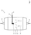
- FIG. 1 The apparatus shown is used to produce a SiO 2 soot body 200.
- a support tube 160 made of aluminum oxide a plurality of arranged in a row Flammhydrolysebrenner 140 is arranged.
- a multiplicity of deposition burners are used, which are reversibly reciprocated for soot deposition in a common burner row along the rotating support, wherein each of the burner flames covers only a partial length of the support tube 160 ,
- the SiO 2 feedstock 105 preferably has more than 95 wt .-%, preferably more than 98 wt .-%, in particular more than 99.5 wt .-% of the polyalkylsiloxane D4 and is supplied to the reaction zone in gaseous form and thereby Oxidation and / or hydrolysis and / or pyrolysis to SiO 2 decomposes.
- the reaction zone is, for example, a burner flame or a plasma.
- SiO 2 particles 148 are formed, which are deposited layer by layer on the deposition surface 160 to form the SiO 2 soot body.
- the SiO 2 particles 148 themselves are in the form of agglomerates or aggregates of SiO 2 primary particles with particle sizes in the nanometer range.
- the flame hydrolysis burners 140 are mounted on a common burner block 141 which is reciprocated parallel to the longitudinal axis 161 of the support tube 160 between two inflection points fixed relative to the longitudinal axis 161 and which is displaceable perpendicular thereto as indicated by the directional arrows 142.
- the burners 140 are made of quartz glass; their center distance from each other is 15 cm.
- the flame hydrolysis burners 140 are each assigned a burner flame 143 which represents a reaction zone in the sense of the invention.
- SiO 2 particles are formed and deposited on the cylinder jacket surface of the carrier tube 160 rotating about its longitudinal axis 161, so that a soot body 200 having an outer diameter of 350 mm is built up in layers.
- a temperature of about 1200 ° C. is established.
- the flame hydrolysis burners 140 are each supplied with oxygen and hydrogen as burner gases and as feed for the formation of the SiO 2 particles the SiO 2 feedstock vapor 107.
- polyalkylsiloxanes encompasses both polyalkylcyclosiloxanes and their linear homologs.
- the production of the SiO 2 feedstock vapor 107 from more than 95% by weight, preferably more than 98% by weight, in particular more than 99.5% by weight, of the polyalkylsiloxane D4 takes place by means of an evaporator system 120, which forms a reservoir 110 for 124, the liquid mixture, a liquid pump 122, a flow meter 123 for liquid, an MFC (m ass f low c ontroller) for the controlled supply of a nitrogen carrier gas stream 152 and a heatable evaporation chamber 125 - includes a spray nozzle 128 - even expansion chamber.
- the reservoir 110, a pump 122 and a spray nozzle 128 are connected to each other by means of flexible metallic lines.
- the reservoir 110 is heated to a temperature of 130-170 ° C, and the heated liquid supplied by the pump 122 via the flow meter 123 in exact dosage of the spray nozzle 128.
- the SiO 2 feedstock 105 is atomized into fine droplets - also referred to as SiO 2 droplets, the SiO 2 droplets having an average diameter of less than 5 ⁇ m, preferably less than 2 ⁇ m.
- a concentration detector for monitoring the composition of the SiO 2 -Einsatzmaterials 105 and / or the SiO 2 -Einsatzdampfes 107 and / or the SiO 2 droplets be provided in the connecting line between the flow meter 123 and atomizer 128th
- the nebulizer 128 - also referred to as nebulizer nozzle - may be an ultrasonic nebulizer.
- This atomizing nozzle 128 ensures that the liquid SiO 2 feedstock is atomized into fine droplets, the droplets having an average diameter of less than 5 ⁇ m, preferably less than 2 ⁇ m.
- the SiO 2 feedstock 105 and / or the droplets can be fed with a nitrogen carrier gas stream via the MFC 123 at a pressure of 1.5 bar to 5 bar.
- the spray nozzle 128 atomizes the SiO 2 feedstock 105 into fine droplets having a maximum diameter of 1 ⁇ m and a narrow droplet size distribution with an average diameter (d 50 value) of 0.7 ⁇ m, and immediately sprays these droplets in an injection phase into the expansion chamber 125 of the evaporator 120 a.
- the evaporator 120 has an internal temperature of 195 ° C, so that the fine liquid droplets evaporate immediately and the vapor stream is fed to a fixed flux divider and is divided by this heat-insulated flexible media supply lines to the individual Abscheidebrenner 140.
- the flow divider also open a supply line for the fuel gases oxygen and hydrogen and an auxiliary gas (oxygen), which is used in the burner flame 143 between the flow of the feedstock and the flow of fuel gas, and counteracts an early mixing.
- oxygen oxygen
- the mixture of fuel gases and the SiO 2 feed steam 107 thus takes place only in the hot zone of the burner flame 143.
- a tube of porous SiO 2 soot Sootrohr
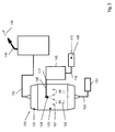
- FIG. 2 and FIG. 3 show the system 100 for producing quartz glass, which uses the inventive method.
- the SiO 2 feedstock material 105 is heated and the atomization takes place by means of a spray nozzle 128, which has an ultrasound system.
- the system 100 has a storage tank 110, from which the liquid SiO 2 feedstock 105 is pumped into a preheating device 115 by means of a pump, not shown.
- the liquid SiO 2 feedstock 105 in the preheater 115 is heated to an elevated temperature.
- the liquid SiO 2 feedstock 105 is pumped into the atomizer nozzle. There is then the atomization of the liquid and the injection of the droplets into the expansion chamber instead.
- the transition of the liquid SiO 2 droplets into the gaseous SiO 2 feedstock steam 107 takes place.
- the SiO 2 feedstock vapor 107 flows to the burner 140, where a pyrolytic or hydrolytic conversion of the SiO 2 feedstock vapor into SiO 2 particles takes place.
- the preheater 115 has an inlet 116 and a drain 117. Through the inlet 116, the SiO 2 feedstock 105 is supplied in the preheater 115. Within the preheater 115 there is a heating of the SiO 2 feedstock 105. This can be done by using a hot oil system or an electric heating element in the walls of the preheater. In order to achieve a uniform heating of the liquid SiO 2 feedstock 105 while avoiding hot areas, it has proved to be advantageous if the preheater 115 has a flow channel which is surrounded by hot oil passages. The thus achievable liquid-to-liquid heat transfer achieves a uniform heating of the liquid SiO 2 feedstock 105. This type of uniform heating ensures that there is no temperature-induced chemical reaction of the polyalkylsiloxanes.
- the heated liquid SiO 2 feedstock 105 is discharged from the preheater 115 into the expansion chamber 125 through a feed line 145.
- the expansion chamber 125 defines an internal volume for the free expansion of the SiO 2 feedstock vapor.
- the temperature of the liquid SiO 2 feedstock is increased above the boiling point of the SiO 2 feedstock at the operating pressure of the expansion chamber .
- a preferred operating temperature for the preheater 115 is about 180 ° C.
- the boiling point of D4 at atmospheric pressure is about 175 ° C.
- backpressure in the preheater is required. In this way, the liquid reactant is maintained as a supercooled (compressed) liquid in the preheater 115.
- the liquid SiO 2 feedstock from the preheater 115 flows through the supply conduit 145 into the interior of the expansion chamber 125.
- the preheater 115 sufficiently heats up the liquid SiO 2 feedstock 105 so that it almost completely vaporizes while it is being pressurized falls into the inner volume of the expansion chamber 125.
- Such an immediate evaporation takes place only if the Preheater 115 has increased the temperature of the liquid SiO 2 feedstock above the boiling point of the SiO 2 feedstock at the operating pressure of the expansion chamber 125.
- the amount of droplets of the SiO 2 feedstock that immediately evaporate thus depends on the amount of heat that is supplied to the liquid SiO 2 feedstock in the preheater 115.
- the system 100 without heating the SiO 2 feedstock 105.
- an atomization of the SiO 2 feedstock takes place only by means of the atomizer nozzle 128, without the SiO 2 feedstock material being heated to an elevated temperature.
- An additional heat input can be effected by a carrier gas, which is also performed, for example, through the atomizer nozzle 128.
- such a variant differs from that in FIG. 3 shown only in that no preheating 115 is needed.
- diluent 152 in particular nitrogen has proved to be advantageous.
- Other diluents such as argon or helium, may also be used if desired. These are gases which are inert with respect to polyalkylsiloxanes, so that oxidation, polymerization or decomposition reactions between the liquid and the carrier gas, in particular under pressure and higher temperature, and thus an irreproducible change in the composition of the feed avoided become.
- the partial pressure of the liquid SiO 2 feedstock - in this case the droplets of the SiO 2 feedstock - in the expansion chamber 125 is reduced and thus its dew point is lowered. This does not require high heating of the SiO 2 feedstock in the preheater 115.
- the evaporation of the SiO 2 feedstock material comprises an injection phase in which the feedstock is atomized into fine droplets in liquid form and an evaporation phase in which the fine droplets are contacted by a hot carrier gas but without contact with Walls of the expansion chamber 125 is completely evaporated quickly and efficiently.
- the FIG. 3 illustrates the evaporation of the invention.
- the heated SiO 2 feedstock 105 is supplied through the supply line 145 to the expansion chamber 125.
- the supply line 145 has a nozzle-like spray nozzle 128.
- the atomizer nozzle 128 - which is preferably an ultrasonic atomizer - the liquid SiO 2 feedstock 105 is atomized into fine droplets, which have a mean diameter of less than 5 .mu.m, preferably less than 2 .mu.m, in particular less than one micron.
- Particularly preferred measurement series were between 0.5 ⁇ m and 20 nm (d 50 value).
- the median value or d 50 value is the most important parameter as a measure of the average particle size.
- the d 50 value describes the value at which 50 percent of the droplets are finer and the others 50 percent coarser than d 50 .
- the nitrogen stream has a temperature which corresponds essentially - ie to +/- 10 ° C - the temperature of the liquid SiO 2 feedstock 105.
- the nitrogen stream may flow counter to the spray direction of the liquid SiO 2 feedstock 105 so as to ensure high mixing and heat transfer.
Description
Die Erfindung betrifft ein Verfahren zur Herstellung von synthetischem Quarzglas, umfassend die Verfahrensschritte:
- (A) Bereitstellen eines flüssigen SiO2-Einsatzmaterials, welches mehr als 70 Gew.-% des Polyalkylsiloxans D4 aufweist,
- (B) Verdampfen des flüssigen SiO2-Einsatzmaterials (105) in einen gasförmigen SiO2-Einsatzdampf (107),
- (C) Umsetzen des SiO2-Einsatzdampfes (107) zu SiO2-Partikeln,
- (D) Abscheiden der SiO2-Partikel auf einer Ablagerungsfläche (160) unter Bildung eines SiO2-Sootkörpers (200),
- (E) Verglasen des SiO2-Sootkörpers unter Bildung des synthetischen Quarzglases.
- (A) providing a liquid SiO 2 feedstock comprising more than 70% by weight of the polyalkylsiloxane D4,
- (B) vaporizing the liquid SiO 2 feedstock (105) into a gaseous SiO 2 feedstock vapor (107),
- (C) reacting the SiO 2 feedstock vapor (107) to SiO 2 particles,
- (D) depositing the SiO 2 particles on a deposition surface (160) to form an SiO 2 soot body (200),
- (E) vitrifying the SiO 2 soot body to form the synthetic quartz glass.
Zur Herstellung von synthetischem Quarzglas für kommerzielle Anwendungen werden chlorfreie Einsatzmaterialien erprobt. Als Beispiel seien Monosilane, Alkoxysilane und Siloxane genannt. Eine besonders interessante Gruppe chlorfreier Einsatzmaterialien bilden die Polyalkylsiloxane (auch kurz als "Siloxane" bezeichnet), die beispielsweise aus der
Polyalkylsiloxane zeichnen sich durch einen besonders hohen Anteil an Silizium pro Gewichtsanteil aus, was zur Wirtschaftlichkeit ihres Einsatzes bei der Herstellung von synthetischem Quarzglas beiträgt. Wegen der großtechnischen Verfügbarkeit in hoher Reinheit wird derzeit Octamethylcyclotetrasiloxan (OMCTS) bevorzugt eingesetzt. Diese Substanz wird gemäß einer von General Electric Inc. eingeführten Notation auch als "D4" bezeichnet, wobei "D" die Gruppe [(CH3)2Si]-0- repräsentiert.Polyalkylsiloxanes are distinguished by a particularly high proportion of silicon per part by weight, which contributes to the cost-effectiveness of their use in the production of synthetic quartz glass. Because of the large-scale availability in high purity, octamethylcyclotetrasiloxane (OMCTS) is currently preferred used. This substance is also referred to as "D4" according to a notation introduced by General Electric Inc., where "D" represents the group [(CH 3 ) 2 Si] -O-.
Aus
In der
Das siliziumhaltige Einsatzmaterial kann dem Verbraucher, wie etwa einem Abscheidebrenner, in flüssiger Form zugeführt werden. In der Regel wird das flüssige Einsatzmaterial aber mittels eines Verdampfers in eine gasförmige oder dampfförmige Phase überführt und dem Verbraucher ein kontinuierlicher Gasstrom zugeführt. Bei den bekannten Verdampfungssystemen wird die zu verdampfende Flüssigkeit mit einer heißen Oberfläche in Kontakt gebracht. Heiße Oberflächen können insbesondere bei organischem Einsatzmaterial zu unvorhergesehenen Veränderungen führen, wie beispielsweise Zersetzungen oder Polymerisationen, so dass nicht ohne Weiteres nachvollziehbar ist, inwieweit die Zusammensetzung des Dampfes noch der der Flüssigkeit entspricht. Daraus ergibt sich eine gewisse Variabilität und Unreproduzierbarkeit in der Prozessführung, die zu Fehlern im Partikelbildungsprozess und zu Inhomogenitäten im Sootaufbau führen kann.The siliceous feed may be supplied to the consumer, such as a deposition burner, in liquid form. In general, however, the liquid feedstock is converted by means of an evaporator into a gaseous or vaporous phase and supplied to the consumer a continuous gas flow. In the known evaporation systems, the liquid to be evaporated is brought into contact with a hot surface. Hot surfaces can lead to unforeseen changes, in particular in the case of organic feedstock, such as, for example, decompositions or polymerizations, so that it is not easy to understand to what extent the composition of the steam still corresponds to that of the liquid. This results in a certain variability and unreproducibility in the process, which can lead to errors in the particle formation process and inhomogeneities in the soot buildup.
Es ist die Aufgabe der vorliegenden Erfindung, ein Verfahren zur Herstellung von SiO2-Sootkörpern mit hoher Materialhomogenität zu schaffen, bei dem die genannten Nachteile vermieden werden.It is the object of the present invention to provide a method for the production of SiO 2 soot bodies with high material homogeneity, in which the mentioned disadvantages are avoided.
Diese Aufgabe wird ausgehend von dem eingangs genannten Verfahren erfindungsgemäß dadurch gelöst, dass das Verdampfen des erhitzten SiO2-Einsatzmaterials eine Injektionsphase in einer Expansionskammer umfasst, in der das SiO2-Einsatzmaterial in feine Tröpfchen zerstäubt wird, wobei die Tröpfchen einen mittleren Durchmesser von weniger als 5 µm, vorzugsweise weniger als 2 µm, aufweisen.This object is achieved on the basis of the above-mentioned method according to the invention in that the evaporation of the heated SiO 2 feedstock material comprises an injection phase in an expansion chamber in which the SiO 2 feedstock is atomized into fine droplets, the droplets having an average diameter of less than 5 μm, preferably less than 2 μm.
Im Unterschied zu den bekannten Verfahren, bei denen ein Einsatzmaterial eingesetzt wird, das aus einer einzigen, möglichst reinen und definierten Siliziumverbindung (z.B. SiCl4) besteht, wird erfindungsgemäß ein SiO2-Einsatzmaterial vorgeschlagen, welches Octamethylcyclotetrasiloxan (hier auch als D4 bezeichnet) als Hauptkomponente enthält.In contrast to the known methods in which a feedstock is used, which consists of a single, pure and defined as possible silicon compound (For example, SiCl 4 ), the present invention proposes a SiO 2 feedstock containing octamethylcyclotetrasiloxane (also referred to herein as D4) as a main component.
Die Besonderheit des erfindungsgemäßen Verfahrens besteht darin, dass die Verdampfung des SiO2-Einsatzmaterials sich durch einen besonders gleichmäßigen Wärmeeintrag auszeichnet. Im Stand der Technik ist es bekannt, Flüssigkeiten über heiße Flächen strömen zu lassen, um so einen Wärmeeintrag und eine Verdampfung zu erzielen. Allerdings führt ein solches Vorgehen bei einem SiO2-Einsatzmaterial, welches auf dem Polyalkylsiloxan D4 basiert, zu einer Gelbildung, die den Verdampfer und/oder die heißen Flächen verstopfen kann. Um jenen Nachteil zu überwinden, ist es erfindungsgemäß vorgesehen, dass das SiO2-Einsatzmaterial in einer Expansionskammer verdampft wird. Dabei strömt das SiO2-Einsatzmaterial durch eine Zuführungsleitung in die Expansionskammer ein. Entgegen bekannten Verfahren, zeichnet sich das erfindungsgemäße Verfahren dadurch aus, dass eine Zerstäuberdüse genutzt wird. Diese ermöglicht es, das flüssige SiO2-Einsatzmaterial in mikrometergroße Flüssigkeitskugeln zu zerstäuben. Solcherart Flüssigkeitskugeln - auch als Tropfen bezeichnet - weisen eine große Oberfläche im Verhältnis zu dem Volumen auf. Durch die Kugelform ist weiterhin sichergestellt, dass ein gleichmäßiger Wärmeeintrag in die Flüssigkeit stattfindet. Somit wird der Flüssigkeitstropfen mit den D4-Molekülen gleichmäßig erwärmt und eine thermische Aufspaltung der Polyalkylsiloxane verhindert. Dadurch wird die Menge der im Verdampfungsprozess entstehenden Gele deutlich reduziert, was in einer homogeneren Dichteverteilung des Sootkörpers - und damit des Quarzglases - resultiert.The peculiarity of the method according to the invention is that the evaporation of the SiO 2 feedstock is characterized by a particularly uniform heat input. In the prior art, it is known to flow liquids over hot surfaces, so as to achieve a heat input and evaporation. However, such a procedure for a SiO 2 feedstock based on the polyalkylsiloxane D4 results in gelation that can clog the evaporator and / or the hot surfaces. To overcome this disadvantage, it is provided according to the invention that the SiO 2 feedstock is evaporated in an expansion chamber. In this case, the SiO 2 feedstock flows through a supply line into the expansion chamber. Contrary to known methods, the method according to the invention is characterized in that an atomizer nozzle is used. This makes it possible to atomize the liquid SiO 2 feedstock into micron-sized liquid spheres. Such liquid balls - also referred to as drops - have a large surface area in relation to the volume. The spherical shape also ensures that a uniform heat input into the liquid takes place. Thus, the liquid drop is uniformly heated with the D4 molecules and prevents thermal decomposition of the polyalkylsiloxanes. As a result, the amount of gels formed in the evaporation process is significantly reduced, resulting in a more homogeneous density distribution of the soot body - and thus of the quartz glass.
Um die erfindungsgemäßen Vorteile zu erlangen, ist es notwendig, dass der Zerstäuberkopf dafür sorgt, dass das flüssige SiO2-Einsatzmaterial in feine Tröpfchen zerstäubt wird, deren mittlerer Durchmesser weniger als 5 Mikrometer (im Weiteren auch "µm") beträgt. Im Rahmen einer Mehrzahl von Messungen konnte ermittelt werden, dass die Gelbildung bzw. die Inhomogenitäten im Sootmaterial besonders stark reduziert wurden, wenn die Tröpfchen einen mittleren Durchmesser zwischen 0,5 µm und 2 µm aufweisen. Besonders bevorzugt Messreihen ergaben sich zwischen 0,5 µm und 20 nm (d50-Wert). Der Medianwert oder d50-Wert ist dabei als Maß für die mittlere Teilchengröße die wichtigste Kenngröße. Der d50-Wert beschreibt jenen Wert, bei dem 50 Prozent der Tröpfchen feiner sind und die anderen 50% grober sind als d50. Darüberhinaus sollte die Schwankungsbreite der mittleren Tröpfchengröße möglichst gering sein. Besonders bevorzugte Ergebnisse konnten erzielt werden, wenn die Tröpfchengrößen in der 2σ Varianz nur um + 1 µm und - 0,35 µm schwankten. Diese geringe Schwankungsbreite führte dazu, dass ein sehr gleichmäßiger Nebel feiner Tröpfchen in den Innenraum der Expansionskammer eingesprüht wurde. Jene gleichmäßigen Flüssigkeitstropfen aus SiO2-Einsatzmaterial können dann durch Wärmeeinstrahlung der inneren Wände der Expansionskammer und/oder Wärmeübertrag aus einem erhitzten Trägergas in die Gasphase überführt werden. Ziel des erfindungsgemäßen Verfahrens ist es dabei auch, zu verhindern, dass die Tröpfchen des SiO2-Einsatzmaterials auf Innenwände der Expansionskammer auftreffen und erst an diesen verdampfen. Vielmehr soll die Verdampfung ausschließlich im freien Raum der Expansionskammer stattfinden. Zwar mag die Innenwand der Expansionskammer erwärmt sein und die Wärmestrahlung zu einer Verdampfung der Flüssigkeitstropfen des SiO2-Einsatzmaterials beitragen, aber es muss verhindert werden, dass ein direkter Kontakt zwischen den erhitzten - metallischen - Innenwänden und dem SiO2-Einsatzmaterial auftritt. Denn, wie dargelegt, führt ein Kontakt des SiO2-Einsatzmaterials mit den erhitzten Innenwänden der Expansionskammer zu einer Gelbildung, die erfindungsgemäß verhindert werden soll.In order to obtain the advantages of the invention, it is necessary that the atomizing head ensures that the liquid SiO 2 feedstock is atomized into fine droplets whose mean diameter is less than 5 micrometers (hereinafter also "μm"). Within the scope of a large number of measurements, it could be determined that the gel formation or the inhomogeneities in the soot material were particularly greatly reduced if the droplets have an average diameter of between 0.5 μm and 2 μm. Particularly preferred measurement series were between 0.5 μm and 20 nm (d 50 value). The median value or d 50 value is included as a measure of the mean particle size the most important parameter. The d 50 value describes the value at which 50 percent of the droplets are finer and the others 50 percent coarser than d 50 . Moreover, the fluctuation range of the average droplet size should be as small as possible. Particularly preferred results could be achieved if the droplet sizes in the 2σ variance varied only by + 1 μm and -0.35 μm. This small range of variation caused a very uniform mist of fine droplets to be sprayed into the interior of the expansion chamber. Those uniform liquid droplets of SiO 2 feedstock can then be converted into the gas phase by heat radiation of the inner walls of the expansion chamber and / or heat transfer from a heated carrier gas. It is also an object of the method according to the invention to prevent the droplets of the SiO 2 feedstock from impinging on inner walls of the expansion chamber and only evaporating therefrom. Rather, the evaporation should take place exclusively in the free space of the expansion chamber. While the inner wall of the expansion chamber may be heated and the thermal radiation may contribute to vaporization of the liquid droplets of the SiO 2 feedstock, it is necessary to prevent direct contact between the heated metallic innerwalls and the SiO 2 feedstock. Because, as stated, a contact of the SiO 2 feedstock with the heated inner walls of the expansion chamber to a gel formation, which is to be prevented according to the invention.
Im Rahmen der Erfindung umfasst der Begriff Polyalkylsiloxan sowohl lineare als auch zyklische Molekularstrukturen. Allerdings ist es bevorzugt, wenn das SiO2-Einsatzmaterial als Hauptbestandteil D4 aufweist. Die Notation D3, D4, D5 entstammt einer von General Electric Inc. eingeführten Notation, bei der "D" die Gruppe [(CH3)2Si]-0- repräsentiert. Somit beschreibt D3 Hexamethylcyclotrisiloxan, D4 Octamethylcyclotetrasiloxan, D5 Decamethylcyclopentasiloxan und D6 Dodecamethylcyclohexasiloxan. In einer bevorzugten Variante ist die Hauptkomponente des SiO2-Einsatzmaterials D4. So ist der Anteil an D4 mindestens 70 Gew.-%, insbesondere mindestens 80 Gew.-%, bevorzugt mindestens 90 Gew.-%, besonders bevorzugt mindestens 94 Gew.-% an dem SiO2-Einsatzmaterial.In the context of the invention, the term polyalkylsiloxane encompasses both linear and cyclic molecular structures. However, it is preferable that the SiO 2 feedstock has D4 as the main constituent. The notation D3, D4, D5 is taken from a notation introduced by General Electric Inc. in which "D" represents the group [(CH 3 ) 2 Si] -0-. Thus D3 describes hexamethylcyclotrisiloxane, D4 octamethylcyclotetrasiloxane, D5 decamethylcyclopentasiloxane and D6 dodecamethylcyclohexasiloxane. In a preferred variant, the main component of the SiO 2 feedstock is D4. Thus, the proportion of D4 is at least 70% by weight, in particular at least 80% by weight, preferably at least 90% by weight, particularly preferably at least 94% by weight, of the SiO 2 feedstock.
Im Rahmen der Erfindung beschreibt der Begriff "Taupunkt" die Temperatur, bei der sich ein Gleichgewichtszustand von kondensierender und verdunstender Flüssigkeit einstellt.In the context of the invention, the term "dew point" describes the temperature at which an equilibrium state of condensing and evaporating liquid sets.
Im Rahmen der Erfindung werden die Begriffe "Verdünnungsmittel" und,, "Trägergas" gleichbedeutend verwendet.In the context of the invention, the terms "diluent" and "carrier gas" are used synonymously.
Im Rahmen der Erfindung findet ein flüssiges SiO2-Einsatzmaterial Verwendung, welches aus mehr als 70 Gew.-% des Polyalkylsiloxanes Octamethylcyclotetrasiloxan D4 und dessen linearem Homolog aufgebaut ist. Zusätzlich kann das flüssige SiO2-Einsatzmaterial noch Zusatzkomponenten anderer Polyalkylcyclosiloxane wie D3, D5, D6, D7 und D8 aufweisen. Die unter dem Begriff "Zusatzkomponenten" zusammengefassten zusätzlichen Bestandteile des Einsatzmaterials haben somit Molekülmassen und Siedetemperaturen, die sich nach oben und/oder nach unten von der relativen Molekülmasse von D4 (etwa 297 g/mol) und in der Siedetemperatur von D4 (etwa 175° C) unterscheiden. Das möglicherweise Zusatzkomponenten aufweisende, flüssige SiO2-Einsatzmaterial wird einer Reaktionszone in gasförmiger Form zugeführt und dabei durch Oxidation und/oder Hydrolyse und/oder Pyrolyse zu SiO2 zersetzt.In the context of the invention, a liquid SiO 2 feedstock is used which is composed of more than 70% by weight of the polyalkylsiloxane octamethylcyclotetrasiloxane D4 and its linear homologue. In addition, the liquid SiO 2 feedstock may still contain additional components of other polyalkylcyclosiloxanes such as D3, D5, D6, D7 and D8. The additional constituents of the feedstock combined under the term "additional components" thus have molecular weights and boiling temperatures which are upwards and / or downwards from the molecular weight of D4 (about 297 g / mol) and at the boiling point of D4 (about 175.degree C) differ. The liquid SiO 2 feedstock possibly having additional components is fed to a reaction zone in gaseous form and decomposed by oxidation and / or hydrolysis and / or pyrolysis to form SiO 2 .
Mit dem hier offenbarten erfindungsgemäßen Verfahren ist es möglich, auch sehr große Mengen SiO2-Einsatzmaterial gleichmäßig und schnell zu verdampfen. Somit kann die Anzahl der Verdampfer reduziert werden, die benötigt wird, um großvolumige, zylinderförmige Sootkörper mit einem Außendurchmesser von mehr als 300 mm aufzubauen. Erfindungsgemäß weisen die Verdampfer Verdampfungsraten von 15 bis 25 kg pro Stunde vom Polyalkylsiloxan D4 auf. Nur mittels des erfindungsgemäßen Verfahrens ist es möglich, eine so große Menge SiO2-Einsatzmaterial in die Gasphase zu überführen. Eine Nutzung bekannter Verdampfungstechnologien würde voraussetzen, dass große, stark erhitzte Metallflächen zur Verdampfung genutzt würden. Im Rahmen des Kontakts des SiO2-Einsatzmaterials mit den stark erhitzten Metallflächen würden sich aber Polymerisation und/oder thermische Aufspaltung des D4 ergeben. Diese Nachteile könnten dann zu einer Verstopfung und/oder Verschlechterung der Leistungsfähigkeit des Verdampfers, sowie zu Inhomogenitäten in dem Sootkörper bzw. dem Quarzglas führen. Nur die Zerstäubung des SiO2-Einsatzmaterials in seiner flüssigen Form in kleine Flüssigkeitstropfen mit einem geringen Durchmesser ermöglicht es, große Mengen des SiO2-Einsatzmaterials gleichmäßig zu erhitzen, ohne dass dabei Gele oder sonstige Abfallstoffe entstehen können, die sich nachteilig auf die Wirkung des Verdampfers und/oder die Homogenität des Sootkörpers auswirken können.With the method according to the invention disclosed here, it is possible to evaporate even very large amounts of SiO 2 feedstock evenly and rapidly. Thus, the number of evaporators needed to build large volume cylindrical soot bodies having an outside diameter of more than 300 mm can be reduced. According to the invention, the evaporators have evaporation rates of 15 to 25 kg per hour of the polyalkylsiloxane D4. Only by means of the method according to the invention is it possible to convert such a large amount of SiO 2 feedstock into the gas phase. Using known evaporation technologies would require large, heavily heated metal surfaces to be used for evaporation. However, as part of the contact of the SiO 2 feedstock with the highly heated metal surfaces, polymerization and / or thermal decomposition of the D4 would result. These disadvantages could then lead to a clogging and / or deterioration of the efficiency of the evaporator, as well as to inhomogeneities in the soot body or the quartz glass to lead. Only the sputtering of the SiO 2 feedstock in its liquid form into small liquid droplets with a small diameter makes it possible to uniformly heat large quantities of the SiO 2 feedstock without causing gels or other wastes that adversely affect the effect of the Evaporator and / or the homogeneity of the soot body can affect.
Um eine gleichmäßige Umsetzung der flüssigen Tröpfchen des SiO2-Einsatzmaterials in den SiO2-Einsatzdampf zu erzielen, wird vorteilhafterweise ein Trägergas genutzt, welches durch die Expansionskammer des Verdampfers hindurch strömt. Vorteilhafterweise wird dabei eine Menge zwischen 8 und 20 m3/h eines Inertgases wie Stickstoff oder Argon genutzt. Dieses Trägergas sollte einen maximalen Vordruck zwischen 2 und 8 bar besitzen, um so zum einen schnell genug durch die Expansionskammer hindurchzuströmen, andererseits aber nicht zu einer Beeinträchtigung der Zerstäuberdüse zu führen. Vorteilhafterweise ist das Trägergas vorgewärmt und weist eine Temperatur im Bereich zwischen 130° C bis 180° C auf. Damit ist es möglich, ein Gemisch aus SiO2-Einsatzdampf und Trägergas zu erzeugen, welches ebenfalls zwischen 130° C und 180° C aufweist und mit einem Druck zwischen 1,1 und 2 bar aus der Expansionskammer in Richtung des Verdampfers geführt wird. Die Temperatur innerhalb des Verdampfers sollte 200° C nicht überschreiten, da das D4 sonst polymerisieren könnte.In order to achieve a uniform conversion of the liquid droplets of the SiO 2 feedstock into the SiO 2 feedstock vapor, it is advantageous to use a carrier gas which flows through the expansion chamber of the evaporator. Advantageously, an amount of between 8 and 20 m 3 / h of an inert gas such as nitrogen or argon is used. This carrier gas should have a maximum pre-pressure between 2 and 8 bar, so as to flow through the expansion chamber fast enough, but on the other hand not to lead to an impairment of the atomizer. Advantageously, the carrier gas is preheated and has a temperature in the range between 130 ° C to 180 ° C. It is thus possible to produce a mixture of SiO 2 feedstock vapor and carrier gas, which likewise has a temperature of between 130 ° C. and 180 ° C. and is conducted at a pressure of between 1.1 and 2 bar out of the expansion chamber in the direction of the evaporator. The temperature inside the evaporator should not exceed 200 ° C, otherwise the D4 could polymerize.
Eine Verringerung der Breite des Spektrums der Tröpfchengröße kann dadurch erzeugt werden, dass auf einen Flüssigkeitsstrahl eine gleichförmige, zyklische Störung aufprägt wird. Dies kann dadurch erreicht werden, dass man an der Zerstäuberdüse eine mechanische Schwingung oder eine Ultraschallquelle anlegt. Die Störung verursacht eine regelmäßige Ausbreitungswelle längs des Strahls, die schließlich den Strahl in nahezu gleichförmige Tröpfchen aufbricht. Erfindungsgemäß soll die Ausgestaltung des Zerstäuberkopfs derart sein, dass nur ein schmales Spektrum von Tröpfchengrößen erzeugt wird.A reduction in the width of the spectrum of droplet size can be produced by imparting uniform, cyclic interference to a liquid jet. This can be achieved by applying a mechanical vibration or an ultrasonic source to the atomizer nozzle. The perturbation causes a regular propagation wave along the beam, which eventually breaks up the beam into nearly uniform droplets. According to the invention, the design of the atomizer head should be such that only a narrow spectrum of droplet sizes is generated.
Herstellungsbedingt haben Sootkörper eine gewisse Schichtstruktur, wobei die Schichten Bereiche lokaler Änderungen der Dichte oder der chemischen Zusammensetzung darstellen. Es hat sich gezeigt, dass bei erfindungsgemäßem Einsatz eines Verdampfungsprozesses ein SiO2-Sootkörper mit überraschend hoher Homogenität, insbesondere mit gleichmäßiger und schwacher Ausprägung der Schichtstruktur erhalten wird. Dies erklärt sich durch die Nutzung des erfindungsgemäßen Verfahrens, welches die Erzeugung von kleinen Tröpfchen bei einem schmalen Spektrum von Tröpfchengrößen beinhaltet.As a result of production, soot bodies have a certain layer structure, the layers representing areas of local changes in density or chemical composition. It has been found that when using an evaporation process according to the invention, an SiO 2 soot body having surprisingly high homogeneity, is obtained in particular with uniform and weak expression of the layer structure. This is explained by the use of the method according to the invention, which involves the generation of small droplets with a narrow spectrum of droplet sizes.
Eine weitere vorteilhafte Ausgestaltung des erfindungsgemäßen Verfahrens zeichnet sich dadurch aus, dass die Zusatzkomponente D3 und/oder die Zusatzkomponente D5 maximal zwischen 0,1 Gew.-% und 2 Gew.-% eines Gesamtgewichtes des flüssigen SiO2-Einsatzmaterials stellen, insbesondere die Summe der Gewichtsanteile mD3 + mD5 maximal im Bereich zwischen 0,5 und 3 Gew.-%, bevorzugt maximal zwischen 0,2 und 2 Gew.-% liegt. Da Dodekamethylcyclohexasiloxan (D6) und deren lineare Homologen wegen ihrer großen Molekülmasse im Vergleich zu D4 bereits in geringer Konzentration eine merkliche Veränderung der Reaktionszone und des Partikelbildungsprozesses bewirken, beträgt der Gewichtsanteil von D6 vorzugsweise nicht mehr als 100 Gew.-ppm. Durch die geringen Mengen der Zusatzkomponente D3 und/oder D5 lässt sich die Temperatur und das Spektrum der Tröpfchengrößen besser optimieren. Dies resultiert in einem besonders homogenen SiO2-Sootkörper.A further advantageous embodiment of the method according to the invention is characterized in that the additional component D3 and / or the additional component D5 represent a maximum of between 0.1 wt .-% and 2 wt .-% of a total weight of the liquid SiO 2 feedstock, in particular the sum the proportion by weight of mD3 + mD5 is at most in the range between 0.5 and 3 wt .-%, preferably at most between 0.2 and 2 wt .-%. Since dodecamethylcyclohexasiloxane (D6) and its linear homologs already cause a noticeable change in the reaction zone and the particle formation process in small concentrations compared to D4, the weight fraction of D6 is preferably not more than 100 ppm by weight. Due to the small amounts of the additional component D3 and / or D5, the temperature and the spectrum of the droplet sizes can be better optimized. This results in a particularly homogeneous SiO 2 soot body.
Bei den bekannten Verdampfungssystemen wird die zu verdampfende Flüssigkeit mit einer heißen Oberfläche in Kontakt gebracht. Heiße Oberflächen können insbesondere bei organischem Einsatzmaterial zu unvorhergesehenen Veränderungen führen, wie beispielsweise Zersetzungen oder Polymerisationen, so dass nicht ohne Weiteres nachvollziehbar ist, inwieweit die Zusammensetzung des Dampfes noch der der Flüssigkeit entspricht. Daraus ergibt sich eine gewisse Variabilität und Unreproduzierbarkeit in der Prozessführung, die zu Fehlern im Partikelbildungsprozess und zu Inhomogenitäten im Sootaufbau führen kann.In the known evaporation systems, the liquid to be evaporated is brought into contact with a hot surface. Hot surfaces can lead to unforeseen changes, in particular in the case of organic feedstock, such as, for example, decompositions or polymerizations, so that it is not easy to understand to what extent the composition of the steam still corresponds to that of the liquid. This results in a certain variability and unreproducibility in the process, which can lead to errors in the particle formation process and inhomogeneities in the soot buildup.
Um diese Nachteile zu überwinden, ergibt sich eine weitere vorteilhafte Ausgestaltung des erfindungsgemäßen Verdampfungsprozesses dadurch, dass das Verdampfen die folgenden Schritte umfasst:
- Erhitzen des SiO2-Einsatzmaterials,
- Einführen des erhitzten SiO2-Einsatzmaterials in eine Expansionskammer, so dass zumindest ein erster Teil des SiO2-Einsatzmaterials und/oder die Tröpfchen des SiO2-Einsatzmaterials in Folge eines Druckabfalls verdampfen.
- Heating the SiO 2 feedstock,
- Introducing the heated SiO 2 feedstock into an expansion chamber so that at least a first portion of the SiO 2 feedstock and / or the droplets of the SiO 2 feedstock evaporate as a result of a pressure drop.
Im Rahmen dieser Ausgestaltung findet eine Erhitzung des SiO2-Einsatzmaterials statt. Dabei werden Temperaturen des SiO2-Einsatzmaterials zwischen 150° C und 200° C angestrebt. Höhere Temperaturen könnten gegebenenfalls zu einer Polymerisation führen. Als vorteilhaft hat sich die Verwendung eines Flüssig/Flüssig-Heizsystems erwiesen, bei dem das SiO2-Einsatzmaterial mittels einer weiteren Flüssigkeit, wie etwa Öl, erhitzt wird. Durch einen Flüssig/Flüssig-Wärmetauscher findet eine gleichmäßige, konstante Erwärmung des SiO2-Einsatzmaterials statt, ohne dass dabei singuläre, heiße Bereiche auftreten, wie dies etwa bei elektrischen Heizdrähten der Fall ist. Solcherart singulärer Heizpunkte führen schnell zu Polymerisationsreaktionen, die verhindert werden sollen. Nach dem Erhitzen des SiO2-Einsatzmaterials findet ein Zerstäuben dieses erhitzten Materials in die Expansionskammer statt. Innerhalb der Expansionskammer werden das SiO2-Einsatzmaterial und/oder die Tröpfchen des SiO2-Einsatzmaterials in die Gasphase umgesetzt. Als besonders schonend für das SiO2-Einsatzmaterial hat es sich herausgestellt, wenn diese Verdampfung in Folge eines Druckabfalls geschieht. Dazu kann beispielsweise das SiO2-Einsatzmaterial als eine überkritische Flüssigkeit erhitzt werden. Nur durch einen entsprechenden Druck innerhalb der Aufheizvorrichtung wird ein Sieden des SiO2-Einsatzmaterials verhindert. Bei der Expansion innerhalb der Expansionskammer entspannen sich das SiO2-Einsatzmaterial und/oder die Tröpfchen des SiO2-Einsatzmaterials derart, dass sie in die Gasphase übergehen. Als vorteilhaft haben sich Druckabfälle zwischen 1,8 und 5 bar herausgestellt.In the context of this embodiment, heating of the SiO 2 feedstock takes place. In this case, temperatures of the SiO 2 feedstock between 150 ° C and 200 ° C are desired. Higher temperatures could possibly lead to a polymerization. It has proved advantageous to use a liquid / liquid heating system in which the SiO 2 feedstock is heated by means of another liquid, such as oil. By means of a liquid / liquid heat exchanger, a uniform, constant heating of the SiO 2 feedstock takes place without singular hot areas occurring, as is the case, for example, with electrical heating wires. Such singular heating points quickly lead to polymerization reactions that are to be prevented. After heating the SiO 2 feedstock, sputtering of this heated material into the expansion chamber takes place. Within the expansion chamber, the SiO 2 feedstock and / or the droplets of the SiO 2 feedstock are converted to the gas phase. It has been found to be particularly gentle on the SiO 2 feedstock material when this evaporation occurs as a result of a pressure drop. For example, the SiO 2 feedstock may be heated as a supercritical fluid. Only a corresponding pressure within the heating device prevents boiling of the SiO 2 feedstock. Upon expansion within the expansion chamber, the SiO 2 feedstock and / or the droplets of the SiO 2 feedstock relax so that they transition to the gas phase. Advantageously, pressure drops between 1.8 and 5 bar have been found.
Das erhitzte, unter Druck stehende Einsatzmaterial wird durch einen Zuführungskanal in die Expansionskammer eingeführt und dann über einen entsprechenden Sprühkopf vernebelt und/oder zerstäubt. Direkt über der Zerstäuberdüse kann der genannte Druckabfall stattfinden und so für eine schnelle, aber gleichmäßige Überführung des SiO2-Einsatzmaterials in den SiO2-Einsatzdampf Sorge tragen. Im Rahmen dieser Verfahrensschritte ist vorgesehen, dass das SiO2-Einsatzmaterial unter Druck in die Zerstäuberdüse eingeführt wird. In der Zerstäuberdüse findet dann das Zerstäuben des flüssigen SiO2-Einsatzmaterials in die SiO2-Tröpfchen statt. Anschließend treten dann diese Tröpfchen - welche ebenfalls noch unter Druck stehen - in die Expansionskammer ein. Dort entsteht der eigentliche Druckabfall, der für das eigentliche Verdampfen der Tröpfchen sorgt. Vorteilhafterweise ist auch die Expansionskammer selber auf eine Temperatur im Bereich zwischen 150° C und 200° C erhitzt. Zwar soll die Expansionskammer nicht für die Verdampfung sorgen, aber die zur Verfügung gestellte Wärme, welche von den Wänden der Expansionskammer auch in das Innere der Expansionskammer strahlt, unterstützt die Verdampfung in Folge des Druckabfalls.The heated, pressurized feed is introduced into the expansion chamber through a feed channel and then atomized and / or atomized via a respective spray head. Directly above the atomizer nozzle, said pressure drop can take place and thus ensure rapid but uniform transfer of the SiO 2 feedstock into the SiO 2 feedstock vapor. As part of these process steps, it is provided that the SiO 2 feedstock is introduced under pressure into the atomizer nozzle. In the atomizer nozzle For example, the sputtering of the liquid SiO 2 feedstock into the SiO 2 droplets then takes place. Then these droplets - which are also under pressure - enter the expansion chamber. There, the actual pressure drop is created, which ensures the actual evaporation of the droplets. Advantageously, the expansion chamber itself is heated to a temperature in the range between 150 ° C and 200 ° C. Although the expansion chamber should not provide for evaporation, but the heat provided, which radiates from the walls of the expansion chamber into the interior of the expansion chamber, supports the evaporation due to the pressure drop.
Das Größenspektrum der Tröpfchen hängt von einer Vielzahl an Einflussgrößen ab. Neben den rheologischen Eigenschaften der Flüssigkeit und der Geometrie der Zerstäubungsdüse ist dies insbesondere die Austrittsgeschwindigkeit der Flüssigkeit aus der Zerstäubungsdüse, die im Wesentlichen von der Druckdifferenz bestimmt wird. Innerhalb des genannten Druckdifferenzbereichs zerfällt der austretende Flüssigkeitsstrahl aufgrund turbulenter Strömung zu feinen Tropfen mit enger Tropfengrößenverteilung.The size spectrum of the droplets depends on a variety of factors. In addition to the rheological properties of the liquid and the geometry of the atomizing nozzle, this is in particular the exit velocity of the liquid from the atomizing nozzle, which is essentially determined by the pressure difference. Within the mentioned pressure difference range, the exiting liquid jet decays due to turbulent flow to fine droplets with narrow droplet size distribution.
Eine weitere vorteilhafte Ausgestaltung des erfindungsgemäßen Verdampfungsprozesses ergibt sich dadurch, dass das Verdampfen die Schritte umfasst:
- Erhitzen des Si02- Einsatzmaterials,
- Einführen des erhitzten Si02- Einsatzmaterials in die Expansionskammer,
- Vermischen des Si02-Einsatzmaterials und/oder der Tröpfchen des Si02-Einsatzmaterials mit einem erhitzten Verdünnungsmittel, so dass zumindest ein zweiter Teil Si02-Einsatzmaterials in Folge einer Senkung des Taupunktes verdampft.
- Heating the SiO 2 feedstock,
- Introducing the heated SiO 2 feedstock into the expansion chamber,
- Mixing the SiO 2 feedstock and / or the droplets of the SiO 2 feedstock with a heated diluent so that at least a second portion of SiO 2 feedstock evaporates as a result of lowering the dew point.
Im Rahmen dieser Ausführungsvariante wird zur Verdampfung des SiO2-Einsatzmaterials und/oder der Tröpfchen des SiO2-Einsatzmaterials ein Verdünnungsmittel genutzt. Vorteilhafterweise handelt es sich bei dem Verdünnungsmittel um ein inertes Trägergas, welches die Expansionskammer durchströmt. Aus diesem Grund wird im Folgenden der Begriff Verdünnungsgas und der Begriff Trägergas als gleichbedeutend angesehen.In the context of this embodiment, a diluent is used to evaporate the SiO 2 feedstock and / or the droplets of the SiO 2 feedstock. Advantageously, the diluent is an inert carrier gas which flows through the expansion chamber. For this Reason, the term dilution gas and the term carrier gas is considered to be synonymous in the following.
Im Rahmen dieser Ausführungsvariante findet ebenfalls ein Erhitzen des SiO2-Einsatzmaterials statt. Wie schon dargelegt, hat es sich als vorteilhaft erwiesen, wenn die Erhitzung mittels eines Wärmetauschers geschieht und zu einer Erhitzung des SiO2-Einsatzmaterials auf eine Temperatur im Bereich von 120 bis 200°C führt. Das SiO2-Einsatzmaterial wird durch eine entsprechende Rohrleitung in die Expansionskammer eingeführt und dort über eine Zerstäuberdüse zerstäubt. Um einen möglichst gleichmäßigen Übergang des SiO2-Einsatzmaterials in den SiO2-Einsatzdampf zu erzielen, kann ein Verdünnungsmittel wie etwa Stickstoff entgegen der Einsprührichtung der Tröpfchen des SiO2-Einsatzmaterials in die Expansionskammer eingeführt werden. Alternativ kann das Verdünnungsmittel in Richtung der Einsprührichtung der Tröpfchen des SiO2-Einsatzmaterials in die Expansionskammer und/oder in Richtung der Einsprührichtung des SiO2-Einsatzmaterials auf den Ultraschallzerstäuber geführt werden. Der zweite Teil des flüssigen SiO2-Einsatzmaterials bzw. der Tröpfchen des SiO2-Einsatzmaterials verdampft beim Eintritt in die Expansionskammer, da der Partialdruck des flüssigen SiO2-Einsatzmaterials in der Kammer vermindert ist und so dessen Taupunkt ebenfalls sinkt. Die Besonderheit dieses Verfahrens besteht darin, dass durch die Senkung des Partialdruckes auch jene Temperatur reduziert wird, bei der das flüssige SiO2-Einsatzmaterial in die Gasphase übertritt. Je nach Menge des zugefügten, erhitzten Trägergases sinkt der Taupunkt des SiO2-Einsatzmaterials um bis zu 30° C. Entsprechend bedarf es keiner so starken Erhitzung des SiO2-Einsatzmaterials im Vorlauf. Als Trägergase bzw. Verdünnungsmittel haben sich neben Stickstoff auch Argon oder Helium bewährt. Hierbei handelt es sich um Gase, die sich in Bezug auf Polyalkylsiloxane inert verhalten, so dass Oxidations-, Polymerisations- oder Zersetzungsreaktionen zwischen der Flüssigkeit und dem Trägergas, insbesondere unter Druck und höherer Temperatur, und damit eine nicht reproduzierbare Veränderung der Zusammensetzung des Einsatzmaterials vermieden werden.In the context of this embodiment, heating of the SiO 2 feedstock also takes place. As already stated, it has proved to be advantageous if the heating takes place by means of a heat exchanger and leads to a heating of the SiO 2 feedstock to a temperature in the range of 120 to 200 ° C. The SiO 2 feedstock is introduced through an appropriate pipeline into the expansion chamber where it is atomized via an atomizer nozzle. In order to achieve the most uniform possible transition of the SiO 2 feedstock into the SiO 2 feedstock vapor, a diluent such as nitrogen may be introduced into the expansion chamber counter to the direction of injection of the droplets of the SiO 2 feedstock. Alternatively, the diluent may be directed toward the direction of injection of the droplets of the SiO 2 feedstock into the expansion chamber and / or in the direction of injection of the SiO 2 feedstock onto the ultrasonic atomizer. The second portion of the liquid SiO 2 feedstock or droplets of the SiO 2 feedstock vaporize upon entry into the expansion chamber because the partial pressure of the liquid SiO 2 feedstock in the chamber is reduced and thus its dew point also decreases. The peculiarity of this method is that the lowering of the partial pressure also reduces the temperature at which the liquid SiO 2 feedstock material passes into the gas phase. Depending on the amount of added, heated carrier gas, the dew point of the SiO 2 feedstock decreases by up to 30 ° C. Accordingly, it does not require so much heating of the SiO 2 feedstock in the flow. As carrier gases or diluents, argon or helium have been proven in addition to nitrogen. These are gases which are inert with respect to polyalkylsiloxanes, so that oxidation, polymerization or decomposition reactions between the liquid and the carrier gas, in particular under pressure and higher temperature, and thus an irreproducible change in the composition of the feed avoided become.
Wie auch bei der oben geschilderten Ausführungsvariante des Verdampfens durch Druckabfall, ermöglicht auch ein Verdampfen durch Senkung des Partialdrucks, dass das Verdampfen des flüssigen SiO2-Einsatzmaterials nicht durch metallische Oberflächen geschieht. Jene metallischen Oberflächen weisen häufig eine nicht homogene Temperaturverteilungen auf, so dass es teilweise zu Polymerisationseffekten an den besonders heißen Bereichen kommen kann. Um jene zu verhindern, ist erfindungsgemäß vorgesehen, dass die Verdampfung durch den Partialdruck und/oder den Druckabfall mit dem Eintritt des SiO2-Einsatzmaterials bzw. der Tröpfchen des SiO2-Einsatzrnaterials in die Expansionskammer geschieht, ohne dass die Flüssigkeit an die Innenwände der Expansionskammer gelangt und dort verdampft.As with the above-described embodiment variant of the evaporation by pressure drop, also allows evaporation by lowering the partial pressure, that the evaporation of the liquid SiO 2 feedstock material does not occur through metallic surfaces. These metallic surfaces often have a non-homogeneous temperature distributions, so that it can sometimes come to polymerization effects on the particularly hot areas. In order to prevent this, the invention provides that the evaporation by the partial pressure and / or the pressure drop with the entry of the SiO 2 feedstock or the droplets of SiO 2 Eininsrnaterials happens in the expansion chamber, without the liquid to the inner walls of the Passes expansion chamber and evaporated there.
Eine Ausführungsvariante des erfindungsgemäßen Verfahrens zeichnet sich dadurch aus, dass das SiO2-Einsatzmaterial in Folge des Druckabfalls und/oder der Senkung des Partialdruckes zu mindestens 99,995 Gew.-%, besonders bevorzugt mindestens 99,9995 Gew.-% in den SiO2-Einsatzdampf überführt wird. Bei dieser Ausführungsform ergeben sich drei Varianten:
- 1. die Überführung der Tröpfchen des flüssigen SiO2-Einsatzmaterials in die Gasphase findet nur durch den Druckabfall beim Eintritt in die Expansionskammer statt, oder
- 2. die Überführung der Tröpfchen des flüssigen SiO2-Einsatzmaterials in die Gasphase findet in Folge der Senkung des Taupunktes statt oder
- 3. die Überführung der Tröpfchen des flüssigen SiO2-Einsatzmaterials in die Gasphase findet sowohl durch den Druckabfall als auch in Folge der Senkung des Taupunktes statt.
- 1. the transfer of the droplets of the liquid SiO 2 feedstock into the gas phase takes place only by the pressure drop when entering the expansion chamber, or
- 2. the transfer of the droplets of the liquid SiO 2 feedstock into the gas phase takes place as a result of lowering the dew point or
- 3. the transfer of the droplets of the liquid SiO 2 feedstock into the gas phase takes place both by the pressure drop and as a result of lowering the dew point.
Um eine vollständige Umsetzung zu erzielen, hat es sich als vorteilhaft erwiesen, wenn das flüssige SiO2-Einsatzmaterial in sehr feine Tröpfchen zerstäubt wird. Deren mittlerer Durchmesser sollte dabei kleiner als 5 µm, vorzugsweise weniger als 2 µm, besonders bevorzugt weniger als 1 µm aufweisen. So wird das flüssige Einsatzmaterial umgesetzt in eine Wolke von kleinen Tröpfchen, die durch die Expansion als Folge des Druckabfalles gleichmäßig verdampfen können. Der mittlere Durchmesser ergibt sich als das das arithmetische Mittel, also dem Quotient aus der Summe aller beobachteten Werte und der Anzahl der Werte.In order to achieve a complete reaction, it has proved to be advantageous if the liquid SiO 2 feedstock is atomized into very fine droplets. Their mean diameter should be less than 5 μm, preferably less than 2 μm, particularly preferably less than 1 μm. Thus, the liquid feed is converted into a cloud of small droplets which can evaporate evenly through expansion as a result of the pressure drop. The mean diameter results as the arithmetic mean, ie the quotient of the sum of all observed values and the number of values.
Um diese Aufteilung der Flüssigkeit in kleine Tröpfchen zu unterstützen, hat es sich als sinnvoll erwiesen, Ultraschallzerstäuber einzusetzen, welche durch die Einwirkung von Ultraschall zu einer gleichmäßigen und feinen Zerstäubung des SiO2-Einsatzmaterials führen. Im Rahmen der Erfindung bezeichnet Ultraschall einen Schall mit Frequenzen, die oberhalb des vom Menschen wahrgenommenen Bereiches liegen. Das umfasst Frequenzen zwischen 16 kHz und 1,6 GHz. Bei einem Ultraschallzerstäuber kann eine Flüssigkeit mit oder ohne Druckapplikation und mit oder ohne Erhitzung zerstäubt werden. So kann eine mit der Flüssigkeit benetzte Piezokeramik mittels einer hochfrequenten Wechselspannung in Schwingungen versetzt werden. In Folge dessen bilden sich in der Flüssigkeit Ultraschallwellen aus, deren Maximalstärke auf einer bestimmten Flüssigkeitshöhe erreicht wird und die das Entstehen eines sogenannten Ultraschallrüssels bewirken. Aus diesem Ultraschallrüssel lösen sich kleine Flüssigkeitströpfchen oder Aerosole, die für die gewünschte Anwendung benutzt werden können. Der Vorteil von Ultraschallzerstäubern besteht in der gleichmäßigen Zerstäubung veränderlicher Volumenströme, dem nahezu konstanten Tropfenspektrum über den gesamten Volumenstrombereich und der geringen Eigengeschwindigkeit der Tropfen, woraus sich eine gute Beeinflussbarkeit des Strahls ergibt. So kann durch Ultraschallzerstäuben reproduzierbar eine enge Tröpfchengrößenverteilung erzeugt werden, was sich auf die Gleichmäßigkeit des Verdampfungsergebnisses positiv auswirkt.In order to support this division of the liquid into small droplets, it has proved to be useful to use ultrasonic atomizers, which lead by the action of ultrasound to a uniform and fine atomization of the SiO 2 feedstock. In the context of the invention, ultrasound refers to sound with frequencies that are above the range perceived by humans. This includes frequencies between 16 kHz and 1.6 GHz. In an ultrasonic atomizer, a liquid can be atomized with or without pressure application and with or without heating. Thus, a piezoceramic moistened with the liquid can be set in vibration by means of a high-frequency alternating voltage. As a result, ultrasound waves form in the liquid whose maximum intensity is reached at a certain liquid level and which cause the formation of a so-called ultrasonic nozzle. From this ultrasonic trunk solve small liquid droplets or aerosols that can be used for the desired application. The advantage of ultrasonic atomizers is the uniform atomization of variable volume flows, the almost constant droplet spectrum over the entire volume flow range and the low intrinsic velocity of the droplets, resulting in good influenceability of the jet. Ultrasonic atomizing reproducibly produces a narrow droplet size distribution, which has a positive effect on the uniformity of the evaporation result.
Als weitere Alternative führt diese Ausführungsvariante des erfindungsgemäßen Verfahrens auf, dass die Verdampfung des flüssigen Einsatzmaterials sowohl durch die Nutzung des Druckabfalles als auch durch die Senkung des Partialdruckes geschieht. Diese Variante hat sich als besonders vorteilhaft erwiesen, da zur Erstellung von Quarzglaszylindern mit Durchmessern von bis zum 300 mm große Mengen an flüssigem Material verdampft werden müssen. Um die benötigten Materialmengen schonend und gleichmäßig von der flüssigen Phase in die Gasphase umzusetzen, hat es sich als bevorzugt erwiesen, wenn ein zumindest für Teilkomponenten überhitztes SiO2-Einsatzmaterial in die Expansionskammer eingeführt wird und dort durch Druckabfall und mittels der Nutzung eines Verdünnungsmittels in die Gasphase überführt wird. Diese Kombination der Verdampfung in Folge eines Druckabfalls und einer Senkung des Taupunktes ermöglicht es, dass von dem flüssig in den Verdampfer eingebrachten SiO2-Einsatzmaterial nur sehr geringe Anteile (weniger als 20 ppm, bevorzugt weniger als 10 ppm, besonders bevorzugt weniger als 5 ppm) nicht verdampfen. In einzelnen Versuchen konnte der Anteil an nicht verdampften SiO2-Einsatzdampf sogar auf weniger als 2,5 ppm reduziert werden.As a further alternative, this embodiment variant of the method according to the invention results in that the evaporation of the liquid feed material takes place both by the use of the pressure drop and by the lowering of the partial pressure. This variant has proven to be particularly advantageous because it must be evaporated to produce quartz glass cylinders with diameters of up to 300 mm large amounts of liquid material. In order to gently and uniformly convert the required quantities of material from the liquid phase into the gas phase, it has proven to be preferable if an SiO 2 feedstock material which has been overheated at least for subcomponents is introduced into the expansion chamber and is introduced into the expansion chamber by pressure drop and by using a diluent Gas phase is transferred. This combination of evaporation as a result of a Pressure drop and a decrease in the dew point makes it possible that of the liquid introduced into the evaporator SiO 2 feedstock only very small proportions (less than 20 ppm, preferably less than 10 ppm, more preferably less than 5 ppm) does not evaporate. In some experiments, the proportion of unvaporized SiO 2 feedstock vapor could even be reduced to less than 2.5 ppm.
Wie dargelegt, lässt sich das flüssige SiO2-Einsatzmaterial leichter und gleichmäßiger in die Gasphase überführen, wenn die einzelnen zu verdampfenden Mengen jeweils gering sind und eine große Oberfläche aufweisen. Erfindungsgemäß wird dieses Ziel dadurch erreicht, dass die Flüssigkeit des SiO2-Einsatzmaterials in feine Tröpfchen zerstäubt wird. Die zerstäubten Tröpfchen können dann über den Druckabfall und/oder die Vermischung mit dem erhitzten Verdünnungsmittel/Trägergas in die Gasphase überführt werden. Es hat sich als günstig erwiesen, wenn der Kontakt der feinen Tröpfchen mit dem heißen Trägergas in der Expansionskammer erfolgt, die auf einer Temperatur im Bereich von 150°C bis 200°C gehalten wird. Bei einer Temperatur von weniger als 150 °C besteht eine gewisse Gefahr, dass Tröpfchen nicht vollständig verdampfen, so dass Flüssigkeit in die Reaktionszone eingeschleppt wird, was zu Inhomogenitäten im Partikelbildungsprozess und zu Fehlern im Sootkörperaufbau führt, wie etwa Blasen. Bei Temperatur oberhalb von 200°C steigt die Tendenz, dass ansonsten energetisch gehemmte Reaktionen mit unreproduzierbaren und unerwünschten Reaktionsprodukten, insbesondere von Zersetzungen und Polymerisationsreaktionen.As stated, the liquid SiO 2 feedstock is more easily and uniformly converted to the gas phase when the individual amounts to be vaporized are each low and have a large surface area. According to the invention, this object is achieved by atomizing the liquid of the SiO 2 feedstock into fine droplets. The atomized droplets can then be converted to the gas phase via the pressure drop and / or the mixing with the heated diluent / carrier gas. It has proved to be advantageous when the contact of the fine droplets with the hot carrier gas in the expansion chamber, which is maintained at a temperature in the range of 150 ° C to 200 ° C. At a temperature of less than 150 ° C, there is a certain risk that droplets will not completely evaporate, so that liquid is introduced into the reaction zone, resulting in inhomogeneities in the particle formation process and errors in soot body assembly, such as bubbles. At temperatures above 200 ° C the tendency is that otherwise energetically inhibited reactions with unreproducible and undesirable reaction products, in particular of decomposition and polymerization reactions.
Eine weitere Ausführungsvariante des erfindungsgemäßen Verfahrens zeichnet sich dadurch aus, dass die in der Zerstäuberdüse erzeugten sehr kleine, wenige Mikrometer große Tröpfchen mit einem - über einen Wärmetauscher zunächst erwärmt - Trägergas (Verdünnungsgas) vermischt werden. Dieses Verfahren kann so ausgelegt werden, dass es nicht notwendig ist das flüssige SiO2-Einsatzmaterial vorzuwärmen. Bei dieser Variante findet ein Vermischen des Trägergases und des flüssigen SiO2-Einsatzmaterials vor der eigentlichen Zerstäubung ein Tröpfchen oder während der Zerstäubung in der Zerstäuberdüse statt.A further embodiment variant of the method according to the invention is characterized in that the very small droplets of a few micrometers size produced in the atomizing nozzle are mixed with a carrier gas (diluent gas) which is initially heated by means of a heat exchanger. This method can be designed so that it is not necessary to preheat the liquid SiO 2 feedstock. In this variant, mixing of the carrier gas and the liquid SiO 2 feedstock takes place before the actual atomization of a droplet or during atomization in the atomizer nozzle.
Eine weitere Ausführungsvariante des erfindungsgemäßen Verfahrens zeichnet sich dadurch aus, dass beim Einführen des SiO2-Einsatzmaterials in die Expansionskammer und/oder an die Zerstäuberdüse eine Zusammensetzung des SiO2-Einsatzmaterials mittels eines Konzentrationsdetektors gemessen wird. Das zugeführte SiO2-Einsatzmaterial und/oder die Tröpfchen des SiO2-Einsatzmaterials werden dabei mittels des Konzentrationsdetektors, wie etwa eines Gaschromatographen - analysiert. Eine ähnliche Analysestation mit einem Konzentrationsdetektor kann auch am Ausgang der Expansionskammer angeordnet sein und die Zusammensetzung des SiO2-Einsatzdampfes ermitteln. Einer oder beide Detektoren können Teil eines Qualitätsmanagementsystems sein und die gemessene Zusammensetzung an ein Rechnersystem übermitteln, wo die Qualität der zugefügten Materialien und Dämpfe überwacht wird.A further embodiment variant of the method according to the invention is characterized in that, when introducing the SiO 2 feedstock into the expansion chamber and / or to the atomizer nozzle, a composition of the SiO 2 feedstock is measured by means of a concentration detector. The supplied SiO 2 feedstock and / or the droplets of the SiO 2 feedstock are analyzed by means of the concentration detector, such as a gas chromatograph. A similar analysis station with a concentration detector can also be arranged at the exit of the expansion chamber and determine the composition of the SiO 2 feedstock vapor. One or both detectors may be part of a quality management system and transmit the measured composition to a computer system where the quality of the added materials and vapors is monitored.
Die feinen Tröpfchen stellen eine große Oberfläche bereit, die ein schnelles und effizientes - also energiesparendes - und insbesondere ein vollständiges Verdampfen des flüssigen Einsatzmaterials ermöglicht. Auf diese Weise sollten insbesondere Veränderungen der Zusammensetzung durch Zersetzung, Polymerisation oder Destillation weitgehend vermieden und eine definierte Zusammensetzung des dem Verbraucher zugeführten SiO2-Einsatzmaterials und ein reproduzierbarer Partikelbildungsprozess gewährleistet werden. Das hier offenbarte Verfahren ermöglicht die Herstellung von Quarzglas mit sehr hoher Qualität. Durch die geringen Inhomogenitäten des Sootkörpers lassen sich qualitativ hochwertige Quarzgläser erstellen, die bevorzugt für Telekommunikationsfasern, optische Fasern eingesetzt werden.The fine droplets provide a large surface area, which allows a quick and efficient - ie energy-saving - and in particular a complete evaporation of the liquid feedstock. In this way, in particular changes in the composition due to decomposition, polymerization or distillation should be largely avoided and a defined composition of the consumer supplied to the SiO 2 feedstock and a reproducible particle formation process can be ensured. The process disclosed here enables the production of very high quality quartz glass. Due to the low inhomogeneities of the soot body, it is possible to produce high-quality quartz glasses, which are preferably used for telecommunications fibers and optical fibers.
Die hier offenbarten Verfahren weisen die folgenden Vorteile gegenüber herkömmlich bekannten Verfahren auf: (1) die Homogenisierung des SiO2-Einsatzdampfes, um so ein Homogenisierung des Sootkörpers zu erreichen; (2) eine Vereinfachung des Verdampfungsprozesses, da erfindungsgemäß auf eine vollständige Umsetzung des flüssigen Einsatzmaterials in den gasförmigen SiO2-Einsatzdampf abgezielt wird und (3) die Fähigkeit, die Verdampfungstemperatur durch Zugabe eines Verdünnungsgases während des Verdampfungsprozesses beträchtlich zu vermindern, um so eine alle Fraktionen des Einsatzmaterials, ohne temperaturbedingte chemische Reaktionen in die Gasphase zu überführen.The methods disclosed herein have the following advantages over conventionally known methods: (1) the homogenization of the SiO 2 feedstock vapor so as to achieve homogenization of the soot body; (2) a simplification of the evaporation process, since according to the invention a complete conversion of the liquid feed into the gaseous SiO 2 feedstock vapor is targeted and (3) the ability to vaporize the vaporization temperature considerably reduced by adding a diluent gas during the evaporation process so as to convert all of the feedstock fractions into the gas phase without temperature-induced chemical reactions.
Weitere Vorteile, Merkmale und Einzelheiten der Erfindung ergeben sich aus den Unteransprüchen und der nachfolgenden Beschreibung, in der unter Bezugnahme auf die Zeichnungen ein Ausführungsbeispiel der Erfindung im einzelnen beschrieben sind. Dabei können die in den Ansprüchen und der Beschreibung erwähnten Merkmale jeweils einzeln für sich oder in beliebiger Kombination erfindungswesentlich sein.Further advantages, features and details of the invention will become apparent from the subclaims and the following description in which an embodiment of the invention are described in detail with reference to the drawings. The features mentioned in the claims and the description may each be essential to the invention individually or in any desired combination.
Im Einzelnen zeigt:
- Figur 1
- eine Vorrichtung zur Durchführung des erfindungsgemäßen Verfahrens zur Herstellung eines SiO2-Sootkörpers in schematischer Darstellung,
- Figur 2
- ein schematisches Diagramm der verschiedenen Elemente des erfindungsgemäßen Quarzglasherstellungssystems und
- Figur 3
- eine schematische Darstellung einer Verdampfungskammer.
- FIG. 1
- a device for carrying out the method according to the invention for producing a SiO 2 soot body in a schematic representation,
- FIG. 2
- a schematic diagram of the various elements of the quartz glass production system according to the invention and
- FIG. 3
- a schematic representation of a vaporization chamber.
Der Ausgangspunkt des erfindungsgemäßen Verfahrens ist dabei die Bildung eines Gasstromes aus einem SiO2-Einsatzdampf 107, der als Hauptkomponente D4 enthält. Der Gasstrom wird einer Reaktionszone zugeführt, in der der SiO2-Einsatzdampf unter Bildung amorpher SiO2-Partikel durch Pyrolyse, Oxidation oder Hydrolyse zu SiO2 umgesetzt wird. Das sich anschließende Abscheiden der amorphen SiO2-Partikel auf einer Ablagerungsfläche 160 führt zur Bildung eines porösen SiO2-Sootkörpers 200, der durch Verglasung ein synthetisches Quarzglas bildet. Um dabei die Herstellung von großvolumigen zylinderförmigen Sootkörpern 200 mit Außendurchmessern von mehr als 300 mm mit verbesserter Materialhomogenität zu ermöglichen, offenbart die Erfindung, dass das Verdampfen des erhitzten SiO2-Einsatzmaterials eine Injektionsphase in einer Expansionskammer umfasst, in der das SiO2-Einsatzmaterial - insbesondere in flüssiger Form - in feine Tröpfchen zerstäubt wird, wobei die Tröpfchen einem mittleren Durchmesser von weniger als 5 µm, vorzugsweise weniger als 2 µm, aufweisen.The starting point of the method according to the invention is the formation of a gas stream from a SiO 2 feedstock vapor 107, which contains D4 as main component. The gas stream is fed to a reaction zone in which the SiO 2 -Einsatzdampf 2 particles is converted by pyrolysis, oxidation, or hydrolysis to SiO 2 to form an amorphous SiO. The subsequent deposition of the amorphous SiO 2 particles on a
Die in
Das SiO2-Einsatzmaterial 105 weist vorzugsweise mehr als 95 Gew.-%, bevorzugt mehr als 98 Gew.-%, insbesondere mehr als 99,5 Gew.-% des Polyalkylsiloxans D4 auf und wird der Reaktionszone in gasförmiger Form zugeführt und dabei durch Oxidation und/oder Hydrolyse und/oder Pyrolyse zu SiO2 zersetzt. Die Reaktionszone ist beispielsweise eine Brennerflamme oder ein Plasma. In der Reaktionszone entstehen SiO2-Partikel 148, die unter Bildung des SiO2-Sootkörpers auf der Ablagerungsfläche 160 schichtweise niedergeschlagen werden. Die SiO2-Partikel 148 selbst liegen in Form von Agglomeraten oder Aggregaten von SiO2-Primärpartikeln mit Partikelgrößen im Nanometerbereich vor.The SiO 2 feedstock 105 preferably has more than 95 wt .-%, preferably more than 98 wt .-%, in particular more than 99.5 wt .-% of the polyalkylsiloxane D4 and is supplied to the reaction zone in gaseous form and thereby Oxidation and / or hydrolysis and / or pyrolysis to SiO 2 decomposes. The reaction zone is, for example, a burner flame or a plasma. In the reaction zone, SiO 2 particles 148 are formed, which are deposited layer by layer on the
Die Flammhydrolysebrenner 140 sind auf einem gemeinsamen Brennerblock 141 montiert, der parallel zur Längsachse 161 des Trägerrohrs 160 zwischen zwei, in Bezug auf die Längsachse 161 ortsfesten Wendepunkten hin- und herbewegt wird und der senkrecht dazu verschiebbar ist, wie dies die Richtungspfeile 142 andeuten. Die Brenner 140 bestehen aus Quarzglas; ihr Mittenabstand zueinander beträgt 15 cm.The
Den Flammhydrolysebrennern 140 ist jeweils eine Brennerflamme 143 zugeordnet, die eine Reaktionszone im Sinne der Erfindung darstellt. In ihr werden SiO2-Partikel gebildet und auf der Zylindermantelfläche des um seine Längsachse 161 rotierenden Trägerrohrs 160 abgeschieden, so dass schichtweise ein Sootkörper 200 mit einem Außendurchmesser von 350 mm aufgebaut wird. Während des Abscheideprozesses stellt sich auf der Sootkörperoberfläche 200 eine Temperatur von etwa 1200°C ein. Den Flammhydrolysebrennern 140 werden jeweils als Brennergase Sauerstoff und Wasserstoff zugeführt sowie als Einsatzmaterial für die Bildung der SiO2-Partikel der SiO2-Einsatzdampf 107. Im Rahmen der Erfindung umfasst der Begriff Polyalkylsiloxane sowohl Polyalkylcyclosiloxane als auch deren lineare Homologe.The
Die Herstellung des SiO2-Einsatzdampfes 107 aus mehr als 95 Gew.-%, bevorzugt mehr als 98 Gew.-%, insbesondere mehr als 99,5 Gew.-% des Polyalkylsiloxans D4 erfolgt mittels eines Verdampfersystems 120, das einen Vorratsbehälter 110 für das flüssige Gemisch, eine Flüssigkeitspumpe 122, ein Durchflussmessgerät 123 für Flüssigkeit, einen MFC (mass flow controller) 124 für die geregelte Zufuhr eines Stickstoff-Trägergasstroms 152 und eine beheizbare Verdampfungskammer 125 - auch Expansionskammer - mit einer Zerstäuberdüse 128 umfasst. Der Vorratsbehälter 110, eine Pumpe 122 und eine Zerstäuberdüse 128 sind mittels flexibler metallischer Leitungen miteinander verbunden. Der Vorratsbehälter 110 wird auf eine Temperatur von 130-170°C erhitzt, und die erhitzte Flüssigkeit mittels der Pumpe 122 über das Durchflussmessgerät 123 in exakter Dosierung der Zerstäuberdüse 128 zugeführt. In und mittels der Zerstäuberdüse wird das SiO2-Einsatzmaterial 105 in feine Tröpfchen - auch als SiO2-Tröpfchen bezeichnetzerstäubt, wobei die SiO2-Tröpfchen einen mittleren Durchmesser von weniger als 5 µm, vorzugsweise weniger als 2 µm, aufweisen. Dabei kann in der Verbindungsleitung zwischen Durchflussmessgerät 123 und Zerstäuber 128 ein Konzentrationsdetektor zur Überwachung der Zusammensetzung des SiO2-Einsatzmaterials 105 und/oder des SiO2-Einsatzdampfes 107 und/oder der SiO2-Tröpfchen vorgesehen sein.The production of the SiO 2 feedstock vapor 107 from more than 95% by weight, preferably more than 98% by weight, in particular more than 99.5% by weight, of the polyalkylsiloxane D4 takes place by means of an
Bei dem Zerstäuber 128 - auch als Zerstäuberdüse bezeichnet - kann es sich um einen Ultraschallzerstäuber handeln. Diese Zerstäuberdüse 128 stellt sicher, dass das flüssige SiO2-Einsatzmaterial in feine Tröpfchen zerstäubt wird, wobei die Tröpfchen einem mittleren Durchmesser von weniger als 5 µm, vorzugsweise weniger als 2 µm, aufweisen. Je nach Ausgestaltung kann dem SiO2-Einsatzmaterials 105 und/oder den Tröpfen ein Stickstoff-Trägergasstrom über den MFC 123 mit einem Druck von 1,5 bar bis 5 bar zugeführt werden.The nebulizer 128 - also referred to as nebulizer nozzle - may be an ultrasonic nebulizer. This
In einer vorteilhaften Ausführungsform zerstäubt die Zerstäuberdüse 128 das SiO2-Einsatzmaterials 105 in feine Tröpfchen mit einem maximalen Durchmesser von 1 µm und schmaler Tröpfchengrößenverteilung mit einem mittleren Durchmesser (d50-Wert) von 0,7 µm, und sprüht unmittelbar danach diese Tröpfchen in einer Injektionsphase in die Expansionskammer 125 des Verdampfers 120 ein. Der Verdampfer 120 hat eine Innentemperatur von 195°C, so dass die feinen Flüssigkeitstöpfchen unmittelbar verdampfen und der Dampfstrom einem ortsfesten Flussteiler zugeführt und von diesem über wärmeisolierte flexible Medienzufuhrleitungen auf die einzelnen Abscheidebrenner 140 aufgeteilt wird.In an advantageous embodiment, the
In den Flussteiler münden auch eine Zufuhrleitung für die Brenngase Sauerstoff und Wasserstoff sowie eines Hilfsgases (Sauerstoff), das in der Brennerflamme 143 zwischen dem Strom des Einsatzmaterials und dem Strom des Brenngases eingesetzt wird, und das einer frühzeitigen Durchmischung entgegenwirkt. Die Mischung von Brenngasen und dem SiO2-Einsatzdampf 107 erfolgt somit erst in der heißen Zone der Brennerflamme 143. Nach Abschluss des Abscheideprozesses wird ein Rohr aus porösem SiO2-Soot (Sootrohr) erhalten.In the flow divider also open a supply line for the fuel gases oxygen and hydrogen and an auxiliary gas (oxygen), which is used in the
Die Vorheizeinrichtung 115 weist einen Zulauf 116 und einen Ablauf 117 auf. Durch den Zulauf 116 wird das SiO2-Einsatzmaterial 105 in der Vorheizvorrichtung 115 zugeführt. Innerhalb der Vorheizeinrichtung 115 findet eine Erwärmung des SiO2-Einsatzmaterials 105 statt. Dieses kann durch die Verwendung eines Heißölsystems oder eines elektrischen Heizelementes in den Wänden der Vorheizeinrichtung erfolgen. Um eine gleichmäßige Aufheizung des flüssigen SiO2-Einsatzmaterials 105 unter Vermeidung heißer Bereiche zu erzielen, hat es sich als vorteilhaft erwiesen, wenn die Vorheizeinrichtung 115 einen Strömungskanal aufweist, welcher von Heißölkanälen umgeben ist. Der so realisierbare flüssig-zuflüssig Hitzetransfer erzielt eine gleichmäßige Erhitzung des flüssigen SiO2-Einsatzmateriales 105. Diese Art der gleichmäßigen Erwärmung stellt sicher, dass es nicht zu temperaturbedingten chemischen Umsetzung der Polyalkylsiloxane kommt. Das erhitzte flüssige SiO2-Einsatzmaterial 105 wird von der Vorheizeinrichtung 115 in die Expansionskammer 125 durch eine Zuführungsleitung 145 abgegeben.The
Die Expansionskammer 125 definiert ein Innenvolumen für die freie Ausdehnung des SiO2-Einsatzdampfes. Um diese Verdampfung der SiO2-Tröpfchen in den gasförmigen Einsatzdampf zu erzielen, hat es sich als vorteilhaft erwiesen, wenn in der Vorheizeinrichtung 115 die Temperatur des flüssigen SiO2-Einsatzmaterials über den Siedepunkt des SiO2-Einsatzmaterials bei dem Betriebsdruck der Expansionskammer erhöht wird. Eine bevorzugte Betriebstemperatur für die Vorheizeinrichtung 115 beträgt ungefähr 180 °C. Der Siedepunkt von D4 bei Atmosphärendruck beträgt ungefähr 175 °C. Um zu vermeiden, dass das flüssige SiO2-Einsatzmaterial siedet, ist ein Rückdruck in der Vorheizeinrichtung erforderlich. Auf diese Weise wird der flüssige Reaktant als eine unterkühlte (komprimierte) Flüssigkeit in der Vorheizeinrichtung 115 gehalten.The
Wie die
Alternativ ist es auch möglich, das System 100 zu nutzen, ohne dass das SiO2-Einsatzmaterial 105 erhitzt wird. Dabei findet eine Zerstäubung des SiO2-Einsatzmaterials lediglich mittels der Zerstäuberdüse 128 statt, ohne dass das SiO2-Einsatzmaterial auf eine erhöhte Temperatur erhitzt wird. Ein zusätzlicher Wärmeeintrag kann dabei durch ein Trägergas erfolgen, welches beispielsweise ebenfalls durch die Zerstäuberdüse 128 geführt wird. Im prinzipiellen Aufbau unterscheidet sich solch eine Ausführungsvariante von der in
Als Verdünnungsmittel 152 hat sich insbesondere Stickstoff als vorteilhaft erwiesen. Andere Verdünnungsmittel, wie beispielsweise Argon oder Helium, können ebenfalls verwendet werden, wenn dieses erwünscht ist. Hierbei handelt es sich um Gase, die sich in Bezug auf Polyalkylsiloxane inert verhalten, so dass Oxidations-, Polymerisations- oder Zersetzungsreaktionen zwischen der Flüssigkeit und dem Trägergas, insbesondere unter Druck und höherer Temperatur, und damit eine nicht reproduzierbare Veränderung der Zusammensetzung des Einsatzmaterials vermieden werden. Durch das Hinzuführen des Verdünnungsmittels wird der Partialdruck des flüssigen SiO2-Einsatzmaterials - hier der Tröpfchen des SiO2-Einsatzmaterials - in der Expansionskammer 125 vermindert und so dessen Taupunkt erniedrigt. Dadurch bedarf es keiner hohen Erhitzung des SiO2-Einsatzmaterials in der Vorheizeinrichtung 115. Vielmehr reichen Temperaturen zwischen 130°C und 170°C aus, um eine vollständige Umsetzung des SiO2-Einsatzmaterials in den SiO2-Einsatzdampf sicherzustellen. Ziel ist es dabei, dass das Verdampfen des SiO2-Einsatzmaterials eine Injektionsphase umfasst, in der das Einsatzmaterial in flüssiger Form in feine Tröpfchen zerstäubt wird, und eine Verdampfungsphase, in der die feinen Tröpfchen durch Kontakt mit einem heißen Trägergas, aber ohne Kontakt mit Wandungen der Expansionskammer 125 schnell und effizient vollständig verdampft wird.As
Die
Durch den Druckabfall, der beim Austritt aus der Zerstäuberdüse 128 auftritt wird ein wesentlicher Teil der Tröpfchen in die Gasphase überführt. Zusätzlich wird durch die Medienleitung 150 ein auf ca. 130°C bis ca. 200°C vorgewärmter Stickstoffstrom in die Expansionskammer 125 und/oder die Zerstäuberdüse 128 geleitet. Vorteilhafterweise weist der Stickstoffstrom eine Temperatur auf, die im Wesentlichen - also auf +/- 10°C - der Temperatur des flüssigen SiO2-Einsatzmaterials 105 entspricht. Der Stickstoffstrom kann der Sprührichtung des flüssigen SiO2-Einsatzmaterials 105 entgegen strömen, um so eine starke Vermischung und eine ausreichende Wärmeübertragung sicherzustellen.Due to the pressure drop that occurs on exiting the
Es ist nicht vorgesehen, dass sich Teile des flüssigen SiO2-Einsatzmaterials 105 - die Tröpfchen- an den Wänden der Expansionskammer 125 niederschlagen und/oder dort thermisch verdampft werden. Durch die Leitung 130 findet der Abfluss des gasförmigen SiO2-Einsatzdampfes 107 zu dem Brenner 140 statt. Im Brenner 140 wird der SiO2-Einsatzdampfes 107 durch Pyrolyse, Oxidation oder Hydrolyse zu SiO2-Partikel 148 - auch als SiO2 oder Soot oder SiO2-Soot bezeichnet - umgesetzt.It is not intended that parts of the liquid SiO 2 feedstock 105 - the droplets - deposit on the walls of the
- 100100
- Systemsystem
- 105105
- SiO2-EinsatzmaterialSiO 2 feedstock
- 107107
- SiO2-EinsatzdampfSiO 2 feed vapor
- 110110
- Vorratstank / VorratsbehälterStorage tank / reservoir
- 115115
- Vorheizeinrichtungpreheater
- 116116
- ZulaufIntake
- 117117
- Ablaufprocedure
- 120120
- Verdampfer / VerdampfersystemEvaporator / Evaporator system
- 122122
- Flüssigkeitspumpeliquid pump
- 123123
- DurchflussmessgerätFlowmeter
- 124124
- MFC (mass flow controller)MFC ( m ass f low c ontroller)
- 125125
- Expanionskammer / VerdampfungskammerExpansion chamber / evaporation chamber
- 126126
- Leitungmanagement
- 128128
- Zerstäuberdüseatomizer
- 130130
- Leitungmanagement
- 140140
- Brenner / FlammhydrolysebrennerBurner / flame hydrolysis burner
- 141141
- Brennerblockburner block
- 142142
- Bewegung von 140Movement of 140
- 143143
- Brennerflammeburner flame
- 145145
- Zuführungsleitungfeed pipe
- 148148
- SiO2-SootSiO 2 soot
- 150150
- Medienleitungmedia line
- 151151
- Vorratsbehälterreservoir
- 152152
- Verdünnungsmittelthinner
- 160160
- Ablagerungsfläche / TrägerrohrDepositing surface / support tube
- 161161
- Längsachse von 160Longitudinal axis of 160
- 200200
- Sootkörpersoot body
Claims (5)
- A method for producing synthetic quartz glass, comprising the steps of:(A) providing a liquid SiO2 feedstock material (105), which comprises more than 70% by wt. of the polyalkylsiloxane D4,(B) vaporizing the SiO2 feedstock material (105) into a gaseous SiO2 feedstock vapor (107),(C) converting the SiO2 feedstock vapor (107) into SiO2 particles,(D)depositing the SiO2 particles on a deposition surface (160) so as to form a SiO2 soot body (200),(E) vitrifying the SiO2 soot body (200) while forming the synthetic quartz glass, characterized in thatvaporizing the heated SiO2 feedstock material (105) comprises an injection phase during which said feedstock material is injected into an expansion chamber (125) in which the SiO2 feedstock material (105) is atomized into fine droplets, the droplets having a mean diameter of less than 5 µm, preferably less than 2 µm.
- The method according to claim 1, characterized in that the liquid SiO2 feedstock material (105) comprises more than 95% by wt., particularly more than 99.5% by wt., of the polyalkylsiloxane D4.
- The method according to at least one of the preceding claims, characterized in that vaporizing comprises the steps of:• heating the SiO2 feedstock material (105),• introducing the heated SiO2 feedstock material (105) into an expansion chamber (125), so that at least a first part of the SiO2 feedstock material (105) vaporizes due to a pressure drop.
- The method according to at least one of the preceding claims, characterized in that vaporizing comprises the steps of:• heating the SiO2 feedstock material (105),• introducing the heated SiO2 feedstock material (105) into an expansion chamber (125),• mixing the SiO2 feedstock material (105) with a heated diluent (152), so that at least a second part of the SiO2 feedstock material (105) vaporizes due to a decrease in the dew point.
- The method according to any one of claims 3 or 4, characterized in that the SiO2 feedstock material (105) is converted due to the pressure drop and/or the reduction of the partial pressure at at least 99.995% by wt., preferably at at least 99.9995% by wt., into the SiO2 feedstock vapor (107).
Applications Claiming Priority (3)
| Application Number | Priority Date | Filing Date | Title |
|---|---|---|---|
| DE102011119339A DE102011119339A1 (en) | 2011-11-25 | 2011-11-25 | Sputtering process for the production of synthetic quartz glass |
| US201161569163P | 2011-12-09 | 2011-12-09 | |
| PCT/EP2012/073345 WO2013076195A1 (en) | 2011-11-25 | 2012-11-22 | Method for producing synthetic quartz glass by deposition from the vapor phase and by atomizing the liquid siloxane starting material |
Publications (2)
| Publication Number | Publication Date |
|---|---|
| EP2782877A1 EP2782877A1 (en) | 2014-10-01 |
| EP2782877B1 true EP2782877B1 (en) | 2016-05-25 |
Family
ID=48287834
Family Applications (1)
| Application Number | Title | Priority Date | Filing Date |
|---|---|---|---|
| EP12794916.2A Active EP2782877B1 (en) | 2011-11-25 | 2012-11-22 | Method for producing synthetic quartz glass by deposition from the vapor phase and by atomizing the liquid siloxane starting material |
Country Status (7)
| Country | Link |
|---|---|
| US (1) | US8984911B2 (en) |
| EP (1) | EP2782877B1 (en) |
| JP (1) | JP6133319B2 (en) |
| KR (1) | KR101625843B1 (en) |
| CN (1) | CN103946168B (en) |
| DE (1) | DE102011119339A1 (en) |
| WO (1) | WO2013076195A1 (en) |
Families Citing this family (11)
| Publication number | Priority date | Publication date | Assignee | Title |
|---|---|---|---|---|
| DE102011121190A1 (en) * | 2011-12-16 | 2013-06-20 | Heraeus Quarzglas Gmbh & Co. Kg | OMCTS evaporation method |
| US10007039B2 (en) | 2012-09-26 | 2018-06-26 | 8797625 Canada Inc. | Multilayer optical interference filter |
| DE102013202256B3 (en) * | 2013-02-12 | 2014-07-17 | Heraeus Quarzglas Gmbh & Co. Kg | Process for the production of titanium-doped synthetic quartz glass and its use |
| US10464838B2 (en) * | 2015-01-13 | 2019-11-05 | Asi/Silica Machinery, Llc | Enhanced particle deposition system and method |
| EP3424883A1 (en) * | 2017-07-05 | 2019-01-09 | Evonik Degussa GmbH | Spray evaporation of a liquid raw material for producing silica and metal oxides |
| JP6793676B2 (en) * | 2018-04-02 | 2020-12-02 | 信越化学工業株式会社 | Manufacturing equipment and manufacturing method for porous glass base material for optical fibers |
| CN109373196A (en) * | 2018-12-05 | 2019-02-22 | 上海正帆科技股份有限公司 | A kind of conveying of octamethylcy-clotetrasiloxane and carburetion system and method |
| JP7058627B2 (en) | 2019-06-11 | 2022-04-22 | 信越化学工業株式会社 | Manufacturing equipment and manufacturing method for porous glass base material for optical fiber |
| CN112028466B (en) * | 2020-09-01 | 2021-08-31 | 长飞光纤光缆股份有限公司 | Organic silicon raw material evaporation device for preparing optical fiber perform |
| JP7428632B2 (en) | 2020-12-14 | 2024-02-06 | 信越化学工業株式会社 | Manufacturing method and manufacturing device for porous glass base material |
| CN115583791B (en) * | 2022-10-18 | 2023-12-01 | 长飞光纤光缆股份有限公司 | D4 rapid gasification device suitable for OVD process |
Family Cites Families (93)
| Publication number | Priority date | Publication date | Assignee | Title |
|---|---|---|---|---|
| US2552247A (en) | 1949-04-08 | 1951-05-08 | Gen Electric | Preparation of organopolysiloxanes |
| US3493533A (en) | 1956-10-12 | 1970-02-03 | Union Carbide Corp | Organosilicon compounds and processes for producing the same |
| US3629309A (en) | 1956-10-12 | 1971-12-21 | Union Carbide Corp | Organosilicon compounds and processes for producing the same |
| US3274154A (en) | 1962-08-02 | 1966-09-20 | Midland Silicones Ltd | Polymerization of cyclic siloxanes |
| US3332974A (en) | 1964-01-23 | 1967-07-25 | Gen Electric | Purification of cyclic organopolysiloxanes with heat-activated metal hydrides |
| US4022152A (en) | 1969-03-29 | 1977-05-10 | Deutsche Gold- Und Silber-Scheideanstalt Vormals Roessler | Apparatus for making particulate materials, particularly oxides, hydrophobic |
| US3903047A (en) | 1973-10-23 | 1975-09-02 | Gen Electric | Process for the production of silanol-stopped diorgano-polysiloxanes |
| US3978104A (en) | 1974-04-24 | 1976-08-31 | General Electric Company | Process for producing diorganopolysiloxane oils |
| DE2435704B2 (en) | 1974-07-25 | 1979-09-27 | Hoechst Ag, 6000 Frankfurt | Process and device for the continuous removal of residual amounts of monomers from aqueous dispersions of polymers of vinyl chloride |
| US4158092A (en) | 1974-07-25 | 1979-06-12 | Hoechst Aktiengesellschaft | Process for the manufacture of vinyl chloride polymer dispersions with a low monomer content |
| US3998865A (en) | 1975-03-12 | 1976-12-21 | General Electric Company | Process for the stabilization of hexamethyl-cyclotrisiloxane and the stabilized compositions resulting therefrom |
| US4096160A (en) | 1976-04-21 | 1978-06-20 | General Electric Company | Continuous devolatilization of silanol-terminated silicone polymer |
| US4220460A (en) | 1979-02-05 | 1980-09-02 | Western Electric Company, Inc. | Vapor delivery system and method |
| US5021221A (en) | 1980-10-20 | 1991-06-04 | Aero Chem Research Lab., Inc. | Apparatus for producing high purity silicon from flames of sodium and silicon tetrachloride |
| USRE32107E (en) | 1982-12-23 | 1986-04-08 | Dow Corning Corporation | Carbon-containing monolithic glasses and ceramics prepared by a sol-gel process |
| JPS6049033A (en) | 1983-08-29 | 1985-03-18 | Shin Etsu Chem Co Ltd | Manufacture of organopolysiloxane |
| US4704271A (en) | 1984-04-03 | 1987-11-03 | American Cyanamid Company | Water-in-oil emulsion antiperspirant stick |
| US4892890A (en) | 1984-11-01 | 1990-01-09 | G. D. Searle And Company | External analgesic compositions |
| CH665202A5 (en) | 1985-01-03 | 1988-04-29 | Troitsky Vladimir N | METHOD FOR PRODUCING FINE DISPERSIVE SILICON DIOXIDE. |
| US4556726A (en) * | 1985-01-09 | 1985-12-03 | Union Carbide Corporation | Process for converting octamethylcyclotetrasiloxane to decamethylcyclopentasiloxane |
| US4613380A (en) | 1985-04-01 | 1986-09-23 | Dow Corning Corporation | Method for removing lipid deposits from contact lenses |
| US4889845A (en) | 1986-06-09 | 1989-12-26 | American Cyanamid Company | Vehicle for topical application of pharmaceuticals |
| US4720353A (en) | 1987-04-14 | 1988-01-19 | Richardson-Vicks Inc. | Stable pharmaceutical w/o emulsion composition |
| US4948578A (en) | 1987-05-15 | 1990-08-14 | Lever Brothers Company | Transparent antiperspirant stick compositions |
| US5143661A (en) | 1987-05-26 | 1992-09-01 | American Cyanamid Company | Silicone-hardened pharmaceutical microcapsules |
| US4824985A (en) | 1987-06-11 | 1989-04-25 | Dow Corning Corporation | Novel route to Ca8 Si4 O12 Cl8, alkoxycyclotetrasiloxanes, aryloxycyclotetrasiloxanes, alkylcyclotetrasiloxanes and arylcyclotetrasiloxanes from wollastonite (Ca SiO3) |
| US4869897A (en) | 1987-10-22 | 1989-09-26 | The Procter & Gamble Company | Photoprotection compositions comprising sorbohydroxamic acid |
| US4847071A (en) | 1987-10-22 | 1989-07-11 | The Procter & Gamble Company | Photoprotection compositions comprising tocopherol sorbate and an anti-inflammatory agent |
| US4954332A (en) | 1987-10-22 | 1990-09-04 | The Procter & Gamble Company | Photoprotection compositions comprising tocopherol sorbate and an anti-inflammatory agent |
| US4847069A (en) | 1987-10-22 | 1989-07-11 | The Procter & Gamble Company | Photoprotection compositions comprising sorbohydroxamic acid and an anti-inflammatory agent |
| US5039513A (en) | 1987-10-22 | 1991-08-13 | The Procter & Gamble Company | Photoprotection compositions and methods comprising sorbohydroxamic acid |
| US4946671A (en) | 1987-10-22 | 1990-08-07 | The Procter & Gamble Company | Photoprotection compositions comprising sorbohydroxamic acid and an anti-inflammatory agent |
| US4847072A (en) | 1987-10-22 | 1989-07-11 | The Procter & Gamble Company | Photoprotection compositions comprising tocopherol sorbate |
| GB8817961D0 (en) | 1988-07-28 | 1988-09-01 | Dow Corning Ltd | Compositions & process for treatment of textiles |
| JPH0288639A (en) | 1988-09-27 | 1990-03-28 | Shin Etsu Chem Co Ltd | Organopolysiloxane compound |
| GB8905966D0 (en) * | 1989-03-15 | 1989-04-26 | Tsl Group Plc | Improved vitreous silica products |
| US4954335A (en) | 1989-05-31 | 1990-09-04 | Helene Curtis, Inc. | Clear conditioning composition and method to impart improved properties to the hair |
| US5292530A (en) | 1991-06-02 | 1994-03-08 | Helene Curtis, Inc. | Stable anhydrous topically-active composition and suspending agent therefor |
| US5110335A (en) * | 1990-06-25 | 1992-05-05 | At&T Bell Laboratories | Method of glass soot deposition using ultrasonic nozzle |
| US5043002A (en) * | 1990-08-16 | 1991-08-27 | Corning Incorporated | Method of making fused silica by decomposing siloxanes |
| US5152819A (en) * | 1990-08-16 | 1992-10-06 | Corning Incorporated | Method of making fused silica |
| FR2666347B1 (en) | 1990-08-31 | 1992-12-11 | Oreal | WASHING COMPOSITIONS BASED ON SILICONES AND METHOD FOR IMPLEMENTING SAME. |
| DE4029071C2 (en) | 1990-09-13 | 1994-03-31 | Massah Sobhy Ahmed Dipl Ing El | Device for evaporating liquid products, method for operating the device and use of the device as a steam generator or condenser |
| US5211732A (en) | 1990-09-20 | 1993-05-18 | Corning Incorporated | Method for forming a porous glass preform |
| US5232689A (en) | 1990-12-21 | 1993-08-03 | Dow Corning Corporation | Translucent antiperspirant compositions |
| GB9105372D0 (en) | 1991-03-14 | 1991-05-01 | Dow Corning Sa | Method of making siloxane compositions |
| US5250278A (en) | 1991-06-19 | 1993-10-05 | Phillips Petroleum Company | Method for producing a ceramic product |
| US5154744A (en) | 1991-08-26 | 1992-10-13 | Corning Incorporated | Method of making titania-doped fused silica |
| US5338535A (en) | 1991-10-04 | 1994-08-16 | The Safe & Dry Company, Inc. | Non-aqueous liquid powder |
| DE4204406C2 (en) | 1992-02-14 | 1995-04-06 | Heraeus Quarzglas | Process for producing a homogeneous, streak-free body from quartz glass or from a high-silica glass by reshaping a rod-shaped starting body |
| ZA931613B (en) | 1992-04-15 | 1993-11-15 | Curtis Helene Ind Inc | Conditioning shampoo composition and method of preparing and using the same |
| US5275761A (en) | 1992-04-15 | 1994-01-04 | Helene Curtis, Inc. | Conditioning shampoo composition and method of preparing and using the same |
| US5270036A (en) | 1992-10-13 | 1993-12-14 | Dow Corning Corporation | Permanent waving with silicones |
| US5279818A (en) | 1992-10-13 | 1994-01-18 | Dow Corning Corporation | Permanent waving with silicones |
| US5300285A (en) | 1992-10-13 | 1994-04-05 | Dow Corning Corporation | Permanent waving with silicones |
| US5330747A (en) | 1993-02-03 | 1994-07-19 | Dow Corning Corporation | Cosmetics with enhanced durability |
| JPH06240000A (en) | 1993-02-17 | 1994-08-30 | Shin Etsu Chem Co Ltd | Production of branched organopolysiloxane |
| US5326557A (en) | 1993-04-06 | 1994-07-05 | Dow Corning Corporation | Moisturizing compositions containing organosilicon compounds |
| JP3274737B2 (en) | 1993-04-09 | 2002-04-15 | オリンパス光学工業株式会社 | Cleaning method and cleaning spray device |
| EP0622452B1 (en) | 1993-04-29 | 1999-05-26 | Olympus Optical Co., Ltd. | Cleaning process |
| JP2826939B2 (en) | 1993-05-28 | 1998-11-18 | 東レ・ダウコーニング・シリコーン株式会社 | Method for producing diorganopolysiloxane |
| US5302382A (en) | 1993-06-03 | 1994-04-12 | Dow Corning Corporation | Silicone containing personal care products |
| GB9312634D0 (en) | 1993-06-18 | 1993-08-04 | Tsl Group Plc | Improvements in vitreous silica manufacture |
| JP2869304B2 (en) | 1993-08-18 | 1999-03-10 | 信越化学工業株式会社 | Method for producing silanol group-containing organopolysiloxane |
| US5473037A (en) | 1993-08-18 | 1995-12-05 | Shin-Etsu Chemical Co. Ltd. | Method of producing dimethylpolysiloxanes |
| US5356451A (en) | 1993-12-20 | 1994-10-18 | Corning Incorporated | Method and apparatus for vaporization of liquid reactants |
| US5403402A (en) | 1994-01-07 | 1995-04-04 | Dow Corning Corporation | Method of removing coating from surfaces |
| JP3194667B2 (en) | 1994-03-26 | 2001-07-30 | 信越石英株式会社 | Synthetic quartz glass molded article for optical use and method for producing the same |
| US5426168A (en) | 1994-04-29 | 1995-06-20 | Dow Corning Corporation | Method of preparing an organically-modified, heat-curable silicone resin and the resin produced thereby |
| US5632797A (en) * | 1994-12-30 | 1997-05-27 | Corning Incorporated | Method of providing vaporized halide-free, silicon-containing compounds |
| DE19501733C1 (en) | 1995-01-20 | 1996-05-15 | Heraeus Quarzglas | Gas flow distributor |
| DE69601749T3 (en) | 1995-06-07 | 2004-04-29 | Corning Inc. | Process for the thermal treatment and consolidation of silicon dioxide preforms to reduce laser-induced optical defects |
| US5703191A (en) * | 1995-09-01 | 1997-12-30 | Corning Incorporated | Method for purifying polyalkylsiloxanes and the resulting products |
| US6312656B1 (en) * | 1995-12-19 | 2001-11-06 | Corning Incorporated | Method for forming silica by combustion of liquid reactants using oxygen |
| US5879649A (en) * | 1995-12-19 | 1999-03-09 | Corning Incorporated | Method for purifying polyalkylsiloxanes and the resulting products |
| US6244575B1 (en) | 1996-10-02 | 2001-06-12 | Micron Technology, Inc. | Method and apparatus for vaporizing liquid precursors and system for using same |
| US5979185A (en) * | 1997-07-16 | 1999-11-09 | Corning Incorporated | Method and apparatus for forming silica by combustion of liquid reactants using a heater |
| JPH11116247A (en) | 1997-10-09 | 1999-04-27 | Nikon Corp | Production of synthetic quartz glass |
| US6546757B1 (en) * | 1998-07-28 | 2003-04-15 | Brown University Research Foundation | Liquid spray pyrolysis method for the fabrication of optical fiber preforms, with reactant mixing |
| US6705127B1 (en) * | 1998-10-30 | 2004-03-16 | Corning Incorporated | Methods of manufacturing soot for optical fiber preforms and preforms made by the methods |
| US6598425B1 (en) * | 2000-03-08 | 2003-07-29 | Corning Incorporated | Method for collecting soot |
| KR20040004389A (en) | 2000-10-03 | 2004-01-13 | 코닝 인코포레이티드 | Photolithography methods and systems |
| EP1451386A1 (en) * | 2001-12-04 | 2004-09-01 | Primaxx, Inc. | Chemical vapor deposition vaporizer |
| JP4158009B2 (en) | 2001-12-11 | 2008-10-01 | 信越化学工業株式会社 | Synthetic quartz glass ingot and method for producing synthetic quartz glass |
| DE10302914B4 (en) | 2003-01-24 | 2005-12-29 | Heraeus Quarzglas Gmbh & Co. Kg | Process for the production of synthetic quartz glass |
| US7534733B2 (en) | 2004-02-23 | 2009-05-19 | Corning Incorporated | Synthetic silica glass optical material having high resistance to laser induced damage |
| US7589039B2 (en) | 2004-12-29 | 2009-09-15 | Corning Incorporated | Synthetic silica having low polarization-induced birefringence, method of making same and lithographic device comprising same |
| US7506522B2 (en) | 2004-12-29 | 2009-03-24 | Corning Incorporated | High refractive index homogeneity fused silica glass and method of making same |
| US7506521B2 (en) | 2004-12-29 | 2009-03-24 | Corning Incorporated | High transmission synthetic silica glass and method of making same |
| JP2006299335A (en) * | 2005-04-19 | 2006-11-02 | Fujimori Gijutsu Kenkyusho:Kk | Film deposition method, film deposition apparatus used for the same, and vaporization device |
| DE102007024725B4 (en) | 2007-05-25 | 2011-09-29 | Heraeus Quarzglas Gmbh & Co. Kg | Deposition burner and method for its manufacture, its use in a burner assembly and method of making a synthetic quartz glass blank using the burner assembly |
| EP2072644A1 (en) | 2007-12-21 | 2009-06-24 | ETH Zürich, ETH Transfer | Device and method for the electrochemical deposition of chemical compounds and alloys with controlled composition and or stoichiometry |
| US20120276291A1 (en) | 2011-04-28 | 2012-11-01 | Bird Chester D | Methods and Apparatuses for Reducing Gelation of Glass Precursor Materials During Vaporization |
-
2011
- 2011-11-25 DE DE102011119339A patent/DE102011119339A1/en not_active Withdrawn
-
2012
- 2012-11-22 KR KR1020147017200A patent/KR101625843B1/en active IP Right Grant
- 2012-11-22 WO PCT/EP2012/073345 patent/WO2013076195A1/en active Application Filing
- 2012-11-22 JP JP2014542831A patent/JP6133319B2/en active Active
- 2012-11-22 EP EP12794916.2A patent/EP2782877B1/en active Active
- 2012-11-22 CN CN201280057983.1A patent/CN103946168B/en active Active
- 2012-11-23 US US13/684,394 patent/US8984911B2/en active Active
Also Published As
| Publication number | Publication date |
|---|---|
| KR101625843B1 (en) | 2016-06-01 |
| EP2782877A1 (en) | 2014-10-01 |
| CN103946168A (en) | 2014-07-23 |
| KR20140098814A (en) | 2014-08-08 |
| US8984911B2 (en) | 2015-03-24 |
| JP2015500785A (en) | 2015-01-08 |
| WO2013076195A1 (en) | 2013-05-30 |
| CN103946168B (en) | 2017-02-22 |
| JP6133319B2 (en) | 2017-05-24 |
| US20130133376A1 (en) | 2013-05-30 |
| DE102011119339A1 (en) | 2013-05-29 |
Similar Documents
| Publication | Publication Date | Title |
|---|---|---|
| EP2782877B1 (en) | Method for producing synthetic quartz glass by deposition from the vapor phase and by atomizing the liquid siloxane starting material | |
| EP2791069B1 (en) | Method for producing synthetic quartz glass | |
| EP2782880B1 (en) | Method for producing synthetic quartz glass according to the soot method | |
| EP2782876B1 (en) | METHOD FOR PRODUCING SYNTHETIC QUARTZ GLASS BY DEPOSITION OF SiO2 SOOT FROM THE VAPOR PHASE ON A SUPPORT | |
| EP2782875B1 (en) | Method for producing synthetic quartz glass by deposition of silica soot from the vapor phase on a support | |
| EP3004001B1 (en) | Method for producing synthetic fused quartz | |
| DE69922452T2 (en) | Method and burner for forming carbon black containing soot | |
| JP2015504408A5 (en) | ||
| EP2791070A1 (en) | Method for producing synthetic quartz glass, and quartz glass for use as a sheath material for an optical fibre | |
| DE102013202256B3 (en) | Process for the production of titanium-doped synthetic quartz glass and its use | |
| DE102011121356A1 (en) | Process for the production of synthetic quartz glass | |
| WO2020025561A1 (en) | Method and apparatus for reproducibly producing a preform for glass fiber manufacture |
Legal Events
| Date | Code | Title | Description |
|---|---|---|---|
| PUAI | Public reference made under article 153(3) epc to a published international application that has entered the european phase |
Free format text: ORIGINAL CODE: 0009012 |
|
| 17P | Request for examination filed |
Effective date: 20140530 |
|
| AK | Designated contracting states |
Kind code of ref document: A1 Designated state(s): AL AT BE BG CH CY CZ DE DK EE ES FI FR GB GR HR HU IE IS IT LI LT LU LV MC MK MT NL NO PL PT RO RS SE SI SK SM TR |
|
| DAX | Request for extension of the european patent (deleted) | ||
| GRAP | Despatch of communication of intention to grant a patent |
Free format text: ORIGINAL CODE: EPIDOSNIGR1 |
|
| INTG | Intention to grant announced |
Effective date: 20151215 |
|
| GRAS | Grant fee paid |
Free format text: ORIGINAL CODE: EPIDOSNIGR3 |
|
| GRAA | (expected) grant |
Free format text: ORIGINAL CODE: 0009210 |
|
| AK | Designated contracting states |
Kind code of ref document: B1 Designated state(s): AL AT BE BG CH CY CZ DE DK EE ES FI FR GB GR HR HU IE IS IT LI LT LU LV MC MK MT NL NO PL PT RO RS SE SI SK SM TR |
|
| REG | Reference to a national code |
Ref country code: GB Ref legal event code: FG4D Free format text: NOT ENGLISH |
|
| REG | Reference to a national code |
Ref country code: CH Ref legal event code: EP |
|
| REG | Reference to a national code |
Ref country code: IE Ref legal event code: FG4D Free format text: LANGUAGE OF EP DOCUMENT: GERMAN Ref country code: AT Ref legal event code: REF Ref document number: 802164 Country of ref document: AT Kind code of ref document: T Effective date: 20160615 |
|
| REG | Reference to a national code |
Ref country code: DE Ref legal event code: R096 Ref document number: 502012007269 Country of ref document: DE |
|
| REG | Reference to a national code |
Ref country code: LT Ref legal event code: MG4D |
|
| REG | Reference to a national code |
Ref country code: NL Ref legal event code: MP Effective date: 20160525 |
|
| PG25 | Lapsed in a contracting state [announced via postgrant information from national office to epo] |
Ref country code: LT Free format text: LAPSE BECAUSE OF FAILURE TO SUBMIT A TRANSLATION OF THE DESCRIPTION OR TO PAY THE FEE WITHIN THE PRESCRIBED TIME-LIMIT Effective date: 20160525 Ref country code: FI Free format text: LAPSE BECAUSE OF FAILURE TO SUBMIT A TRANSLATION OF THE DESCRIPTION OR TO PAY THE FEE WITHIN THE PRESCRIBED TIME-LIMIT Effective date: 20160525 Ref country code: NO Free format text: LAPSE BECAUSE OF FAILURE TO SUBMIT A TRANSLATION OF THE DESCRIPTION OR TO PAY THE FEE WITHIN THE PRESCRIBED TIME-LIMIT Effective date: 20160825 Ref country code: NL Free format text: LAPSE BECAUSE OF FAILURE TO SUBMIT A TRANSLATION OF THE DESCRIPTION OR TO PAY THE FEE WITHIN THE PRESCRIBED TIME-LIMIT Effective date: 20160525 |
|
| REG | Reference to a national code |
Ref country code: FR Ref legal event code: PLFP Year of fee payment: 5 |
|
| PG25 | Lapsed in a contracting state [announced via postgrant information from national office to epo] |
Ref country code: RS Free format text: LAPSE BECAUSE OF FAILURE TO SUBMIT A TRANSLATION OF THE DESCRIPTION OR TO PAY THE FEE WITHIN THE PRESCRIBED TIME-LIMIT Effective date: 20160525 Ref country code: GR Free format text: LAPSE BECAUSE OF FAILURE TO SUBMIT A TRANSLATION OF THE DESCRIPTION OR TO PAY THE FEE WITHIN THE PRESCRIBED TIME-LIMIT Effective date: 20160826 Ref country code: ES Free format text: LAPSE BECAUSE OF FAILURE TO SUBMIT A TRANSLATION OF THE DESCRIPTION OR TO PAY THE FEE WITHIN THE PRESCRIBED TIME-LIMIT Effective date: 20160525 Ref country code: SE Free format text: LAPSE BECAUSE OF FAILURE TO SUBMIT A TRANSLATION OF THE DESCRIPTION OR TO PAY THE FEE WITHIN THE PRESCRIBED TIME-LIMIT Effective date: 20160525 Ref country code: PT Free format text: LAPSE BECAUSE OF FAILURE TO SUBMIT A TRANSLATION OF THE DESCRIPTION OR TO PAY THE FEE WITHIN THE PRESCRIBED TIME-LIMIT Effective date: 20160926 Ref country code: LV Free format text: LAPSE BECAUSE OF FAILURE TO SUBMIT A TRANSLATION OF THE DESCRIPTION OR TO PAY THE FEE WITHIN THE PRESCRIBED TIME-LIMIT Effective date: 20160525 |
|
| PG25 | Lapsed in a contracting state [announced via postgrant information from national office to epo] |
Ref country code: RO Free format text: LAPSE BECAUSE OF FAILURE TO SUBMIT A TRANSLATION OF THE DESCRIPTION OR TO PAY THE FEE WITHIN THE PRESCRIBED TIME-LIMIT Effective date: 20160525 Ref country code: DK Free format text: LAPSE BECAUSE OF FAILURE TO SUBMIT A TRANSLATION OF THE DESCRIPTION OR TO PAY THE FEE WITHIN THE PRESCRIBED TIME-LIMIT Effective date: 20160525 Ref country code: SK Free format text: LAPSE BECAUSE OF FAILURE TO SUBMIT A TRANSLATION OF THE DESCRIPTION OR TO PAY THE FEE WITHIN THE PRESCRIBED TIME-LIMIT Effective date: 20160525 Ref country code: EE Free format text: LAPSE BECAUSE OF FAILURE TO SUBMIT A TRANSLATION OF THE DESCRIPTION OR TO PAY THE FEE WITHIN THE PRESCRIBED TIME-LIMIT Effective date: 20160525 Ref country code: CZ Free format text: LAPSE BECAUSE OF FAILURE TO SUBMIT A TRANSLATION OF THE DESCRIPTION OR TO PAY THE FEE WITHIN THE PRESCRIBED TIME-LIMIT Effective date: 20160525 |
|
| PG25 | Lapsed in a contracting state [announced via postgrant information from national office to epo] |
Ref country code: BE Free format text: LAPSE BECAUSE OF NON-PAYMENT OF DUE FEES Effective date: 20161130 Ref country code: PL Free format text: LAPSE BECAUSE OF FAILURE TO SUBMIT A TRANSLATION OF THE DESCRIPTION OR TO PAY THE FEE WITHIN THE PRESCRIBED TIME-LIMIT Effective date: 20160525 Ref country code: SM Free format text: LAPSE BECAUSE OF FAILURE TO SUBMIT A TRANSLATION OF THE DESCRIPTION OR TO PAY THE FEE WITHIN THE PRESCRIBED TIME-LIMIT Effective date: 20160525 |
|
| REG | Reference to a national code |
Ref country code: DE Ref legal event code: R097 Ref document number: 502012007269 Country of ref document: DE |
|
| PLBE | No opposition filed within time limit |
Free format text: ORIGINAL CODE: 0009261 |
|
| STAA | Information on the status of an ep patent application or granted ep patent |
Free format text: STATUS: NO OPPOSITION FILED WITHIN TIME LIMIT |
|
| 26N | No opposition filed |
Effective date: 20170228 |
|
| PG25 | Lapsed in a contracting state [announced via postgrant information from national office to epo] |
Ref country code: SI Free format text: LAPSE BECAUSE OF FAILURE TO SUBMIT A TRANSLATION OF THE DESCRIPTION OR TO PAY THE FEE WITHIN THE PRESCRIBED TIME-LIMIT Effective date: 20160525 |
|
| REG | Reference to a national code |
Ref country code: CH Ref legal event code: PL |
|
| PG25 | Lapsed in a contracting state [announced via postgrant information from national office to epo] |
Ref country code: LI Free format text: LAPSE BECAUSE OF NON-PAYMENT OF DUE FEES Effective date: 20161130 Ref country code: CH Free format text: LAPSE BECAUSE OF NON-PAYMENT OF DUE FEES Effective date: 20161130 |
|
| REG | Reference to a national code |
Ref country code: IE Ref legal event code: MM4A |
|
| PG25 | Lapsed in a contracting state [announced via postgrant information from national office to epo] |
Ref country code: LU Free format text: LAPSE BECAUSE OF NON-PAYMENT OF DUE FEES Effective date: 20161130 |
|
| REG | Reference to a national code |
Ref country code: FR Ref legal event code: PLFP Year of fee payment: 6 |
|
| PG25 | Lapsed in a contracting state [announced via postgrant information from national office to epo] |
Ref country code: IE Free format text: LAPSE BECAUSE OF NON-PAYMENT OF DUE FEES Effective date: 20161122 |
|
| REG | Reference to a national code |
Ref country code: BE Ref legal event code: MM Effective date: 20161130 |
|
| PG25 | Lapsed in a contracting state [announced via postgrant information from national office to epo] |
Ref country code: HU Free format text: LAPSE BECAUSE OF FAILURE TO SUBMIT A TRANSLATION OF THE DESCRIPTION OR TO PAY THE FEE WITHIN THE PRESCRIBED TIME-LIMIT; INVALID AB INITIO Effective date: 20121122 |
|
| PG25 | Lapsed in a contracting state [announced via postgrant information from national office to epo] |
Ref country code: MC Free format text: LAPSE BECAUSE OF FAILURE TO SUBMIT A TRANSLATION OF THE DESCRIPTION OR TO PAY THE FEE WITHIN THE PRESCRIBED TIME-LIMIT Effective date: 20160525 Ref country code: HR Free format text: LAPSE BECAUSE OF FAILURE TO SUBMIT A TRANSLATION OF THE DESCRIPTION OR TO PAY THE FEE WITHIN THE PRESCRIBED TIME-LIMIT Effective date: 20160525 Ref country code: IS Free format text: LAPSE BECAUSE OF FAILURE TO SUBMIT A TRANSLATION OF THE DESCRIPTION OR TO PAY THE FEE WITHIN THE PRESCRIBED TIME-LIMIT Effective date: 20160525 Ref country code: CY Free format text: LAPSE BECAUSE OF FAILURE TO SUBMIT A TRANSLATION OF THE DESCRIPTION OR TO PAY THE FEE WITHIN THE PRESCRIBED TIME-LIMIT Effective date: 20160525 Ref country code: MK Free format text: LAPSE BECAUSE OF FAILURE TO SUBMIT A TRANSLATION OF THE DESCRIPTION OR TO PAY THE FEE WITHIN THE PRESCRIBED TIME-LIMIT Effective date: 20160525 |
|
| PG25 | Lapsed in a contracting state [announced via postgrant information from national office to epo] |
Ref country code: BG Free format text: LAPSE BECAUSE OF FAILURE TO SUBMIT A TRANSLATION OF THE DESCRIPTION OR TO PAY THE FEE WITHIN THE PRESCRIBED TIME-LIMIT Effective date: 20160525 |
|
| PG25 | Lapsed in a contracting state [announced via postgrant information from national office to epo] |
Ref country code: MT Free format text: LAPSE BECAUSE OF FAILURE TO SUBMIT A TRANSLATION OF THE DESCRIPTION OR TO PAY THE FEE WITHIN THE PRESCRIBED TIME-LIMIT Effective date: 20160525 |
|
| PG25 | Lapsed in a contracting state [announced via postgrant information from national office to epo] |
Ref country code: TR Free format text: LAPSE BECAUSE OF FAILURE TO SUBMIT A TRANSLATION OF THE DESCRIPTION OR TO PAY THE FEE WITHIN THE PRESCRIBED TIME-LIMIT Effective date: 20160525 Ref country code: AL Free format text: LAPSE BECAUSE OF FAILURE TO SUBMIT A TRANSLATION OF THE DESCRIPTION OR TO PAY THE FEE WITHIN THE PRESCRIBED TIME-LIMIT Effective date: 20160525 |
|
| REG | Reference to a national code |
Ref country code: AT Ref legal event code: MM01 Ref document number: 802164 Country of ref document: AT Kind code of ref document: T Effective date: 20171122 |
|
| PG25 | Lapsed in a contracting state [announced via postgrant information from national office to epo] |
Ref country code: AT Free format text: LAPSE BECAUSE OF NON-PAYMENT OF DUE FEES Effective date: 20171122 |
|
| PGFP | Annual fee paid to national office [announced via postgrant information from national office to epo] |
Ref country code: FR Payment date: 20191120 Year of fee payment: 8 |
|
| PGFP | Annual fee paid to national office [announced via postgrant information from national office to epo] |
Ref country code: GB Payment date: 20191120 Year of fee payment: 8 |
|
| GBPC | Gb: european patent ceased through non-payment of renewal fee |
Effective date: 20201122 |
|
| PG25 | Lapsed in a contracting state [announced via postgrant information from national office to epo] |
Ref country code: FR Free format text: LAPSE BECAUSE OF NON-PAYMENT OF DUE FEES Effective date: 20201130 |
|
| PG25 | Lapsed in a contracting state [announced via postgrant information from national office to epo] |
Ref country code: GB Free format text: LAPSE BECAUSE OF NON-PAYMENT OF DUE FEES Effective date: 20201122 |
|
| P01 | Opt-out of the competence of the unified patent court (upc) registered |
Effective date: 20230530 |
|
| PGFP | Annual fee paid to national office [announced via postgrant information from national office to epo] |
Ref country code: IT Payment date: 20231124 Year of fee payment: 12 Ref country code: DE Payment date: 20231121 Year of fee payment: 12 |