EP2767366B1 - Brennstoffkartusche - Google Patents
Brennstoffkartusche Download PDFInfo
- Publication number
- EP2767366B1 EP2767366B1 EP14001374.9A EP14001374A EP2767366B1 EP 2767366 B1 EP2767366 B1 EP 2767366B1 EP 14001374 A EP14001374 A EP 14001374A EP 2767366 B1 EP2767366 B1 EP 2767366B1
- Authority
- EP
- European Patent Office
- Prior art keywords
- ejection nozzle
- nozzle
- fuel
- fuel cartridge
- ejection
- Prior art date
- Legal status (The legal status is an assumption and is not a legal conclusion. Google has not performed a legal analysis and makes no representation as to the accuracy of the status listed.)
- Active
Links
Images





Classifications
-
- B—PERFORMING OPERATIONS; TRANSPORTING
- B25—HAND TOOLS; PORTABLE POWER-DRIVEN TOOLS; MANIPULATORS
- B25C—HAND-HELD NAILING OR STAPLING TOOLS; MANUALLY OPERATED PORTABLE STAPLING TOOLS
- B25C1/00—Hand-held nailing tools; Nail feeding devices
- B25C1/08—Hand-held nailing tools; Nail feeding devices operated by combustion pressure
- B25C1/10—Hand-held nailing tools; Nail feeding devices operated by combustion pressure generated by detonation of a cartridge
- B25C1/18—Details and accessories, e.g. splinter guards, spall minimisers
-
- B—PERFORMING OPERATIONS; TRANSPORTING
- B65—CONVEYING; PACKING; STORING; HANDLING THIN OR FILAMENTARY MATERIAL
- B65D—CONTAINERS FOR STORAGE OR TRANSPORT OF ARTICLES OR MATERIALS, e.g. BAGS, BARRELS, BOTTLES, BOXES, CANS, CARTONS, CRATES, DRUMS, JARS, TANKS, HOPPERS, FORWARDING CONTAINERS; ACCESSORIES, CLOSURES, OR FITTINGS THEREFOR; PACKAGING ELEMENTS; PACKAGES
- B65D83/00—Containers or packages with special means for dispensing contents
- B65D83/14—Containers for dispensing liquid or semi-liquid contents by internal gaseous pressure, i.e. aerosol containers comprising propellant
- B65D83/44—Valves specially adapted for the discharge of contents; Regulating devices
- B65D83/52—Metering valves; Metering devices
-
- F—MECHANICAL ENGINEERING; LIGHTING; HEATING; WEAPONS; BLASTING
- F23—COMBUSTION APPARATUS; COMBUSTION PROCESSES
- F23D—BURNERS
- F23D14/00—Burners for combustion of a gas, e.g. of a gas stored under pressure as a liquid
- F23D14/28—Burners for combustion of a gas, e.g. of a gas stored under pressure as a liquid in association with a gaseous fuel source, e.g. acetylene generator, or a container for liquefied gas
-
- F—MECHANICAL ENGINEERING; LIGHTING; HEATING; WEAPONS; BLASTING
- F17—STORING OR DISTRIBUTING GASES OR LIQUIDS
- F17C—VESSELS FOR CONTAINING OR STORING COMPRESSED, LIQUEFIED OR SOLIDIFIED GASES; FIXED-CAPACITY GAS-HOLDERS; FILLING VESSELS WITH, OR DISCHARGING FROM VESSELS, COMPRESSED, LIQUEFIED, OR SOLIDIFIED GASES
- F17C13/00—Details of vessels or of the filling or discharging of vessels
- F17C13/04—Arrangement or mounting of valves
-
- F—MECHANICAL ENGINEERING; LIGHTING; HEATING; WEAPONS; BLASTING
- F17—STORING OR DISTRIBUTING GASES OR LIQUIDS
- F17C—VESSELS FOR CONTAINING OR STORING COMPRESSED, LIQUEFIED OR SOLIDIFIED GASES; FIXED-CAPACITY GAS-HOLDERS; FILLING VESSELS WITH, OR DISCHARGING FROM VESSELS, COMPRESSED, LIQUEFIED, OR SOLIDIFIED GASES
- F17C2201/00—Vessel construction, in particular geometry, arrangement or size
- F17C2201/01—Shape
- F17C2201/0104—Shape cylindrical
- F17C2201/0109—Shape cylindrical with exteriorly curved end-piece
-
- F—MECHANICAL ENGINEERING; LIGHTING; HEATING; WEAPONS; BLASTING
- F17—STORING OR DISTRIBUTING GASES OR LIQUIDS
- F17C—VESSELS FOR CONTAINING OR STORING COMPRESSED, LIQUEFIED OR SOLIDIFIED GASES; FIXED-CAPACITY GAS-HOLDERS; FILLING VESSELS WITH, OR DISCHARGING FROM VESSELS, COMPRESSED, LIQUEFIED, OR SOLIDIFIED GASES
- F17C2201/00—Vessel construction, in particular geometry, arrangement or size
- F17C2201/01—Shape
- F17C2201/0176—Shape variable
- F17C2201/018—Shape variable with bladders
-
- F—MECHANICAL ENGINEERING; LIGHTING; HEATING; WEAPONS; BLASTING
- F17—STORING OR DISTRIBUTING GASES OR LIQUIDS
- F17C—VESSELS FOR CONTAINING OR STORING COMPRESSED, LIQUEFIED OR SOLIDIFIED GASES; FIXED-CAPACITY GAS-HOLDERS; FILLING VESSELS WITH, OR DISCHARGING FROM VESSELS, COMPRESSED, LIQUEFIED, OR SOLIDIFIED GASES
- F17C2201/00—Vessel construction, in particular geometry, arrangement or size
- F17C2201/05—Size
- F17C2201/058—Size portable (<30 l)
-
- F—MECHANICAL ENGINEERING; LIGHTING; HEATING; WEAPONS; BLASTING
- F17—STORING OR DISTRIBUTING GASES OR LIQUIDS
- F17C—VESSELS FOR CONTAINING OR STORING COMPRESSED, LIQUEFIED OR SOLIDIFIED GASES; FIXED-CAPACITY GAS-HOLDERS; FILLING VESSELS WITH, OR DISCHARGING FROM VESSELS, COMPRESSED, LIQUEFIED, OR SOLIDIFIED GASES
- F17C2203/00—Vessel construction, in particular walls or details thereof
- F17C2203/06—Materials for walls or layers thereof; Properties or structures of walls or their materials
- F17C2203/0602—Wall structures; Special features thereof
- F17C2203/0612—Wall structures
- F17C2203/0614—Single wall
- F17C2203/0617—Single wall with one layer
-
- F—MECHANICAL ENGINEERING; LIGHTING; HEATING; WEAPONS; BLASTING
- F17—STORING OR DISTRIBUTING GASES OR LIQUIDS
- F17C—VESSELS FOR CONTAINING OR STORING COMPRESSED, LIQUEFIED OR SOLIDIFIED GASES; FIXED-CAPACITY GAS-HOLDERS; FILLING VESSELS WITH, OR DISCHARGING FROM VESSELS, COMPRESSED, LIQUEFIED, OR SOLIDIFIED GASES
- F17C2203/00—Vessel construction, in particular walls or details thereof
- F17C2203/06—Materials for walls or layers thereof; Properties or structures of walls or their materials
- F17C2203/0634—Materials for walls or layers thereof
- F17C2203/0636—Metals
- F17C2203/0646—Aluminium
-
- F—MECHANICAL ENGINEERING; LIGHTING; HEATING; WEAPONS; BLASTING
- F17—STORING OR DISTRIBUTING GASES OR LIQUIDS
- F17C—VESSELS FOR CONTAINING OR STORING COMPRESSED, LIQUEFIED OR SOLIDIFIED GASES; FIXED-CAPACITY GAS-HOLDERS; FILLING VESSELS WITH, OR DISCHARGING FROM VESSELS, COMPRESSED, LIQUEFIED, OR SOLIDIFIED GASES
- F17C2205/00—Vessel construction, in particular mounting arrangements, attachments or identifications means
- F17C2205/03—Fluid connections, filters, valves, closure means or other attachments
- F17C2205/0302—Fittings, valves, filters, or components in connection with the gas storage device
- F17C2205/0308—Protective caps
-
- F—MECHANICAL ENGINEERING; LIGHTING; HEATING; WEAPONS; BLASTING
- F17—STORING OR DISTRIBUTING GASES OR LIQUIDS
- F17C—VESSELS FOR CONTAINING OR STORING COMPRESSED, LIQUEFIED OR SOLIDIFIED GASES; FIXED-CAPACITY GAS-HOLDERS; FILLING VESSELS WITH, OR DISCHARGING FROM VESSELS, COMPRESSED, LIQUEFIED, OR SOLIDIFIED GASES
- F17C2205/00—Vessel construction, in particular mounting arrangements, attachments or identifications means
- F17C2205/03—Fluid connections, filters, valves, closure means or other attachments
- F17C2205/0302—Fittings, valves, filters, or components in connection with the gas storage device
- F17C2205/0323—Valves
- F17C2205/0329—Valves manually actuated
-
- F—MECHANICAL ENGINEERING; LIGHTING; HEATING; WEAPONS; BLASTING
- F17—STORING OR DISTRIBUTING GASES OR LIQUIDS
- F17C—VESSELS FOR CONTAINING OR STORING COMPRESSED, LIQUEFIED OR SOLIDIFIED GASES; FIXED-CAPACITY GAS-HOLDERS; FILLING VESSELS WITH, OR DISCHARGING FROM VESSELS, COMPRESSED, LIQUEFIED, OR SOLIDIFIED GASES
- F17C2205/00—Vessel construction, in particular mounting arrangements, attachments or identifications means
- F17C2205/03—Fluid connections, filters, valves, closure means or other attachments
- F17C2205/0302—Fittings, valves, filters, or components in connection with the gas storage device
- F17C2205/0323—Valves
- F17C2205/0335—Check-valves or non-return valves
-
- F—MECHANICAL ENGINEERING; LIGHTING; HEATING; WEAPONS; BLASTING
- F17—STORING OR DISTRIBUTING GASES OR LIQUIDS
- F17C—VESSELS FOR CONTAINING OR STORING COMPRESSED, LIQUEFIED OR SOLIDIFIED GASES; FIXED-CAPACITY GAS-HOLDERS; FILLING VESSELS WITH, OR DISCHARGING FROM VESSELS, COMPRESSED, LIQUEFIED, OR SOLIDIFIED GASES
- F17C2205/00—Vessel construction, in particular mounting arrangements, attachments or identifications means
- F17C2205/03—Fluid connections, filters, valves, closure means or other attachments
- F17C2205/0302—Fittings, valves, filters, or components in connection with the gas storage device
- F17C2205/0382—Constructional details of valves, regulators
- F17C2205/0385—Constructional details of valves, regulators in blocks or units
-
- F—MECHANICAL ENGINEERING; LIGHTING; HEATING; WEAPONS; BLASTING
- F17—STORING OR DISTRIBUTING GASES OR LIQUIDS
- F17C—VESSELS FOR CONTAINING OR STORING COMPRESSED, LIQUEFIED OR SOLIDIFIED GASES; FIXED-CAPACITY GAS-HOLDERS; FILLING VESSELS WITH, OR DISCHARGING FROM VESSELS, COMPRESSED, LIQUEFIED, OR SOLIDIFIED GASES
- F17C2205/00—Vessel construction, in particular mounting arrangements, attachments or identifications means
- F17C2205/03—Fluid connections, filters, valves, closure means or other attachments
- F17C2205/0388—Arrangement of valves, regulators, filters
- F17C2205/0394—Arrangement of valves, regulators, filters in direct contact with the pressure vessel
- F17C2205/0397—Arrangement of valves, regulators, filters in direct contact with the pressure vessel on both sides of the pressure vessel
-
- F—MECHANICAL ENGINEERING; LIGHTING; HEATING; WEAPONS; BLASTING
- F17—STORING OR DISTRIBUTING GASES OR LIQUIDS
- F17C—VESSELS FOR CONTAINING OR STORING COMPRESSED, LIQUEFIED OR SOLIDIFIED GASES; FIXED-CAPACITY GAS-HOLDERS; FILLING VESSELS WITH, OR DISCHARGING FROM VESSELS, COMPRESSED, LIQUEFIED, OR SOLIDIFIED GASES
- F17C2223/00—Handled fluid before transfer, i.e. state of fluid when stored in the vessel or before transfer from the vessel
- F17C2223/01—Handled fluid before transfer, i.e. state of fluid when stored in the vessel or before transfer from the vessel characterised by the phase
- F17C2223/0146—Two-phase
- F17C2223/0153—Liquefied gas, e.g. LPG, GPL
-
- F—MECHANICAL ENGINEERING; LIGHTING; HEATING; WEAPONS; BLASTING
- F17—STORING OR DISTRIBUTING GASES OR LIQUIDS
- F17C—VESSELS FOR CONTAINING OR STORING COMPRESSED, LIQUEFIED OR SOLIDIFIED GASES; FIXED-CAPACITY GAS-HOLDERS; FILLING VESSELS WITH, OR DISCHARGING FROM VESSELS, COMPRESSED, LIQUEFIED, OR SOLIDIFIED GASES
- F17C2223/00—Handled fluid before transfer, i.e. state of fluid when stored in the vessel or before transfer from the vessel
- F17C2223/03—Handled fluid before transfer, i.e. state of fluid when stored in the vessel or before transfer from the vessel characterised by the pressure level
- F17C2223/035—High pressure (>10 bar)
-
- F—MECHANICAL ENGINEERING; LIGHTING; HEATING; WEAPONS; BLASTING
- F17—STORING OR DISTRIBUTING GASES OR LIQUIDS
- F17C—VESSELS FOR CONTAINING OR STORING COMPRESSED, LIQUEFIED OR SOLIDIFIED GASES; FIXED-CAPACITY GAS-HOLDERS; FILLING VESSELS WITH, OR DISCHARGING FROM VESSELS, COMPRESSED, LIQUEFIED, OR SOLIDIFIED GASES
- F17C2223/00—Handled fluid before transfer, i.e. state of fluid when stored in the vessel or before transfer from the vessel
- F17C2223/03—Handled fluid before transfer, i.e. state of fluid when stored in the vessel or before transfer from the vessel characterised by the pressure level
- F17C2223/036—Very high pressure (>80 bar)
-
- F—MECHANICAL ENGINEERING; LIGHTING; HEATING; WEAPONS; BLASTING
- F17—STORING OR DISTRIBUTING GASES OR LIQUIDS
- F17C—VESSELS FOR CONTAINING OR STORING COMPRESSED, LIQUEFIED OR SOLIDIFIED GASES; FIXED-CAPACITY GAS-HOLDERS; FILLING VESSELS WITH, OR DISCHARGING FROM VESSELS, COMPRESSED, LIQUEFIED, OR SOLIDIFIED GASES
- F17C2227/00—Transfer of fluids, i.e. method or means for transferring the fluid; Heat exchange with the fluid
- F17C2227/01—Propulsion of the fluid
- F17C2227/0192—Propulsion of the fluid by using a working fluid
-
- F—MECHANICAL ENGINEERING; LIGHTING; HEATING; WEAPONS; BLASTING
- F17—STORING OR DISTRIBUTING GASES OR LIQUIDS
- F17C—VESSELS FOR CONTAINING OR STORING COMPRESSED, LIQUEFIED OR SOLIDIFIED GASES; FIXED-CAPACITY GAS-HOLDERS; FILLING VESSELS WITH, OR DISCHARGING FROM VESSELS, COMPRESSED, LIQUEFIED, OR SOLIDIFIED GASES
- F17C2250/00—Accessories; Control means; Indicating, measuring or monitoring of parameters
- F17C2250/06—Controlling or regulating of parameters as output values
- F17C2250/0605—Parameters
- F17C2250/0636—Flow or movement of content
-
- F—MECHANICAL ENGINEERING; LIGHTING; HEATING; WEAPONS; BLASTING
- F17—STORING OR DISTRIBUTING GASES OR LIQUIDS
- F17C—VESSELS FOR CONTAINING OR STORING COMPRESSED, LIQUEFIED OR SOLIDIFIED GASES; FIXED-CAPACITY GAS-HOLDERS; FILLING VESSELS WITH, OR DISCHARGING FROM VESSELS, COMPRESSED, LIQUEFIED, OR SOLIDIFIED GASES
- F17C2270/00—Applications
- F17C2270/05—Applications for industrial use
- F17C2270/0545—Tools
-
- F—MECHANICAL ENGINEERING; LIGHTING; HEATING; WEAPONS; BLASTING
- F17—STORING OR DISTRIBUTING GASES OR LIQUIDS
- F17C—VESSELS FOR CONTAINING OR STORING COMPRESSED, LIQUEFIED OR SOLIDIFIED GASES; FIXED-CAPACITY GAS-HOLDERS; FILLING VESSELS WITH, OR DISCHARGING FROM VESSELS, COMPRESSED, LIQUEFIED, OR SOLIDIFIED GASES
- F17C2270/00—Applications
- F17C2270/07—Applications for household use
- F17C2270/0736—Capsules, e.g. CO2
Definitions
- the inner plate 20 may be biased so as to protrude outward than an opening end of the adaptor sleeve 18.
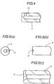
- a diameter of a circle formed by coupling the outer side surfaces of these ribs 23 is formed so as to be almost same as the diameter of the cartridge main body 1. Furthermore, an engagement edge 24 having an end portion bent inside so as to have a small diameter is formed at the tip end of the adaptor sleeve 18. The tip end of the ejection nozzle 4 is provided so as to protrude outward than the opening end of the adaptor sleeve 18.
- a cap 30 is provided at the adaptor sleeve 18 so as to be detachable freely.
- the cap 30 acts to cover the inner plate 20 and the ejection nozzle 4 to thereby protect these members from an external force and dust and prevent the fuel gas from being erroneously ejected.
- the inner diameter of the cap 30 is set so as to be slightly larger than the outer diameter of the bottom portion of the fuel cartridge A.
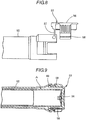
- An engagement groove 31 capable of engaging with the flange portion 22 of the adaptor sleeve 18 is formed at the inner peripheral surface of the opening end portion of the cap 30.
- a needle portion 32 capable of being inserted inside of the ejection nozzle 4 from the tip end thereof is formed at the center portion of the inside of the cap 30.
- the cartridge main body 1 is provided with the adaptor sleeve 18 at the outer periphery of the ejection nozzle 4, the ejection nozzle 4 can be protected from the external force applied from the periphery.
- the supply hole 17 of the ejection nozzle 4 is sufficient so long as it has a structure capable of exhausting the fuel gas at the side direction of the ejection nozzle 4.
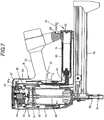
- a sign B shows the driving tool (nailing machine) and 34 denotes the tool main body.
- a grip 35 and a magazine 36 are coupled to the tool main body 34, and a combustion chamber 37 and a striking mechanism are provided within the tool main body.
- a nose portion 38 for driving a nail out is provided beneath the tool main body 34, and the magazine 36 for supplying nails is coupled to the nose portion 38.
- a cylinder head portion 44 is provided with an ignition plug (not shown), a rotary fan 46 and a fuel injection nozzle 45.
- the ignition plug ignites mixed gas of the fuel gas and the air within the combustion chamber 37 to combust the mixed gas.
- the rotary fan 46 acts to stir and mix the fuel gas and the air and is disposed at the center of a movable sleeve 47.
- 48 denotes a motor for driving the rotary fan 46.
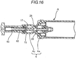
- the opening/closing mechanism 3 of the fuel cartridge A can be opened simultaneously with the pushing and loading of the fuel cartridge A into the housing portion 52, then the fuel gas can be ejected from the ejection nozzle 4 and supplied to the coupling sleeve 61, and further the fuel gas can always be supplied to the fuel measuring device 50 from the coupling sleeve 61.
- a predetermined amount of the fuel gas measured by the fuel measuring device 50 is supplied to the combustion chamber, then ignited and combusted, whereby the striking mechanism is driven.
Landscapes
- Engineering & Computer Science (AREA)
- Chemical & Material Sciences (AREA)
- Mechanical Engineering (AREA)
- Combustion & Propulsion (AREA)
- Dispersion Chemistry (AREA)
- General Engineering & Computer Science (AREA)
- Portable Nailing Machines And Staplers (AREA)
- Filling Or Discharging Of Gas Storage Vessels (AREA)
Claims (15)
- Brennstoffkartusche, die ausgelegt ist, um an einem Werkzeughauptkörper eines mit Verbrennungsgas betriebenen Antriebwerkzeugs befestigt zu werden, um so Brennstoff zu einem Schlagmechanismus des Werkzeughauptkörpers zuzuführen, wobei die Brennstoffkartusche umfasst:eine Ausstoßdüse (4), die an einem Anschlussbereich, der an einem Endbereich eines Kartuschenhauptkörpers (1) ausgebildet ist, vorgesehen und bezüglich des Kartuschenhauptkörpers (1) verschiebbar vorgesehen ist;eine Kompressionsfeder (16) zum Vorspannen der Ausstoßdüse (4) so dass ein vorderes Ende der Ausstoßdüse (4) von dem Kartuschenhauptkörper (1) vorsteht;eine Ausstoßöffnung (17), die an einer Seitenwand des vorderen Endbereichs der Ausstoßdüse (4) ausgebildet ist;eine Adapterhülse (18), die an einem Umfang der Ausstoßdüse (4) vorgesehen ist;gekennzeichnet übereine innere Platte (20), die innerhalb der Adapterhülse (18) bezüglich der Ausstoßdüse (4) verschiebbar vorgesehen ist und eine Einpassöffnung (25) umfasst, die mit der Ausstoßdüse zusammenpasst,wobei in einem Standby-Modus die innere Platte (20) mit einer Eingriffskante der Adapterhülse (18) derart in Eingriff steht, dass eine Vorsprungskante (28), die an einem äußeren Umfangsende der inneren Platte (20) ausgebildet ist, mit der Eingriffskante (24) der Adapterhülse (18) in Eingriff steht.
- Brennstoffkartusche gemäß Anspruch 1, bei der die Kompressionsfeder (16) die Ausstoßdüse (4) in eine axiale Richtung der Ausstoßdüse (4) vorspannt, und
eine Richtung, in der die Ausstoßöffnung (17) sich erstreckt, die axiale Richtung der Ausstoßdüse (4) schneidet. - Brennstoffkartusche gemäß Anspruch 1, weiter umfassend ein Ventil, das an dem Anschlussbereich angeordnet ist, wobei sich das Ventil öffnet, wenn sich die Ausstoßdüse (4) gegen eine Vorspannkraft der Feder (16) verschiebt.
- Brennstoffkartusche gemäß Anspruch 3, bei der das vordere Ende der Ausstoßdüse (4) nach außen von einem Öffnungsende der Adapterhülse (18) vorsteht.
- Brennstoffkartusche gemäß Anspruch 3, bei der die innere Platte (20) in eine Richtung eines Vorstehens zu einer Außenseite der Adapterhülse (18) vorgespannt ist.
- Brennstoffkartusche gemäß Anspruch 5, weiter umfassend einen Führungsbereich, der an der inneren Platte (20) vorgesehen ist und für ein Führen eines Kopplungsabschnitt (54) in dem Werkzeughauptkörper zu der Ausstoßdüse (4).
- Brennstoffkartusche gemäß Anspruch 5, bei der die innere Platte (20) derart vorgespannt ist, um weiter nach außen vorzustehen als ein Öffnungsende der Adapterhülse (18).
- Brennstoffkartusche gemäß Anspruch 5, bei der die Kompressionsfeder (16), die innere Platte (20) und die Adapterhülse (18) koaxial zu der Ausstoßdüse (4) angeordnet sind.
- Brennstoffkartusche gemäß Anspruch 5, weiter umfassend eine Abdeckung zum Abdecken der inneren Platte (20) und der Ausstoßdüse (4) und die abnehmbar an der Adapterhülse (18) befestigt ist,
wobei die Abdeckung einen Nadelbereich (32) umfasst, der ausgelegt ist, um ins Innere der Ausstoßdüse (4) von einem vorderen Ende der Ausstoßdüse (4) an einem Mittenbereich von einer Innenseite der Abdeckung eingeführt zu werden, und
ein innerer Durchmesser der Abdeckung geringfügig größer ist als ein äußerer Durchmesser von einem Bodenbereich der Brennstoffkartusche. - Verbrennungsgas betriebenes Antriebswerkzeug umfassend:einen Gehäusebereich (52), der ausgelegt ist für ein Laden einer Brennstoffkartusche von einem Ende des Gehäuseabschnitts (52), wobei die Brennstoffkartusche eine Ausstoßdüse (4) umfasst, die über eine erste Kompressionsfeder (16) vorgespannt ist und Verbrennungsgas abgegeben wird, wenn die Ausstoßdüse (4) bezüglich eines Kartuschenhauptkörpers (1) gegen eine Spannkraft der ersten Kompressionsfeder (16) gedrängt ist/wird;dadurch gekennzeichnet, dass es umfasst:eine Kopplungshülse (61), die an dem anderen Ende von dem Gehäusebereich (52) vorgesehen ist und ausgelegt ist für ein Einführen der Ausstoßdüse (4) von der Brennstoffkartusche darin;einen Düsenkolben (62), der verschiebbar innerhalb der Kopplungshülse (61) aufgenommen ist und für ein Abstützen an einem vorderen Ende der Ausstoßdüse (4) ausgelegt ist;eine zweite Kompressionsfeder (70) zum Vorspannen des Düsenkolbens (62) gegen eine vordere Endbereichsseite von der Kopplungshülse (61);eine Adapterhülse (18), die an einem Umfang der Ausstoßdüse (4) vorgesehen ist; undeine innere Platte (20), die innerhalb der Adapterhülse (18) verschiebbar vorgesehen ist und einer Einpassöffnung (25) umfasst, die mit der Ausstoßdüse (4) zusammenpasst,wobei, in einem Standby-Modus die innere Platte (20) mit einer Eingriffskante der Adapterhülse (18) derart in Eingriff steht, dass eine Vorsprungskante, die an einem äußeren Umfangsende der inneren Platte (20) ausgebildet ist, mit der Eingriffskante der Adapterhülse (18) in Eingriff steht,wobei eine Vorspannkraft der zweiten Kompressionsfeder (70) geringer ist als die Vorspannkraft der ersten Kompressionsfeder (16), undwobei, nachdem die Brennstoffkartusche in den Gehäusebereich (52) gedrängt ist, um den Düsenkolben über die erste Kompressionsfeder (16) nach hinten zu einem bewegbarene Ende davon zu bewegen, wenn die Brennstoffkartusche weiter hineingeschoben wird, der Düsenkolben in die Ausstoßdüse (4) hineindrängt, so dass Verbrennungsgas von der Ausstoßdüse (4) abgegeben wird und zu einer Seite von der Kopplungshülse (61) zugeführt wird.
- Antriebswerkzeug gemäß Anspruch 10, bei dem ein vorderes Ende des Düsenkolbens in einer axialen Richtung des Düsenkolbens geschlossen ist,
der Düsenkolben eine Einführungsöffnung umfasst, die sich in eine Richtung, die die axiale Richtung schneidet, erstreckt und nahe zu dem vorderen Endbereich ausgebildet ist,
zwei Dichtelemente (65, 66), die an einer inneren Umfangsfläche der Kopplungshülse (61) mit einem Abstand dazwischen vorgesehen sind, und
wenn eine Ausstoßöffnung der Ausstoßdüse (4), die sich in eine Richtung erstreckt, die die axiale Richtung schneidet, und die Einführungsöffnung zwischen den Dichtelementen angeordnet sind, Verbrennungsgas von der Ausstoßöffnung zu der Einführungsöffnung zugeführt ist. - Antriebswerkzeug gemäß Anspruch 10, bei dem ein vorderes Ende des Düsenkolbens in einer axialen Richtung des Düsenkolbens geschlossen ist,
zwei Dichtelemente an einer inneren Umfangsfläche der Kopplungshülse mit einem Abstand dazwischen vorgesehen sind,
eine Einführungsöffnung, die eine Seitenwand der Kopplungshülse durchdringt, zwischen den Dichtelementen ausgebildet ist, und
wenn eine Ausstoßöffnung der Ausstoßdüse (4), die sich in einer Richtung erstreckt, die die axiale Richtung schneidet, zwischen den Dichtelementen angeordnet ist, das Verbrennungsgas von der Ausstoßöffnung zu der Einführungsöffnung zugeführt wird. - Antriebswerkzeug gemäß Anspruch 10, bei dem der Werkzeughauptkörper mit einer Brennstoffmessvorrichtung (50) vorgesehen ist.
- Antriebswerkzeug gemäß Anspruch 10, bei dem der Kartuschenhauptkörper (1) mit einer Adapterhülse (18) an einem Umfang der Austoßdüse (4) vorgesehen ist,
eine innere Platte (20) mit einer Einpassöffnung, die die auf die Ausstoßdüse (4) passt, verschiebbar innerhalb der Adapterhülse (18) vorgesehen ist, und
die innere Platte (20) in eine Richtung eines Vorstehens zu einer Außenseite der Adapterhülse (18) vorgespannt ist. - Antriebswerkzeug gemäß Anspruch 10, bei dem ein staubdichtes Dichtelement, das mit dem Düsenkolben (62) in Kontakt steht, in einem Standby-Zustand, an einer inneren Umfangsfläche des Endbereichs der Kopplungshülse (61) vorgesehen ist, um Staub von einem Eindringen von einem Endbereich der Kopplungshülse (61) abzuhalten.
Priority Applications (1)
| Application Number | Priority Date | Filing Date | Title |
|---|---|---|---|
| PL14001374T PL2767366T3 (pl) | 2008-05-16 | 2009-04-27 | Wkład paliwowy |
Applications Claiming Priority (3)
| Application Number | Priority Date | Filing Date | Title |
|---|---|---|---|
| JP2008129721A JP5104536B2 (ja) | 2008-05-16 | 2008-05-16 | 燃料充填容器及びガス燃焼式打込み工具 |
| EP12000470.0A EP2447009B1 (de) | 2008-05-16 | 2009-04-27 | Brennstoffkartusche |
| EP09005842A EP2119535B1 (de) | 2008-05-16 | 2009-04-27 | Gasverbrennungsantriebseinheit |
Related Parent Applications (3)
| Application Number | Title | Priority Date | Filing Date |
|---|---|---|---|
| EP12000470.0A Division-Into EP2447009B1 (de) | 2008-05-16 | 2009-04-27 | Brennstoffkartusche |
| EP12000470.0A Division EP2447009B1 (de) | 2008-05-16 | 2009-04-27 | Brennstoffkartusche |
| EP09005842A Division EP2119535B1 (de) | 2008-05-16 | 2009-04-27 | Gasverbrennungsantriebseinheit |
Publications (2)
| Publication Number | Publication Date |
|---|---|
| EP2767366A1 EP2767366A1 (de) | 2014-08-20 |
| EP2767366B1 true EP2767366B1 (de) | 2018-01-17 |
Family
ID=40996514
Family Applications (3)
| Application Number | Title | Priority Date | Filing Date |
|---|---|---|---|
| EP14001374.9A Active EP2767366B1 (de) | 2008-05-16 | 2009-04-27 | Brennstoffkartusche |
| EP09005842A Active EP2119535B1 (de) | 2008-05-16 | 2009-04-27 | Gasverbrennungsantriebseinheit |
| EP12000470.0A Active EP2447009B1 (de) | 2008-05-16 | 2009-04-27 | Brennstoffkartusche |
Family Applications After (2)
| Application Number | Title | Priority Date | Filing Date |
|---|---|---|---|
| EP09005842A Active EP2119535B1 (de) | 2008-05-16 | 2009-04-27 | Gasverbrennungsantriebseinheit |
| EP12000470.0A Active EP2447009B1 (de) | 2008-05-16 | 2009-04-27 | Brennstoffkartusche |
Country Status (9)
| Country | Link |
|---|---|
| US (2) | US8505796B2 (de) |
| EP (3) | EP2767366B1 (de) |
| JP (1) | JP5104536B2 (de) |
| KR (1) | KR20090119730A (de) |
| CN (3) | CN104149072B (de) |
| AU (1) | AU2009201781A1 (de) |
| CA (1) | CA2665059A1 (de) |
| PL (1) | PL2767366T3 (de) |
| TW (1) | TWI520819B (de) |
Families Citing this family (21)
| Publication number | Priority date | Publication date | Assignee | Title |
|---|---|---|---|---|
| JP5104536B2 (ja) | 2008-05-16 | 2012-12-19 | マックス株式会社 | 燃料充填容器及びガス燃焼式打込み工具 |
| JP5431975B2 (ja) * | 2010-01-07 | 2014-03-05 | 株式会社マキタ | 電動工具 |
| JP5494342B2 (ja) * | 2010-08-12 | 2014-05-14 | マックス株式会社 | 燃料容器取付構造 |
| JP5817126B2 (ja) * | 2011-01-21 | 2015-11-18 | マックス株式会社 | 駆動工具 |
| JP5652262B2 (ja) * | 2011-03-02 | 2015-01-14 | マックス株式会社 | ガス燃焼式打ち込み工具 |
| FR2972666B1 (fr) * | 2011-03-16 | 2014-04-25 | Prospection & Inventions | Outil de scellement a gaz a perte de combustible limitee |
| JP5741233B2 (ja) * | 2011-06-10 | 2015-07-01 | マックス株式会社 | 燃料容器保持構造 |
| ITVR20120107A1 (it) * | 2012-05-24 | 2013-11-25 | Cavagna Group Spa | Dispositivo di protezione |
| JP5578206B2 (ja) * | 2012-08-03 | 2014-08-27 | マックス株式会社 | 燃料充填容器及びガス燃焼式打込み工具 |
| BE1020822A3 (nl) * | 2012-08-13 | 2014-05-06 | Proco Sys Bv Met Beperkte Aansprakelijkheid | Patroon voor het verdelen van een onder druk staande vloeistof en gebruik daarvan. |
| US10385285B2 (en) | 2015-02-25 | 2019-08-20 | Illinois Tool Works Inc. | Fuel and propellant composition for combustion tools |
| TWM518150U (zh) * | 2015-10-14 | 2016-03-01 | Basso Ind Corp | 瓦斯釘槍及其燃料傳輸裝置 |
| US10598377B2 (en) | 2016-05-27 | 2020-03-24 | Illinois Tool Works Inc. | Combustion-powered fastener driving tool fuel cell assembly |
| CN106882761B (zh) * | 2017-03-01 | 2022-11-04 | 武汉大汉口食品有限公司 | 一种用于存放液态酱料出料装置 |
| WO2018231650A1 (en) * | 2017-06-16 | 2018-12-20 | Wine Plum, Inc. | Liquid dispensing device |
| WO2019071237A1 (en) | 2017-10-06 | 2019-04-11 | Black & Decker Inc. | HYDROGEN FUEL CARTRIDGE |
| CN109202810B (zh) * | 2018-10-05 | 2024-03-19 | 宜宾市南溪区鑫盛技术开发有限公司 | 自动排渣散热式轴向射钉器 |
| CN109529409B (zh) * | 2018-12-10 | 2024-03-08 | 浙江金仪盛世生物工程有限公司 | 双工位喷头 |
| FR3107584B1 (fr) | 2020-02-24 | 2022-06-24 | Plastic Omnium Advanced Innovation & Res | Dispositif d’obstruction automatique d’un circuit de remplissage d’un ou plusieurs réservoir(s) d’un fluide |
| GB202102406D0 (en) * | 2021-02-19 | 2021-04-07 | Sympafix Bv | Combustion-powered fastener driving tool fuel supply canisters and fuel supply canister valve assemblies |
| TWI766825B (zh) * | 2021-12-03 | 2022-06-01 | 穆思嘉 | 無線氣動釘槍 |
Family Cites Families (47)
| Publication number | Priority date | Publication date | Assignee | Title |
|---|---|---|---|---|
| DE1183732B (de) * | 1963-07-15 | 1964-12-17 | Wieden & Co G M B H | Fuellventil fuer Gasfeuerzeuge |
| IT957974B (it) | 1971-05-27 | 1973-10-20 | Visscher P De | Perfezionamento nei raccordi o giunti per il collegamento di ambienti |
| US4331277A (en) * | 1980-05-23 | 1982-05-25 | United States Surgical Corporation | Self-contained gas powered surgical stapler |
| US4483474A (en) * | 1981-01-22 | 1984-11-20 | Signode Corporation | Combustion gas-powered fastener driving tool |
| DE3425092A1 (de) * | 1984-07-07 | 1986-02-06 | SMS Schloemann-Siemag AG, 4000 Düsseldorf | Verfahren und vorrichtung zum kuehlen von kontinuierlich gefoerderten giessstraengen in einer stranggiessanlage |
| US4742548A (en) | 1984-12-20 | 1988-05-03 | American Telephone And Telegraph Company | Unidirectional second order gradient microphone |
| JPS61150600U (de) * | 1985-03-11 | 1986-09-17 | ||
| US4739915A (en) * | 1986-07-02 | 1988-04-26 | Senco Products, Inc. | Simplified self-contained internal combustion fastener driving tool |
| FR2617941B1 (fr) * | 1987-07-07 | 1989-10-27 | Applic Gaz Sa | Valve et recipient a valve |
| US5115944A (en) * | 1990-08-14 | 1992-05-26 | Illinois Tool Works Inc. | Fluid dispenser having a collapsible inner bag |
| AU5883694A (en) * | 1993-01-19 | 1994-08-15 | Glaxo Group Limited | Device |
| JPH06220910A (ja) * | 1993-01-26 | 1994-08-09 | Hiroshima Jiyousui:Kk | 管の超高圧洗浄用ノズル |
| ATE171440T1 (de) * | 1993-12-06 | 1998-10-15 | Charles Kaeser | Wiederfüllbarer aerosolbehälter mit luft als treibmittel |
| JP2962988B2 (ja) * | 1993-12-28 | 1999-10-12 | シャープ株式会社 | 液体燃料燃焼器の燃料供給装置 |
| GB9414236D0 (en) * | 1994-07-14 | 1994-08-31 | V A R I S P A | Aerosol metering valves |
| GB9626960D0 (en) * | 1996-12-27 | 1997-02-12 | Glaxo Group Ltd | Valve for aerosol container |
| GB9703004D0 (en) * | 1997-02-13 | 1997-04-02 | Guest John Eng | Improvements in or relating to connectors for coupling tubes |
| JPH11101400A (ja) * | 1997-09-30 | 1999-04-13 | Nippon Gas Co Ltd | カセット式ガスボンベ |
| US6145724A (en) | 1997-10-31 | 2000-11-14 | Illinois Tool Works, Inc. | Combustion powered tool with combustion chamber delay |
| US5909836A (en) | 1997-10-31 | 1999-06-08 | Illinois Tool Works Inc. | Combustion powered tool with combustion chamber lockout |
| FR2771796B1 (fr) * | 1997-11-28 | 2000-01-14 | Spit Soc Prospect Inv Techn | Raccord pour appareil de fixation a gaz comprime et cartouche de gaz comprime |
| FR2774934B1 (fr) * | 1998-02-13 | 2000-03-31 | Spit Soc Prospect Inv Techn | Appareil de fixation a gaz comprime |
| GB9805938D0 (en) * | 1998-03-19 | 1998-05-13 | Glaxo Group Ltd | Valve for aerosol container |
| DE19950350C2 (de) * | 1999-10-19 | 2002-06-20 | Hilti Ag | Dosierkopf, insbesondere für brennkraftbetriebene Setzgeräte |
| FR2804666B1 (fr) * | 2000-02-04 | 2002-06-14 | Oreal | Distributeur pour le stockage d'au moins deux composants et la distribution selective soit d'un constituant seul, soit de leur melange, et procede pour sa mise en oeuvre |
| US6302297B1 (en) * | 2000-09-06 | 2001-10-16 | Illinois Tool Works Inc. | External metering valve for a fuel cell |
| US6439430B1 (en) * | 2000-09-22 | 2002-08-27 | Summit Packaging Systems, Inc. | Collapsible bag, aerosol container incorporating same and method of assembling aerosol container |
| US6523860B1 (en) * | 2000-10-12 | 2003-02-25 | Illinois Tool Works Inc. | Fuel cell adapter system for combustion tools |
| JP2002362603A (ja) * | 2001-06-06 | 2002-12-18 | Kitano Seisaku Kk | 目薬用容器 |
| DE20114780U1 (de) * | 2001-09-06 | 2002-01-17 | Kersten, Olaf, Dr.-Ing., 47802 Krefeld | Zweikammersystem mit Dosierventil |
| US7392922B2 (en) * | 2004-04-19 | 2008-07-01 | Illinois Tool Works Inc. | In-can fuel cell metering valve |
| US7478740B2 (en) * | 2006-06-30 | 2009-01-20 | Illinois Tool Works Inc. | Enhanced fuel passageway and adapter for combustion tool fuel cell |
| FR2870921B1 (fr) * | 2004-05-25 | 2007-07-06 | Prospection Et D Inv S Techniq | Adaptateur de raccordement d'une cartouche de gaz et d'un dispositif d'admission de gaz d'un appareil de fixation a gaz, la cartouche, l'electrovanne et l'appareil avec l'adaptateur |
| JP4271084B2 (ja) * | 2004-06-01 | 2009-06-03 | 株式会社マキタ | 燃焼式作業工具 |
| JP4587710B2 (ja) | 2004-06-03 | 2010-11-24 | 小川香料株式会社 | 抗菌剤組成物 |
| JP4768236B2 (ja) * | 2004-06-15 | 2011-09-07 | 株式会社日立製作所 | 燃料電池、その燃料供給システム、燃料カートリッジ並びに電子機器 |
| JP4590226B2 (ja) * | 2004-07-30 | 2010-12-01 | 株式会社東海 | コネクタ構造 |
| JP4492310B2 (ja) | 2004-11-25 | 2010-06-30 | 日立工機株式会社 | 燃料ガス、該燃料ガスにより駆動する燃焼式動力工具および燃焼式動力工具用ガスボンベ |
| JP2006253040A (ja) * | 2005-03-11 | 2006-09-21 | Toshiba Corp | 燃料容器及び燃料電池システム |
| JP4923436B2 (ja) * | 2005-05-10 | 2012-04-25 | マックス株式会社 | ガス燃焼式打込み工具 |
| JP4877457B2 (ja) * | 2005-05-17 | 2012-02-15 | マックス株式会社 | ガス燃焼式打込み工具における釘送り作動遅延機構 |
| JP5223186B2 (ja) * | 2006-01-27 | 2013-06-26 | マックス株式会社 | ガスカートリッジ |
| US7296719B1 (en) * | 2006-04-26 | 2007-11-20 | Illinois Tool Works Inc. | Fuel cell actuator and associated combustion tool |
| JP4465392B2 (ja) * | 2008-01-30 | 2010-05-19 | 株式会社日本製鋼所 | カプラ及びガス又は液体の供給装置 |
| JP5104536B2 (ja) | 2008-05-16 | 2012-12-19 | マックス株式会社 | 燃料充填容器及びガス燃焼式打込み工具 |
| US8302831B2 (en) * | 2010-04-13 | 2012-11-06 | Illinois Tool Works Inc. | Flanged fuel cell and locating structure for combustion tool |
| US8939339B2 (en) * | 2010-04-13 | 2015-01-27 | Illinois Tool Works Inc. | Interface for fuel delivery system for combustion nailer |
-
2008
- 2008-05-16 JP JP2008129721A patent/JP5104536B2/ja active Active
-
2009
- 2009-04-24 TW TW098113585A patent/TWI520819B/zh active
- 2009-04-27 EP EP14001374.9A patent/EP2767366B1/de active Active
- 2009-04-27 EP EP09005842A patent/EP2119535B1/de active Active
- 2009-04-27 EP EP12000470.0A patent/EP2447009B1/de active Active
- 2009-04-27 PL PL14001374T patent/PL2767366T3/pl unknown
- 2009-04-30 CA CA002665059A patent/CA2665059A1/en not_active Abandoned
- 2009-05-04 AU AU2009201781A patent/AU2009201781A1/en not_active Abandoned
- 2009-05-12 US US12/464,271 patent/US8505796B2/en active Active
- 2009-05-15 KR KR1020090042314A patent/KR20090119730A/ko not_active Withdrawn
- 2009-05-18 CN CN201410333776.5A patent/CN104149072B/zh active Active
- 2009-05-18 CN CN200910141043.0A patent/CN101579848B/zh active Active
- 2009-05-18 CN CN201410018213.7A patent/CN103753500B/zh active Active
-
2013
- 2013-08-07 US US13/961,431 patent/US9381636B2/en active Active
Non-Patent Citations (1)
| Title |
|---|
| None * |
Also Published As
| Publication number | Publication date |
|---|---|
| CN103753500B (zh) | 2016-05-04 |
| EP2447009B1 (de) | 2014-06-25 |
| EP2119535A1 (de) | 2009-11-18 |
| US20090283567A1 (en) | 2009-11-19 |
| CN104149072A (zh) | 2014-11-19 |
| CN103753500A (zh) | 2014-04-30 |
| EP2447009A1 (de) | 2012-05-02 |
| CN104149072B (zh) | 2016-08-24 |
| TW201006630A (en) | 2010-02-16 |
| JP5104536B2 (ja) | 2012-12-19 |
| US20130320061A1 (en) | 2013-12-05 |
| PL2767366T3 (pl) | 2018-06-29 |
| JP2009275874A (ja) | 2009-11-26 |
| US9381636B2 (en) | 2016-07-05 |
| CA2665059A1 (en) | 2009-11-16 |
| US8505796B2 (en) | 2013-08-13 |
| CN101579848B (zh) | 2014-08-20 |
| KR20090119730A (ko) | 2009-11-19 |
| CN101579848A (zh) | 2009-11-18 |
| EP2119535B1 (de) | 2013-03-20 |
| EP2767366A1 (de) | 2014-08-20 |
| AU2009201781A1 (en) | 2009-12-03 |
| TWI520819B (zh) | 2016-02-11 |
Similar Documents
| Publication | Publication Date | Title |
|---|---|---|
| EP2119535B1 (de) | Gasverbrennungsantriebseinheit | |
| EP1914041B1 (de) | Gasverbrennungskraftbetriebenes eintreibwerkzeug | |
| JP4923436B2 (ja) | ガス燃焼式打込み工具 | |
| US7938303B2 (en) | Gas combustion-type driving tool | |
| US7175063B2 (en) | Powered nailing machine | |
| JP2001138264A (ja) | 固定素子用の打ち込み装置 | |
| US7416100B2 (en) | Setting tool | |
| EP2532483B1 (de) | Haltestruktur für einen Kraftstoffbehälter | |
| WO2009096395A1 (ja) | 釘打機 | |
| JP4780282B2 (ja) | ガス燃焼式打込み工具におけるファスナー送り作動遅延機構 | |
| JP5578206B2 (ja) | 燃料充填容器及びガス燃焼式打込み工具 | |
| JP2009297839A (ja) | ガス燃焼式打込み工具 | |
| JPH0616671Y2 (ja) | 釘打機における安全装置 |
Legal Events
| Date | Code | Title | Description |
|---|---|---|---|
| PUAI | Public reference made under article 153(3) epc to a published international application that has entered the european phase |
Free format text: ORIGINAL CODE: 0009012 |
|
| 17P | Request for examination filed |
Effective date: 20140415 |
|
| AC | Divisional application: reference to earlier application |
Ref document number: 2447009 Country of ref document: EP Kind code of ref document: P Ref document number: 2119535 Country of ref document: EP Kind code of ref document: P |
|
| AK | Designated contracting states |
Kind code of ref document: A1 Designated state(s): AT BE BG CH CY CZ DE DK EE ES FI FR GB GR HR HU IE IS IT LI LT LU LV MC MK MT NL NO PL PT RO SE SI SK TR |
|
| GRAP | Despatch of communication of intention to grant a patent |
Free format text: ORIGINAL CODE: EPIDOSNIGR1 |
|
| INTG | Intention to grant announced |
Effective date: 20170801 |
|
| GRAS | Grant fee paid |
Free format text: ORIGINAL CODE: EPIDOSNIGR3 |
|
| GRAA | (expected) grant |
Free format text: ORIGINAL CODE: 0009210 |
|
| AC | Divisional application: reference to earlier application |
Ref document number: 2119535 Country of ref document: EP Kind code of ref document: P Ref document number: 2447009 Country of ref document: EP Kind code of ref document: P |
|
| AK | Designated contracting states |
Kind code of ref document: B1 Designated state(s): AT BE BG CH CY CZ DE DK EE ES FI FR GB GR HR HU IE IS IT LI LT LU LV MC MK MT NL NO PL PT RO SE SI SK TR |
|
| REG | Reference to a national code |
Ref country code: GB Ref legal event code: FG4D |
|
| REG | Reference to a national code |
Ref country code: CH Ref legal event code: EP Ref country code: CH Ref legal event code: NV Representative=s name: BOVARD AG PATENT- UND MARKENANWAELTE, CH |
|
| REG | Reference to a national code |
Ref country code: IE Ref legal event code: FG4D |
|
| REG | Reference to a national code |
Ref country code: AT Ref legal event code: REF Ref document number: 964097 Country of ref document: AT Kind code of ref document: T Effective date: 20180215 |
|
| REG | Reference to a national code |
Ref country code: DE Ref legal event code: R096 Ref document number: 602009050496 Country of ref document: DE |
|
| REG | Reference to a national code |
Ref country code: NL Ref legal event code: FP |
|
| REG | Reference to a national code |
Ref country code: LT Ref legal event code: MG4D |
|
| REG | Reference to a national code |
Ref country code: AT Ref legal event code: MK05 Ref document number: 964097 Country of ref document: AT Kind code of ref document: T Effective date: 20180117 |
|
| PG25 | Lapsed in a contracting state [announced via postgrant information from national office to epo] |
Ref country code: FI Free format text: LAPSE BECAUSE OF FAILURE TO SUBMIT A TRANSLATION OF THE DESCRIPTION OR TO PAY THE FEE WITHIN THE PRESCRIBED TIME-LIMIT Effective date: 20180117 Ref country code: NO Free format text: LAPSE BECAUSE OF FAILURE TO SUBMIT A TRANSLATION OF THE DESCRIPTION OR TO PAY THE FEE WITHIN THE PRESCRIBED TIME-LIMIT Effective date: 20180417 Ref country code: HR Free format text: LAPSE BECAUSE OF FAILURE TO SUBMIT A TRANSLATION OF THE DESCRIPTION OR TO PAY THE FEE WITHIN THE PRESCRIBED TIME-LIMIT Effective date: 20180117 Ref country code: CY Free format text: LAPSE BECAUSE OF FAILURE TO SUBMIT A TRANSLATION OF THE DESCRIPTION OR TO PAY THE FEE WITHIN THE PRESCRIBED TIME-LIMIT Effective date: 20180117 Ref country code: LT Free format text: LAPSE BECAUSE OF FAILURE TO SUBMIT A TRANSLATION OF THE DESCRIPTION OR TO PAY THE FEE WITHIN THE PRESCRIBED TIME-LIMIT Effective date: 20180117 Ref country code: ES Free format text: LAPSE BECAUSE OF FAILURE TO SUBMIT A TRANSLATION OF THE DESCRIPTION OR TO PAY THE FEE WITHIN THE PRESCRIBED TIME-LIMIT Effective date: 20180117 |
|
| PG25 | Lapsed in a contracting state [announced via postgrant information from national office to epo] |
Ref country code: IS Free format text: LAPSE BECAUSE OF FAILURE TO SUBMIT A TRANSLATION OF THE DESCRIPTION OR TO PAY THE FEE WITHIN THE PRESCRIBED TIME-LIMIT Effective date: 20180517 Ref country code: BG Free format text: LAPSE BECAUSE OF FAILURE TO SUBMIT A TRANSLATION OF THE DESCRIPTION OR TO PAY THE FEE WITHIN THE PRESCRIBED TIME-LIMIT Effective date: 20180417 Ref country code: GR Free format text: LAPSE BECAUSE OF FAILURE TO SUBMIT A TRANSLATION OF THE DESCRIPTION OR TO PAY THE FEE WITHIN THE PRESCRIBED TIME-LIMIT Effective date: 20180418 Ref country code: SE Free format text: LAPSE BECAUSE OF FAILURE TO SUBMIT A TRANSLATION OF THE DESCRIPTION OR TO PAY THE FEE WITHIN THE PRESCRIBED TIME-LIMIT Effective date: 20180117 Ref country code: LV Free format text: LAPSE BECAUSE OF FAILURE TO SUBMIT A TRANSLATION OF THE DESCRIPTION OR TO PAY THE FEE WITHIN THE PRESCRIBED TIME-LIMIT Effective date: 20180117 Ref country code: AT Free format text: LAPSE BECAUSE OF FAILURE TO SUBMIT A TRANSLATION OF THE DESCRIPTION OR TO PAY THE FEE WITHIN THE PRESCRIBED TIME-LIMIT Effective date: 20180117 |
|
| REG | Reference to a national code |
Ref country code: DE Ref legal event code: R097 Ref document number: 602009050496 Country of ref document: DE |
|
| PG25 | Lapsed in a contracting state [announced via postgrant information from national office to epo] |
Ref country code: RO Free format text: LAPSE BECAUSE OF FAILURE TO SUBMIT A TRANSLATION OF THE DESCRIPTION OR TO PAY THE FEE WITHIN THE PRESCRIBED TIME-LIMIT Effective date: 20180117 Ref country code: EE Free format text: LAPSE BECAUSE OF FAILURE TO SUBMIT A TRANSLATION OF THE DESCRIPTION OR TO PAY THE FEE WITHIN THE PRESCRIBED TIME-LIMIT Effective date: 20180117 Ref country code: IT Free format text: LAPSE BECAUSE OF FAILURE TO SUBMIT A TRANSLATION OF THE DESCRIPTION OR TO PAY THE FEE WITHIN THE PRESCRIBED TIME-LIMIT Effective date: 20180117 |
|
| PLBE | No opposition filed within time limit |
Free format text: ORIGINAL CODE: 0009261 |
|
| STAA | Information on the status of an ep patent application or granted ep patent |
Free format text: STATUS: NO OPPOSITION FILED WITHIN TIME LIMIT |
|
| PG25 | Lapsed in a contracting state [announced via postgrant information from national office to epo] |
Ref country code: MC Free format text: LAPSE BECAUSE OF FAILURE TO SUBMIT A TRANSLATION OF THE DESCRIPTION OR TO PAY THE FEE WITHIN THE PRESCRIBED TIME-LIMIT Effective date: 20180117 Ref country code: SK Free format text: LAPSE BECAUSE OF FAILURE TO SUBMIT A TRANSLATION OF THE DESCRIPTION OR TO PAY THE FEE WITHIN THE PRESCRIBED TIME-LIMIT Effective date: 20180117 Ref country code: CZ Free format text: LAPSE BECAUSE OF FAILURE TO SUBMIT A TRANSLATION OF THE DESCRIPTION OR TO PAY THE FEE WITHIN THE PRESCRIBED TIME-LIMIT Effective date: 20180117 Ref country code: DK Free format text: LAPSE BECAUSE OF FAILURE TO SUBMIT A TRANSLATION OF THE DESCRIPTION OR TO PAY THE FEE WITHIN THE PRESCRIBED TIME-LIMIT Effective date: 20180117 |
|
| REG | Reference to a national code |
Ref country code: BE Ref legal event code: MM Effective date: 20180430 |
|
| 26N | No opposition filed |
Effective date: 20181018 |
|
| GBPC | Gb: european patent ceased through non-payment of renewal fee |
Effective date: 20180427 |
|
| REG | Reference to a national code |
Ref country code: IE Ref legal event code: MM4A |
|
| PG25 | Lapsed in a contracting state [announced via postgrant information from national office to epo] |
Ref country code: LU Free format text: LAPSE BECAUSE OF NON-PAYMENT OF DUE FEES Effective date: 20180427 |
|
| PG25 | Lapsed in a contracting state [announced via postgrant information from national office to epo] |
Ref country code: BE Free format text: LAPSE BECAUSE OF NON-PAYMENT OF DUE FEES Effective date: 20180430 Ref country code: SI Free format text: LAPSE BECAUSE OF FAILURE TO SUBMIT A TRANSLATION OF THE DESCRIPTION OR TO PAY THE FEE WITHIN THE PRESCRIBED TIME-LIMIT Effective date: 20180117 Ref country code: GB Free format text: LAPSE BECAUSE OF NON-PAYMENT OF DUE FEES Effective date: 20180427 |
|
| PG25 | Lapsed in a contracting state [announced via postgrant information from national office to epo] |
Ref country code: IE Free format text: LAPSE BECAUSE OF NON-PAYMENT OF DUE FEES Effective date: 20180427 Ref country code: FR Free format text: LAPSE BECAUSE OF NON-PAYMENT OF DUE FEES Effective date: 20180430 |
|
| PG25 | Lapsed in a contracting state [announced via postgrant information from national office to epo] |
Ref country code: MT Free format text: LAPSE BECAUSE OF NON-PAYMENT OF DUE FEES Effective date: 20180427 |
|
| PG25 | Lapsed in a contracting state [announced via postgrant information from national office to epo] |
Ref country code: TR Free format text: LAPSE BECAUSE OF FAILURE TO SUBMIT A TRANSLATION OF THE DESCRIPTION OR TO PAY THE FEE WITHIN THE PRESCRIBED TIME-LIMIT Effective date: 20180117 |
|
| PG25 | Lapsed in a contracting state [announced via postgrant information from national office to epo] |
Ref country code: HU Free format text: LAPSE BECAUSE OF FAILURE TO SUBMIT A TRANSLATION OF THE DESCRIPTION OR TO PAY THE FEE WITHIN THE PRESCRIBED TIME-LIMIT; INVALID AB INITIO Effective date: 20090427 Ref country code: PT Free format text: LAPSE BECAUSE OF FAILURE TO SUBMIT A TRANSLATION OF THE DESCRIPTION OR TO PAY THE FEE WITHIN THE PRESCRIBED TIME-LIMIT Effective date: 20180117 |
|
| PG25 | Lapsed in a contracting state [announced via postgrant information from national office to epo] |
Ref country code: MK Free format text: LAPSE BECAUSE OF NON-PAYMENT OF DUE FEES Effective date: 20180117 |
|
| PGFP | Annual fee paid to national office [announced via postgrant information from national office to epo] |
Ref country code: NL Payment date: 20260317 Year of fee payment: 18 |
|
| PGFP | Annual fee paid to national office [announced via postgrant information from national office to epo] |
Ref country code: PL Payment date: 20260317 Year of fee payment: 18 |
|
| REG | Reference to a national code |
Ref country code: CH Ref legal event code: U11 Free format text: ST27 STATUS EVENT CODE: U-0-0-U10-U11 (AS PROVIDED BY THE NATIONAL OFFICE) Effective date: 20260501 |
|
| PGFP | Annual fee paid to national office [announced via postgrant information from national office to epo] |
Ref country code: DE Payment date: 20260305 Year of fee payment: 18 |
|
| PGFP | Annual fee paid to national office [announced via postgrant information from national office to epo] |
Ref country code: CH Payment date: 20260501 Year of fee payment: 18 |