EP2762456B1 - Methods for manufacturing glass fine particle deposit and glass base material - Google Patents
Methods for manufacturing glass fine particle deposit and glass base material Download PDFInfo
- Publication number
- EP2762456B1 EP2762456B1 EP12834881.0A EP12834881A EP2762456B1 EP 2762456 B1 EP2762456 B1 EP 2762456B1 EP 12834881 A EP12834881 A EP 12834881A EP 2762456 B1 EP2762456 B1 EP 2762456B1
- Authority
- EP
- European Patent Office
- Prior art keywords
- glass
- source material
- burner
- fine
- gas
- Prior art date
- Legal status (The legal status is an assumption and is not a legal conclusion. Google has not performed a legal analysis and makes no representation as to the accuracy of the status listed.)
- Active
Links
Images


Classifications
-
- C—CHEMISTRY; METALLURGY
- C03—GLASS; MINERAL OR SLAG WOOL
- C03B—MANUFACTURE, SHAPING, OR SUPPLEMENTARY PROCESSES
- C03B37/00—Manufacture or treatment of flakes, fibres, or filaments from softened glass, minerals, or slags
- C03B37/01—Manufacture of glass fibres or filaments
- C03B37/012—Manufacture of preforms for drawing fibres or filaments
- C03B37/014—Manufacture of preforms for drawing fibres or filaments made entirely or partially by chemical means, e.g. vapour phase deposition of bulk porous glass either by outside vapour deposition [OVD], or by outside vapour phase oxidation [OVPO] or by vapour axial deposition [VAD]
- C03B37/01413—Reactant delivery systems
- C03B37/0142—Reactant deposition burners
-
- C—CHEMISTRY; METALLURGY
- C03—GLASS; MINERAL OR SLAG WOOL
- C03B—MANUFACTURE, SHAPING, OR SUPPLEMENTARY PROCESSES
- C03B37/00—Manufacture or treatment of flakes, fibres, or filaments from softened glass, minerals, or slags
- C03B37/01—Manufacture of glass fibres or filaments
- C03B37/012—Manufacture of preforms for drawing fibres or filaments
- C03B37/014—Manufacture of preforms for drawing fibres or filaments made entirely or partially by chemical means, e.g. vapour phase deposition of bulk porous glass either by outside vapour deposition [OVD], or by outside vapour phase oxidation [OVPO] or by vapour axial deposition [VAD]
- C03B37/01413—Reactant delivery systems
-
- C—CHEMISTRY; METALLURGY
- C03—GLASS; MINERAL OR SLAG WOOL
- C03B—MANUFACTURE, SHAPING, OR SUPPLEMENTARY PROCESSES
- C03B2207/00—Glass deposition burners
- C03B2207/04—Multi-nested ports
- C03B2207/06—Concentric circular ports
-
- C—CHEMISTRY; METALLURGY
- C03—GLASS; MINERAL OR SLAG WOOL
- C03B—MANUFACTURE, SHAPING, OR SUPPLEMENTARY PROCESSES
- C03B2207/00—Glass deposition burners
- C03B2207/04—Multi-nested ports
- C03B2207/08—Recessed or protruding ports
-
- C—CHEMISTRY; METALLURGY
- C03—GLASS; MINERAL OR SLAG WOOL
- C03B—MANUFACTURE, SHAPING, OR SUPPLEMENTARY PROCESSES
- C03B2207/00—Glass deposition burners
- C03B2207/20—Specific substances in specified ports, e.g. all gas flows specified
-
- C—CHEMISTRY; METALLURGY
- C03—GLASS; MINERAL OR SLAG WOOL
- C03B—MANUFACTURE, SHAPING, OR SUPPLEMENTARY PROCESSES
- C03B2207/00—Glass deposition burners
- C03B2207/20—Specific substances in specified ports, e.g. all gas flows specified
- C03B2207/22—Inert gas details
-
- C—CHEMISTRY; METALLURGY
- C03—GLASS; MINERAL OR SLAG WOOL
- C03B—MANUFACTURE, SHAPING, OR SUPPLEMENTARY PROCESSES
- C03B2207/00—Glass deposition burners
- C03B2207/20—Specific substances in specified ports, e.g. all gas flows specified
- C03B2207/24—Multiple flame type, e.g. double-concentric flame
-
- C—CHEMISTRY; METALLURGY
- C03—GLASS; MINERAL OR SLAG WOOL
- C03B—MANUFACTURE, SHAPING, OR SUPPLEMENTARY PROCESSES
- C03B2207/00—Glass deposition burners
- C03B2207/80—Feeding the burner or the burner-heated deposition site
- C03B2207/81—Constructional details of the feed line, e.g. heating, insulation, material, manifolds, filters
-
- Y—GENERAL TAGGING OF NEW TECHNOLOGICAL DEVELOPMENTS; GENERAL TAGGING OF CROSS-SECTIONAL TECHNOLOGIES SPANNING OVER SEVERAL SECTIONS OF THE IPC; TECHNICAL SUBJECTS COVERED BY FORMER USPC CROSS-REFERENCE ART COLLECTIONS [XRACs] AND DIGESTS
- Y02—TECHNOLOGIES OR APPLICATIONS FOR MITIGATION OR ADAPTATION AGAINST CLIMATE CHANGE
- Y02P—CLIMATE CHANGE MITIGATION TECHNOLOGIES IN THE PRODUCTION OR PROCESSING OF GOODS
- Y02P40/00—Technologies relating to the processing of minerals
- Y02P40/50—Glass production, e.g. reusing waste heat during processing or shaping
- Y02P40/57—Improving the yield, e-g- reduction of reject rates
Definitions
- the present invention relates to a method for manufacturing a glass-fine-particle-deposited body in which glass fine particles are deposited on a starting rod by the VAD method (vapor phase axial deposition method), the OVD method (outside vapor deposition method), the MMD method (multi-burner multi-layer deposition method), or the like to manufacture the glass-fine-particle-deposited body, and a method for manufacturing a glass base material in which the glass-fine-particle-deposited body is heated to impart transparency.
- VAD method vapor phase axial deposition method
- the OVD method outside vapor deposition method
- MMD method multi-burner multi-layer deposition method
- a glass source material gas is introduced into a burner for forming glass fine particles through a pipe under reduced pressure with heating and vaporizing a glass source material, so that pipe temperature is, for example, controlled to 55°C and hence it becomes possible to use a pipe made of a vinyl chloride-based material having a heat-resistant temperature of 70°C.
- Patent Document 2 After a glass source material gas is discarded for a predetermined period of time prior to the start of glass fine particle deposition, the deposition of glass fine particles is started and the discarded amount of the source material gas, volume of the pipe, pressure of the pipe inside, and temperature of the pipe are controlled so as to satisfy a predetermined relationship among them, thereby intending to avoid occurrence of air bubbles and cloudiness in the glass base material.
- the pipe temperature is controlled to be 82°C or 85°C.
- Patent Document 3 as a method for suppressing unevenness which may occur on the surface of the glass-fine-particle-deposited body, it is described to keep the conduit pipe from a source material gas-generating device that supplies the source material gas to the burner at 90°C or higher all over the length using a heater and a heat insulating material but there exists no description of temperature gradient of the conduit pipe. Also, there is no description of Reynolds number of the source material gas flowing in the pipe. Moreover, there is no description of particle diameter and aggregation of particles. Furthermore, there is no description of Stokes number of the glass fine particles.
- Patent Document 4 as a method for improving a source material yield, there is described a method of introducing a gas into inner circumference of a hood placed at a tip of the burner flame to suppress the spreading of the flame.
- a method for manufacturing a glass-fine-particle-deposited body there is commonly known a method for manufacturing a glass-fine-particle-deposited body by a vapor-phase synthetic method such as the VAD method, the OVD method, or the MMD method.
- a vapor-phase synthetic method such as the VAD method, the OVD method, or the MMD method.
- the particle diameter of the glass fine particles for example, in Patent Document 5 in which a porous soot body obtained by the vapor-phase synthetic method is impregnated with a mixed liquid containing additive fine particles dispersed therein and is heated and subjected to transparency impartment to form a glass base material, it is described to control the particle diameter of an SiO 2 -based porous body to 500 to 1,000 nm.
- Patent Document 6 describes a manufacturing method in which glass fine particles prepared previously are introduced into the burner flame. It is described that the average particle diameter of the glass fine particles to be charged is preferably controlled to 0.2 ⁇ m or less.
- Patent Document 7 describes a manufacturing method in which a glass-fine-particle-molded body is sintered by microwave heating, and it is described that the average particle diameter of the glass fine particles is from 1 nm to 100 ⁇ m.
- EP 2 463 250 teaches a process for production of a TiO 2 -SiO 2 glass body, comprising a step of, when an annealing point of a TiO 2 -SiO 2 glass body after transparent vitrification is taken as T 1 (°C), holding the glass body after transparent vitrification in a temperature region of from T 1 -90°C to T 1 -220°C for 120 hours or more.
- US 4,604,118 describes a vapour phase method for the synthesis of MgO-Al2O3-SiO 2 products, including MgO-Al 2 O 3 -SiO 2 glasses of optical quality, wherein SiCl 4 , aluminium halide, and organometallic magnesium vapours are oxidised by flame oxidation and the oxides collected and sintered to glass or ceramic products.
- An added shield gas stream is provided during flame oxidation of the vapours to reduce or prevent MgCl 2 byproduct formation at the burner and in the product.
- An object of the present invention is to provide manufacturing methods of a glass-fine-particle-deposited body and a glass base material, the methods being capable of improving an adhering efficiency of the formed glass fine particles on a starting rod or a glass-fine-particle-deposited body.
- the method for manufacturing a glass-fine-particle-deposited body according to the invention capable of solving the above problem is a method for manufacturing a glass-fine-particle-deposited body, the method comprising a depositing step of heating and vaporizing a liquid glass source material placed in a source material container to form a glass source material gas, introducing the glass source material gas to a burner for producing glass-fine-particles from the source material container through a pipe, spouting the glass source material gas from the burner for producing glass-fine-particles, and depositing glass fine particles produced by a flame decomposition reaction (pyrolysis reaction, flame hydrolysis reaction, thermal oxidation reaction, or the like) of the glass source material gas on a starting rod in a reaction container to prepare a glass-fine-particle-deposited body, wherein at least a part of the pipe from the source material container to the burner for producing glass-fine-particles in the deposition step is temperature-controlled by a heating element so that the burner side has a higher temperature than the source material
- the method for manufacturing a glass-fine-particle-deposited body according to the invention may be further characterized in that at least a part of the pipe from the source material container to the burner for producing glass-fine-particles in the deposition step is controlled to a temperature of 100°C or higher by a heating element and also the Reynolds number of the glass source material gas flowing in the pipe from the source material container to the burner for producing glass-fine-particles is controlled to 2,000 or more.
- the method for manufacturing a glass-fine-particle-deposited body according to the invention may be further characterized in that the particle diameter of the glass fine particles in the deposition step is controlled to 10 (nm) or more and the glass fine particles are combined between the particles in the flame of the burner for producing glass-fine-particles to make the mass of the combined particle group 1.8 ⁇ 10 -17 (g) or more.
- the method for manufacturing a glass-fine-particle-deposited body according to the invention may be further characterized in that the temperature of the glass source material gas to be charged into the burner for producing glass-fine-particles in the deposition step is kept at 100°C or higher, the glass source material gas is chemically changed to silicon oxide gas (SiO 2 , SiO, etc.) within 700 mm from the glass source material gas-spouting port of the burner for producing glass-fine-particles.
- silicon oxide gas SiO 2 , SiO, etc.
- silicon oxide gas saturated vapor pressure of the silicon oxide gas (SiO 2 , SiO, etc.) or higher at the position of 20 mm from the glass source material gas-spouting port of the burner for producing glass-fine-particles.
- silicon oxide gas SiO 2 , SiO, etc.
- the "silicon oxide” described in this specification means a collective term for oxides of silicon, such as SiO 2 and SiO.
- the method for manufacturing a glass-fine-particle-deposited body according to the invention may be further characterized in that at least a part of the pipe from the source material container to the burner for producing glass-fine-particles in the deposition step is controlled to a temperature of 100°C or higher by a heating element and also the Stokes number of the glass fine particles produced by the burner for producing glass-fine-particles is controlled to 0.5 or more.
- the method for manufacturing a glass-fine-particle-deposited body according to the invention may be further characterized in that, in the deposition step, at least a part of the pipe from the source material container to the burner for producing glass-fine-particles is controlled to a temperature of 100°C or higher by a heating element and also the region of one third or less of the longitudinal direction from the end part at the pipe side in the burner for producing glass-fine-particles is controlled to a temperature of 100°C or higher by a heating element.
- the method for manufacturing a glass-fine-particle-deposited body the invention may be further characterized in that the heating element is a tape heater.
- the method for manufacturing a glass base material according to the invention may be further characterized in that a glass-fine-particle-deposited body is manufactured by the above-described method for manufacturing a glass-fine-particle-deposited body and the glass base material is manufactured via a transparency-imparting step in which the glass-fine-particle-deposited body prepared in the deposition step is heated to impart transparency.
- the method for manufacturing a glass base material according to the invention may be further characterized in that the glass-fine-particle-deposited body is manufactured by the OVD method, the VAD method, or the MMD method in the deposition step and the glass base material is manufactured via the transparency-imparting step.
- At least a part of the pipe from the source material container to the burner for producing glass-fine-particles is temperature-controlled by a heating element so that the burner side has a high temperature and temperature gradient becomes 25°C/m or more, so that the volume of the source material gas in the pipe expands as the gas flows from the source material container to the burner side and the flow rate of the source material gas is accelerated.
- inertial force of the glass fine particles produced in the burner flame is increased and the straight advancing ability of the glass fine particles is promoted, so that the glass fine particles are prone to drop out of the gas flow in the flame. Accordingly, the adhering efficiency of the glass fine particles on the starting rod and the glass-fine-particle-deposited body can be improved and thus an improvement in the source material yield can be achieved.
- At least a part of the pipe from the source material container to the burner for producing glass-fine-particles may be controlled to a temperature of 100°C or higher by a heating element and also the Reynolds number of the glass source material gas flowing in the pipe from the source material container to the burner for producing glass-fine-particles may be controlled to 2,000 or more, whereby the flow of the glass source material gas becomes turbulent and thus the source material gas flowing in the pipe travels a path length longer than the pipe length, so that the heating time of the source material gas is lengthened and the temperature of the source material gas can be easily elevated.
- the flame hydrolysis reaction is promoted in the burner flame, the number of the glass fine particles produced in the flame is increased, and the outer diameter of the glass fine particles is also increased. Moreover, the increase in the particle diameter promotes the aggregation (combination between particles) by turbulent diffusion. Owing to these effects, the inertial force of the glass fine particles is increased and the glass fine particles are prone to drop out of the flow of the flame gas, so that the adhering efficiency of the glass fine particles on the starting rod and the glass-fine-particle-deposited body can be improved.
- the particle diameter of the glass fine particles may be controlled to 10 (nm) or more and the glass fine particles may be combined between the particles (aggregated) in the flame of the burner for producing glass-fine-particles to make the mass of the combined particle group 1.8 ⁇ 10 -17 (g) or more.
- the adhering efficiency of the produced glass fine particles on the starting rod and the glass-fine-particle-deposited body can be improved.
- the temperature of the glass source material gas to be charged into the burner for producing glass-fine-particles may be kept at 100°C or higher, the glass source material gas may be chemically changed to silicon oxide gas within 700 mm from the glass source material gas-spouting port of the burner for producing glass-fine-particles, and also partial pressure of the chemically changed silicon oxide gas may be controlled to saturated vapor pressure of the silicon oxide gas or higher at the position of 20 mm from the glass source material gas-spouting port of the burner for producing glass-fine-particles.
- the glass source material gas is chemically changed to silicon oxide gas at a position near to the glass source material gas-spouting port of the burner, the partial pressure of the silicon oxide gas increases, so that the change from the silicon oxide gas to silicon oxide particles (solid) becomes easy and also the silicon oxide particles tend to have a larger diameter.
- the particles have a larger diameter, the glass fine particles are prone to drop out of the flow of the flame gas, so that the adhering efficiency of the glass fine particles on the starting rod and the glass-fine-particle-deposited body can be improved and thus an improvement in the source material yield can be achieved.
- At least a part of the pipe from the source material container to the burner for producing glass-fine-particles may be controlled to a temperature of 100°C or higher by a heating element and also the Stokes number of the glass fine particles produced by the burner for producing glass-fine-particles may be controlled to 0.5 or more, thereby increasing the inertial force of the glass fine particles. Therefore, the glass fine particles are prone to drop out of the flow of the flame gas, so that the adhering efficiency of the glass fine particles on the starting rod and the glass-fine-particle-deposited body can be improved and thus an improvement in the source material yield can be achieved.
- At least a part of the pipe from the source material container to the burner for producing glass-fine-particles may be controlled to a temperature of 100°C or higher by a heating element and also the region of one third or less of the longitudinal direction from the end part at the pipe side in the burner for producing glass-fine-particles may be controlled to 100°C or higher by a heating element, whereby lowering of the temperature of the source material gas in the burner for producing glass fine particles can be prevented.
- the flame hydrolysis reaction is promoted in the burner flame, the number of the glass fine particles formed in the flame is increased, and the outer diameter of the glass fine particles is also increased. Moreover, the increase in the particle diameter promotes the aggregation (combination between particles) by turbulent diffusion. Owing to these effects, the inertial force of the glass fine particles is increased and the glass fine particles are prone to drop out of the flow of the flame gas, so that the adhering efficiency of the glass fine particles on the starting rod and the glass-fine-particle-deposited body can be improved.
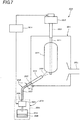
- a manufacturing equipment 10 for carrying out the method for manufacturing a glass-fine-particle-deposited body according to the present embodiment is one for depositing glass fine particles by the VAD method, a supporting rod 12 is suspended inside a reaction container 11 from the above, and a starting rod 13 is attached to the lower end of the supporting rod 12. An exhaust pipe 21 is attached to a side face of the reaction container 11.
- the supporting rod 12 is held at the upper end by a lifting and rotating device 15 and is lifted with rotation by the lifting and rotating device 15.
- the lifting rate of the lifting and rotating device 15 is controlled by a control device 16 so that the outer diameter of a glass-fine-particle-deposited body 14 becomes even.
- the glass-fine-particle-deposited body 14 is formed by depositing glass fine particles 20 on the starting rod 13. Also, the glass fine particles 20 in the reaction container 11, which are not adhered to the starting rod 13 and the glass-fine-particle-deposited body 14, are discharged through the exhaust pipe 21.
- a burner 18 for cladding that is a burner for producing glass-fine-particles is placed at a lower part of the inside of the reaction container 11 and a source material gas and a flame forming gas are supplied to the burner 18 for cladding by a gas supplying device.
- the burner 18 for cladding is, for example, a multiple pipe burner such as an eightfold pipe one.
- the gas supplying device for supplying the flame forming gas is omitted.
- SiCl 4 as a source material gas, H 2 and O 2 as flame forming gases, N 2 as a burner sealing gas, and the like are charged.
- the glass fine particles 20 are produced by a flame hydrolysis reaction, and the glass fine particles 20 are deposited on the starting rod 13 to prepare a glass-fine-particle-deposited body 14 having a predetermined outer diameter.
- the liquid source material 28 in the source material container 22 is controlled to a temperature of a boiling point (e.g., a standard boiling point is 57.6°C in the case of SiCl 4 ) or higher in the temperature controlled booth 24 and is vaporized in the source material container 22, and the supply amount of the source material gas to be supplied to the burner 18 for cladding is controlled by MFC 23.
- a temperature of a boiling point e.g., a standard boiling point is 57.6°C in the case of SiCl 4
- MFC 23 the supply amount of the source material gas to be supplied to the burner 18 for cladding
- the control of the supply amount of the source material gas by MFC 23 is conducted based on the command value from a control device 16.
- At least a part of the gas supplying pipe 25 from the source material container 22 to the burner 18 for cladding is temperature-controlled so that the temperature at the burner side becomes high and temperature gradient becomes 25°C/m or more.
- the material of the gas supplying pipe 25 may be a fluorocarbon resin (Teflon (registered trademark)) or the like but, in the case where it is held at a temperature of 200°C or higher, the material of the gas supplying pipe 25 is preferably a metallic one such as SUS, which is excellent in heat resistance.
- outer circumference of the gas supplying pipe 25 from the temperature controlled booth 24 to the burner 18 for cladding is wound with a tape heater 26 that is a heating element.
- the tape heater 26 is a flexible heater in which extrafine twisted wires of a metal heating element or a carbon-made fibrous planar heating element are covered with a protective material. When the tape heater 26 is energized, the gas supplying pipe 25 is heated.
- the first tape heater 26A is wound at the side of the burner 18 for cladding
- the second tape heater 26B is wound so as to be neighboring at the side
- the third tape heater 26C is wound at the temperature controlled booth 24 side.
- the length of the gas supplying pipe 25 between the temperature controlled booth 24 and the burner 18 for cladding is made 1 m.
- thermocouples are placed at both ends and middle of the outer circumference of the gas supplying pipe 25 and respective temperatures are regulated by the tape heaters 26A, 26B, and 26C.
- the temperature of the thermocouple placed at one end of the pipe is regulated at 120°C by the third tape heater 26C
- the temperature of the thermocouple placed at the middle of the pipe is regulated at 140°C by the second tape heater 26C
- the temperature of the thermocouple placed at one end of the pipe (burner 18 side) is regulated at 160°C by the third tape heater 26C
- the pipe is temperature-controlled at a temperature gradient of 40°C/m.
- the gas supplying pipe 25 from the temperature controlled booth 24 to the burner 18 for cladding is temperature-controlled so that the burner side has a high temperature and the temperature gradient becomes 25°C/m or more as mentioned above, the volume of the source material gas in the gas supplying pipe 25 is expanded as the gas advances from the temperature controlled booth 24 to the burner 18 for cladding and the flow rate of the source material gas is accelerated.
- the constitution with the aforementioned three kinds of tape heaters 26A, 26B, and 26C is one example for realizing the invention but the invention can be realized by another constitution.
- the tape heater 26B when a part of the tape heater 26B is controlled so as to be 140°C and the other tape heaters (26A, 26C) are controlled with the same electric power as the case of the tape heater 26B, an effect can be obtained.
- the length of the gas supplying pipe 25 between the temperature controlled booth 24 and the burner 18 for cladding is made 1 m but the length of the gas supplying pipe 25 can be appropriately adjusted.
- the inertial force of the glass fine particles 20 produced in the burner flame is increased and the straight advancing ability of the glass fine particles 20 is promoted, so that the glass fine particles 20 are prone to drop out of the gas flow in the flame and the adhering efficiency of the glass fine particles 20 on the starting rod 13 and the glass-fine-particle-deposited body 14 can be improved.
- the pipe diameter is designed so that the Reynolds number (Re number) of the source material gas flowing in the gas supplying pipe 25 becomes 2,000 or more, preferably 4,000 or more, further preferably 8,000 or more.
- the flow of the source material gas in the gas supplying pipe 25 becomes turbulent and the source material gas is efficiently heated in the gas supplying pipe 25, so that the temperature can be easily elevated.
- Fig. 4 shows the temperature of the source material gas flowing in the gas supplying pipe 25 in the case where the whole length of the gas supplying pipe 25 is heated at a constant temperature of 140°C. From Fig. 4 , it is understood that the source material gas flowing in the gas supplying pipe 25 is easily heated as the Re number increases.
- the supporting rod 12 is attached to the lifting and rotating device 15, and the starting rod 13 attached to the lower end of the supporting rod 12 is placed in the reaction container 11.
- the source material gas is chemically changed to the glass fine particles 20 by the flame hydrolysis reaction in an oxyhydrogen flame formed by the burner 18 for cladding and the glass fine particles 20 are deposited on the starting rod 13.
- the glass fine particles flowing along the flame gas flow have higher Stokes number as the flow rate increases, the inertial force of the glass fine particles is increased and the straight advancing ability of the glass fine particles is improved.
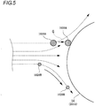
- the flame gas flow G bumps against the glass-fine-particle-deposited body 14 and the flowing direction is sharply changed to the outer circumferential direction of the glass-fine-particle-deposited body 14, the glass fine particles 20A having a large inertial force have a straight advancing ability, so that the particles bump against the glass-fine-particle-deposited body 14 as they flow.
- the glass fine particles 20B having a small inertial force flow along the flame gas flow G, the particles flow away in an outer circumferential direction of the glass-fine-particle-deposited body 14. Therefore, it is important how to increase the inertial force of the glass fine particles 20.
- the flow rate of the source material gas flowing in the gas supplying pipe 25 is accelerated toward the downstream side of the gas supplying pipe 25 to increase the inertial force of the glass fine particles 20 in the burner flame.
- the glass fine particles are prone to drop out of the flow of the flame gas and the adhering efficiency of the glass fine particles 20 on the starting rod 13 and the glass-fine-particle-deposited body 14 can be improved.
- the glass base material is manufactured using the following materials.
- Deposition of glass fine particles is performed by the VAD method. After the resulting glass-fine-particle-deposited body is heated to 1,100°C in a mixed atmosphere of an inert gas and chlorine gas, it is heated to 1,550°C in an He atmosphere to impart transparency.
- the temperature of outer circumference of the gas supplying pipe was measured at three points along a longitudinal direction of the pipe, and the minimum temperature gradient: T (°C/m) between the measuring points and the source material yield of the glass fine particles: X (%) are evaluated.
- the source material yield of the glass fine particles X is taken as a mass ratio of the glass fine particles actually deposited on the starting rod and the glass-fine-particle-deposited body to the SiO 2 mass in the case where 100% of the SiCl 4 gas to be charged is chemically reacted into SiO 2 .
- the gas supplying pipe from the temperature controlled booth to the burner for cladding is heated by a heating element such that the burner side has a higher temperature and the minimum temperature gradient is stepwise controlled from 5°C/m to 40°C/m, and the source material yield in each temperature gradient is calculated.
- temperature gradient is not controlled and the source material yield in the case where the minimum temperature gradient T is less than 5°C/m is calculated.
- the source material yield X is 32% or more.
- the temperature of the source material gas immediately before charging into the burner is 270°C, namely the temperature of the source material gas is 212.4°C higher than the standard boiling point of SiCl 4 that is the source material gas and, at the time, the source material yield X is improved to 40%.
- the gas supplying pipe 25 from the temperature controlled booth 24 to the burner 18 for cladding is controlled to a temperature of 100°C or higher by the tape heater 26 that is a heating element and also the Reynolds number Re of the source material gas flowing in the gas supplying pipe 25 from the source material container 22 to the burner 18 for cladding is controlled to 2,000 or more.
- the gas flow flowing in the pipe is a laminar flow in the case where the Reynolds number is less than 2,000, is in a transient region between 2,000 and 4,000, and becomes a turbulent flow in the case where the number is 4,000 or more.
- it is sufficient that at least a part of the gas supplying pipe 25 is controlled to 100°C or higher but the whole pipe may be controlled to 100°C or higher.
- the coefficient of kinematic viscosity v of SiCl 4 at the temperature of 100°C is about 3.1 ⁇ 10 -6 (m 2 /s).
- the Reynolds number Re is controlled to preferably 4,000 or more, further preferably 8,000 or more.
- the source material gas is sufficiently heated by the tape heater 26 in the gas supplying pipe 25 and the temperature is elevated. Thereby, the flame hydrolysis reaction of the source material gas to be spouted from the burner is promoted in the burner flame.
- the number of the glass fine particles formed in the flame is increased. Moreover, since the growth of the glass fine particles is advanced, the outer diameter of the glass fine particles also is increased. Furthermore, when the outer diameter is increased, the aggregation (combination between particles) by turbulent diffusion is promoted. Owing to these effects, the inertial force of the glass fine particles in the burner flame is increased, so that the glass fine particles are prone to drop out of the flow of the flame gas and the adhering efficiency of the glass fine particles 20 on the starting rod 13 and the glass-fine-particle-deposited body 14 can be improved.
- the glass fine particles 20 are deposited on the starting rod 13 shown in Fig. 1 and, thereafter, they are heated in a mixed atmosphere of an inert gas and chlorine gas and heated in an He atmosphere to impart transparency.
- the pipe inner diameter D is designed so that the desired Reynolds number Re is obtained.
- the tape heater 26 wound on the outer circumference of the gas supplying pipe 25 at least a part of the gas supplying pipe 25 is controlled to a temperature of 100°C or higher. Thereby, the average flow rate of the source material gas flowing in the pipe is controlled so as to obtain the desired Reynolds number Re.
- the Reynolds number Re of the source material gas flowing in the pipe can be controlled by changing the pipe inner diameter D of the gas supplying pipe 25 or the temperature of the gas supplying pipe 25. Moreover, when the temperature of the source material gas flowing in the gas supplying pipe 25 is changed, the coefficient of kinematic viscosity of the source material gas is also varied.
- the glass-fine-particle-deposited body 14 obtained by deposition of the glass fine particles 20 on the starting rod 13 is lifted up in accordance with the growth rate of the lower end part of the glass-fine-particle-deposited body 14 by means of the lifting and rotating device 15.
- At least a part of the gas supplying pipe 25 from the temperature controlled booth 24 to the burner 18 for cladding is controlled to a temperature of 100°C or higher by the tape heater 26 that is a heating element and also the Reynolds number of the glass source material gas flowing in the gas supplying pipe 25 from the source material container 22 to the burner 18 for cladding is controlled to 2,000 or more, preferably 4,000 or more, further preferably 8,000 or more.
- the flow of the source material gas in the gas supplying pipe 25 becomes turbulent, the source material gas is sufficiently heated by the tape heater 26 in the gas supplying pipe 25, and the temperature is elevated. As a result, the flame hydrolysis reaction of the source material gas to be spouted from the burner is promoted in the burner flame.
- the number of the glass fine particles formed in the flame is increased. Moreover, since the growth of the glass fine particles is advanced, the outer diameter of the glass fine particles is also increased. Furthermore, when the outer diameter is increased, the aggregation (combination between particles) by turbulent diffusion is promoted. Owing to these effects, the inertial force of the glass fine particles in the burner flame is increased, so that the glass fine particles are prone to drop out of the flow of the flame gas and the adhering efficiency of the glass fine particles 20 on the starting rod 13 and the glass-fine-particle-deposited body 14 can be improved.
- the temperature of the source material gas flowing in the gas supplying pipe 25 is elevated, the volume of the source material gas is expanded and the flow rate of the glass fine particles 20 produced in the burner flame is also increased.
- the inertial force of the glass fine particles 20 flowing along the flame gas flow is determined by the Stokes number. Since the Stokes number is proportional to the flow rate of particles, the temperature of the source material gas in the gas supplying pipe 25 is elevated and, when the flow rate of the glass fine particles 20 is increased, the inertial force of the glass fine particles 20 is increased. Owing to these effects, the adhering efficiency of the glass fine particles 20 on the starting rod 13 and the glass-fine-particle-deposited body 14 can be improved.
- Example 2 one Example of the methods for manufacturing a glass-fine-particle-deposited body and a glass base material of the invention is described.
- the glass-fine-particle-deposited body is manufactured using the following materials.
- Deposition of glass fine particles is performed by the VAD method. After the resulting glass-fine-particle-deposited body is heated to 1,100°C in a mixed atmosphere of an inert gas and chlorine gas, it is heated to 1,550°C in an He atmosphere to impart transparency.
- the pipe inner diameter D and the pipe temperature of the gas supplying pipe are appropriately selected, the Reynolds number Re is changed, and the Reynolds number Re of the source material gas flowing in the pipe when the flow of the source material gas becomes 3 SLM and the source material yield X (%) of the glass fine particles are evaluated.
- the source material yield X is taken as a mass ratio of the glass fine particles actually deposited on the starting rod and the glass-fine-particle-deposited body to the SiO 2 mass in the case where 100% of the SiCl 4 gas to be charged is chemically reacted into SiO 2 .
- Examples B1-B5 are Reference Examples falling outside of the scope of the claims.
- Example B-4 is an example in which the temperature of the gas supplying pipe is 150°C, namely the temperature of the gas supplying pipe is 92.4°C higher than the standard boiling point of SiCl 4 that is the source material gas, where the Re number becomes 10,408 and the source material yield X is improved to 32%.
- Example B-5 is an example in which the temperature of the gas supplying pipe is 260°C, namely the temperature of the gas supplying pipe is 202.4°C higher than the standard boiling point of SiCl 4 that is the source material gas, where the Re number becomes 11,546 and the source material yield X is increased to 35%.
- Example B-6 is an example falling within the scope of the claims in which the temperature gradient of the gas supplying pipe is a slope of 50°C/m with temperature elevation from the source material container toward the burner and the temperature of the gas supplying pipe in the vicinity of the burner is 270°C, namely the temperature of the gas supplying pipe is 212.4°C higher than the standard boiling point of SiCl 4 that is the source material gas.
- the Re number becomes 11,554 and the turbulent diffusion of the glass fine particles in the flame is promoted owing to the temperature gradient in a longitudinal direction of the gas supplying pipe, so that the source material yield X is jumped to 37%.
- Fig. 4 shows the temperature of the source material gas flowing in the gas supplying pipe in the case where the whole length of the gas supplying pipe is heated to a constant value of 140°C. From the figure, it is understood that the temperature is slowly elevated along the longitudinal direction of the pipe in a laminar flow state at which the Reynolds number Re is 1,870 (broken line in the figure) but the temperature is sharply elevated at an upstream side of the pipe in a turbulent flow state at which the Reynolds number Re is 2,000 (dashed line in the figure) or 4,000 (two-dot chain line in the figure).
- the temperature of the source material gas to be charged into the burner is equal to the temperature of the gas supplying pipe in Examples B-1 to B-5 and the temperature of the source material gas to be charged into the burner is equal to the temperature of the gas supplying pipe in the vicinity of the burner in Example B-6.
- the pipe diameter is designed so that the Reynolds number Re (Re number) of the source material gas flowing in the gas supplying pipe 25 becomes 2,000 or more, preferably 4,000 or more, further preferably 8,000 or more.
- Re number the Reynolds number of the source material gas flowing in the gas supplying pipe 25 becomes 2,000 or more, preferably 4,000 or more, further preferably 8,000 or more.
- the temperature distribution in a longitudinal direction of the gas supplying pipe 25 is further preferably controlled so that the temperature increases from the source material container 22 side to the side of the burner 18 for cladding. Specifically, by controlling the temperature gradient of the gas supplying pipe 25 to 25°C/m or more, it becomes possible to enhance the adhering efficiency of the glass fine particles.
- the glass fine particles 20 are deposited on the starting rod 13 shown in Fig. 1 and, thereafter, they are heated in a mixed atmosphere of an inert gas and chlorine gas and heated in an He atmosphere to impart transparency.
- the particle diameter of the glass fine particles is controlled to 10 (nm) or more, preferably 50 (nm), and the glass fine particles are aggregated among the particles in the flame of the burner for producing glass fine particles to make the mass of the aggregated particle group 1.8 ⁇ 10 -17 (g) or more, preferably 2.8 ⁇ 10 -14 (g) or more.
- the aggregation rate by the turbulent diffusion depends on particle number concentration and is promoted by increasing the particle number concentration.
- the particle number concentration can be increased by changing 75% or more of the SiCl 4 gas into SiO 2 gas within 700 mm, preferably within 500 mm, further preferably within 300 mm from the tip of the burner.
- the inertial mass of the particle group is increased.
- the particle group having an increased inertial mass is prone to drop out of the gas flow in the flame.
- the particle group of the glass fine particles is prone to adhere to the starting rod and the glass-fine-particle-deposited body as targets and thus the source material yield can be improved.
- a source material gas such as SiCl 4
- the glass fine particle group 1020B having a small inertial force follows the flow direction of the flame gas flow G.
- the glass fine particle group 1020A having a large inertial force does not follow the flow direction of the flame gas flow G owing to the improved straight advancing ability and is prone to drop out of the flame gas flow G (see Fig. 5 ). Therefore, it becomes important how to increase the inertial force of the glass fine particle group.
- the particle diameter of the glass fine particles is controlled to 10 (nm) or more, and the glass fine particles are aggregated among the particles to make the mass of the aggregated particle group 1.8 ⁇ 10 -17 (g) or more.
- the aggregation is promoted by the turbulent diffusion, the aggregated particle group is prone to drop out of the flame gas flow, and thus the adhering efficiency of the glass fine particles on the starting rod and the glass-fine-particle-deposited body can be improved.
- the glass base material is manufactured using the following materials.
- glass fine particles are deposited by the above-described VAD method to manufacture a glass-fine-particle-deposited body.
- the glass source material yield A (%) of the glass fine particles is evaluated with fluctuating the temperature T of the source material gas to be charged into the burner, the particle diameter D (nm) of the glass fine particles, and the mass M (g) of the particle group.
- the particle diameter D of the glass fine particles can be changed by adjusting the temperature T of the source material gas to be charged into the burner and the flow of the flame forming gas. Moreover, as mentioned above, by chemically changing the source material gas (SiCl 4 ) into SiO 2 gas at a region near to the source material gas-spouting port of the burner for producing glass fine particles (e.g., a region 20 to 700 mm apart from the source material gas-spouting port), the production and growth of the SiO 2 glass fine particles can be promoted.
- the particle diameter D is taken as minimum particle diameter confirmed on an electron microscope (SEM) and the temperature of the source material gas means the temperature of the source material gas immediately before charging into the burner.
- the glass source material yield A of the glass fine particles is taken as a mass ratio of the glass fine particles actually deposited on the starting rod and the glass-fine-particle-deposited body to the SiO 2 mass in the case where 100% of the SiCl 4 gas to be charged is chemically reacted into SiO 2 .
- Example C-5 in which the temperature T of the source material gas is 260°C, namely the temperature of the source material gas is 202.4°C higher than the standard boiling point of SiCl 4 that is the source material gas, the particle diameter of the glass fine particles is 77 nm or more, and the mass M of the particle group is 2.06 ⁇ 10 -13 (g), the glass source material yield A becomes 56.2%.
- Example C-6 is an example in which the temperature gradient of the gas supplying pipe is a slope of 20°C/m with temperature elevation from the source material container to the burner and the temperature of the source material gas to be charged into the burner is elevated to 170°C.
- Example C-5 Although the particle diameter D is smaller than in Example C-5, the turbulent diffusion of the glass fine particles in the flame is promoted owing to the effect of the temperature gradient in a longitudinal direction of the gas supplying pipe, so that the mass M of the particle group becomes larger than in Example C-5 and the glass source material yield A is jumped to 58.6%.
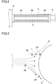
- the burner 18 for cladding is, for example, a multiple pipe burner such as eightfold pipe one and, as shown in Fig. 6B , is preferably a multiple pipe burner having a protrusion structure.
- the multiple pipe burner having a protrusion structure can form an inside flame at the burner central axis side and can form an outside flame at the more outer circumference of the inside flame.
- the outside multiple pipes which form the outside flame is formed so that the length of the outside multiple pipes is longer toward the side of the source material gas-spouting port than the length of the inside multiple pipes which form the inside flame.
- Figs. 6A and 6B are longitudinal cross-sectional views showing only a part of the burner tip side, and only one side toward the central axis of the burner is shown in the figures.
- the temperature of the source material gas (SiCl 4 ) to be charged into the burner 18 for cladding is kept at 100°C or higher and the source material gas is chemically changed to silicon oxide gas within 700 mm from the source material gas-spouting port of the burner 18 for cladding.
- the partial pressure of the chemically changed silicon oxide gas is controlled to the saturated vapor pressure of the silicon oxide gas or higher at the position of 20 mm from the glass source material gas-spouting port of the burner 18 for cladding.
- the reaction of the silicon oxide gas to the silicon oxide particles can be efficiently advanced. Namely, since the source material gas is not diffused to a diameter direction at a position near to the burner 18 for cladding, when the glass source material gas is chemically changed to the silicon oxide gas at a position near to the glass source material gas-spouting port of the burner 18 for cladding, the partial pressure of the silicon oxide gas increases and the change from the silicon oxide gas to silicon oxide particles that are solid becomes easy. Simultaneously, since the growth of the silicon oxide particles is promoted, the silicon oxide particles tend to have a large diameter.
- the partial pressure of the silicon oxide gas formed at a position apart from the burner 18 for cladding is difficult to increase. Accordingly, even when the silicon oxide gas is formed at a position apart from the burner 18 for cladding, the partial pressure of the silicon oxide gas is low, so that it is difficult to change the silicon oxide gas into the silicon oxide particles and also the particle diameter difficultly grows.
- the temperature of the glass source material gas to be introduced into the burner 18 for cladding is preferably kept at 150°C or higher and the source material gas is preferably chemically changed into the silicon oxide gas within 670 mm from the source material gas-spouting port of the burner 18 for cladding.
- the temperature of the glass source material gas is preferably kept at 200°C or higher and the source material gas is preferably chemically changed into the silicon oxide gas within 650 mm from the source material gas-spouting port of the burner 18 for cladding.
- the temperature of the glass source material gas is further preferably kept at 300°C or higher and the source material gas is preferably chemically changed into the silicon oxide gas within 620 mm from the source material gas-spouting port of the burner 18 for cladding.
- the partial pressure of the chemically changed silicon oxide gas is preferably controlled to preferably 1.5 times or more, further preferably 2 times or more the saturated vapor pressure of the silicon oxide gas at the position of 20 mm from the source material gas-spouting port of the burner 18 for cladding.
- the chemical reaction of the source material gas to the silicon oxide gas also difficultly occurs.
- the position at which the source material gas is changed into the silicon oxide gas and the partial pressure of the silicon oxide gas produced in the flame of the burner 18 for cladding can be controlled also by the flow of the flame forming gases (H 2 , O 2 ) in addition to the temperature of the source material gas to be charged into the burner 18 for cladding.
- the burner 18 for cladding is made to have a multiple flame structure to thereby form a protrusion structure in which the inside flame near to the source material gas-spouting port is surrounded with multiple circular pipes, the partial pressure of the silicon oxide gas produced in the flame can be increased.
- the number of the glass fine particles 20 produced by the burner 18 for cladding can be increased and the growth of the particle diameter can be promoted.
- the particle diameter grows, the inertial force of the glass fine particles 20 increases and the glass fine particles 20 are prone to drop out of the gas flow without following the flame gas flow. Thereby, the glass fine particles 20 are prone to adhere to the starting rod 13 and the glass-fine-particle-deposited body 14 and thus the adhering efficiency can be improved.
- the glass fine particles 20 are deposited on the starting rod 13 shown in Fig. 1 and, thereafter, they are heated in a mixed atmosphere of an inert gas and chlorine gas and heated in an He atmosphere to impart transparency.
- the deposition step in the present embodiment by energizing the tape heater 26 wound on the outer circumference of the gas supplying pipe 25 that supplies the source material gas to the burner 18 for cladding, at least a part of the gas supplying pipe 25 is temperature-controlled to an appropriate temperature of 100°C or higher and the temperature of the source material gas to be charged into the burner 18 for cladding is kept at preferably 100°C or higher, preferably 150°C or higher, more preferably 200°C or higher, further preferably 300°C or higher.
- the source material gas is chemically changed into the silicon oxide gas within 700 mm, preferably within 670 mm, more preferably within 650 mm, further preferably within 620 mm from the source material gas-spouting port of the burner 18 for cladding.
- the partial pressure of the chemically changed silicon oxide gas is controlled to the saturated vapor pressure of the silicon oxide gas or more, preferably 1.5 times or more, more preferably 2 times or more, further preferably 10 times or more the saturated vapor pressure of the silicon oxide gas in the vicinity of 20 mm from the source material gas-spouting port of the burner 18 for cladding.
- the temperature of the source material gas to be charged into the burner 18 for cladding is kept at 100°C or higher, and the source material gas is chemically changed into the silicon oxide gas within 700 mm from the source material gas-spouting port of the burner 18 for cladding.
- the partial pressure of the chemically changed silicon oxide gas is controlled to the saturated vapor pressure of the silicon oxide gas or more at the position of 20 mm from the source material gas-spouting port of the burner 18 for cladding.
- the change of the silicon oxide gas to the silicon oxide particles that are solid is prone to occur in the flame of the burner 18 for cladding.
- the particle diameter becomes large.
- the inertial force of the glass fine particles 20 is increased and the glass fine particles 20 are prone to drop out of the flame gas flow. Therefore, the glass fine particles 20 are prone to adhere to the starting rod 13 and the glass-fine-particle-deposited body 14 and thus the adhering efficiency can be improved.
- the glass base material is manufactured using the following materials.
- Deposition of glass fine particles is performed by the VAD method. After the resulting glass-fine-particle-deposited body is heated to 1,100°C in a mixed atmosphere of an inert gas and chlorine gas, it is heated to 1,550°C in an He atmosphere to impart transparency.
- the temperature T (°C) of the source material gas to be charged into the burner, the distance X (mm) from the source material gas-spouting port of the burner to the position at which 100% of the source material gas is chemically changed into the silicon oxide gas, and the pressure ratio Y of the partial pressure of the silicon oxide gas at the position of 20 mm from the source material gas-spouting port of the burner/the saturated vapor pressure of the silicon oxide gas are fluctuated, and the source material yield A (%) is evaluated.
- the source material yield A is taken as a mass ratio of the glass fine particles actually deposited on the starting rod and the glass-fine-particle-deposited body to the SiO 2 mass in the case where 100% of the SiCl 4 gas to be charged is chemically reacted into SiO 2 .
- a usual multiple pipe burner as shown in Fig. 6A is taken as "1” and a multiple pipe burner having a protrusion structure as shown in Fig. 6B is taken as "2". Results are shown in Table 4. Examples D1-D6 are Reference Examples falling outside the scope of the claims.
- Example D-5 in which the temperature T of the source material gas is 350°C, namely the temperature of the source material gas is controlled to 292.4°C higher than the standard boiling point of SiCl 4 that is the source material gas, and the reaction distance X is 600 mm, it is understood that the pressure ratio Y is so high as 1.5 and the source material yield A is also so high as 64.4%.
- Example D-6 in which the multiple pipe burner having a protrusion structure is used, even when the temperature T of the source material gas is 50°C lower than in Example D-5, a high source material yield A the same as in Example D-5 can be obtained.
- Example D-8 is an example falling within the scope of the claims in which the temperature gradient of the gas supplying pipe is a slope of 63°C/m with temperature elevation from the source material container to the burner and the temperature T of the source material gas is controlled to 350°C.
- the reaction distance X is shortened to 570 mm, the pressure ratio Y is increased to 2, and the source material yield A is improved to 73%.
- At least a part of the gas supplying pipe 25 from the temperature controlled booth 24 to the burner 18 for cladding is controlled to a temperature of 100°C or higher by the tape heater 26 that is a heating element and also the Stokes number S of the glass fine particles 20 produced by the burner 18 for cladding is controlled to 0.5 or more.
- the Stokes number S of the glass fine particles 20 in a flame gas is represented by the following equation when the particle density is taken as ⁇ , the particle diameter is taken as d, the particle velocity is taken as u, the coefficient of viscosity of the flame gas is taken as ⁇ , and the diameter of the glass-fine-particle-deposited body is taken as L.
- S ⁇ d 2 u / 18 ⁇ L
- the above Stokes number S is controlled to preferably 1.0 or more, further preferably 1.5 or more.
- the inertial force of the glass fine particles 20 produced by the burner 18 for cladding can be further increased.
- the glass fine particles 20 When the inertial force of the glass fine particles 20 is increased, the straight advancing ability of the glass fine particles 20 is promoted, so that they do not follow the flame gas flow and are prone to drop out of the flame gas flow. Thereby, the glass fine particles 20 are prone to adhere to the starting rod 13 and the glass-fine-particle-deposited body 14 and thus the adhering efficiency can be improved.
- the source material gas is heated in the gas supplying pipe 25 and the particle velocity u of the glass fine particles 20 spouted from the burner 18 for cladding is increased.
- the flame hydrolysis reaction of the source material gas proceeds at a flame upstream side where the flame is not spread by controlling, so that the partial pressure of the SiO 2 gas can be increased at the flame upstream side.
- the number of the glass fine particles 20 produced in the burner flame is increased and simultaneously, since the growth of the glass fine particles 20 is advanced, the outer diameter of the glass fine particles 20 is also increased.
- the source material gas to be charged into the burner 18 for cladding to a high temperature the particle velocity u of the glass fine particles 20 is increased and also it becomes possible to make the particle diameter d large, so that the Stokes number S can be increased.
- the glass fine particles 20 are deposited on the starting rod 13 shown in Fig. 1 and, thereafter, they are heated in a mixed atmosphere of an inert gas and chlorine gas and heated in an He atmosphere to impart transparency.
- the deposition step in the present embodiment by energizing the tape heater 26 wound on the outer circumference of the gas supplying pipe 25 that supplies the source material gas to the burner 18 for cladding, at least a part of the gas supplying pipe 25 is temperature-controlled to an appropriate temperature of 100°C or higher.
- the gas supplying pipe 25 from the temperature controlled booth 24 to the burner 18 for cladding is controlled to a temperature of 100°C or higher by the tape heater 26 that is a heating element and also the source material gas flowing in the gas supplying pipe 25 is heated by the tape heater 26 so that the Stokes number S of the glass fine particles 20 produced by the burner 18 for cladding becomes 0.5 or more, preferably 1.0 or more, further preferably 1.5 or more.
- the glass fine particles 20 spouting from the burner 18 for cladding have an increased inertial force and thus are prone to drop out of the gas flow of the burner flame. Therefore, the adhering efficiency of the glass fine particles 20 on the starting rod 13 and the glass-fine-particle-deposited body 14 can be improved.
- the glass base material is manufactured using the following materials.
- Deposition of glass fine particles is performed by the VAD method. After the resulting glass-fine-particle-deposited body is heated to 1,100°C in a mixed atmosphere of an inert gas and chlorine gas, it is heated to 1,550°C in an He atmosphere to impart transparency.
- the particle velocity u of the glass fine particles 20 produced in the burner flame can be increased and also, since the reaction of the source material is promoted, the particle diameter d of the glass fine particles can be made large.
- the Stokes number S can be changed.
- the source material yield X (%) at the time is evaluated with fluctuating the average particle diameter and the Stokes number.
- the source material yield X is taken as a mass ratio of the glass fine particles actually deposited on the starting rod and the glass-fine-particle-deposited body to the SiO 2 mass in the case where 100% of the SiCl 4 gas to be charged is chemically reacted into SiO 2 .
- the average particle diameter is calculated from the surface area value of the particles measured by the BET surface area measurement method. Results are shown in Table 5.
- the gas supplying pipe temperature is an outer circumference temperature of the gas supplying pipe in the vicinity of the burner and the temperature is equal to the temperature of the source material gas to be charged into the burner.
- Examples E1-E7 are Reference Examples falling outside the scope of the claims.
- the source material yield X becomes 58%.
- Example E-8 is an example falling within the scope of the claims in which the temperature of the gas supplying pipe is elevated at a slope of 44°C/m from the source material container toward the burner and, owing to the effect of imparting the temperature gradient in a longitudinal direction of the gas supplying pipe, the flow rate of the glass fine particles produced in the flame is further increased and the source material yield X is raised to 64%.
- Example E-10 is an example falling within the scope of the claims in which the temperature of the gas supplying pipe is elevated at a slope of 65°C/m from the source material container toward the burner and the gas supplying pipe temperature is controlled to 300°C, namely the gas supplying pipe temperature is controlled to 242.4°C higher than the standard boiling point of SiCl 4 that is the source material gas, where the Stokes number S becomes 2.84 and the source material yield X is jumped to 70%.
- the source material yield X becomes 29% or more and the source material yield X increases as the particle diameter increases.
- the source material yield X increases as the Stokes number S increases but the source material yield X tends to be saturated when the Stokes number exceeds 100.
- Comparative Examples E-1 to E-3 in which the gas supplying pipe temperature is lower than 100°C and the Stokes number S is less than 0.5, the source material yield X of the glass fine particles is so low as 25% or less.
- the source material yield X of the glass fine particles is so low as 25% or less.
- a manufacturing equipment 2010 for carrying out the method for manufacturing a glass-fine-particle-deposited body according to the present embodiment is one for depositing glass fine particles by the VAD method, a supporting rod 2012 is suspended inside a reaction container 2011 from the above, and a starting rod 2013 is attached to the lower end of the supporting rod 2012.
- the supporting rod 2012 is held by a lifting and rotating device 2015 and the lifting rate is controlled by a control device 2016.
- a burner 2018 for cladding that is a burner for producing glass fine particles is placed at a lower part of the reaction container 2011 and spouts the glass fine particles 2020 toward the starting rod 2013 to form a glass-fine-particle-deposited body 2014. Also, the glass fine particles 2020 in the reaction container 2011, which are not adhered to the starting rod 2013 and the glass-fine-particle-deposited body 2014, are discharged through an exhaust pipe 2021.
- a source material gas and a flame forming gas are supplied to the burner 2018 for cladding by a gas supplying device 2019.
- the gas supplying device 2019 comprises a source material container 2022 for storing a liquid source material 2028, MFC 2023 for controlling a supply flow rate of the source material gas, a gas supplying pipe 2025 for introducing the source material gas into the burner 2018 for cladding, and a temperature controlled booth 2024 for keeping the source material container 2022, MFC 2023, and a part of the gas supplying pipe 2025 at a predetermined temperature or higher.
- At least a part of the gas supplying pipe 2025 from the temperature controlled booth 2024 to the burner 2018 for cladding is controlled to a temperature of 100°C or higher by a tape heater 2026 that is a heating element and also the region A of one third or less of the longitudinal direction from the end part at the gas supplying pipe 2025 side in the burner 2018 for cladding is controlled to a temperature of 100°C or higher by a heating element.
- a heating element for example, a tape heater is used.
- At least a part including a connecting portion with the burner 2018 for cladding in the gas supplying pipe 2025 is controlled so as to be 100°C or higher but the whole pipe may be controlled to be 100°C or higher.
- the temperature of the source material gas spouted from the source material container 2022 into the burner flame through the burner 2018 for cladding is elevated and the flame hydrolysis reaction of the source material gas in the burner flame can be promoted.
- the number of the glass fine particles produced in the flame is increased. Moreover, since the growth of the glass fine particles 20 is advanced, the outer diameter of the glass fine particles is also increased. Furthermore, the increase in the particle diameter promotes the aggregation (combination between particles) by turbulent diffusion. Owing to these effects, the inertial force of the glass fine particles in the burner flame is increased and the glass fine particles are prone to drop out of the flow of the flame gas, so that the adhering efficiency of the glass fine particles 2020 on the starting rod 2013 and the glass-fine-particle-deposited body 2014 can be improved.
- the material of the gas supplying pipe 2025 in the case where the gas supplying pipe 2025 is held at a temperature lower than 200°C, the material of the gas supplying pipe 2025 may be a fluorocarbon resin (Teflon (registered trademark)) or the like but, in the case where it is held at a temperature of 200°C or higher, the material of the gas supplying pipe 2025 is preferably a metallic one such as SUS, which is excellent in heat resistance.
- the outer circumference of the gas supplying pipe 2025 from the temperature controlled booth 2024 to the burner 2018 for cladding and the region A of one third or less of the longitudinal direction from the end part at the gas supplying pipe 2025 side in the burner 2018 for cladding is wound with a tape heater 2026 that is a heating element.
- the tape heater 2026 is a flexible heater in which extrafine twisted wires of a metal heating element or a carbon-made fibrous planar heating element are covered with a protective material. When the tape heater 2026 is energized, the gas supplying pipe 2025 and the burner 2018 for cladding are heated.
- the inner diameter of the gas supplying pipe 2025 is designed so that the Reynolds number (Re number) of the source material gas flowing in the gas supplying pipe 2025 and the burner 2018 for cladding becomes 2,000 or more, preferably 4,000 or more, further preferably 8,000 or more. Thereby, the flow of the source material gas in the gas supplying pipe 2025 becomes turbulent and the source material gas is efficiently heated in the gas supplying pipe 2025, so that the temperature can be easily elevated.
- Re number Reynolds number
- the temperature distribution in a longitudinal direction of the gas supplying pipe 2025 and the burner 2018 for cladding is preferably controlled so that the temperature elevates from the source material container 2022 toward the burner 2018 for cladding.
- the temperature gradient of the gas supplying pipe 2025 to 25°C/m or more, it becomes possible to enhance the adhering efficiency of the glass fine particles 2020.
- the supporting rod 2012 is attached to the lifting and rotating device 2015, and the starting rod 13 attached to the lower end of the supporting rod 12 is placed in the reaction container 2011. Then, while the starting rod 2013 is rotated by the lifting and rotating device 2015, the source material gas is chemically changed to the glass fine particles 2020 by the flame hydrolysis reaction in an oxyhydrogen flame formed by the burner 2018 for cladding and the glass fine particles 2020 are deposited on the starting rod 2013.
- the gas supplying pipe 2025 and the region A of one third or less of the longitudinal direction from the end part at the gas supplying pipe 2025 side in the burner 2018 for cladding are controlled so as to be a temperature of 150°C or higher, preferably 260°C or higher, further preferably 300°C or higher.
- the adhering efficiency of the glass fine particles 2020 produced in the flame of the burner 2018 for cladding on the starting rod 2013 and the glass-fine-particle-deposited body 2014 can be improved.
- the glass-fine-particle-deposited body 2014 obtained by deposition of the glass fine particles 2020 on the starting rod 2013 is lifted up in accordance with the growth rate of the lower end part of the glass-fine-particle-deposited body 2014 by means of the lifting and rotating device 2015.
- the tape heater 2026 that is a heating element so as to be a temperature of 100°C or higher.
- the heating range of the burner 2018 for cladding it is sufficient to heat the range of one third or less of the longitudinal direction from the end part at the gas supplying pipe 2025 side. Even when a range wider than one third is heated, there is no effect of further elevating the temperature of the source material gas flowing in the burner. This is because the temperature is sufficiently elevated at the range other than one third from the end part at the gas supplying pipe 2025 side of the burner 2018 for cladding owing to radiant heat from the flame formed in the burner.
- the inertial force of the glass fine particles 2020 is determined by the Stokes number. Since the Stokes number is proportional to the flow rate of particles, the temperature of the source material gas in the burner 2018 for cladding is elevated and, when the flow rate of the glass fine particles 2020 is increased, the inertial force of the glass fine particles 2020 is increased. Owing to these effects, the adhering efficiency of the glass fine particles 2020 on the starting rod 2013 and the glass-fine-particle-deposited body 2014 can be improved.
- Deposition of glass fine particles is performed by the VAD method. After the resulting glass-fine-particle-deposited body is heated to 1,100°C in a mixed atmosphere of an inert gas and chlorine gas, it is heated to 1,550°C in an He atmosphere to impart transparency.
- the pipe temperature A (°C) and the burner temperature B (°C) are appropriately selected and the source material yield X (%) is evaluated.
- the source material yield X is taken as a mass ratio of the glass fine particles actually deposited on the starting rod and the glass-fine-particle-deposited body to the SiO 2 mass in the case where 100% of the SiCl 4 gas to be charged is chemically reacted into SiO 2 .
- the pipe temperature A is taken as an outer circumference temperature of the gas supplying pipe in the vicinity of the burner and the burner temperature B is taken as an outer circumference temperature at the position of one third of the longitudinal direction from the end part at the gas supplying pipe 2025 side in the burner for cladding.
- Example F-1 to F-5 the region until one third of the longitudinal direction from the end part at the gas supplying pipe 2025 side in the burner for cladding is heated and, in Example F-6, the region until one eighth of the longitudinal direction from the end part at the gas supplying pipe 2025 side in the burner for cladding is heated.
- Example F-1 to F-6 in which the pipe temperature A and the burner temperature B are controlled to 100°C or higher, the source material yield X becomes 55% or more, so that the source material yield X increases as the pipe temperature A and the burner temperature B are elevated.
- Example F-4 in which the pipe temperature A and the burner temperature B are 300°C, namely the pipe temperature A and the burner temperature B are 242.2°C higher than the standard boiling point of SiCl 4 that is the source material gas, the source material yield X becomes 67%.
- Example F-5 is an example falling within the scope of the claims in which the temperature gradient in a longitudinal direction of the gas supplying pipe and the burner for cladding is a slope of 70°C/m with temperature elevation from the source material container side toward the side of the burner for cladding and the burner temperature is 330°C, namely the burner temperature is 272.4°C higher than the standard boiling point of SiCl 4 that is the source material gas. Owing to the effect of imparting the temperature gradient in a longitudinal direction of the gas supplying pipe and the burner for cladding, the turbulent diffusion of the glass fine particles in the flame is promoted and the source material yield X is jumped to 69%.
- Example F-6 the pipe temperature is 300°C, the heating range of the burner is controlled to one eighth, and the outer circumference temperature at the position of one third of the longitudinal direction from the end part at the gas supplying pipe 2025 side in the burner is controlled to 290°C.
- Example F-4 it is understood that the source material yield X is slightly decreased but almost the same source material yield is obtained by narrowing the heating rage of the burner from one third to one eighth.
- Fig. 8 is a graph showing temperature change of the source material gas at a part of the longitudinal direction at the inside of the gas supplying pipe and the burner for producing glass fine particles.
- the data shown by a broken line indicates the case where the whole length of the gas supplying pipe is heated to 200°C but the burner is not heated. In this case, it is understood that the temperature of the source material gas is lowered in the burner.
- the data shown by a solid line indicates the case where the whole length of the gas supplying pipe and the region of one third of the longitudinal direction from the end part at the gas supplying pipe side in the burner are heated to 200°C. In this case, it is understood that the temperature of the source material gas flowing in the burner is not lowered.
- the methods for manufacturing a glass-fine-particle-deposited body and a glass base material of the invention are not limited to the aforementioned embodiments, and modification, improvement, and the like may be appropriately made at will.
- the case where the glass-fine-particle-deposited body is manufactured by the VAD method in the deposition step is described as one example but the manufacturing methods are effective for all the methods for manufacturing a glass-fine-particle-deposited body and a glass base material utilizing a flame decomposition reaction such as the OVD method or the MMD method.
- SiCl 4 is used as the source material gas but the case of core glass synthesis using SiCl 4 and GeCl 4 also exhibits an effect of improving the source material yield. Furthermore, a certain source material gas other than SiCl 4 (e.g., siloxane or the like) also affords the same effect.
- each constitutional element in the aforementioned embodiments is arbitrary and are not limited so long as they can accomplish the invention.
Landscapes
- Chemical & Material Sciences (AREA)
- Engineering & Computer Science (AREA)
- Chemical Kinetics & Catalysis (AREA)
- General Chemical & Material Sciences (AREA)
- Life Sciences & Earth Sciences (AREA)
- General Life Sciences & Earth Sciences (AREA)
- Geochemistry & Mineralogy (AREA)
- Manufacturing & Machinery (AREA)
- Materials Engineering (AREA)
- Organic Chemistry (AREA)
- Glass Melting And Manufacturing (AREA)
- Manufacture, Treatment Of Glass Fibers (AREA)
Applications Claiming Priority (13)
| Application Number | Priority Date | Filing Date | Title |
|---|---|---|---|
| JP2011214780 | 2011-09-29 | ||
| JP2011214608 | 2011-09-29 | ||
| JP2012000827 | 2012-01-05 | ||
| JP2012008153 | 2012-01-18 | ||
| JP2012008151 | 2012-01-18 | ||
| JP2012008158A JP5682577B2 (ja) | 2011-09-29 | 2012-01-18 | ガラス微粒子堆積体及びガラス母材の製造方法 |
| JP2012008218 | 2012-01-18 | ||
| JP2012008303A JP5720585B2 (ja) | 2012-01-18 | 2012-01-18 | ガラス母材の製造方法 |
| JP2012012384A JP5953767B2 (ja) | 2012-01-24 | 2012-01-24 | ガラス微粒子堆積体の製造方法及びガラス母材の製造方法 |
| JP2012175011A JP5737240B2 (ja) | 2012-01-05 | 2012-08-07 | ガラス微粒子堆積体及びガラス母材の製造方法 |
| JP2012175012A JP5737241B2 (ja) | 2011-09-29 | 2012-08-07 | ガラス微粒子堆積体及びガラス母材の製造方法 |
| JP2012175010A JP5737239B2 (ja) | 2012-01-18 | 2012-08-07 | ガラス母材の製造方法 |
| PCT/JP2012/075240 WO2013047834A1 (ja) | 2011-09-29 | 2012-09-28 | ガラス微粒子堆積体及びガラス母材の製造方法 |
Publications (3)
| Publication Number | Publication Date |
|---|---|
| EP2762456A1 EP2762456A1 (en) | 2014-08-06 |
| EP2762456A4 EP2762456A4 (en) | 2015-06-03 |
| EP2762456B1 true EP2762456B1 (en) | 2020-08-05 |
Family
ID=50804802
Family Applications (1)
| Application Number | Title | Priority Date | Filing Date |
|---|---|---|---|
| EP12834881.0A Active EP2762456B1 (en) | 2011-09-29 | 2012-09-28 | Methods for manufacturing glass fine particle deposit and glass base material |
Country Status (5)
| Country | Link |
|---|---|
| US (2) | US9630872B2 (https=) |
| EP (1) | EP2762456B1 (https=) |
| CN (1) | CN103842303B (https=) |
| IN (1) | IN2014CN02480A (https=) |
| WO (1) | WO2013047834A1 (https=) |
Families Citing this family (11)
| Publication number | Priority date | Publication date | Assignee | Title |
|---|---|---|---|---|
| JP2018203576A (ja) * | 2017-06-06 | 2018-12-27 | 住友電気工業株式会社 | ガラス微粒子堆積体の製造方法及びガラス母材の製造方法 |
| JP6943802B2 (ja) * | 2018-03-29 | 2021-10-06 | 古河電気工業株式会社 | 配管装置 |
| JP6793676B2 (ja) * | 2018-04-02 | 2020-12-02 | 信越化学工業株式会社 | 光ファイバ用多孔質ガラス母材の製造装置および製造方法 |
| JP6694915B2 (ja) | 2018-06-12 | 2020-05-20 | 株式会社フジクラ | 多孔質ガラス微粒子体の製造方法および光ファイバ母材の製造方法 |
| JP7463967B2 (ja) * | 2018-12-04 | 2024-04-09 | 住友電気工業株式会社 | ガラス微粒子堆積体の製造装置及び製造方法 |
| JP7170555B2 (ja) * | 2019-02-12 | 2022-11-14 | 信越化学工業株式会社 | 光ファイバ用多孔質ガラス母材の製造方法 |
| WO2020203985A1 (ja) * | 2019-04-03 | 2020-10-08 | 住友電気工業株式会社 | ガラス微粒子堆積体及びガラス母材の製造方法 |
| JP7694564B2 (ja) * | 2020-05-20 | 2025-06-18 | 住友電気工業株式会社 | ガラス母材製造装置、ガラス母材製造方法、および母材プロファイル予測方法 |
| US20220098084A1 (en) * | 2020-05-20 | 2022-03-31 | Corning Incorporated | Methods for increasing deposition in a flame hydrolysis deposition process |
| JP7428632B2 (ja) | 2020-12-14 | 2024-02-06 | 信越化学工業株式会社 | 多孔質ガラス母材の製造方法及び製造装置 |
| CN113354263B (zh) * | 2021-07-03 | 2022-08-26 | 神光光学集团有限公司 | 一种生产合成石英玻璃的方法及设备 |
Citations (1)
| Publication number | Priority date | Publication date | Assignee | Title |
|---|---|---|---|---|
| US4604118A (en) * | 1985-08-13 | 1986-08-05 | Corning Glass Works | Method for synthesizing MgO--Al2 O3 --SiO2 glasses and ceramics |
Family Cites Families (29)
| Publication number | Priority date | Publication date | Assignee | Title |
|---|---|---|---|---|
| JPS596819B2 (ja) * | 1978-12-07 | 1984-02-14 | 小松電子金属株式会社 | ド−プ石英ガラス棒の製造方法 |
| US4220460A (en) * | 1979-02-05 | 1980-09-02 | Western Electric Company, Inc. | Vapor delivery system and method |
| JPS63222034A (ja) | 1987-03-11 | 1988-09-14 | Furukawa Electric Co Ltd:The | 煤状微粒子生成用バ−ナ |
| JPS63307137A (ja) * | 1987-06-05 | 1988-12-14 | Furukawa Electric Co Ltd:The | 光フアイバ用ガラス母材の製造方法 |
| JPH02102146A (ja) | 1988-10-12 | 1990-04-13 | Sumitomo Electric Ind Ltd | ガラス微粒子堆積体の製造方法 |
| JPH02133331A (ja) * | 1988-11-15 | 1990-05-22 | Sumitomo Electric Ind Ltd | ガラス微粒子堆積体の製造方法 |
| JPH0669898B2 (ja) * | 1989-08-08 | 1994-09-07 | 矢崎総業株式会社 | 光ファイバ用多孔質母材合成用トーチ |
| US5043002A (en) | 1990-08-16 | 1991-08-27 | Corning Incorporated | Method of making fused silica by decomposing siloxanes |
| JPH07144927A (ja) | 1993-11-24 | 1995-06-06 | Furukawa Electric Co Ltd:The | 光ファイバ母材合成用バーナ |
| JP3567574B2 (ja) | 1995-12-26 | 2004-09-22 | 住友電気工業株式会社 | 多孔質ガラス母材合成用バーナ |
| JP3543537B2 (ja) | 1996-05-09 | 2004-07-14 | 住友電気工業株式会社 | ガラス微粒子合成方法及びそのための焦点型バーナ |
| ID24873A (id) * | 1997-07-08 | 2000-08-31 | Corning Inc | Persediaan-umpan germanium klorida dan siloksan untuk membentu kaca silika dan metoda pembuatannya |
| JPH11180719A (ja) | 1997-12-24 | 1999-07-06 | Sumitomo Electric Ind Ltd | 光ファイバ用ガラス母材の製造方法 |
| JP3816268B2 (ja) | 1999-06-14 | 2006-08-30 | 信越化学工業株式会社 | 多孔質ガラス母材の製造方法 |
| JP4471445B2 (ja) | 2000-04-06 | 2010-06-02 | 信越化学工業株式会社 | 多孔質ガラス母材の製造方法及びその装置 |
| JP3705169B2 (ja) | 2000-09-14 | 2005-10-12 | 住友電気工業株式会社 | 多孔質ガラス体の製造方法 |
| JP4631236B2 (ja) | 2001-09-05 | 2011-02-16 | 住友電気工業株式会社 | ガラス母材の製造プロセスにおける原料供給方法 |
| JP4043768B2 (ja) | 2001-11-27 | 2008-02-06 | 古河電気工業株式会社 | 光ファイバ用母材の製造方法 |
| JP2003252635A (ja) * | 2002-03-01 | 2003-09-10 | Fujikura Ltd | 多孔質母材の製造方法および製造装置 |
| JP2004161555A (ja) | 2002-11-14 | 2004-06-10 | Sumitomo Electric Ind Ltd | ガラス形成ガスの供給方法、ガラス微粒子堆積体の製造方法及びそれぞれの装置 |
| JP2004210548A (ja) | 2002-12-26 | 2004-07-29 | Fujikura Ltd | 石英ガラスの製造方法 |
| JP2004300006A (ja) | 2003-04-01 | 2004-10-28 | Sumitomo Electric Ind Ltd | 多孔質ガラス微粒子堆積体の製造法 |
| JP4460062B2 (ja) | 2005-06-10 | 2010-05-12 | 古河電気工業株式会社 | 光ファイバ母材の製造方法 |
| JP5036193B2 (ja) | 2006-02-28 | 2012-09-26 | 信越化学工業株式会社 | 石英ガラス製バーナの火炎調整方法 |
| KR20120020115A (ko) * | 2009-05-13 | 2012-03-07 | 아사히 가라스 가부시키가이샤 | TiO₂-SiO₂ 유리체의 제조 방법 및 열처리 방법, TiO₂-SiO₂ 유리체, EUVL용 광학 기재 |
| JP5533205B2 (ja) | 2010-04-30 | 2014-06-25 | 住友電気工業株式会社 | ガラス母材製造方法 |
| JP5678467B2 (ja) | 2010-04-30 | 2015-03-04 | 住友電気工業株式会社 | ガラス母材製造方法 |
| JP2012006791A (ja) | 2010-06-25 | 2012-01-12 | Sumitomo Electric Ind Ltd | 光ファイバ母材の製造方法 |
| JP5640920B2 (ja) * | 2011-08-18 | 2014-12-17 | 信越化学工業株式会社 | チタニアドープ石英ガラス及びその製造方法 |
-
2012
- 2012-09-28 US US14/348,186 patent/US9630872B2/en active Active
- 2012-09-28 EP EP12834881.0A patent/EP2762456B1/en active Active
- 2012-09-28 CN CN201280048193.7A patent/CN103842303B/zh active Active
- 2012-09-28 IN IN2480CHN2014 patent/IN2014CN02480A/en unknown
- 2012-09-28 WO PCT/JP2012/075240 patent/WO2013047834A1/ja not_active Ceased
-
2017
- 2017-04-24 US US15/495,334 patent/US10604439B2/en active Active
Patent Citations (1)
| Publication number | Priority date | Publication date | Assignee | Title |
|---|---|---|---|---|
| US4604118A (en) * | 1985-08-13 | 1986-08-05 | Corning Glass Works | Method for synthesizing MgO--Al2 O3 --SiO2 glasses and ceramics |
Also Published As
| Publication number | Publication date |
|---|---|
| US9630872B2 (en) | 2017-04-25 |
| WO2013047834A1 (ja) | 2013-04-04 |
| IN2014CN02480A (https=) | 2015-06-19 |
| US20140305168A1 (en) | 2014-10-16 |
| EP2762456A4 (en) | 2015-06-03 |
| CN103842303A (zh) | 2014-06-04 |
| US20170225998A1 (en) | 2017-08-10 |
| US10604439B2 (en) | 2020-03-31 |
| EP2762456A1 (en) | 2014-08-06 |
| CN103842303B (zh) | 2018-07-03 |
Similar Documents
| Publication | Publication Date | Title |
|---|---|---|
| EP2762456B1 (en) | Methods for manufacturing glass fine particle deposit and glass base material | |
| CN102515501B (zh) | 采用mcvd制造掺杂光纤预制棒的方法 | |
| US8375749B2 (en) | Method for fabricating porous silica preform | |
| KR20150022858A (ko) | 저-미립자 결함 박형 유리 시트를 형성하기 위한 정전기 방법 및 장치 | |
| WO2004094323A1 (en) | A method and apparatus for making silica soot by vapor oxidation | |
| EP2952485A1 (en) | Process for producing glass base and optical fiber | |
| EP2008977A1 (en) | Process for producing optical fiber base, process for producing optical fiber, and optical fiber | |
| JP2003335541A (ja) | 多孔質母材の製造方法 | |
| US20190112216A1 (en) | Fabrication apparatus and fabrication method for porous glass base material | |
| JP5737241B2 (ja) | ガラス微粒子堆積体及びガラス母材の製造方法 | |
| JP6839586B2 (ja) | 光ファイバ多孔質母材の製造装置及び製造方法 | |
| JPS596819B2 (ja) | ド−プ石英ガラス棒の製造方法 | |
| CN1911843B (zh) | 多孔二氧化硅预制件的制造方法 | |
| JP3953855B2 (ja) | 多孔質母材の製造方法 | |
| CN104395251B (zh) | 用于生成由石英玻璃制成的柱体的方法 | |
| JP2020128321A (ja) | 光ファイバ用多孔質ガラス母材の製造方法 | |
| JP5737240B2 (ja) | ガラス微粒子堆積体及びガラス母材の製造方法 | |
| JPH0222137A (ja) | 合成石英母材の製造方法 | |
| JP2006021978A (ja) | ガラス体の加熱装置及びこれを用いた光ファイバ母材の製造方法 | |
| JP2011256069A (ja) | ターゲット棒、多孔質ガラス母材の製造装置、多孔質ガラス母材の製造方法及びガラス部材の製造方法 | |
| JP5720585B2 (ja) | ガラス母材の製造方法 | |
| CN108298798A (zh) | 一种大尺寸的二氧化硅疏松体的制备装置和方法 | |
| JP5953767B2 (ja) | ガラス微粒子堆積体の製造方法及びガラス母材の製造方法 | |
| JP5737239B2 (ja) | ガラス母材の製造方法 | |
| JP5682577B2 (ja) | ガラス微粒子堆積体及びガラス母材の製造方法 |
Legal Events
| Date | Code | Title | Description |
|---|---|---|---|
| PUAI | Public reference made under article 153(3) epc to a published international application that has entered the european phase |
Free format text: ORIGINAL CODE: 0009012 |
|
| 17P | Request for examination filed |
Effective date: 20140328 |
|
| AK | Designated contracting states |
Kind code of ref document: A1 Designated state(s): AL AT BE BG CH CY CZ DE DK EE ES FI FR GB GR HR HU IE IS IT LI LT LU LV MC MK MT NL NO PL PT RO RS SE SI SK SM TR |
|
| DAX | Request for extension of the european patent (deleted) | ||
| RA4 | Supplementary search report drawn up and despatched (corrected) |
Effective date: 20150504 |
|
| RIC1 | Information provided on ipc code assigned before grant |
Ipc: C03B 37/014 20060101ALI20150424BHEP Ipc: C03B 8/04 20060101AFI20150424BHEP Ipc: C03B 19/14 20060101ALI20150424BHEP |
|
| 17Q | First examination report despatched |
Effective date: 20160916 |
|
| STAA | Information on the status of an ep patent application or granted ep patent |
Free format text: STATUS: EXAMINATION IS IN PROGRESS |
|
| GRAP | Despatch of communication of intention to grant a patent |
Free format text: ORIGINAL CODE: EPIDOSNIGR1 |
|
| STAA | Information on the status of an ep patent application or granted ep patent |
Free format text: STATUS: GRANT OF PATENT IS INTENDED |
|
| INTG | Intention to grant announced |
Effective date: 20200225 |
|
| GRAS | Grant fee paid |
Free format text: ORIGINAL CODE: EPIDOSNIGR3 |
|
| GRAA | (expected) grant |
Free format text: ORIGINAL CODE: 0009210 |
|
| STAA | Information on the status of an ep patent application or granted ep patent |
Free format text: STATUS: THE PATENT HAS BEEN GRANTED |
|
| AK | Designated contracting states |
Kind code of ref document: B1 Designated state(s): AL AT BE BG CH CY CZ DE DK EE ES FI FR GB GR HR HU IE IS IT LI LT LU LV MC MK MT NL NO PL PT RO RS SE SI SK SM TR |
|
| REG | Reference to a national code |
Ref country code: GB Ref legal event code: FG4D |
|
| REG | Reference to a national code |
Ref country code: CH Ref legal event code: EP |
|
| REG | Reference to a national code |
Ref country code: AT Ref legal event code: REF Ref document number: 1298488 Country of ref document: AT Kind code of ref document: T Effective date: 20200815 |
|
| REG | Reference to a national code |
Ref country code: DE Ref legal event code: R096 Ref document number: 602012071675 Country of ref document: DE |
|
| REG | Reference to a national code |
Ref country code: IE Ref legal event code: FG4D |
|
| REG | Reference to a national code |
Ref country code: LT Ref legal event code: MG4D |
|
| REG | Reference to a national code |
Ref country code: NL Ref legal event code: MP Effective date: 20200805 |
|
| REG | Reference to a national code |
Ref country code: AT Ref legal event code: MK05 Ref document number: 1298488 Country of ref document: AT Kind code of ref document: T Effective date: 20200805 |
|
| PG25 | Lapsed in a contracting state [announced via postgrant information from national office to epo] |
Ref country code: BG Free format text: LAPSE BECAUSE OF FAILURE TO SUBMIT A TRANSLATION OF THE DESCRIPTION OR TO PAY THE FEE WITHIN THE PRESCRIBED TIME-LIMIT Effective date: 20201105 Ref country code: SE Free format text: LAPSE BECAUSE OF FAILURE TO SUBMIT A TRANSLATION OF THE DESCRIPTION OR TO PAY THE FEE WITHIN THE PRESCRIBED TIME-LIMIT Effective date: 20200805 Ref country code: AT Free format text: LAPSE BECAUSE OF FAILURE TO SUBMIT A TRANSLATION OF THE DESCRIPTION OR TO PAY THE FEE WITHIN THE PRESCRIBED TIME-LIMIT Effective date: 20200805 Ref country code: NO Free format text: LAPSE BECAUSE OF FAILURE TO SUBMIT A TRANSLATION OF THE DESCRIPTION OR TO PAY THE FEE WITHIN THE PRESCRIBED TIME-LIMIT Effective date: 20201105 Ref country code: ES Free format text: LAPSE BECAUSE OF FAILURE TO SUBMIT A TRANSLATION OF THE DESCRIPTION OR TO PAY THE FEE WITHIN THE PRESCRIBED TIME-LIMIT Effective date: 20200805 Ref country code: GR Free format text: LAPSE BECAUSE OF FAILURE TO SUBMIT A TRANSLATION OF THE DESCRIPTION OR TO PAY THE FEE WITHIN THE PRESCRIBED TIME-LIMIT Effective date: 20201106 Ref country code: LT Free format text: LAPSE BECAUSE OF FAILURE TO SUBMIT A TRANSLATION OF THE DESCRIPTION OR TO PAY THE FEE WITHIN THE PRESCRIBED TIME-LIMIT Effective date: 20200805 Ref country code: PT Free format text: LAPSE BECAUSE OF FAILURE TO SUBMIT A TRANSLATION OF THE DESCRIPTION OR TO PAY THE FEE WITHIN THE PRESCRIBED TIME-LIMIT Effective date: 20201207 Ref country code: HR Free format text: LAPSE BECAUSE OF FAILURE TO SUBMIT A TRANSLATION OF THE DESCRIPTION OR TO PAY THE FEE WITHIN THE PRESCRIBED TIME-LIMIT Effective date: 20200805 Ref country code: FI Free format text: LAPSE BECAUSE OF FAILURE TO SUBMIT A TRANSLATION OF THE DESCRIPTION OR TO PAY THE FEE WITHIN THE PRESCRIBED TIME-LIMIT Effective date: 20200805 |
|
| PG25 | Lapsed in a contracting state [announced via postgrant information from national office to epo] |
Ref country code: NL Free format text: LAPSE BECAUSE OF FAILURE TO SUBMIT A TRANSLATION OF THE DESCRIPTION OR TO PAY THE FEE WITHIN THE PRESCRIBED TIME-LIMIT Effective date: 20200805 Ref country code: PL Free format text: LAPSE BECAUSE OF FAILURE TO SUBMIT A TRANSLATION OF THE DESCRIPTION OR TO PAY THE FEE WITHIN THE PRESCRIBED TIME-LIMIT Effective date: 20200805 Ref country code: RS Free format text: LAPSE BECAUSE OF FAILURE TO SUBMIT A TRANSLATION OF THE DESCRIPTION OR TO PAY THE FEE WITHIN THE PRESCRIBED TIME-LIMIT Effective date: 20200805 Ref country code: LV Free format text: LAPSE BECAUSE OF FAILURE TO SUBMIT A TRANSLATION OF THE DESCRIPTION OR TO PAY THE FEE WITHIN THE PRESCRIBED TIME-LIMIT Effective date: 20200805 Ref country code: IS Free format text: LAPSE BECAUSE OF FAILURE TO SUBMIT A TRANSLATION OF THE DESCRIPTION OR TO PAY THE FEE WITHIN THE PRESCRIBED TIME-LIMIT Effective date: 20201205 |
|
| PG25 | Lapsed in a contracting state [announced via postgrant information from national office to epo] |
Ref country code: SM Free format text: LAPSE BECAUSE OF FAILURE TO SUBMIT A TRANSLATION OF THE DESCRIPTION OR TO PAY THE FEE WITHIN THE PRESCRIBED TIME-LIMIT Effective date: 20200805 Ref country code: RO Free format text: LAPSE BECAUSE OF FAILURE TO SUBMIT A TRANSLATION OF THE DESCRIPTION OR TO PAY THE FEE WITHIN THE PRESCRIBED TIME-LIMIT Effective date: 20200805 Ref country code: DK Free format text: LAPSE BECAUSE OF FAILURE TO SUBMIT A TRANSLATION OF THE DESCRIPTION OR TO PAY THE FEE WITHIN THE PRESCRIBED TIME-LIMIT Effective date: 20200805 Ref country code: CZ Free format text: LAPSE BECAUSE OF FAILURE TO SUBMIT A TRANSLATION OF THE DESCRIPTION OR TO PAY THE FEE WITHIN THE PRESCRIBED TIME-LIMIT Effective date: 20200805 Ref country code: EE Free format text: LAPSE BECAUSE OF FAILURE TO SUBMIT A TRANSLATION OF THE DESCRIPTION OR TO PAY THE FEE WITHIN THE PRESCRIBED TIME-LIMIT Effective date: 20200805 |
|
| REG | Reference to a national code |
Ref country code: CH Ref legal event code: PL |
|
| REG | Reference to a national code |
Ref country code: DE Ref legal event code: R097 Ref document number: 602012071675 Country of ref document: DE |
|
| PG25 | Lapsed in a contracting state [announced via postgrant information from national office to epo] |
Ref country code: AL Free format text: LAPSE BECAUSE OF FAILURE TO SUBMIT A TRANSLATION OF THE DESCRIPTION OR TO PAY THE FEE WITHIN THE PRESCRIBED TIME-LIMIT Effective date: 20200805 Ref country code: MC Free format text: LAPSE BECAUSE OF FAILURE TO SUBMIT A TRANSLATION OF THE DESCRIPTION OR TO PAY THE FEE WITHIN THE PRESCRIBED TIME-LIMIT Effective date: 20200805 |
|
| PLBE | No opposition filed within time limit |
Free format text: ORIGINAL CODE: 0009261 |
|
| STAA | Information on the status of an ep patent application or granted ep patent |
Free format text: STATUS: NO OPPOSITION FILED WITHIN TIME LIMIT |
|
| REG | Reference to a national code |
Ref country code: BE Ref legal event code: MM Effective date: 20200930 |
|
| PG25 | Lapsed in a contracting state [announced via postgrant information from national office to epo] |
Ref country code: LU Free format text: LAPSE BECAUSE OF NON-PAYMENT OF DUE FEES Effective date: 20200928 Ref country code: SK Free format text: LAPSE BECAUSE OF FAILURE TO SUBMIT A TRANSLATION OF THE DESCRIPTION OR TO PAY THE FEE WITHIN THE PRESCRIBED TIME-LIMIT Effective date: 20200805 |
|
| 26N | No opposition filed |
Effective date: 20210507 |
|
| GBPC | Gb: european patent ceased through non-payment of renewal fee |
Effective date: 20201105 |
|
| PG25 | Lapsed in a contracting state [announced via postgrant information from national office to epo] |
Ref country code: FR Free format text: LAPSE BECAUSE OF NON-PAYMENT OF DUE FEES Effective date: 20201005 Ref country code: IT Free format text: LAPSE BECAUSE OF FAILURE TO SUBMIT A TRANSLATION OF THE DESCRIPTION OR TO PAY THE FEE WITHIN THE PRESCRIBED TIME-LIMIT Effective date: 20200805 |
|
| PG25 | Lapsed in a contracting state [announced via postgrant information from national office to epo] |
Ref country code: CH Free format text: LAPSE BECAUSE OF NON-PAYMENT OF DUE FEES Effective date: 20200930 Ref country code: IE Free format text: LAPSE BECAUSE OF NON-PAYMENT OF DUE FEES Effective date: 20200928 Ref country code: LI Free format text: LAPSE BECAUSE OF NON-PAYMENT OF DUE FEES Effective date: 20200930 Ref country code: SI Free format text: LAPSE BECAUSE OF FAILURE TO SUBMIT A TRANSLATION OF THE DESCRIPTION OR TO PAY THE FEE WITHIN THE PRESCRIBED TIME-LIMIT Effective date: 20200805 Ref country code: BE Free format text: LAPSE BECAUSE OF NON-PAYMENT OF DUE FEES Effective date: 20200930 |
|
| PG25 | Lapsed in a contracting state [announced via postgrant information from national office to epo] |
Ref country code: GB Free format text: LAPSE BECAUSE OF NON-PAYMENT OF DUE FEES Effective date: 20201105 |
|
| PG25 | Lapsed in a contracting state [announced via postgrant information from national office to epo] |
Ref country code: IS Free format text: LAPSE BECAUSE OF FAILURE TO SUBMIT A TRANSLATION OF THE DESCRIPTION OR TO PAY THE FEE WITHIN THE PRESCRIBED TIME-LIMIT Effective date: 20201205 Ref country code: TR Free format text: LAPSE BECAUSE OF FAILURE TO SUBMIT A TRANSLATION OF THE DESCRIPTION OR TO PAY THE FEE WITHIN THE PRESCRIBED TIME-LIMIT Effective date: 20200805 Ref country code: MT Free format text: LAPSE BECAUSE OF FAILURE TO SUBMIT A TRANSLATION OF THE DESCRIPTION OR TO PAY THE FEE WITHIN THE PRESCRIBED TIME-LIMIT Effective date: 20200805 Ref country code: CY Free format text: LAPSE BECAUSE OF FAILURE TO SUBMIT A TRANSLATION OF THE DESCRIPTION OR TO PAY THE FEE WITHIN THE PRESCRIBED TIME-LIMIT Effective date: 20200805 |
|
| PG25 | Lapsed in a contracting state [announced via postgrant information from national office to epo] |
Ref country code: MK Free format text: LAPSE BECAUSE OF FAILURE TO SUBMIT A TRANSLATION OF THE DESCRIPTION OR TO PAY THE FEE WITHIN THE PRESCRIBED TIME-LIMIT Effective date: 20200805 |
|
| P01 | Opt-out of the competence of the unified patent court (upc) registered |
Effective date: 20230515 |
|
| PGFP | Annual fee paid to national office [announced via postgrant information from national office to epo] |
Ref country code: DE Payment date: 20250805 Year of fee payment: 14 |