EP2749865B1 - Reflection characteristic measuring apparatus - Google Patents
Reflection characteristic measuring apparatus Download PDFInfo
- Publication number
- EP2749865B1 EP2749865B1 EP13197240.8A EP13197240A EP2749865B1 EP 2749865 B1 EP2749865 B1 EP 2749865B1 EP 13197240 A EP13197240 A EP 13197240A EP 2749865 B1 EP2749865 B1 EP 2749865B1
- Authority
- EP
- European Patent Office
- Prior art keywords
- light
- light source
- light intensity
- intensity distribution
- specular
- Prior art date
- Legal status (The legal status is an assumption and is not a legal conclusion. Google has not performed a legal analysis and makes no representation as to the accuracy of the status listed.)
- Active
Links
- 238000009826 distribution Methods 0.000 claims description 53
- 238000000034 method Methods 0.000 claims description 23
- 238000011156 evaluation Methods 0.000 claims description 4
- 238000005286 illumination Methods 0.000 claims description 4
- 238000005259 measurement Methods 0.000 description 15
- 238000004364 calculation method Methods 0.000 description 8
- 238000005315 distribution function Methods 0.000 description 5
- 244000126211 Hericium coralloides Species 0.000 description 4
- 239000001825 Polyoxyethene (8) stearate Substances 0.000 description 4
- 230000002457 bidirectional effect Effects 0.000 description 3
- 230000003287 optical effect Effects 0.000 description 3
- 230000000007 visual effect Effects 0.000 description 3
- 239000011295 pitch Substances 0.000 description 2
- 230000003595 spectral effect Effects 0.000 description 2
- 230000007704 transition Effects 0.000 description 2
- 238000009966 trimming Methods 0.000 description 2
- 238000009825 accumulation Methods 0.000 description 1
- 238000013461 design Methods 0.000 description 1
- 230000006870 function Effects 0.000 description 1
- 238000012545 processing Methods 0.000 description 1
- 230000002035 prolonged effect Effects 0.000 description 1
- 238000010998 test method Methods 0.000 description 1
Images


Classifications
-
- G—PHYSICS
- G01—MEASURING; TESTING
- G01N—INVESTIGATING OR ANALYSING MATERIALS BY DETERMINING THEIR CHEMICAL OR PHYSICAL PROPERTIES
- G01N21/00—Investigating or analysing materials by the use of optical means, i.e. using sub-millimetre waves, infrared, visible or ultraviolet light
- G01N21/17—Systems in which incident light is modified in accordance with the properties of the material investigated
- G01N21/55—Specular reflectivity
- G01N21/57—Measuring gloss
-
- G—PHYSICS
- G01—MEASURING; TESTING
- G01N—INVESTIGATING OR ANALYSING MATERIALS BY DETERMINING THEIR CHEMICAL OR PHYSICAL PROPERTIES
- G01N21/00—Investigating or analysing materials by the use of optical means, i.e. using sub-millimetre waves, infrared, visible or ultraviolet light
- G01N21/17—Systems in which incident light is modified in accordance with the properties of the material investigated
- G01N21/47—Scattering, i.e. diffuse reflection
- G01N21/4738—Diffuse reflection, e.g. also for testing fluids, fibrous materials
-
- G—PHYSICS
- G01—MEASURING; TESTING
- G01N—INVESTIGATING OR ANALYSING MATERIALS BY DETERMINING THEIR CHEMICAL OR PHYSICAL PROPERTIES
- G01N21/00—Investigating or analysing materials by the use of optical means, i.e. using sub-millimetre waves, infrared, visible or ultraviolet light
- G01N21/17—Systems in which incident light is modified in accordance with the properties of the material investigated
- G01N21/55—Specular reflectivity
-
- G—PHYSICS
- G01—MEASURING; TESTING
- G01N—INVESTIGATING OR ANALYSING MATERIALS BY DETERMINING THEIR CHEMICAL OR PHYSICAL PROPERTIES
- G01N21/00—Investigating or analysing materials by the use of optical means, i.e. using sub-millimetre waves, infrared, visible or ultraviolet light
- G01N21/84—Systems specially adapted for particular applications
- G01N21/88—Investigating the presence of flaws or contamination
- G01N21/8806—Specially adapted optical and illumination features
-
- G—PHYSICS
- G01—MEASURING; TESTING
- G01N—INVESTIGATING OR ANALYSING MATERIALS BY DETERMINING THEIR CHEMICAL OR PHYSICAL PROPERTIES
- G01N21/00—Investigating or analysing materials by the use of optical means, i.e. using sub-millimetre waves, infrared, visible or ultraviolet light
- G01N21/17—Systems in which incident light is modified in accordance with the properties of the material investigated
- G01N2021/1734—Sequential different kinds of measurements; Combining two or more methods
- G01N2021/1736—Sequential different kinds of measurements; Combining two or more methods with two or more light sources
-
- G—PHYSICS
- G01—MEASURING; TESTING
- G01N—INVESTIGATING OR ANALYSING MATERIALS BY DETERMINING THEIR CHEMICAL OR PHYSICAL PROPERTIES
- G01N21/00—Investigating or analysing materials by the use of optical means, i.e. using sub-millimetre waves, infrared, visible or ultraviolet light
- G01N21/17—Systems in which incident light is modified in accordance with the properties of the material investigated
- G01N2021/1748—Comparative step being essential in the method
-
- G—PHYSICS
- G01—MEASURING; TESTING
- G01N—INVESTIGATING OR ANALYSING MATERIALS BY DETERMINING THEIR CHEMICAL OR PHYSICAL PROPERTIES
- G01N21/00—Investigating or analysing materials by the use of optical means, i.e. using sub-millimetre waves, infrared, visible or ultraviolet light
- G01N21/17—Systems in which incident light is modified in accordance with the properties of the material investigated
- G01N21/55—Specular reflectivity
- G01N2021/556—Measuring separately scattering and specular
-
- G—PHYSICS
- G01—MEASURING; TESTING
- G01N—INVESTIGATING OR ANALYSING MATERIALS BY DETERMINING THEIR CHEMICAL OR PHYSICAL PROPERTIES
- G01N2201/00—Features of devices classified in G01N21/00
- G01N2201/06—Illumination; Optics
- G01N2201/061—Sources
-
- G—PHYSICS
- G01—MEASURING; TESTING
- G01N—INVESTIGATING OR ANALYSING MATERIALS BY DETERMINING THEIR CHEMICAL OR PHYSICAL PROPERTIES
- G01N2201/00—Features of devices classified in G01N21/00
- G01N2201/06—Illumination; Optics
- G01N2201/068—Optics, miscellaneous
-
- G—PHYSICS
- G01—MEASURING; TESTING
- G01N—INVESTIGATING OR ANALYSING MATERIALS BY DETERMINING THEIR CHEMICAL OR PHYSICAL PROPERTIES
- G01N2201/00—Features of devices classified in G01N21/00
- G01N2201/12—Circuits of general importance; Signal processing
Definitions
- the present invention relates to a measuring apparatus for measuring a reflection characteristic of a surface.
- JIS and ISO set standards for measuring a reflection characteristic of an object surface (surface) such as gloss.
- a specular gloss JIS Z 8741 and the like are set.
- a haze which represents a degree of image unclearness (dullness of a sample surface)
- ISO13803 As standards for measuring a haze which represents a degree of image unclearness (dullness of a sample surface), ISO13803, ASTM E 430, and the like are set.
- ASTM E 430, ASTM D 5767, and the like are set.
- an image clarity (image clearness) JIS K 7374, JIS H 8686, and the like are set.
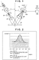
- Fig. 6 shows a specular gloss measuring method defined in JIS Z 8741.
- a light beam from a light source 1 is roughly condensed by a lens 2 to be condensed on a rectangular light source slit 31, which is set to have an aperture angle defined by the standard, and the light source slit 31 forms a secondary light source having the defined aperture angle.
- a light beam from the light source slit 31 is converted into a nearly parallel light beam by a lens 41, and a surface 10 is irradiated with the nearly parallel light beam.
- Light reflected by the surface 10 has a unique reflection pattern depending on a state of the surface 10, and is condensed again by a lens 42, thus forming an image of the light source slit 31 on a light-receiving slit 32.
- Light which has passed through the light-receiving slit 32, enters a light-receiving element 100, and is output as a photoelectric signal from the light-receiving element 100.
- a specular gloss measuring apparatus shown in Fig. 6 calculates a glossiness of the surface 10 using a relative intensity between the amount of light reflected by the surface 10 and an amount of light reflected by a reference surface, which amount is measured in advance.
- the specular gloss measuring apparatus shown in Fig. 6 can define brightness of reflection of a light source, but does not define a blurred degree of reflection of a light source, and cannot perfectly express the state of the surface 10.
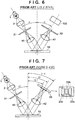
- Fig. 7 shows the arrangement of an apparatus for measuring a haze defined by ASTM E 430.
- a light beam from a light source 1 is roughly condensed by a lens 2 to be condensed on a light source slit 31, which is set to have an aperture angle defined by the standard, and the light source slit 31 forms a secondary light source having the defined aperture angle.
- a light beam from the light source slit 31 is converted into a nearly parallel light beam by a lens 41, and a surface 10 is irradiated with the nearly parallel light beam.
- Light reflected by the surface 10 has a unique reflection pattern depending on a state of the surface 10, and is condensed again by a lens 42, thus forming an image of the light source slit 31 on a light-receiving slit 33.
- Light, which has passed through the light-receiving slit 33 enters a light-receiving element, and is output as a photoelectric signal.
- the light-receiving slit 33 includes three slits 33a, 33b, and 33c, which are set at 18.1°, 20°, and 21.9° with respect to a perpendicular to the surface 10.
- the slit 33b is used to measure a specular gloss
- the slits 33a and 33c are used to measure a haze.
- the haze is an index indicating a degree of image unclearness.
- an angle difference from specular reflected light of the slits 33a and 33c is small, a state of the surface 10 suitable for measurement of a haze is limited.
- a reflection image exhibits unclearness beyond recognition, it is difficult to calculate a haze from the measurement result of the measuring apparatus shown in Fig. 7 .
- a distinctness-of-image gloss is measured using an apparatus having the same arrangement as that shown in Fig. 7 except for dimensions of the slits and a value calculation formula. More specifically, angles of the slits 33a, 33b, and 33c with respect to the perpendicular to the surface 10 are 19.7°, 20°, and 20.3°, and slit sizes are different. Like in measurement of a haze and the like, it is difficult for the surface 10 whose reflection image exhibits unclearness beyond recognition to calculate a distinctness-of-image gloss.
- Fig. 8 shows the arrangement of an apparatus used in an image clarity test method defined by JIS K 7374.
- a light beam from a light source 1 passes through a slit 31 and enters a lens 41 to be converted into parallel light, with which a surface 10 is irradiated. Reflected light by the surface 10 has a unique reflection pattern depending on a state of the surface 10, and is condensed again by a lens 42, thus forming an image of the light source slit 31 on a comb-tooth slit 50.
- the comb-tooth slit 50 is configured by five types of slits having different pitches.
- Contrast values are acquired by calculating maximum and minimum transmitted light amounts upon moving the comb-tooth slit 50 in a slit array direction, thus expressing the state of the surface 10 by five contrast values. Since the image clarity measuring method evaluates the clearness of a reflection image using contrast values, the brightness of the reflection image cannot be discussed.
- Japanese Patent Laid-Open No. 2008-256454 describes an apparatus and method for measuring a specular gloss of a surface
- Japanese Patent Laid-Open No. 2007-24655 describes an apparatus and method for measuring an image clarity of a surface.
- the measuring apparatuses defined by the respective standards have respective features, and measure different target reflection characteristics of a surface.
- Japanese Patent Laid-Open Nos. 2008-256454 and 2007-24655 disclose the apparatuses and methods for measuring reflection characteristics of a surface.
- these apparatuses and methods can only measure limited reflection characteristics of the surface. Therefore, the user in need of various reflection characteristics of a surface, has to prepare for measuring apparatuses of a plurality of methods, and has to selectively use them depending on the situation. For this reason, the user requires cost for purchasing a plurality of apparatuses, and a place for housing the plurality of apparatuses, thus imposing a load on the user.
- US 2008/246969 describes an apparatus for measuring an optical property of a surface.
- the apparatus aims to reduce errors caused by misplacing of a sample surface to be measured. Instead of using an aperture at the sensing side, the apparatus forms a distribution function corresponding to light arriving at the optical sensor and then integrates the distribution function within a range that would have corresponding to the sensing-side aperture in order to reach a measurement of the optical property.
- the present invention provides, for example, a technique which enables a single measuring apparatus to measure a plurality of types of reflection characteristics of a surface.
- the present invention provides a measuring apparatus as specified in any of accompanying claims 1 to 12.
- a second aspect of the present invention provides a measuring method according to claim 13.
- Fig. 1 shows a schematic arrangement of a measuring apparatus for measuring a reflection characteristic of a surface according to the first embodiment.
- An illumination device from a light source 1 to a lens 41 and a light-receiving device from a lens 42 to a two-dimensional light-receiving element (detector) 100 are disposed to respectively have angles ⁇ and ⁇ ' with respect to a perpendicular to a surface 10.
- the incident angle ⁇ and reflection angle ⁇ ' are set for each standard to be compliant with that standard which defines a reflection characteristic of the surface 10.
- the incident angle ⁇ and light-receiving angle ⁇ ' are set at any of 20°, 45°, 60°, and 85°.
- the incident angle ⁇ and reflection angle ⁇ ' are set at 20°.
- the incident angle ⁇ and reflection angle ⁇ ' are set at any of 45° and 60°.
- the incident angle ⁇ and reflection angle ⁇ ' are set at 20°.
- a light beam emitted from the light source 1 is condensed on a stop 31 having a circular aperture of ⁇ 1mm by a lens 2.
- an image of the light source 1 is temporarily formed as a circular secondary light source (surface light source) of ⁇ 1mm.
- a light beam emitted from the stop 31 becomes a diverging light beam again, and is converted into parallel light by the lens 41, thus illuminating the surface 10.
- Reflected light from the surface 10 has a unique reflection pattern depending on the reflection characteristic of the surface 10, and is received by a light-receiving surface of the two-dimensional light-receiving element 100.
- the two-dimensional light-receiving element 100 detects an intensity distribution of light formed on the light-receiving surface by the reflected light form the surface 10, and outputs first data to a processor 110. More specifically, the first data is a reflection pattern like a BRDF 1 with which an intensity changes according to an angle.
- the BRDF Bidirectional Reflectance Distribution Function
- a BRDF at a certain point on an object surface depends on two directions, that is, incident and reflection directions, and is defined as a ratio of an intensity of reflected light in an observation direction to that of incident light from an illumination direction.
- a signal received by the two-dimensional light-receiving element 100 can express a reflection characteristic unique to the surface 10 by trimming an output along an AA section on the two-dimensional light-receiving element 100.
- the intensity distribution of reflected light received by the two-dimensional light-receiving element 100 is trimmed along the AA section to cope with calculations of the respective standards which define the reflection characteristics.
- an anisotropy of the reflection characteristic of the surface 10 can also be measured.
- the reflection pattern BRDF 1 received by the two-dimensional light-receiving element 100 is obtained by combining a BRDF 1A by specular reflected light and a BRDF 1B by diffuse reflected light, as shown in Fig. 2 .
- the specular reflected light is also called surface reflected light
- the diffuse reflected light is also called scattered light.
- the BRDF 1B by diffuse reflected light corresponds to so-called a background color and brightness of the surface 10, and seems to have equal brightness independently of a visual line angle, the brightness is expressed by a model which is proportional to COS ⁇ with respect to a visual line angle ⁇ , and is called Lambert scattering.
- the BRDF 1A by specular reflected light corresponds to a state of reflection of the light source 1, is normally modeled by a Gaussian distribution, and is defined by a spread degree and intensity of the distribution as parameters.
- the light intensity distribution BRDF 1A by specular reflected light when the circular aperture is used changes from a BRDF 1Aa to a BRDF 1Ad during processes in which the surface 10 transits from a specular surface to a scattering surface, as shown in Fig. 3 .
- the surface 10 is a specular surface
- a rectangular BRDF 1Aa with a sharp edge is output.
- the rectangular shape is broken, and a nearly Gaussian distribution like a BRDF 1Ad is finally output.
- BRDFs 1Aa to 1Ad surfaces 10 which exhibit reflection patterns of BRDFs 1Aa to 1Ad by specular reflected light when the surface 10 is irradiated with light using the stop 31 having the circular aperture.
- BRDFs 2 by specular reflected light obtained by the two-dimensional light-receiving element 100 when a point light source (for example, a light source of ⁇ 10 ⁇ m is disposed at one of a plurality of positions in a plane of the stop 31 and the surfaces 10a to 10d are illuminated with light coming from that light source will be respectively referred to as BRDFs 2a to 2d.
- the BRDFs 2a to 2d are simple Gaussian distribution patterns in which only a spread degree and intensity are changed during transition processes from specular surfaces to scattering surfaces of the surfaces 10a to 10d.
- the BRDFs 2a to 2d can be estimated from addition calculations under the assumption that the circular aperture of the stop 31 is a set of point light sources.
- the BRDFs 2a to 2d can be calculated via actual measurements by arranging a point light source at each of the plurality of positions in the plane of the stop 31.
- information indicating the relationship between the BRDFs 1Aa to 1Ad and the BRDFs 2a to 2d is acquired in advance by calculations or actual measurements, and is stored in a memory 120 of the measuring apparatus.
- a size ⁇ of a point light source is set to fall within a range of several ⁇ m to several ten ⁇ m, and a blurred pattern on the two-dimensional light-receiving element 100 is modeled by being approximated to a Gaussian distribution.
- a blurred image of the circular aperture on the two-dimensional light-receiving element 100 can be assumed to be a set of blurred images of the point light sources.
- Sum totals of light intensities obtained from the respective point light sources as many as the numbers of point light sources on a plane coordinate system on the two-dimensional light-receiving element 100 are equal to the BRDFs 1Aa to 1Ad.
- the BRDFs 2a to 2d can be calculated (back-calculated) from actually measured values of the BRDFs 1Aa to 1Ad.
- the BRDF 1A by specular reflected light when the stop 31 having the circular aperture is used and the reflection pattern BRDF 2 of a point light source can be associated with each other using, for example, a half width and peak ratio of the reflection pattern. Also, since the half width of the reflection pattern is not monotonically increased near specular reflection during blurring processes of an image, the BRDF 1A may be associated with the BRDF 2 using a width other than the half width, for example, a 1/3 width of a peak. The width of the peak used in association with the BRDF 2 may be other widths such as a 1/4 width in addition to the 1/3 width.
- the processor 110 can calculate the reflection pattern BRDF 2 of the point light source from the BRDF 1A.
- the obtained light amount is only about 1/10000 of that obtained when the stop 31 having the circular aperture is used. For this reason, it becomes difficult to precisely measure reflection profiles, or an accumulation time of the two-dimensional light-receiving element 100 has to be prolonged, resulting in a low throughput. Therefore, it is very effective to dispose the stop 31 having the circular aperture of ⁇ 1mm or more, and to calculate the reflection pattern BRDF 2 of the point light source by calculations in terms of signal quality.
- the processor 110 divides the BRDF 1 into the BRDF 1A by specular reflected light and the BRDF 1B by diffuse reflected light, and then calculates a correlation between the BRDF 1A and the reflection pattern BRDF 2 by specular reflected light of the point light source.
- the processor 110 estimates, based on the BRDF 1, data of the light intensity distribution formed on the light-receiving surface by reflected light when a point light source is disposed at one of a plurality of positions of the circular aperture of the stop 31.
- the processor 110 can calculate the BRDF 2 (second data) by specular reflected light and a BRDF 3 (third data) by diffuse reflected light by dividing the estimated data.
- the processor 110 can calculate the BRDF 3 based on the BRDF 1B by diffuse reflected light and a ratio between the size of the point light source and the circular aperture of the stop 31.
- the BRDF 1B by diffuse reflected light will be described below.
- diffuse reflected light can be modeled by being approximated to Lambert scattering.
- the Lambert scattering defines that a reflected light amount ratio to an angle ⁇ is COS ⁇ based on the fact that the brightness of object on a perfectly diffusing surface (perfect diffuse surface or Lambertian surface) is constant independently of a visual line.
- the BRDF 3 based on the BRDF 1B by diffuse reflected light can be estimated by giving parameters of the diffuse reflectance. Since levels of specular reflected light and diffuse reflected light to be mixed are determined by an area of the light source 1, the diffuse reflectance and the area of the light source 1 can be used in calculations to be described later when they are stored in the memory 120.
- a measuring condition of a settable reflection characteristic includes a shape and size of an arbitrary light source, an arbitrary evaluation region on the light-receiving surface, an incident angle of parallel light, and the like.
- an aperture on the light source side is a rectangle having a width of 0.75° and a length of 2.5°, which are defined by an aperture angle.
- F of the lens 41 and an aperture angle ⁇ a size of the aperture on the light source side can be calculated by F ⁇ COS ⁇ . Therefore, if the focal length is 50mm, it can be calculated that a rectangular slit having a width of 0.65mm and a length of 2.18mm is required as the aperture on the light source side.
- a reflection pattern by specular reflected light on the two-dimensional light-receiving element 100 when this rectangular slit is used can be calculated by the processor 110 by adding light amounts on a two-dimensional space to have the rectangular slit of the width of 0.65mm and the length of 2.18mm as a set of point light sources of ⁇ 10 ⁇ m.
- a calculated reflected light pattern on the two-dimensional light-receiving element 100 when the apparatus arrangement of the specular gloss measuring method is adopted can be obtained by the measuring apparatus of the first embodiment.
- a light amount, which enters a light-receiving side area having a width of 1.8° and a length of 3.6°, which are defined by an aperture angle has to be calculated.
- that light amount can be easily calculated from the calculated reflected light pattern on the two-dimensional light-receiving element 100.
- a light irradiation direction in the measuring apparatus is configured to be changed to 20°, 45°, 60°, and 85° like in a conventionally manufactured specular gloss measuring apparatus
- evaluation values specified in various standards in association with a specular gloss, haze, image clarity, and distinctness-of-image gloss can be acquired by a single measuring apparatus.
- the measuring apparatus of the first embodiment can acquire various reflection characteristics of the surface 10, the user need not selectively use a plurality of apparatuses depending on types of reflection characteristics. Also, since the measuring apparatus of the first embodiment uses, as the light source 1, a light source having a certain size in place of a point light source, it is effective in terms of S/N, thus allowing measurements within a short period of time.
- Fig. 4 shows a schematic arrangement of a measuring apparatus according to the second embodiment.
- a stop 31 has a rectangular slit in place of a circular aperture.
- the rectangular slit of the stop 31 has an aperture angle of 0.75° in a widthwise direction and that of 2.5° in a lengthwise direction, which are defined in the standard required to measure a specular gloss.
- a specular gloss which matches the standard of a specular gloss measuring method can be easily acquired.
- a haze measurement since the aperture angle on the light source side, which is designated by the standard, is the same, a haze can be easily acquired.
- a reflection pattern BRDF 2 of a point light source can be calculated or associated by advanced measurements from a BRDF 1A by specular reflected light upon trimming along an AA section of the two-dimensional light-receiving element 100. Therefore, even when the measuring apparatus of the second embodiment is used, an image clarity can be measured.
- the measuring apparatus of the second embodiment requires a smaller calculation volume than that of the first embodiment, and is further effective in that the apparatus arrangement perfectly matches the standard upon measuring a specular gloss and haze.
- the measuring apparatus of the second embodiment can cope with measurements in only one direction.
- a one-dimensional light-receiving element may be disposed in a direction of AA in place of the two-dimensional light-receiving element 100.
- a load on signal processing can be reduced.
- Fig. 5 shows a schematic arrangement of a measuring apparatus according to the third embodiment.
- a stop 31 has a hexagonal aperture in place of a circular aperture or rectangular slit.
- reflection patterns in three directions perpendicular to three pairs of sides of a hexagon can be measured.
- a specular gloss, haze, and image clarity can be measured.
- the measuring apparatus of the third embodiment can measure reflection patterns in two directions different from an AA section, in addition to measurements that match the standards it can also make determination when a reflection pattern has an anisotropy.
- the stop 31 has a hexagonal aperture, but it may have an n-sided polygonal aperture other than the hexagonal aperture.
- the n-sided polygon is desirably an even-sided polygon (especially, a regular even-sided polygon) in terms of symmetry.
Landscapes
- Physics & Mathematics (AREA)
- Health & Medical Sciences (AREA)
- Life Sciences & Earth Sciences (AREA)
- Chemical & Material Sciences (AREA)
- Analytical Chemistry (AREA)
- Biochemistry (AREA)
- General Health & Medical Sciences (AREA)
- General Physics & Mathematics (AREA)
- Immunology (AREA)
- Pathology (AREA)
- Investigating Or Analysing Materials By Optical Means (AREA)
Applications Claiming Priority (1)
| Application Number | Priority Date | Filing Date | Title |
|---|---|---|---|
| JP2012281756A JP6053506B2 (ja) | 2012-12-25 | 2012-12-25 | 反射特性の測定装置 |
Publications (2)
| Publication Number | Publication Date |
|---|---|
| EP2749865A1 EP2749865A1 (en) | 2014-07-02 |
| EP2749865B1 true EP2749865B1 (en) | 2021-02-17 |
Family
ID=50064332
Family Applications (1)
| Application Number | Title | Priority Date | Filing Date |
|---|---|---|---|
| EP13197240.8A Active EP2749865B1 (en) | 2012-12-25 | 2013-12-13 | Reflection characteristic measuring apparatus |
Country Status (3)
| Country | Link |
|---|---|
| US (2) | US8976361B2 (ja) |
| EP (1) | EP2749865B1 (ja) |
| JP (1) | JP6053506B2 (ja) |
Families Citing this family (11)
| Publication number | Priority date | Publication date | Assignee | Title |
|---|---|---|---|---|
| JP6635674B2 (ja) * | 2015-05-11 | 2020-01-29 | キヤノン株式会社 | 計測装置、計測方法およびプログラム |
| JP6657794B2 (ja) * | 2015-10-30 | 2020-03-04 | 大日本印刷株式会社 | 光拡散度測定装置及び光拡散度測定方法 |
| FR3049709B1 (fr) * | 2016-04-05 | 2019-08-30 | Areva Np | Procede de detection d'un defaut sur une surface par eclairage multidirectionnel et dispositif associe |
| JP6894672B2 (ja) | 2016-05-18 | 2021-06-30 | キヤノン株式会社 | 情報処理装置、情報処理方法、プログラム |
| JP6682350B2 (ja) * | 2016-05-18 | 2020-04-15 | キヤノン株式会社 | 情報処理装置、制御装置、情報処理方法、制御方法、並びにプログラム |
| JP6776004B2 (ja) * | 2016-05-26 | 2020-10-28 | キヤノン株式会社 | 画像処理装置、画像処理方法およびプログラム |
| DE102016220290A1 (de) * | 2016-10-18 | 2018-04-19 | Robert Bosch Gmbh | Verfahren und Vorrichtung zum Erkennen eines direkten Lichtreflexionsstrahls von einem Objekt auf einen Lichtsensor |
| JP6557688B2 (ja) * | 2017-01-13 | 2019-08-07 | キヤノン株式会社 | 計測装置、情報処理装置、情報処理方法、およびプログラム |
| CN107478612B (zh) * | 2017-09-20 | 2023-08-04 | 安费诺(常州)连接系统有限公司 | 用于检测过滤器积尘的传感器及方法 |
| JP2019207175A (ja) | 2018-05-30 | 2019-12-05 | キヤノン株式会社 | 測定装置 |
| JP7446725B2 (ja) | 2019-06-28 | 2024-03-11 | キヤノン株式会社 | 測定装置、測定方法、および、プログラム |
Family Cites Families (14)
| Publication number | Priority date | Publication date | Assignee | Title |
|---|---|---|---|---|
| JP2915192B2 (ja) * | 1991-11-26 | 1999-07-05 | 川崎製鉄株式会社 | 薄塗装用金属板の評価方法及び薄塗装塗膜鮮映性に優れた薄塗装用金属板 |
| JPH08247858A (ja) * | 1995-03-07 | 1996-09-27 | Toshiba Corp | 光温度分布センサ及び温度分布測定方法 |
| WO1998037811A1 (en) * | 1997-02-28 | 1998-09-03 | Electro-Optical Sciences, Inc. | Systems and methods for the multispectral imaging and characterization of skin tissue |
| JP3768052B2 (ja) * | 1999-12-14 | 2006-04-19 | 株式会社リコー | カラー画像処理方法、カラー画像処理装置、及びそのための記録媒体 |
| JP4073200B2 (ja) * | 2001-11-08 | 2008-04-09 | 富士フイルム株式会社 | 画像記録方法およびインクジェットプリンタ |
| JP2003302211A (ja) * | 2002-04-11 | 2003-10-24 | Canon Inc | 3次元画像処理装置及び方法 |
| JP3938184B2 (ja) * | 2005-03-22 | 2007-06-27 | キヤノン株式会社 | 情報処理方法及びその装置 |
| JP2007024655A (ja) | 2005-07-15 | 2007-02-01 | Canon Inc | 写像性測定方法および装置 |
| JP2008145225A (ja) * | 2006-12-08 | 2008-06-26 | Konica Minolta Sensing Inc | 光学特性測定方法及び光学特性測定装置 |
| JP2008256454A (ja) * | 2007-04-03 | 2008-10-23 | Konica Minolta Sensing Inc | 光学特性測定装置および該方法 |
| JP5202150B2 (ja) * | 2008-07-16 | 2013-06-05 | キヤノン株式会社 | 画像処理装置およびその方法 |
| JP2010145198A (ja) * | 2008-12-18 | 2010-07-01 | Seiko Epson Corp | 画質の計算方法、画質検査装置およびプログラム |
| JP5591017B2 (ja) * | 2010-08-09 | 2014-09-17 | キヤノン株式会社 | 画像処理装置および画像処理方法 |
| JP5636885B2 (ja) * | 2010-11-08 | 2014-12-10 | 株式会社リコー | 画像処理装置、画像形成装置、及び画像処理システム |
-
2012
- 2012-12-25 JP JP2012281756A patent/JP6053506B2/ja active Active
-
2013
- 2013-12-13 EP EP13197240.8A patent/EP2749865B1/en active Active
- 2013-12-23 US US14/138,369 patent/US8976361B2/en not_active Expired - Fee Related
-
2015
- 2015-02-04 US US14/613,526 patent/US9528934B2/en active Active
Non-Patent Citations (1)
| Title |
|---|
| None * |
Also Published As
| Publication number | Publication date |
|---|---|
| JP2014126408A (ja) | 2014-07-07 |
| US20140176953A1 (en) | 2014-06-26 |
| US9528934B2 (en) | 2016-12-27 |
| JP6053506B2 (ja) | 2016-12-27 |
| US8976361B2 (en) | 2015-03-10 |
| US20150153276A1 (en) | 2015-06-04 |
| EP2749865A1 (en) | 2014-07-02 |
Similar Documents
| Publication | Publication Date | Title |
|---|---|---|
| EP2749865B1 (en) | Reflection characteristic measuring apparatus | |
| US20200333247A1 (en) | Optical test apparatus and optical test method | |
| EP2241877A1 (en) | Analysis device and analysis method | |
| WO2003014711A1 (fr) | Puce de detection a resonance de plasmon de surface et procede et dispositif d'analyse d'echantillon utilisant cette puce | |
| JP2014126408A5 (ja) | ||
| US20090002718A1 (en) | Optical Measurement Device | |
| EP3159679A1 (en) | Apparatus and method for measuring haze of sheet materials or other materials using off-axis detector | |
| JP6542906B2 (ja) | 少なくとも部分的に透明な物体の表面に関連する表面データおよび/または測定データを決定するための方法および装置 | |
| JP4726433B2 (ja) | 表面特性を特定する装置および方法 | |
| US10740890B2 (en) | Image processing apparatus, method, and storage medium | |
| JP7308823B2 (ja) | 粒子径分布測定装置及び粒子径分布測定装置用プログラム | |
| JP7268678B2 (ja) | 光学特性測定装置 | |
| JP2018515747A5 (ja) | ||
| EP2913659B1 (en) | Optical system and apparatus for measuring optical quality of a surface | |
| US9250186B2 (en) | Profilometry systems and methods based on absorption and optical frequency conversion | |
| Inoue et al. | Point spread function of specular reflection and gonio-reflectance distribution | |
| US20190331600A1 (en) | Measurement apparatus, information processing apparatus, information processing method, and storage medium | |
| Tominaga et al. | Measurement and modeling of bidirectional characteristics of fluorescent objects | |
| JP2017190957A (ja) | 光学測定装置 | |
| WO2019230624A1 (ja) | 粒子径分布測定装置及び粒子径分布測定装置用プログラム | |
| JP2012088265A (ja) | 光沢度の測定方法及び測定装置 | |
| KR102132890B1 (ko) | 인증 장치 및 방법 | |
| RU2535519C2 (ru) | Способ бесконтактного измерения параметров шероховатости поверхности | |
| EP3757548A1 (en) | Reflection characteristic measurement device, corresponding method and non-transitory storage medium | |
| JP2007147368A (ja) | エッジ検出方法およびエッジ検出装置 |
Legal Events
| Date | Code | Title | Description |
|---|---|---|---|
| 17P | Request for examination filed |
Effective date: 20131213 |
|
| AK | Designated contracting states |
Kind code of ref document: A1 Designated state(s): AL AT BE BG CH CY CZ DE DK EE ES FI FR GB GR HR HU IE IS IT LI LT LU LV MC MK MT NL NO PL PT RO RS SE SI SK SM TR |
|
| AX | Request for extension of the european patent |
Extension state: BA ME |
|
| PUAI | Public reference made under article 153(3) epc to a published international application that has entered the european phase |
Free format text: ORIGINAL CODE: 0009012 |
|
| R17P | Request for examination filed (corrected) |
Effective date: 20150105 |
|
| RBV | Designated contracting states (corrected) |
Designated state(s): AL AT BE BG CH CY CZ DE DK EE ES FI FR GB GR HR HU IE IS IT LI LT LU LV MC MK MT NL NO PL PT RO RS SE SI SK SM TR |
|
| STAA | Information on the status of an ep patent application or granted ep patent |
Free format text: STATUS: EXAMINATION IS IN PROGRESS |
|
| 17Q | First examination report despatched |
Effective date: 20191008 |
|
| GRAP | Despatch of communication of intention to grant a patent |
Free format text: ORIGINAL CODE: EPIDOSNIGR1 |
|
| STAA | Information on the status of an ep patent application or granted ep patent |
Free format text: STATUS: GRANT OF PATENT IS INTENDED |
|
| INTG | Intention to grant announced |
Effective date: 20200707 |
|
| GRAS | Grant fee paid |
Free format text: ORIGINAL CODE: EPIDOSNIGR3 |
|
| GRAA | (expected) grant |
Free format text: ORIGINAL CODE: 0009210 |
|
| STAA | Information on the status of an ep patent application or granted ep patent |
Free format text: STATUS: THE PATENT HAS BEEN GRANTED |
|
| AK | Designated contracting states |
Kind code of ref document: B1 Designated state(s): AL AT BE BG CH CY CZ DE DK EE ES FI FR GB GR HR HU IE IS IT LI LT LU LV MC MK MT NL NO PL PT RO RS SE SI SK SM TR |
|
| REG | Reference to a national code |
Ref country code: GB Ref legal event code: FG4D |
|
| REG | Reference to a national code |
Ref country code: CH Ref legal event code: EP |
|
| REG | Reference to a national code |
Ref country code: DE Ref legal event code: R096 Ref document number: 602013075633 Country of ref document: DE |
|
| REG | Reference to a national code |
Ref country code: AT Ref legal event code: REF Ref document number: 1362089 Country of ref document: AT Kind code of ref document: T Effective date: 20210315 |
|
| REG | Reference to a national code |
Ref country code: IE Ref legal event code: FG4D |
|
| REG | Reference to a national code |
Ref country code: LT Ref legal event code: MG9D |
|
| REG | Reference to a national code |
Ref country code: NL Ref legal event code: MP Effective date: 20210217 |
|
| PG25 | Lapsed in a contracting state [announced via postgrant information from national office to epo] |
Ref country code: GR Free format text: LAPSE BECAUSE OF FAILURE TO SUBMIT A TRANSLATION OF THE DESCRIPTION OR TO PAY THE FEE WITHIN THE PRESCRIBED TIME-LIMIT Effective date: 20210518 Ref country code: HR Free format text: LAPSE BECAUSE OF FAILURE TO SUBMIT A TRANSLATION OF THE DESCRIPTION OR TO PAY THE FEE WITHIN THE PRESCRIBED TIME-LIMIT Effective date: 20210217 Ref country code: FI Free format text: LAPSE BECAUSE OF FAILURE TO SUBMIT A TRANSLATION OF THE DESCRIPTION OR TO PAY THE FEE WITHIN THE PRESCRIBED TIME-LIMIT Effective date: 20210217 Ref country code: PT Free format text: LAPSE BECAUSE OF FAILURE TO SUBMIT A TRANSLATION OF THE DESCRIPTION OR TO PAY THE FEE WITHIN THE PRESCRIBED TIME-LIMIT Effective date: 20210617 Ref country code: LT Free format text: LAPSE BECAUSE OF FAILURE TO SUBMIT A TRANSLATION OF THE DESCRIPTION OR TO PAY THE FEE WITHIN THE PRESCRIBED TIME-LIMIT Effective date: 20210217 Ref country code: BG Free format text: LAPSE BECAUSE OF FAILURE TO SUBMIT A TRANSLATION OF THE DESCRIPTION OR TO PAY THE FEE WITHIN THE PRESCRIBED TIME-LIMIT Effective date: 20210517 Ref country code: NO Free format text: LAPSE BECAUSE OF FAILURE TO SUBMIT A TRANSLATION OF THE DESCRIPTION OR TO PAY THE FEE WITHIN THE PRESCRIBED TIME-LIMIT Effective date: 20210517 |
|
| REG | Reference to a national code |
Ref country code: AT Ref legal event code: MK05 Ref document number: 1362089 Country of ref document: AT Kind code of ref document: T Effective date: 20210217 |
|
| PG25 | Lapsed in a contracting state [announced via postgrant information from national office to epo] |
Ref country code: NL Free format text: LAPSE BECAUSE OF FAILURE TO SUBMIT A TRANSLATION OF THE DESCRIPTION OR TO PAY THE FEE WITHIN THE PRESCRIBED TIME-LIMIT Effective date: 20210217 Ref country code: LV Free format text: LAPSE BECAUSE OF FAILURE TO SUBMIT A TRANSLATION OF THE DESCRIPTION OR TO PAY THE FEE WITHIN THE PRESCRIBED TIME-LIMIT Effective date: 20210217 Ref country code: RS Free format text: LAPSE BECAUSE OF FAILURE TO SUBMIT A TRANSLATION OF THE DESCRIPTION OR TO PAY THE FEE WITHIN THE PRESCRIBED TIME-LIMIT Effective date: 20210217 Ref country code: PL Free format text: LAPSE BECAUSE OF FAILURE TO SUBMIT A TRANSLATION OF THE DESCRIPTION OR TO PAY THE FEE WITHIN THE PRESCRIBED TIME-LIMIT Effective date: 20210217 Ref country code: SE Free format text: LAPSE BECAUSE OF FAILURE TO SUBMIT A TRANSLATION OF THE DESCRIPTION OR TO PAY THE FEE WITHIN THE PRESCRIBED TIME-LIMIT Effective date: 20210217 |
|
| PG25 | Lapsed in a contracting state [announced via postgrant information from national office to epo] |
Ref country code: IS Free format text: LAPSE BECAUSE OF FAILURE TO SUBMIT A TRANSLATION OF THE DESCRIPTION OR TO PAY THE FEE WITHIN THE PRESCRIBED TIME-LIMIT Effective date: 20210617 |
|
| PG25 | Lapsed in a contracting state [announced via postgrant information from national office to epo] |
Ref country code: SM Free format text: LAPSE BECAUSE OF FAILURE TO SUBMIT A TRANSLATION OF THE DESCRIPTION OR TO PAY THE FEE WITHIN THE PRESCRIBED TIME-LIMIT Effective date: 20210217 Ref country code: AT Free format text: LAPSE BECAUSE OF FAILURE TO SUBMIT A TRANSLATION OF THE DESCRIPTION OR TO PAY THE FEE WITHIN THE PRESCRIBED TIME-LIMIT Effective date: 20210217 Ref country code: CZ Free format text: LAPSE BECAUSE OF FAILURE TO SUBMIT A TRANSLATION OF THE DESCRIPTION OR TO PAY THE FEE WITHIN THE PRESCRIBED TIME-LIMIT Effective date: 20210217 Ref country code: EE Free format text: LAPSE BECAUSE OF FAILURE TO SUBMIT A TRANSLATION OF THE DESCRIPTION OR TO PAY THE FEE WITHIN THE PRESCRIBED TIME-LIMIT Effective date: 20210217 |
|
| REG | Reference to a national code |
Ref country code: DE Ref legal event code: R097 Ref document number: 602013075633 Country of ref document: DE |
|
| PG25 | Lapsed in a contracting state [announced via postgrant information from national office to epo] |
Ref country code: SK Free format text: LAPSE BECAUSE OF FAILURE TO SUBMIT A TRANSLATION OF THE DESCRIPTION OR TO PAY THE FEE WITHIN THE PRESCRIBED TIME-LIMIT Effective date: 20210217 Ref country code: DK Free format text: LAPSE BECAUSE OF FAILURE TO SUBMIT A TRANSLATION OF THE DESCRIPTION OR TO PAY THE FEE WITHIN THE PRESCRIBED TIME-LIMIT Effective date: 20210217 Ref country code: ES Free format text: LAPSE BECAUSE OF FAILURE TO SUBMIT A TRANSLATION OF THE DESCRIPTION OR TO PAY THE FEE WITHIN THE PRESCRIBED TIME-LIMIT Effective date: 20210217 Ref country code: RO Free format text: LAPSE BECAUSE OF FAILURE TO SUBMIT A TRANSLATION OF THE DESCRIPTION OR TO PAY THE FEE WITHIN THE PRESCRIBED TIME-LIMIT Effective date: 20210217 |
|
| PLBE | No opposition filed within time limit |
Free format text: ORIGINAL CODE: 0009261 |
|
| STAA | Information on the status of an ep patent application or granted ep patent |
Free format text: STATUS: NO OPPOSITION FILED WITHIN TIME LIMIT |
|
| 26N | No opposition filed |
Effective date: 20211118 |
|
| PG25 | Lapsed in a contracting state [announced via postgrant information from national office to epo] |
Ref country code: AL Free format text: LAPSE BECAUSE OF FAILURE TO SUBMIT A TRANSLATION OF THE DESCRIPTION OR TO PAY THE FEE WITHIN THE PRESCRIBED TIME-LIMIT Effective date: 20210217 |
|
| PGFP | Annual fee paid to national office [announced via postgrant information from national office to epo] |
Ref country code: GB Payment date: 20211118 Year of fee payment: 9 |
|
| PG25 | Lapsed in a contracting state [announced via postgrant information from national office to epo] |
Ref country code: SI Free format text: LAPSE BECAUSE OF FAILURE TO SUBMIT A TRANSLATION OF THE DESCRIPTION OR TO PAY THE FEE WITHIN THE PRESCRIBED TIME-LIMIT Effective date: 20210217 |
|
| PG25 | Lapsed in a contracting state [announced via postgrant information from national office to epo] |
Ref country code: IT Free format text: LAPSE BECAUSE OF FAILURE TO SUBMIT A TRANSLATION OF THE DESCRIPTION OR TO PAY THE FEE WITHIN THE PRESCRIBED TIME-LIMIT Effective date: 20210217 |
|
| PG25 | Lapsed in a contracting state [announced via postgrant information from national office to epo] |
Ref country code: IS Free format text: LAPSE BECAUSE OF FAILURE TO SUBMIT A TRANSLATION OF THE DESCRIPTION OR TO PAY THE FEE WITHIN THE PRESCRIBED TIME-LIMIT Effective date: 20210617 |
|
| REG | Reference to a national code |
Ref country code: DE Ref legal event code: R119 Ref document number: 602013075633 Country of ref document: DE |
|
| PG25 | Lapsed in a contracting state [announced via postgrant information from national office to epo] |
Ref country code: MC Free format text: LAPSE BECAUSE OF FAILURE TO SUBMIT A TRANSLATION OF THE DESCRIPTION OR TO PAY THE FEE WITHIN THE PRESCRIBED TIME-LIMIT Effective date: 20210217 |
|
| REG | Reference to a national code |
Ref country code: CH Ref legal event code: PL |
|
| REG | Reference to a national code |
Ref country code: BE Ref legal event code: MM Effective date: 20211231 |
|
| PG25 | Lapsed in a contracting state [announced via postgrant information from national office to epo] |
Ref country code: LU Free format text: LAPSE BECAUSE OF NON-PAYMENT OF DUE FEES Effective date: 20211213 Ref country code: IE Free format text: LAPSE BECAUSE OF NON-PAYMENT OF DUE FEES Effective date: 20211213 Ref country code: DE Free format text: LAPSE BECAUSE OF NON-PAYMENT OF DUE FEES Effective date: 20220701 |
|
| PG25 | Lapsed in a contracting state [announced via postgrant information from national office to epo] |
Ref country code: FR Free format text: LAPSE BECAUSE OF NON-PAYMENT OF DUE FEES Effective date: 20211231 Ref country code: BE Free format text: LAPSE BECAUSE OF NON-PAYMENT OF DUE FEES Effective date: 20211231 |
|
| PG25 | Lapsed in a contracting state [announced via postgrant information from national office to epo] |
Ref country code: LI Free format text: LAPSE BECAUSE OF NON-PAYMENT OF DUE FEES Effective date: 20211231 Ref country code: CH Free format text: LAPSE BECAUSE OF NON-PAYMENT OF DUE FEES Effective date: 20211231 |
|
| PG25 | Lapsed in a contracting state [announced via postgrant information from national office to epo] |
Ref country code: HU Free format text: LAPSE BECAUSE OF FAILURE TO SUBMIT A TRANSLATION OF THE DESCRIPTION OR TO PAY THE FEE WITHIN THE PRESCRIBED TIME-LIMIT; INVALID AB INITIO Effective date: 20131213 |
|
| PG25 | Lapsed in a contracting state [announced via postgrant information from national office to epo] |
Ref country code: CY Free format text: LAPSE BECAUSE OF FAILURE TO SUBMIT A TRANSLATION OF THE DESCRIPTION OR TO PAY THE FEE WITHIN THE PRESCRIBED TIME-LIMIT Effective date: 20210217 |
|
| GBPC | Gb: european patent ceased through non-payment of renewal fee |
Effective date: 20221213 |
|
| PG25 | Lapsed in a contracting state [announced via postgrant information from national office to epo] |
Ref country code: GB Free format text: LAPSE BECAUSE OF NON-PAYMENT OF DUE FEES Effective date: 20221213 |
|
| PG25 | Lapsed in a contracting state [announced via postgrant information from national office to epo] |
Ref country code: MK Free format text: LAPSE BECAUSE OF FAILURE TO SUBMIT A TRANSLATION OF THE DESCRIPTION OR TO PAY THE FEE WITHIN THE PRESCRIBED TIME-LIMIT Effective date: 20210217 |