EP2734758B1 - Multi-vane throttle valve - Google Patents
Multi-vane throttle valve Download PDFInfo
- Publication number
- EP2734758B1 EP2734758B1 EP12814127.2A EP12814127A EP2734758B1 EP 2734758 B1 EP2734758 B1 EP 2734758B1 EP 12814127 A EP12814127 A EP 12814127A EP 2734758 B1 EP2734758 B1 EP 2734758B1
- Authority
- EP
- European Patent Office
- Prior art keywords
- vane
- chamber
- rotatable
- conduit
- throttling valve
- Prior art date
- Legal status (The legal status is an assumption and is not a legal conclusion. Google has not performed a legal analysis and makes no representation as to the accuracy of the status listed.)
- Active
Links
- 238000001816 cooling Methods 0.000 claims description 59
- 238000000034 method Methods 0.000 claims description 38
- 230000008569 process Effects 0.000 claims description 33
- 239000012530 fluid Substances 0.000 claims description 17
- 230000007246 mechanism Effects 0.000 claims description 10
- 239000007789 gas Substances 0.000 claims description 9
- 238000012545 processing Methods 0.000 claims description 9
- 238000004891 communication Methods 0.000 claims description 7
- 239000011553 magnetic fluid Substances 0.000 claims description 7
- 239000000110 cooling liquid Substances 0.000 claims description 2
- XLYOFNOQVPJJNP-UHFFFAOYSA-N water Substances O XLYOFNOQVPJJNP-UHFFFAOYSA-N 0.000 claims description 2
- 239000002826 coolant Substances 0.000 description 44
- 239000012809 cooling fluid Substances 0.000 description 13
- 229910001220 stainless steel Inorganic materials 0.000 description 5
- 239000010935 stainless steel Substances 0.000 description 5
- 230000037361 pathway Effects 0.000 description 4
- 238000007789 sealing Methods 0.000 description 3
- 230000032258 transport Effects 0.000 description 3
- RYGMFSIKBFXOCR-UHFFFAOYSA-N Copper Chemical compound [Cu] RYGMFSIKBFXOCR-UHFFFAOYSA-N 0.000 description 2
- 229910052802 copper Inorganic materials 0.000 description 2
- 239000010949 copper Substances 0.000 description 2
- 238000012423 maintenance Methods 0.000 description 2
- 230000004048 modification Effects 0.000 description 2
- 238000012986 modification Methods 0.000 description 2
- 230000008439 repair process Effects 0.000 description 2
- 238000000429 assembly Methods 0.000 description 1
- 230000000712 assembly Effects 0.000 description 1
- 238000005219 brazing Methods 0.000 description 1
- 238000005229 chemical vapour deposition Methods 0.000 description 1
- 239000011248 coating agent Substances 0.000 description 1
- 238000000576 coating method Methods 0.000 description 1
- 239000000498 cooling water Substances 0.000 description 1
- 230000008878 coupling Effects 0.000 description 1
- 238000010168 coupling process Methods 0.000 description 1
- 238000005859 coupling reaction Methods 0.000 description 1
- 239000004078 cryogenic material Substances 0.000 description 1
- 230000001419 dependent effect Effects 0.000 description 1
- 238000013461 design Methods 0.000 description 1
- 230000000694 effects Effects 0.000 description 1
- 238000010348 incorporation Methods 0.000 description 1
- 239000007788 liquid Substances 0.000 description 1
- 238000004519 manufacturing process Methods 0.000 description 1
- 239000000463 material Substances 0.000 description 1
- 230000013011 mating Effects 0.000 description 1
- 239000002184 metal Substances 0.000 description 1
- 229910052751 metal Inorganic materials 0.000 description 1
- 239000007769 metal material Substances 0.000 description 1
- 229910052755 nonmetal Inorganic materials 0.000 description 1
- 230000004044 response Effects 0.000 description 1
- 239000000126 substance Substances 0.000 description 1
- 238000012546 transfer Methods 0.000 description 1
Images


Classifications
-
- F—MECHANICAL ENGINEERING; LIGHTING; HEATING; WEAPONS; BLASTING
- F16—ENGINEERING ELEMENTS AND UNITS; GENERAL MEASURES FOR PRODUCING AND MAINTAINING EFFECTIVE FUNCTIONING OF MACHINES OR INSTALLATIONS; THERMAL INSULATION IN GENERAL
- F16K—VALVES; TAPS; COCKS; ACTUATING-FLOATS; DEVICES FOR VENTING OR AERATING
- F16K51/00—Other details not peculiar to particular types of valves or cut-off apparatus
- F16K51/02—Other details not peculiar to particular types of valves or cut-off apparatus specially adapted for high-vacuum installations
-
- F—MECHANICAL ENGINEERING; LIGHTING; HEATING; WEAPONS; BLASTING
- F16—ENGINEERING ELEMENTS AND UNITS; GENERAL MEASURES FOR PRODUCING AND MAINTAINING EFFECTIVE FUNCTIONING OF MACHINES OR INSTALLATIONS; THERMAL INSULATION IN GENERAL
- F16K—VALVES; TAPS; COCKS; ACTUATING-FLOATS; DEVICES FOR VENTING OR AERATING
- F16K1/00—Lift valves or globe valves, i.e. cut-off apparatus with closure members having at least a component of their opening and closing motion perpendicular to the closing faces
- F16K1/16—Lift valves or globe valves, i.e. cut-off apparatus with closure members having at least a component of their opening and closing motion perpendicular to the closing faces with pivoted closure-members
- F16K1/18—Lift valves or globe valves, i.e. cut-off apparatus with closure members having at least a component of their opening and closing motion perpendicular to the closing faces with pivoted closure-members with pivoted discs or flaps
- F16K1/22—Lift valves or globe valves, i.e. cut-off apparatus with closure members having at least a component of their opening and closing motion perpendicular to the closing faces with pivoted closure-members with pivoted discs or flaps with axis of rotation crossing the valve member, e.g. butterfly valves
- F16K1/222—Shaping of the valve member
-
- F—MECHANICAL ENGINEERING; LIGHTING; HEATING; WEAPONS; BLASTING
- F16—ENGINEERING ELEMENTS AND UNITS; GENERAL MEASURES FOR PRODUCING AND MAINTAINING EFFECTIVE FUNCTIONING OF MACHINES OR INSTALLATIONS; THERMAL INSULATION IN GENERAL
- F16K—VALVES; TAPS; COCKS; ACTUATING-FLOATS; DEVICES FOR VENTING OR AERATING
- F16K1/00—Lift valves or globe valves, i.e. cut-off apparatus with closure members having at least a component of their opening and closing motion perpendicular to the closing faces
- F16K1/16—Lift valves or globe valves, i.e. cut-off apparatus with closure members having at least a component of their opening and closing motion perpendicular to the closing faces with pivoted closure-members
- F16K1/18—Lift valves or globe valves, i.e. cut-off apparatus with closure members having at least a component of their opening and closing motion perpendicular to the closing faces with pivoted closure-members with pivoted discs or flaps
- F16K1/22—Lift valves or globe valves, i.e. cut-off apparatus with closure members having at least a component of their opening and closing motion perpendicular to the closing faces with pivoted closure-members with pivoted discs or flaps with axis of rotation crossing the valve member, e.g. butterfly valves
- F16K1/223—Lift valves or globe valves, i.e. cut-off apparatus with closure members having at least a component of their opening and closing motion perpendicular to the closing faces with pivoted closure-members with pivoted discs or flaps with axis of rotation crossing the valve member, e.g. butterfly valves with a plurality of valve members
-
- F—MECHANICAL ENGINEERING; LIGHTING; HEATING; WEAPONS; BLASTING
- F16—ENGINEERING ELEMENTS AND UNITS; GENERAL MEASURES FOR PRODUCING AND MAINTAINING EFFECTIVE FUNCTIONING OF MACHINES OR INSTALLATIONS; THERMAL INSULATION IN GENERAL
- F16K—VALVES; TAPS; COCKS; ACTUATING-FLOATS; DEVICES FOR VENTING OR AERATING
- F16K49/00—Means in or on valves for heating or cooling
- F16K49/005—Circulation means for a separate heat transfer fluid
- F16K49/007—Circulation means for a separate heat transfer fluid located within the obturating element
-
- Y—GENERAL TAGGING OF NEW TECHNOLOGICAL DEVELOPMENTS; GENERAL TAGGING OF CROSS-SECTIONAL TECHNOLOGIES SPANNING OVER SEVERAL SECTIONS OF THE IPC; TECHNICAL SUBJECTS COVERED BY FORMER USPC CROSS-REFERENCE ART COLLECTIONS [XRACs] AND DIGESTS
- Y10—TECHNICAL SUBJECTS COVERED BY FORMER USPC
- Y10T—TECHNICAL SUBJECTS COVERED BY FORMER US CLASSIFICATION
- Y10T137/00—Fluid handling
- Y10T137/0318—Processes
-
- Y—GENERAL TAGGING OF NEW TECHNOLOGICAL DEVELOPMENTS; GENERAL TAGGING OF CROSS-SECTIONAL TECHNOLOGIES SPANNING OVER SEVERAL SECTIONS OF THE IPC; TECHNICAL SUBJECTS COVERED BY FORMER USPC CROSS-REFERENCE ART COLLECTIONS [XRACs] AND DIGESTS
- Y10—TECHNICAL SUBJECTS COVERED BY FORMER USPC
- Y10T—TECHNICAL SUBJECTS COVERED BY FORMER US CLASSIFICATION
- Y10T137/00—Fluid handling
- Y10T137/6416—With heating or cooling of the system
- Y10T137/6579—Circulating fluid in heat exchange relationship
-
- Y—GENERAL TAGGING OF NEW TECHNOLOGICAL DEVELOPMENTS; GENERAL TAGGING OF CROSS-SECTIONAL TECHNOLOGIES SPANNING OVER SEVERAL SECTIONS OF THE IPC; TECHNICAL SUBJECTS COVERED BY FORMER USPC CROSS-REFERENCE ART COLLECTIONS [XRACs] AND DIGESTS
- Y10—TECHNICAL SUBJECTS COVERED BY FORMER USPC
- Y10T—TECHNICAL SUBJECTS COVERED BY FORMER US CLASSIFICATION
- Y10T137/00—Fluid handling
- Y10T137/8593—Systems
- Y10T137/86928—Sequentially progressive opening or closing of plural valves
- Y10T137/86936—Pressure equalizing or auxiliary shunt flow
-
- Y—GENERAL TAGGING OF NEW TECHNOLOGICAL DEVELOPMENTS; GENERAL TAGGING OF CROSS-SECTIONAL TECHNOLOGIES SPANNING OVER SEVERAL SECTIONS OF THE IPC; TECHNICAL SUBJECTS COVERED BY FORMER USPC CROSS-REFERENCE ART COLLECTIONS [XRACs] AND DIGESTS
- Y10—TECHNICAL SUBJECTS COVERED BY FORMER USPC
- Y10T—TECHNICAL SUBJECTS COVERED BY FORMER US CLASSIFICATION
- Y10T137/00—Fluid handling
- Y10T137/8593—Systems
- Y10T137/87265—Dividing into parallel flow paths with recombining
- Y10T137/8741—With common operator
- Y10T137/87442—Rotary valve
- Y10T137/87467—Axes of rotation parallel
- Y10T137/87475—Adjacent plate valves always parallel
Definitions
- the present invention relates generally to valves for processing systems. Particularly, the present invention relates to throttle valves for vacuum systems.
- valves have been devised for use in vacuum processing systems.
- the types of valves include gate valves, butterfly valves, multi-vane valves, and the like.
- Some gate valves are designed for opened and closed positions to allow for either full flow or no flow of gaseous fluids through the valve.
- Butterfly valves are relatively simple in design but have limited ability to achieve a linear conductance response.
- Multi-vane valves provide more precise control than butterfly valves.
- Brenes discloses a throttle gate valve that includes an upright, generally rectangular valve housing. Within the valve housing is positioned a linearly movable gate valve for closing off a thru-opening formed in the lower part of the valve housing.
- a pneumatic actuator assembly provides for moving the gate valve between an opened and a closed position.
- a throttle valve assembly compartment forms the lower side of valve housing and frames the through opening and includes a set of throttle vanes rotatably positioned within the through opening.
- a drive actuator is provided for rotating the vanes and includes a drive actuator compartment and a motor for controlling the position of the throttle vanes. The drive actuator is sealed by a bellows shield at the point where the drive actuator extends into the interior of the housing.
- the MeiVac throttle valve includes a circular valve chamber containing a plurality of counter-rotating, triangular (i.e. pie shaped) vanes that are interconnected by a low friction cable-drive system.
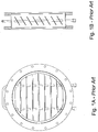
- Still another type of multi-vane valve is a fixed-positioned vane valve sold under the trademark "Temescal” by Ferrotec (USA) Corporation as part number 0627-0624-0.
- This multi-vane valve is not truly a valve since all of the vanes are in a fixed position in the range of 30-45 degrees, which are in fluid communication with cryogenic pumps.
- the vanes are each brazed to a stainless steel tube that is transverse to all of the vanes.
- the vanes act as a heat shield as well as to transfer heat to the stainless steel tube that contains cooling water flowing through the tube.
- Figures 1A and 1B illustrates an example of such a fixed, multi-vane valve showing a front view and a cross-sectional side view of the structural relationship of the cooling tube and the plurality of fixed vanes.
- Vacuum processing systems generally have a processing chamber of the type typically used for fabrication of computer chips and a vacuum pump, which is used to evacuate the processing chamber.
- High-vacuum pumps typically operate at pressures below those for plasma processing.
- All multi-vane valves attempt to provide greater control of the processing environment and to protect the high-vacuum pumps from heat and debris from the processing chamber.
- Multi-vane valves work by throttling the gas in the process chamber to create a differential pressure across the valve allowing the vacuum pump to operate at high vacuum levels while maintaining correct process pressures in the chamber.
- Multi-vane throttle valves having rotatable vanes provide greater control of the correct process pressures in the chamber by providing linear control over the full range of operation of the multi-vane valve.
- the disadvantage of the multi-vane throttle valves of the prior art is their limited capacity to shield the high vacuum pump from heat and/or debris.
- the present invention achieves this objective by providing an apparatus and a method according to the independent claims. Preferable embodiments are set-forth in the dependent claims.
- a multi-vane throttle valve for a vacuum process chamber includes a throttle chamber body having an inside exposed to the vacuum process chamber and an outside exposed to atmospheric pressure, the chamber body defining a through-opening for controlling vacuum within the vacuum process chamber, a plurality of rotatable vanes mounted within the through-opening for controlling a flow of gases through the through-opening where each rotatable vane includes a cooling fluid pathway in fluid communication with and disposed longitudinally along each rotatable vane, and a drive mechanism disposed on and connected to an outside of the throttle chamber body for rotating the plurality of rotatable vanes to vary the flow of process gases.
- the cooling fluid pathway is a cooling conduit disposed longitudinally along the rotatable vane.
- the cooling conduit is selected from the group consisting of a straight conduit, a sinusoidal conduit, a square-wave shaped conduit, a pair of longitudinal conduits with a transverse conduit connecting the pair of longitudinal conduits on one end, a pair of concentric conduits defining a flow path between an inner conduit and an outer conduit, and a longitudinal heat pipe.
- each of the plurality of rotatable vanes are interconnected in series forming a single, continuous flow path.
- the drive mechanism includes an actuator arm, a rotating arm fixedly connected to each rotatable vane, and a linking arm pivotally connecting a rotating arm of one rotatable vane with a rotating arm of an adjacent rotatable vane in series where one linking arm connects to the actuator arm.
- the rotating arm is connected on one end to the rotatable vane and on the other end to the linking arm
- the throttling valve includes a debris shield attached to each of the plurality of rotatable vanes.
- the throttle chamber body includes a first body flange, a second body flange and a vane chamber housing connected between the first body flange and the second body flange where the vane chamber housing contains the plurality of rotatable vanes.
- the vane chamber housing includes a top plate, a bottom plate, a first chamber side wall, a second chamber side wall, and a vane support feedthrough attached to the first chamber side wall that supports the cooling fluid pathway of a rotatable vane and maintains the pressure differential between the vacuum chamber process and the atmospheric pressure.
- the throttle valve includes a vacuum feedthrough supporting each of the plurality of rotatable vanes between the vacuum chamber process inside and the atmospheric pressure outside of the throttling valve.
- the multi-vane throttle valve includes a magnetic fluid vacuum feedthrough supporting each of the rotating vanes on one end between the inside and the outside of the throttle chamber body.
- the multi-vane throttle valve includes a rotary adapter connected to one end of each rotating vane for transporting cooling fluid between each rotating vane.
- the throttle valve when the cooling conduit is a heat pipe, the throttle valve further includes a cooling block for rotatably receiving one end portion of the heat pipe that is outside of the vane chamber housing.
- the cooling block may optionally be a liquid flow block or a thermoelectric module block or a combination thereof.
- the rotating vane includes a cooling conduit extending laterally along the longitudinal center line of the rotating vane and into a rotating joint that transports cooling fluid between each rotating vane.
- the rotating vane in another embodiment, includes a cooling conduit having a pair of concentric tubes extending laterally along the longitudinal center line of the rotating vane and into a rotating joint that transports cooling fluid between each rotating vane.
- the rotating vane includes a first cooling conduit disposed on the vane to one side of the longitudinal center line of the rotating vane and a second cooling conduit disposed on the vane to an opposite side of the longitudinal center line of the rotating vane.
- the first cooling conduit is in fluid communication with the second cooling conduit and both cooling conduits are in fluid communication with a rotating joint that transports cooling fluid between each rotating vane.
- the rotating vane includes a debris shield disposed onto one side of the rotating vane.
- the valve includes a coolant selected from water, cryogenic material and the like.
- Figs. 2-17 The preferred embodiment of the present invention is illustrated in Figs. 2-17 .
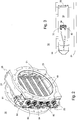
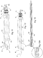
- FIG. 2 illustrates one embodiment of a multi-vane throttle valve 10 of the present invention.
- Throttle valve 10 includes a throttle chamber body 20, a plurality of rotatable vanes 40, and a drive mechanism 80.
- Throttle chamber body 20 has a vane chamber housing 20a, an inside surface 21 and an outside surface 22 that defines a through-opening 23 in which are disposed the plurality of rotatable vanes 40.
- Drive mechanism 80 is disposed on and connected to an outside 22 of the throttling chamber body 20 for moving the plurality of rotatable vanes 40 to vary the flow of process gases.
- Drive mechanism 80 has a drive motor 81 with an actuator arm 82 connected to a releasable linking arm 83 that is releasably and rotatably connected to a rotating arm 84.
- a fluid conduit 85 is interconnected with each of the plurality of rotatable vanes 40.
- FIG. 3 is a bottom view of multi-vane throttle valve 10. From this view, it can be seen that this embodiment of throttle chamber body 20 includes a first body flange 24 that is the vacuum pump side and a second body flange 26 that is the process chamber side. Between first body flange 24 and second body flange 26 is through-opening 23, which includes a vane chamber 28 in which is mounted the plurality of rotatable vanes 40. Vane chamber 28 has a bottom plate 30 on which is mounted a cooling fluid inlet port 32 and a cooling fluid outlet port 33 mounted to a cooling fluid manifold 34.
- Fig. 4 there is shown an exploded view of the embodiment of multi-vane throttle valve 10 illustrated in Fig. 1 .
- throttle chamber body 20 has through-opening 23 showing vane chamber 28 adjacent second body flange 26.
- Vane chamber 28 has a first chamber side wall 28a with a plurality of equally-spaced openings 29 in which each opening 29 are mounted a vacuum seal feedthrough 70.
- Each vacuum seal feedthrough 70 receives therethrough one end 41 of one of the plurality of rotatable vanes 40.
- Vacuum seal feedthroughs 70 rotatably support vanes 40.
- Each of the plurality of rotatable vanes 40 are rotatably supported on an opposite end 42 by a bearing 35 mounted on second side wall plate 36.
- Second side wall plate 36 is sealingly but removably attached to second side wall 28b with a plurality of bolts 36a to facility access to vane chamber 28 for maintenance and repair when required.
- each vane 40 has an optional debris shield 43 attached to one side of vane 40 that is facing the process chamber. Debris shields 43 are preferably used when vane 40 is fabricated from copper. When vane 40 is fabricated from stainless steel, no debris shields are necessary.
- the process chamber is typically used for chemical vapor deposition
- debris which includes the various chemicals that are used for coating targets within the process chamber is more easily removed from stainless steel than from copper.
- the rotatable vanes 40 also prevent the debris from reaching the vacuum pump, which is more costly to repair so preventing debris from entering the vacuum pump is one important aspect of the present invention.
- Another important aspect is the heat involved during the process being undertaken in the process chamber. Because the vacuum pump is typically continuously operating during a process, heated gases involved in the process within the process chamber are evacuated through the vacuum pump. The heat from the gases also causes damage to the vacuum pump. Even though the plurality of vanes 40 when in a completely closed position helps reduce this effect, it is not a practical solution since the purpose of the throttling vanes 40 is to better control the vacuum process, closing them completely is counter-productive.
- the plurality of vanes 40 in the present invention include a cooling conduit 44 that is disposed in and longitudinally extends along the length of each of the plurality of vanes 40.
- An external cooling liquid flows through cooling conduit 44 in order to remove the heat absorbed from the gas that is being evacuated by the vacuum pump through-opening 23 of multi-vane throttle valve 10.
- Cooling conduit 44 is in fluid communication with fluid conduit 85 which includes a plurality of rotary joints 87.
- An optional drive mechanism cover 110 may be mounted over drive mechanism 80 and rotary joints 87 to enclose and protect actuator arm 82, linking arms 83 and rotary arms 84.
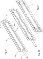
- vane 40 has a proximal vane end 45 and a distal vane end 46.
- Distal vane end 46 has a distal support 47 configured to connect distal vane end 46 to a mating support component in second side wall plate 36 of throttle chamber body 20 in a rotatable relationship.
- Proximal vane end 45 has a proximal support 48 configured to connect proximal vane end 45 to a matting support component in first chamber side wall 28a of throttle chamber body 20 in a rotatable relationship.
- Vane 40 has a first cooling conduit 44a that extends longitudinally through one half of vane 40 and a second cooling conduit 44b that extends longitudinally though the other half of vane 40.
- a connecting cooling conduit 44c (shown in Fig. 7 ) communicates transversely with first cooling conduit 44a and second cooling conduit 44b adjacent distal vane end 46 to create a continuous cooling conduit 44.
- the cooling conduit may have other configurations such as straight conduit, a sinusoidal conduit, a square-wave shaped conduit, a pair of longitudinal conduits with a transverse conduit connecting the pair of longitudinal conduits on one end, a pair of concentric conduits defining a flow path between an inner conduit and an outer conduit, and a longitudinal heat pipe.
- Fig. 5A illustrates a vane with a pair of square-wave, cooling conduits.
- FIG. 6 illustrates a perspective view of optional debris shield 43.
- Debris shield 43 attaches to one side of vane 40, preferably the side that is exposed to the process chamber in order to prevent damaging material from the process chamber from entering into the vacuum pump.
- Debris shield 43 may be attached to vane 40 using any known methods including, but not limited to, brazing, using mechanical fasteners, attaching components to allow the shield to snap fit onto vane 40, and the like.
- Debris shield 43 is preferably made of stainless steel but may be made of any metal and/or non-metal material capable of protecting vanes 40 and maintaining the shields integrity during one or more vacuum chamber processes.
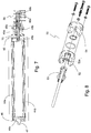
- FIG. 7 is a side, partial cross-sectional view of the embodiment of vane 40 shown in Fig. 5 with a coolant supply and coolant return member.
- this embodiment of vane 40 includes a proximal vane end 45 and a distal vane end 46.
- Distal vane end 46 has a distal support 47 while proximal vane end 45 has proximal support 48.
- Vane 40 has a first cooling conduit 44a that extends longitudinally along or through one half of vane 40 and a second cooling conduit 44b that extends longitudinally along or though the other half of vane 40.
- a connecting cooling conduit 44c communicates transversely with first cooling conduit 44a and second cooling conduit 44b adjacent distal vane end 46 to create a continuous cooling conduit 44.
- proximal support 48 is configured as a pair of concentric tubes 49a (outer tube), 49b (inner tube) forming an outer conduit chamber 48a and an inner conduit chamber 48b where the outer conduit chamber 48a fluidly communicates with first cooling conduit 44a and inner conduit chamber 48b fluidly communicates with second cooling conduit 44b.
- Inner and outer conduit chambers 48a, 48b extend into a rotary adapter 50 that where each of the inner and outer conduit chambers 48a, 48b communicates with a coolant supply port 60a and a return port 60b, respectively.
- FIG. 8 shows an exploded, perspective view of rotary adapter 50 illustrated in Fig. 7 .
- adapter 50 includes a first rotary housing 52 and a second rotary housing 54 axially aligned with and secured to first rotary housing 52.
- Adapter 50 also includes a hollow shaft 53 that is axially disposed within first rotary housing 52 and is configured to receive inner tube 49b through hollow shaft 53 and into second rotary housing 54.
- a space 52a is formed between a portion of the outside surface of hollow rotary shaft 53 and the inside wall of first rotary housing 52, which space 52a fluidly communicates with outer conduit chamber 48a of proximal support 48.
- coolant supply port 60a is physically connected to first rotary housing 52 and coolant return supply port 60b is physically connected to second rotary housing 54.
- This embodiment provides coolant into and out of vane 40 through proximal vane end 45.
- FIG. 9 is a perspective, partial cross-sectional view of another embodiment of rotary adapter 50.
- rotary adapter 50 includes only a single rotary housing 56 and a modified rotary shaft 57.
- Rotary housing 56 provides the same function as first rotary housing 52 with coolant supply port 60a.
- Rotary shaft 57 is extended through rotary housing 56 and terminated with coolant return port 60b. This embodiment reduces the number of parts required for rotary adapter 50 making assembly and maintenance easier as well as reducing the cost of rotary adapter 50 while providing the same function.
- FIG. 10 is an enlarged, cross-sectional view of rotary valve 50 and proximal support 48 showing the fluid flow for cooling vanes 40.
- outer tube 49a of proximal support 48 is rotatably supported by a feedthrough support 70, which is secured to first chamber side wall 28a and inner tube 49b extends beyond feedthrough support 70 and into rotary valve 50.
- Arrows 150 indicate the flow of coolant into a vane 40 and arrows 160 indicate the flow of coolant out of vane 40. Notwithstanding the description provided above about rotary valve 50 illustrated in Fig.
- FIG. 11 there is illustrated a side view of a vane 40 with rotary valve 50 illustrated and described in Fig. 9 .
- this embodiment of vane 40 includes proximal vane end 45 with proximal support 48 and distal vane end 46 with distal support 47.
- Vane 40 has first cooling conduit 44a that extends longitudinally through one half of vane 40 and second cooling conduit 44b that extends longitudinally though the other half of vane 40.
- Connecting cooling conduit 44c communicates transversely with first cooling conduit 44a and second cooling conduit 44b adjacent distal vane end 46 to create continuous cooling conduit 44.
- rotary adapter 50 includes only single rotary housing 56 and modified rotary shaft 57.
- Rotary housing 56 provides the same function as first rotary housing 52 with coolant supply port 60a.
- Rotary shaft 57 fluidly communicates through rotary housing 56 and with coolant return port 60b.
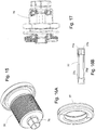
- FIG 12 illustrates another embodiment of vane 40.
- vane 40 has a single, coolant conduit 44 that is extends longitudinally along the longitudinal central axis of vane 40 from proximal support 48 to distal support 47.
- Proximal support 48 is rotatably supported by feedthrough 70 and includes a single feedthrough collar 72. Because feedthrough 70 rotatably supports proximal vane support 48, coolant supply port 60a may be fixedly attached to feedthrough collar 72 where proximal support 48 is a single tube and not a pair of concentric tubes.
- coolant conduit 44 is a single tube that extends along the longitudinal central axis of vane 40, then the fluid coolant must enter one end of vane 40 (i.e.
- distal support 47 must also include similar feedthrough 70 and feedthrough collar 72 to which coolant return port 60b is attached. As explained above, where two or more vanes 40 are incorporated within throttle valve 10, the assignment of coolant supply port 60a and coolant return port 60b to the feedthrough collars 72 at proximal vane end 45 and distal vane end 46 will alternate accordingly in order to form a continuous coolant circuit through vanes 40.
- FIG. 13 illustrates another embodiment of coolant conduit 44 of vane 40 (not shown) where cooling fluid, i.e. coolant, enters and exits from the same end (i.e. proximal vane end 45) of vane 40.
- coolant conduit 44 is a pair of concentric tubes 44d (outer tube) and 44e (inner tube) that extends along the longitudinal central axis of vane 40 creating an outer conduit chamber 44f and an inner conduit chamber 44g. Coolant fluid enters one of the conduit chambers and exits through the other of the conduit chambers.
- Fig. 13A illustrates an enlarged view of coolant conduit 44 at distal vane end 46. Arrows 200 indicate the flow of coolant along the inside of coolant conduit 44.
- a rotary valve 50 along with feedthrough 70 supports proximal support 48 formed by coolant conduit 40 at proximal vane end 45.
- proximal support 48 formed by coolant conduit 40 at proximal vane end 45.
- FIG 14 illustrates another embodiment of vane 40 with a cooling conduit.
- the cooling system of vane 40 includes a heat pipe 130 disposed along the longitudinal central axis of vane 40 that has a heat pipe proximal end 132 and a heat pipe distal end 150.
- Heat pipe distal end 150 is rotatably supported by a bearing 152 disposed in a bearing housing 154 attached to second side wall 36 of throttle housing body 22.
- Heat pipe proximal end 132 is rotatably supported by feedthrough 70 and extends outside of throttle housing body 22 into a rotary adapter 50.
- An end portion 132a of heat pipe proximal end 132 is rotatably held within rotary adapter 50.
- Rotary adapter 50 may be a coolant block having a rotary housing 56 forming an adapter chamber 56a, coolant supply port 60a and a coolant return port 60b in fluid communication with adapter chamber 56a.
- a coolant block may be incorporated as part of rotary adapter 50, which would provide the cooling mechanism for cooling heat pipe proximal end 132.
- Heat pipe 130 and the thermoelectric module have the typical operating and structural characteristics of those components and are well known to those of ordinary skill in the respective arts so no explanation or discussion of their operation is required.
- Feedthrough 70 has a feedthrough flange 74 and securing nut 75 for attaching feedthrough 70 to a side wall of vane chamber 28.
- Feedthrough 70 also includes a hollow shaft 76 for receiving and supporting the end of vane 40. Hollow shaft 76 rotated within feedthrough 70 and maintains a seal between the inside of throttle vane valve, which is at a reduced pressure, and the outside of throttle vane valve, which is at atmospheric pressure.
- FIGs 16A and 16B illustrate one embodiment of a sealing structure of feedthrough 70 used to rotatably support proximal support 48 and, in the case where a single coolant conduit is disposed along the longitudinal central axis of vane 40, and distal support 47.
- feedthrough 70 incorporates a quad O-ring 77 seal to isolate the vacuum inside the throttle valve body 22 and the atmosphere outside of throttle valve body 22.
- Quad O-ring 77 incorporates two sealing surfaces 77a, 77b on the outer periphery of the O-ring and two sealing surfaces 77c, 77d on the inner periphery of the O-ring.
- the quad O-ring 77 provides increased reliability over standard O-rings.
- FIG 17 illustrates a side view of a preferred embodiment of feedthrough 70.
- feedthrough 70 incorporates a magnetic fluid seal and associated components for forming such a seal.
- the preferred magnetic fluid feedthrough 70 is available from Ferrotec (USA) Corporation, Bedford, NH under custom product no. HS-500-SFBSC.
Landscapes
- Engineering & Computer Science (AREA)
- General Engineering & Computer Science (AREA)
- Mechanical Engineering (AREA)
- Physics & Mathematics (AREA)
- Thermal Sciences (AREA)
- Details Of Valves (AREA)
- Lift Valve (AREA)
- Valve Housings (AREA)
Applications Claiming Priority (3)
| Application Number | Priority Date | Filing Date | Title |
|---|---|---|---|
| US201161509765P | 2011-07-20 | 2011-07-20 | |
| US13/549,771 US8833383B2 (en) | 2011-07-20 | 2012-07-16 | Multi-vane throttle valve |
| PCT/US2012/047102 WO2013012880A1 (en) | 2011-07-20 | 2012-07-18 | Multi-vane throttle valve |
Publications (3)
| Publication Number | Publication Date |
|---|---|
| EP2734758A1 EP2734758A1 (en) | 2014-05-28 |
| EP2734758A4 EP2734758A4 (en) | 2015-03-25 |
| EP2734758B1 true EP2734758B1 (en) | 2016-05-04 |
Family
ID=47554927
Family Applications (1)
| Application Number | Title | Priority Date | Filing Date |
|---|---|---|---|
| EP12814127.2A Active EP2734758B1 (en) | 2011-07-20 | 2012-07-18 | Multi-vane throttle valve |
Country Status (9)
| Country | Link |
|---|---|
| US (1) | US8833383B2 (enExample) |
| EP (1) | EP2734758B1 (enExample) |
| JP (1) | JP5961260B2 (enExample) |
| KR (1) | KR101981037B1 (enExample) |
| ES (1) | ES2574264T3 (enExample) |
| IL (1) | IL230508B (enExample) |
| MX (1) | MX339089B (enExample) |
| MY (1) | MY165705A (enExample) |
| WO (1) | WO2013012880A1 (enExample) |
Families Citing this family (4)
| Publication number | Priority date | Publication date | Assignee | Title |
|---|---|---|---|---|
| WO2016024971A1 (en) * | 2014-08-14 | 2016-02-18 | Ferrotec (Usa) Corporation | Multi-vane throttle valve |
| US20160097351A1 (en) * | 2014-10-07 | 2016-04-07 | Borgwarner Inc. | Swirl type lp - egr throttle mechanism |
| TW201636525A (zh) | 2015-01-16 | 2016-10-16 | Mks儀器公司 | 徑向密封蝶形閥 |
| CN115234662B (zh) * | 2022-06-10 | 2025-06-06 | 浙江创享阀门科技有限公司 | 冶炼化工烟道防抱死多功能蝶阀 |
Family Cites Families (107)
| Publication number | Priority date | Publication date | Assignee | Title |
|---|---|---|---|---|
| DE1110801B (de) * | 1959-10-06 | 1961-07-13 | Maschf Augsburg Nuernberg Ag | Gekuehlte Rauchgasklappe |
| US3833018A (en) | 1973-02-21 | 1974-09-03 | Pass Port Syst Corp | Low leakage vacuum valve and chamber using same |
| DE2551429B2 (de) | 1975-11-15 | 1978-03-02 | Vat Ag Fuer Vakuum-Apparate-Technik, Haag (Schweiz) | Aus Metall bestehende Dichtvorrichtung an einem Vakuumverschluß |
| JPS52143028U (enExample) * | 1976-04-23 | 1977-10-29 | ||
| JPS52156329U (enExample) * | 1976-05-22 | 1977-11-28 | ||
| JPS567742Y2 (enExample) * | 1977-04-05 | 1981-02-20 | ||
| US4169488A (en) * | 1977-11-23 | 1979-10-02 | Caterpillar Tractor Co. | Cooled engine valve |
| US4175582A (en) * | 1978-04-11 | 1979-11-27 | Foster Wheeler Energy Corporation | Isolating/pressure relief damper |
| US4353388A (en) * | 1979-07-12 | 1982-10-12 | Kubota, Ltd. | Butterfly valve |
| JPS5625880U (enExample) * | 1979-08-07 | 1981-03-10 | ||
| JPS56132440U (enExample) * | 1980-03-10 | 1981-10-07 | ||
| JPS6028660U (ja) * | 1983-08-03 | 1985-02-26 | 株式会社クボタ | 高温流体用流量調節弁 |
| JPS6058990U (ja) * | 1983-09-28 | 1985-04-24 | 新日本製鐵株式会社 | ホ−ス用回転継手 |
| US4610197A (en) * | 1985-06-12 | 1986-09-09 | Philips Industrial Components, Inc. | Damper blade construction |
| US4785851A (en) | 1987-07-20 | 1988-11-22 | Mks Instruments Inc. | Vacuum security valve having a buffer volume |
| US4800915A (en) * | 1987-08-14 | 1989-01-31 | S. P. Kinney Engineers, Inc. | Butterfly valve |
| US5120019A (en) | 1989-08-03 | 1992-06-09 | Brooks Automation, Inc. | Valve |
| US5100100A (en) | 1990-09-12 | 1992-03-31 | Mks Instruments, Inc. | Fluid control and shut off valve |
| US5318272A (en) | 1992-06-12 | 1994-06-07 | Mks Instruments, Inc. | Motor controlled throttling poppet valve |
| JP2758535B2 (ja) | 1992-07-16 | 1998-05-28 | 株式会社日立製作所 | 電子スロットル制御装置 |
| US5314164A (en) | 1992-07-17 | 1994-05-24 | Mks Instruments, Inc. | Pivotal diaphragm, flow control valve |
| JPH07190203A (ja) * | 1993-12-27 | 1995-07-28 | Fuji Inbatsuku Kk | スロットルバルブ |
| DE4401215C1 (de) | 1994-01-18 | 1995-03-23 | Vat Holding Ag | Eckventil |
| US5485542A (en) | 1994-07-18 | 1996-01-16 | Mks Instruments, Inc. | Heated fluid control valve with electric heating element and thermocouple wiring disposed in rotatable shaft |
| JP3305515B2 (ja) | 1994-10-06 | 2002-07-22 | 日本エム・ケー・エス株式会社 | 流量制御弁 |
| DE4446947C2 (de) | 1994-12-28 | 2003-04-10 | Vat Holding Ag Haag | Ringförmiger Dichtkörper |
| JP3322772B2 (ja) | 1995-05-22 | 2002-09-09 | 日本エム・ケー・エス株式会社 | 制御弁 |
| SE509391C2 (sv) * | 1995-07-06 | 1999-01-18 | Abb Carbon Ab | Axelanordning för en ventil |
| US5706851A (en) * | 1995-11-27 | 1998-01-13 | Hyisa S.A. De C.V. | Plug valve |
| US5765592A (en) * | 1996-02-14 | 1998-06-16 | The Boc Group, Inc. | Valve |
| JP3377077B2 (ja) | 1997-04-22 | 2003-02-17 | 日本エム・ケー・エス株式会社 | 弁体及びそれを用いた電磁制御弁 |
| DE19919426C1 (de) * | 1999-04-28 | 2000-03-30 | Siemens Ag | Ventilaufnahmevorrichtung für ein Dosierventil einer Abgasnachbehandlungsanlage |
| US6161576A (en) | 1999-06-23 | 2000-12-19 | Mks Instruments, Inc. | Integrated turbo pump and control valve system |
| US6089537A (en) | 1999-06-23 | 2000-07-18 | Mks Instruments, Inc. | Pendulum valve assembly |
| WO2001004522A1 (en) | 1999-07-09 | 2001-01-18 | Arthur Brenes | Throttle gate valve |
| US6367770B1 (en) | 2000-03-23 | 2002-04-09 | Vat Holding Ag | Vacuum valve for separating two vacuum chambers |
| US6328051B1 (en) | 2000-06-28 | 2001-12-11 | Mks Instruments, Inc. | Dual pendulum valve assembly |
| US6409149B1 (en) | 2000-06-28 | 2002-06-25 | Mks Instruments, Inc. | Dual pendulum valve assembly with valve seat cover |
| US6505812B1 (en) | 2000-11-17 | 2003-01-14 | Mks Instruments, Inc. | Solenoid valve |
| US6439255B1 (en) | 2000-11-17 | 2002-08-27 | Mks Instruments, Inc. | Valve flapper with dynamic circumference seal |
| US6416037B1 (en) | 2001-01-11 | 2002-07-09 | Vat Holding Ag | Vacuum pipe |
| US6431518B1 (en) | 2001-01-11 | 2002-08-13 | Vat Holding Ag | Vacuum valve |
| US6629682B2 (en) | 2001-01-11 | 2003-10-07 | Vat Holding Ag | Vacuum valve |
| US6471181B2 (en) | 2001-01-11 | 2002-10-29 | Vat Holding Ag | Suspension of a valve plate of a vacuum valve |
| US6427969B1 (en) | 2001-04-27 | 2002-08-06 | Helix Technology Inc. | Adjustable gate valve assembly for vacuum chamber |
| US6494434B1 (en) | 2001-07-12 | 2002-12-17 | Vat Holding Ag | Butterfly valve |
| US7127901B2 (en) | 2001-07-20 | 2006-10-31 | Brooks Automation, Inc. | Helium management control system |
| US6609697B2 (en) | 2001-09-06 | 2003-08-26 | Robert Andreas Gsteu | Vacuum control valve |
| JP3833096B2 (ja) | 2001-10-17 | 2006-10-11 | 新明和工業株式会社 | 真空ゲート弁 |
| US6685163B2 (en) | 2002-02-26 | 2004-02-03 | Vat Holding Ag | Vacuum valve |
| US6698719B2 (en) | 2002-06-26 | 2004-03-02 | Vat Holding Ag | Seal arrangement for a vacuum valve |
| JP2004183678A (ja) | 2002-11-29 | 2004-07-02 | Nippon M K S Kk | 電磁バルブ |
| US6776394B2 (en) | 2002-12-30 | 2004-08-17 | Mks Instruments, Inc. | Pendulum valve assembly |
| US6863256B2 (en) | 2003-02-20 | 2005-03-08 | Mks Instruments, Inc. | Seal ring for pendulum valve assembly |
| US20040246649A1 (en) | 2003-06-03 | 2004-12-09 | Mks Instruments, Inc. | Flow control valve with magnetic field sensor |
| US6994311B2 (en) | 2003-06-27 | 2006-02-07 | Vat Holding Ag | Regulating vacuum valve |
| US20060192345A1 (en) * | 2003-07-07 | 2006-08-31 | Zhixin Li | Magnetic Fluidic Seal with Improved Pressure Capacity |
| US6994317B2 (en) | 2003-09-19 | 2006-02-07 | Vat Holding Ag | Regulating vacuum valve |
| US7032882B2 (en) | 2003-09-29 | 2006-04-25 | Mks Instruments, Inc. | Valve assembly having novel flow characteristics |
| US7090192B2 (en) | 2003-10-21 | 2006-08-15 | Vay Holding Ag | Vacuum valve |
| JP2005140223A (ja) | 2003-11-06 | 2005-06-02 | Nippon M K S Kk | 制御弁 |
| KR100960030B1 (ko) | 2004-03-12 | 2010-05-28 | 배트 홀딩 아게 | 진공 게이트 밸브 |
| US7194867B2 (en) | 2004-03-19 | 2007-03-27 | Brooks Automation, Inc. | Integrated rough/purge/vent (RPV) valve |
| US7073771B2 (en) | 2004-03-30 | 2006-07-11 | Mks Instruments, Inc. | Porous valve assembly |
| JP4541015B2 (ja) | 2004-03-31 | 2010-09-08 | ヴィ・エイ・ティー ホールディング アクチェンゲゼルシャフト | 真空ゲートバルブ、バルブ板および多機能工具 |
| US7628860B2 (en) | 2004-04-12 | 2009-12-08 | Mks Instruments, Inc. | Pulsed mass flow delivery system and method |
| US7036794B2 (en) | 2004-08-13 | 2006-05-02 | Vat Holding Ag | Method for control of a vacuum valve arranged between two vacuum chambers |
| US7011294B1 (en) | 2004-09-08 | 2006-03-14 | Vat Holding Ag | Vacuum valve |
| CN101084409B (zh) | 2004-10-07 | 2011-03-23 | 布鲁克斯自动化有限公司 | 用于制冷过程的高效热交换器 |
| US7387135B2 (en) | 2004-12-23 | 2008-06-17 | Mks Instruments, Inc. | Valve assembly having rigid seating surfaces |
| DE102005004987B8 (de) | 2005-02-02 | 2017-12-14 | Vat Holding Ag | Vakuumventil |
| US7278444B2 (en) | 2005-02-22 | 2007-10-09 | Mks Instruments, Inc. | Valve assembly having improved pump-down performance |
| US7428913B2 (en) | 2005-04-26 | 2008-09-30 | Mks Instruments, Inc. | Valve assembly having articulating rigid seating surface |
| US20070007475A1 (en) | 2005-07-07 | 2007-01-11 | Peter Zvokelj | Vacuum valve |
| US7802772B2 (en) | 2005-12-20 | 2010-09-28 | Vat Holding Ag | Pendulum and slide gate vacuum valve |
| KR101323311B1 (ko) | 2005-12-20 | 2013-10-30 | 배트 홀딩 아게 | 유로를 가스 기밀하게 폐쇄하는 밸브 |
| US7396001B2 (en) | 2005-12-20 | 2008-07-08 | Vat Holding Ag | Valve for essentially gastight closing a flow path |
| US7643909B2 (en) | 2006-03-30 | 2010-01-05 | Mks Instruments, Inc. | Highly responsive master-slave valve positioning |
| JP4979429B2 (ja) | 2006-03-31 | 2012-07-18 | バット ホールディング アーゲー | 真空バルブ |
| US7500649B2 (en) | 2006-05-05 | 2009-03-10 | Vat Holding Ag | Vacuum valve drive |
| TWI388754B (zh) | 2006-06-16 | 2013-03-11 | Vat Holding Ag | 真空閥 |
| CH699258B1 (de) | 2006-07-11 | 2010-02-15 | Vat Holding Ag | Vakuumventil und Verschlussteller |
| JP2008025835A (ja) | 2006-07-18 | 2008-02-07 | Vat Holding Ag | 真空弁、及び連結棒に取り付け可能な閉鎖ディスク |
| DE102007030006B4 (de) | 2006-07-19 | 2009-12-17 | Vat Holding Ag | Vakuumventil |
| JP5080169B2 (ja) | 2006-09-20 | 2012-11-21 | バット ホールディング アーゲー | 真空バルブ |
| WO2008144670A1 (en) | 2007-05-18 | 2008-11-27 | Brooks Automation, Inc. | Load lock fast pump vent |
| JP5324827B2 (ja) | 2007-06-08 | 2013-10-23 | ヴィ・エイ・ティー ホールディング アクチェンゲゼルシャフト | 脚部要素を有する真空ゲートバルブ |
| DE102007034926A1 (de) | 2007-07-24 | 2009-02-05 | Vat Holding Ag | Verfahren zur Steuerung oder Regelung eines Vakuumventils |
| DE102007034927A1 (de) | 2007-07-24 | 2009-02-05 | Vat Holding Ag | Verfahren zur Steuerung oder Regelung eines Vakuumventils |
| US7731151B2 (en) * | 2007-09-27 | 2010-06-08 | Kenneth K L Lee | Pendulum vacuum gate valve |
| DE102007048252A1 (de) | 2007-10-08 | 2009-04-09 | Vat Holding Ag | Vakuumventildichtungswerkstoff auf Basis von peroxidhärtbaren Fluorkautschuk-Compounds |
| CH700247B1 (de) | 2007-10-10 | 2010-07-30 | Vat Holding Ag | Vakuumventil mit Dichtungsträgereinsatz. |
| CH700327B1 (de) | 2007-10-22 | 2010-08-13 | Vat Holding Ag | Vakuumventil mit Nut und Dichtring. |
| DE102007059039A1 (de) | 2007-12-06 | 2009-06-18 | Vat Holding Ag | Vakuumventil |
| US8386083B2 (en) | 2008-06-16 | 2013-02-26 | Mks Instruments, Inc. | Systems and methods for updating valve cracking current in mass flow controllers |
| US7950294B2 (en) | 2008-06-20 | 2011-05-31 | Mks Instruments, Inc. | Preventive maintenance diagnostics for valve systems |
| EP2146122A1 (de) | 2008-07-18 | 2010-01-20 | VAT Holding AG | Vakuumventil und Verschlussteller für ein Vakuumventil |
| KR20110057198A (ko) | 2008-09-05 | 2011-05-31 | 배트 홀딩 아게 | 기밀 샤프트 이동관통부를 구비하는 진공밸브 |
| DE102008049353A1 (de) | 2008-09-29 | 2010-04-08 | Vat Holding Ag | Vakuumventil |
| DE102008051349B3 (de) | 2008-10-15 | 2009-11-12 | Vat Holding Ag | Vakuumventil |
| EP2224153A1 (de) | 2009-02-25 | 2010-09-01 | VAT Holding AG | Vakuumdoppelschieberventil |
| WO2010115917A1 (de) | 2009-04-07 | 2010-10-14 | Vat Holding Ag | Vakuumventil und vakuumkammersystem |
| TWI541465B (zh) | 2009-10-27 | 2016-07-11 | Vat控股股份有限公司 | 用於真空閥之封閉單元 |
| WO2011072315A1 (de) | 2009-12-14 | 2011-06-23 | Vat Holding Ag | Vakuumventil |
| DE102010053411B4 (de) | 2009-12-15 | 2023-07-06 | Vat Holding Ag | Vakuumventil |
| EP2336611A1 (en) | 2009-12-15 | 2011-06-22 | Applied Materials, Inc. | Water cooled valve |
| US8657256B2 (en) | 2010-01-25 | 2014-02-25 | Vat Holding Ag | Vacuum valve |
-
2012
- 2012-07-16 US US13/549,771 patent/US8833383B2/en active Active
- 2012-07-18 ES ES12814127.2T patent/ES2574264T3/es active Active
- 2012-07-18 EP EP12814127.2A patent/EP2734758B1/en active Active
- 2012-07-18 MY MYPI2014000066A patent/MY165705A/en unknown
- 2012-07-18 MX MX2014000269A patent/MX339089B/es active IP Right Grant
- 2012-07-18 KR KR1020147001334A patent/KR101981037B1/ko active Active
- 2012-07-18 JP JP2014521720A patent/JP5961260B2/ja active Active
- 2012-07-18 WO PCT/US2012/047102 patent/WO2013012880A1/en not_active Ceased
-
2014
- 2014-01-16 IL IL230508A patent/IL230508B/en active IP Right Grant
Also Published As
| Publication number | Publication date |
|---|---|
| IL230508A0 (en) | 2014-03-31 |
| CN103688092A (zh) | 2014-03-26 |
| MX339089B (es) | 2016-05-11 |
| JP5961260B2 (ja) | 2016-08-02 |
| IL230508B (en) | 2018-06-28 |
| EP2734758A1 (en) | 2014-05-28 |
| JP2014525016A (ja) | 2014-09-25 |
| EP2734758A4 (en) | 2015-03-25 |
| MY165705A (en) | 2018-04-20 |
| WO2013012880A1 (en) | 2013-01-24 |
| ES2574264T3 (es) | 2016-06-16 |
| KR20140045501A (ko) | 2014-04-16 |
| US20130019951A1 (en) | 2013-01-24 |
| KR101981037B1 (ko) | 2019-08-28 |
| MX2014000269A (es) | 2014-04-14 |
| US8833383B2 (en) | 2014-09-16 |
Similar Documents
| Publication | Publication Date | Title |
|---|---|---|
| EP1063456B1 (en) | Integrated turbo pump and control valve system | |
| EP2734758B1 (en) | Multi-vane throttle valve | |
| EP2336611A1 (en) | Water cooled valve | |
| EP0119451B1 (en) | Multiport cryopump | |
| TWI550220B (zh) | 流體控制閥 | |
| US9157533B2 (en) | Multi-vane throttle valve | |
| TW202134556A (zh) | 蝶閥 | |
| EP3180552B1 (en) | Multi-vane throttle valve | |
| US5762100A (en) | Head for coplanar meter body transmitter | |
| KR20020010680A (ko) | 진공 게이트 밸브 및 게이트 밸브를 구비한 진공 처리 장치 | |
| CN111194474A (zh) | 双端口远程等离子清洁隔离阀 | |
| US5338913A (en) | Electron beam gun with liquid cooled rotatable crucible | |
| US10969029B2 (en) | Low particle protected flapper valve | |
| CN103688092B (zh) | 多叶片节流阀 | |
| HK1235844A1 (en) | Multi-vane throttle valve | |
| KR102850015B1 (ko) | 개폐 기구 및 배기 전환 기구 및 기판 처리 장치 | |
| JPH0492169A (ja) | 開閉弁 |
Legal Events
| Date | Code | Title | Description |
|---|---|---|---|
| PUAI | Public reference made under article 153(3) epc to a published international application that has entered the european phase |
Free format text: ORIGINAL CODE: 0009012 |
|
| 17P | Request for examination filed |
Effective date: 20140110 |
|
| AK | Designated contracting states |
Kind code of ref document: A1 Designated state(s): AL AT BE BG CH CY CZ DE DK EE ES FI FR GB GR HR HU IE IS IT LI LT LU LV MC MK MT NL NO PL PT RO RS SE SI SK SM TR |
|
| DAX | Request for extension of the european patent (deleted) | ||
| REG | Reference to a national code |
Ref country code: DE Ref legal event code: R079 Ref document number: 602012018182 Country of ref document: DE Free format text: PREVIOUS MAIN CLASS: F16K0003040000 Ipc: F16K0051020000 |
|
| A4 | Supplementary search report drawn up and despatched |
Effective date: 20150219 |
|
| RIC1 | Information provided on ipc code assigned before grant |
Ipc: F16K 1/22 20060101ALI20150213BHEP Ipc: F16K 51/02 20060101AFI20150213BHEP Ipc: F16K 49/00 20060101ALI20150213BHEP |
|
| GRAP | Despatch of communication of intention to grant a patent |
Free format text: ORIGINAL CODE: EPIDOSNIGR1 |
|
| INTG | Intention to grant announced |
Effective date: 20151127 |
|
| GRAS | Grant fee paid |
Free format text: ORIGINAL CODE: EPIDOSNIGR3 |
|
| GRAA | (expected) grant |
Free format text: ORIGINAL CODE: 0009210 |
|
| AK | Designated contracting states |
Kind code of ref document: B1 Designated state(s): AL AT BE BG CH CY CZ DE DK EE ES FI FR GB GR HR HU IE IS IT LI LT LU LV MC MK MT NL NO PL PT RO RS SE SI SK SM TR |
|
| REG | Reference to a national code |
Ref country code: GB Ref legal event code: FG4D |
|
| REG | Reference to a national code |
Ref country code: CH Ref legal event code: EP |
|
| REG | Reference to a national code |
Ref country code: AT Ref legal event code: REF Ref document number: 797221 Country of ref document: AT Kind code of ref document: T Effective date: 20160515 |
|
| REG | Reference to a national code |
Ref country code: IE Ref legal event code: FG4D |
|
| REG | Reference to a national code |
Ref country code: NL Ref legal event code: FP |
|
| REG | Reference to a national code |
Ref country code: ES Ref legal event code: FG2A Ref document number: 2574264 Country of ref document: ES Kind code of ref document: T3 Effective date: 20160616 |
|
| REG | Reference to a national code |
Ref country code: SE Ref legal event code: TRGR |
|
| REG | Reference to a national code |
Ref country code: DE Ref legal event code: R096 Ref document number: 602012018182 Country of ref document: DE |
|
| REG | Reference to a national code |
Ref country code: FR Ref legal event code: PLFP Year of fee payment: 5 |
|
| REG | Reference to a national code |
Ref country code: LT Ref legal event code: MG4D |
|
| PG25 | Lapsed in a contracting state [announced via postgrant information from national office to epo] |
Ref country code: LT Free format text: LAPSE BECAUSE OF FAILURE TO SUBMIT A TRANSLATION OF THE DESCRIPTION OR TO PAY THE FEE WITHIN THE PRESCRIBED TIME-LIMIT Effective date: 20160504 Ref country code: FI Free format text: LAPSE BECAUSE OF FAILURE TO SUBMIT A TRANSLATION OF THE DESCRIPTION OR TO PAY THE FEE WITHIN THE PRESCRIBED TIME-LIMIT Effective date: 20160504 Ref country code: NO Free format text: LAPSE BECAUSE OF FAILURE TO SUBMIT A TRANSLATION OF THE DESCRIPTION OR TO PAY THE FEE WITHIN THE PRESCRIBED TIME-LIMIT Effective date: 20160804 |
|
| PG25 | Lapsed in a contracting state [announced via postgrant information from national office to epo] |
Ref country code: HR Free format text: LAPSE BECAUSE OF FAILURE TO SUBMIT A TRANSLATION OF THE DESCRIPTION OR TO PAY THE FEE WITHIN THE PRESCRIBED TIME-LIMIT Effective date: 20160504 Ref country code: GR Free format text: LAPSE BECAUSE OF FAILURE TO SUBMIT A TRANSLATION OF THE DESCRIPTION OR TO PAY THE FEE WITHIN THE PRESCRIBED TIME-LIMIT Effective date: 20160805 Ref country code: LV Free format text: LAPSE BECAUSE OF FAILURE TO SUBMIT A TRANSLATION OF THE DESCRIPTION OR TO PAY THE FEE WITHIN THE PRESCRIBED TIME-LIMIT Effective date: 20160504 Ref country code: RS Free format text: LAPSE BECAUSE OF FAILURE TO SUBMIT A TRANSLATION OF THE DESCRIPTION OR TO PAY THE FEE WITHIN THE PRESCRIBED TIME-LIMIT Effective date: 20160504 Ref country code: PT Free format text: LAPSE BECAUSE OF FAILURE TO SUBMIT A TRANSLATION OF THE DESCRIPTION OR TO PAY THE FEE WITHIN THE PRESCRIBED TIME-LIMIT Effective date: 20160905 |
|
| PG25 | Lapsed in a contracting state [announced via postgrant information from national office to epo] |
Ref country code: DK Free format text: LAPSE BECAUSE OF FAILURE TO SUBMIT A TRANSLATION OF THE DESCRIPTION OR TO PAY THE FEE WITHIN THE PRESCRIBED TIME-LIMIT Effective date: 20160504 Ref country code: SK Free format text: LAPSE BECAUSE OF FAILURE TO SUBMIT A TRANSLATION OF THE DESCRIPTION OR TO PAY THE FEE WITHIN THE PRESCRIBED TIME-LIMIT Effective date: 20160504 Ref country code: RO Free format text: LAPSE BECAUSE OF FAILURE TO SUBMIT A TRANSLATION OF THE DESCRIPTION OR TO PAY THE FEE WITHIN THE PRESCRIBED TIME-LIMIT Effective date: 20160504 Ref country code: CZ Free format text: LAPSE BECAUSE OF FAILURE TO SUBMIT A TRANSLATION OF THE DESCRIPTION OR TO PAY THE FEE WITHIN THE PRESCRIBED TIME-LIMIT Effective date: 20160504 Ref country code: EE Free format text: LAPSE BECAUSE OF FAILURE TO SUBMIT A TRANSLATION OF THE DESCRIPTION OR TO PAY THE FEE WITHIN THE PRESCRIBED TIME-LIMIT Effective date: 20160504 |
|
| REG | Reference to a national code |
Ref country code: DE Ref legal event code: R097 Ref document number: 602012018182 Country of ref document: DE |
|
| PG25 | Lapsed in a contracting state [announced via postgrant information from national office to epo] |
Ref country code: PL Free format text: LAPSE BECAUSE OF FAILURE TO SUBMIT A TRANSLATION OF THE DESCRIPTION OR TO PAY THE FEE WITHIN THE PRESCRIBED TIME-LIMIT Effective date: 20160504 Ref country code: SM Free format text: LAPSE BECAUSE OF FAILURE TO SUBMIT A TRANSLATION OF THE DESCRIPTION OR TO PAY THE FEE WITHIN THE PRESCRIBED TIME-LIMIT Effective date: 20160504 |
|
| PLBE | No opposition filed within time limit |
Free format text: ORIGINAL CODE: 0009261 |
|
| STAA | Information on the status of an ep patent application or granted ep patent |
Free format text: STATUS: NO OPPOSITION FILED WITHIN TIME LIMIT |
|
| PG25 | Lapsed in a contracting state [announced via postgrant information from national office to epo] |
Ref country code: MC Free format text: LAPSE BECAUSE OF FAILURE TO SUBMIT A TRANSLATION OF THE DESCRIPTION OR TO PAY THE FEE WITHIN THE PRESCRIBED TIME-LIMIT Effective date: 20160504 |
|
| 26N | No opposition filed |
Effective date: 20170207 |
|
| PG25 | Lapsed in a contracting state [announced via postgrant information from national office to epo] |
Ref country code: SI Free format text: LAPSE BECAUSE OF FAILURE TO SUBMIT A TRANSLATION OF THE DESCRIPTION OR TO PAY THE FEE WITHIN THE PRESCRIBED TIME-LIMIT Effective date: 20160504 |
|
| REG | Reference to a national code |
Ref country code: FR Ref legal event code: PLFP Year of fee payment: 6 |
|
| PG25 | Lapsed in a contracting state [announced via postgrant information from national office to epo] |
Ref country code: CY Free format text: LAPSE BECAUSE OF FAILURE TO SUBMIT A TRANSLATION OF THE DESCRIPTION OR TO PAY THE FEE WITHIN THE PRESCRIBED TIME-LIMIT Effective date: 20160504 Ref country code: HU Free format text: LAPSE BECAUSE OF FAILURE TO SUBMIT A TRANSLATION OF THE DESCRIPTION OR TO PAY THE FEE WITHIN THE PRESCRIBED TIME-LIMIT; INVALID AB INITIO Effective date: 20120718 |
|
| PG25 | Lapsed in a contracting state [announced via postgrant information from national office to epo] |
Ref country code: IS Free format text: LAPSE BECAUSE OF FAILURE TO SUBMIT A TRANSLATION OF THE DESCRIPTION OR TO PAY THE FEE WITHIN THE PRESCRIBED TIME-LIMIT Effective date: 20160504 Ref country code: MT Free format text: LAPSE BECAUSE OF NON-PAYMENT OF DUE FEES Effective date: 20160731 Ref country code: MK Free format text: LAPSE BECAUSE OF FAILURE TO SUBMIT A TRANSLATION OF THE DESCRIPTION OR TO PAY THE FEE WITHIN THE PRESCRIBED TIME-LIMIT Effective date: 20160504 |
|
| REG | Reference to a national code |
Ref country code: FR Ref legal event code: PLFP Year of fee payment: 7 |
|
| PG25 | Lapsed in a contracting state [announced via postgrant information from national office to epo] |
Ref country code: BG Free format text: LAPSE BECAUSE OF FAILURE TO SUBMIT A TRANSLATION OF THE DESCRIPTION OR TO PAY THE FEE WITHIN THE PRESCRIBED TIME-LIMIT Effective date: 20160504 |
|
| PG25 | Lapsed in a contracting state [announced via postgrant information from national office to epo] |
Ref country code: AL Free format text: LAPSE BECAUSE OF FAILURE TO SUBMIT A TRANSLATION OF THE DESCRIPTION OR TO PAY THE FEE WITHIN THE PRESCRIBED TIME-LIMIT Effective date: 20160504 Ref country code: TR Free format text: LAPSE BECAUSE OF FAILURE TO SUBMIT A TRANSLATION OF THE DESCRIPTION OR TO PAY THE FEE WITHIN THE PRESCRIBED TIME-LIMIT Effective date: 20160504 |
|
| REG | Reference to a national code |
Ref country code: AT Ref legal event code: UEP Ref document number: 797221 Country of ref document: AT Kind code of ref document: T Effective date: 20160504 |
|
| PGFP | Annual fee paid to national office [announced via postgrant information from national office to epo] |
Ref country code: ES Payment date: 20190822 Year of fee payment: 8 |
|
| PGFP | Annual fee paid to national office [announced via postgrant information from national office to epo] |
Ref country code: SE Payment date: 20200618 Year of fee payment: 9 |
|
| PGFP | Annual fee paid to national office [announced via postgrant information from national office to epo] |
Ref country code: LU Payment date: 20200722 Year of fee payment: 9 |
|
| REG | Reference to a national code |
Ref country code: ES Ref legal event code: FD2A Effective date: 20211230 |
|
| PG25 | Lapsed in a contracting state [announced via postgrant information from national office to epo] |
Ref country code: ES Free format text: LAPSE BECAUSE OF NON-PAYMENT OF DUE FEES Effective date: 20200719 |
|
| PG25 | Lapsed in a contracting state [announced via postgrant information from national office to epo] |
Ref country code: SE Free format text: LAPSE BECAUSE OF NON-PAYMENT OF DUE FEES Effective date: 20210719 Ref country code: LU Free format text: LAPSE BECAUSE OF NON-PAYMENT OF DUE FEES Effective date: 20210718 |
|
| PGFP | Annual fee paid to national office [announced via postgrant information from national office to epo] |
Ref country code: NL Payment date: 20240723 Year of fee payment: 13 |
|
| PGFP | Annual fee paid to national office [announced via postgrant information from national office to epo] |
Ref country code: DE Payment date: 20240729 Year of fee payment: 13 Ref country code: IE Payment date: 20240723 Year of fee payment: 13 |
|
| PGFP | Annual fee paid to national office [announced via postgrant information from national office to epo] |
Ref country code: GB Payment date: 20240719 Year of fee payment: 13 |
|
| PGFP | Annual fee paid to national office [announced via postgrant information from national office to epo] |
Ref country code: BE Payment date: 20240723 Year of fee payment: 13 |
|
| PGFP | Annual fee paid to national office [announced via postgrant information from national office to epo] |
Ref country code: FR Payment date: 20240723 Year of fee payment: 13 |
|
| PGFP | Annual fee paid to national office [announced via postgrant information from national office to epo] |
Ref country code: CH Payment date: 20240801 Year of fee payment: 13 |
|
| PGFP | Annual fee paid to national office [announced via postgrant information from national office to epo] |
Ref country code: AT Payment date: 20240725 Year of fee payment: 13 |
|
| PGFP | Annual fee paid to national office [announced via postgrant information from national office to epo] |
Ref country code: IT Payment date: 20240725 Year of fee payment: 13 |