US3833018A - Low leakage vacuum valve and chamber using same - Google Patents
Low leakage vacuum valve and chamber using same Download PDFInfo
- Publication number
- US3833018A US3833018A US33445573A US3833018A US 3833018 A US3833018 A US 3833018A US 33445573 A US33445573 A US 33445573A US 3833018 A US3833018 A US 3833018A
- Authority
- US
- United States
- Prior art keywords
- bore
- rotor
- chamber
- valve
- cavity
- Prior art date
- Legal status (The legal status is an assumption and is not a legal conclusion. Google has not performed a legal analysis and makes no representation as to the accuracy of the status listed.)
- Expired - Lifetime
Links
Images


Classifications
-
- F—MECHANICAL ENGINEERING; LIGHTING; HEATING; WEAPONS; BLASTING
- F16—ENGINEERING ELEMENTS AND UNITS; GENERAL MEASURES FOR PRODUCING AND MAINTAINING EFFECTIVE FUNCTIONING OF MACHINES OR INSTALLATIONS; THERMAL INSULATION IN GENERAL
- F16K—VALVES; TAPS; COCKS; ACTUATING-FLOATS; DEVICES FOR VENTING OR AERATING
- F16K51/00—Other details not peculiar to particular types of valves or cut-off apparatus
- F16K51/02—Other details not peculiar to particular types of valves or cut-off apparatus specially adapted for high-vacuum installations
-
- C—CHEMISTRY; METALLURGY
- C23—COATING METALLIC MATERIAL; COATING MATERIAL WITH METALLIC MATERIAL; CHEMICAL SURFACE TREATMENT; DIFFUSION TREATMENT OF METALLIC MATERIAL; COATING BY VACUUM EVAPORATION, BY SPUTTERING, BY ION IMPLANTATION OR BY CHEMICAL VAPOUR DEPOSITION, IN GENERAL; INHIBITING CORROSION OF METALLIC MATERIAL OR INCRUSTATION IN GENERAL
- C23C—COATING METALLIC MATERIAL; COATING MATERIAL WITH METALLIC MATERIAL; SURFACE TREATMENT OF METALLIC MATERIAL BY DIFFUSION INTO THE SURFACE, BY CHEMICAL CONVERSION OR SUBSTITUTION; COATING BY VACUUM EVAPORATION, BY SPUTTERING, BY ION IMPLANTATION OR BY CHEMICAL VAPOUR DEPOSITION, IN GENERAL
- C23C14/00—Coating by vacuum evaporation, by sputtering or by ion implantation of the coating forming material
- C23C14/22—Coating by vacuum evaporation, by sputtering or by ion implantation of the coating forming material characterised by the process of coating
- C23C14/56—Apparatus specially adapted for continuous coating; Arrangements for maintaining the vacuum, e.g. vacuum locks
- C23C14/564—Means for minimising impurities in the coating chamber such as dust, moisture, residual gases
- C23C14/566—Means for minimising impurities in the coating chamber such as dust, moisture, residual gases using a load-lock chamber
-
- H—ELECTRICITY
- H01—ELECTRIC ELEMENTS
- H01J—ELECTRIC DISCHARGE TUBES OR DISCHARGE LAMPS
- H01J37/00—Discharge tubes with provision for introducing objects or material to be exposed to the discharge, e.g. for the purpose of examination or processing thereof
- H01J37/02—Details
- H01J37/18—Vacuum locks ; Means for obtaining or maintaining the desired pressure within the vessel
-
- Y—GENERAL TAGGING OF NEW TECHNOLOGICAL DEVELOPMENTS; GENERAL TAGGING OF CROSS-SECTIONAL TECHNOLOGIES SPANNING OVER SEVERAL SECTIONS OF THE IPC; TECHNICAL SUBJECTS COVERED BY FORMER USPC CROSS-REFERENCE ART COLLECTIONS [XRACs] AND DIGESTS
- Y10—TECHNICAL SUBJECTS COVERED BY FORMER USPC
- Y10T—TECHNICAL SUBJECTS COVERED BY FORMER US CLASSIFICATION
- Y10T137/00—Fluid handling
- Y10T137/8593—Systems
- Y10T137/86493—Multi-way valve unit
- Y10T137/86815—Multiple inlet with single outlet
-
- Y—GENERAL TAGGING OF NEW TECHNOLOGICAL DEVELOPMENTS; GENERAL TAGGING OF CROSS-SECTIONAL TECHNOLOGIES SPANNING OVER SEVERAL SECTIONS OF THE IPC; TECHNICAL SUBJECTS COVERED BY FORMER USPC CROSS-REFERENCE ART COLLECTIONS [XRACs] AND DIGESTS
- Y10—TECHNICAL SUBJECTS COVERED BY FORMER USPC
- Y10T—TECHNICAL SUBJECTS COVERED BY FORMER US CLASSIFICATION
- Y10T137/00—Fluid handling
- Y10T137/8593—Systems
- Y10T137/86493—Multi-way valve unit
- Y10T137/86863—Rotary valve unit
- Y10T137/86871—Plug
Definitions
- the invention relates to valves, more particularly, to valves used in vacuum systems for isolating portions of the system at different pressures.
- Vacuum processing systems are becoming increasingly common in various branches of industry. Long used in connection with the processing of food, or of materials such as oil, vacuum processing has become quite widespread in connection with the fabrication of electronic components and circuits, since it provides a very effective means of controlling contamination during processing. Vacuum systems are also frequently encountered in connection with apparatus such as particle accelerators, which are used for a variety of industrial processing, as well as research purposes.
- Particle accelerators and electronic processing devices are good examples of vacuum systems requiring high vacuums, e.g., on the order of 10 torr or lower.
- these systems require valves which have low leakage when pressures of this magnitude are applied across them. Further, they require some means of readily introducing objects into the evacuated chamber and removing them from the chamber without undue destruction of the vacuum within the chamber.
- valves have been used for these purposes.
- the most common type is the globe valve in which a bonnet with a compressible gasket is mounted on a threaded stem and pressed firmly against a valve seat to close the'valve.
- This type of valve is fairly expensive, relatively bulky, and slow acting. And it is not well suited to the passage of solid articles such as semiconductor wafers or other devices through it.
- a modified form of gate valve having a sliding plate arrangement which alternately covers and uncovers a port in the valve, is more suited to the passage of a device or a straight line beam than a globe valve and is also known. This type of valve is more compact than the gate valve, but is also fairly expensive.
- valve usually requires compromise in selecting between a soft seal (which may contaminate the material being processed as the seal wears) and a hard seal (which has a more limited life cycle).
- Other types of valves such as butterfly valves are also limited in one or more of these respects.
- Vacuum processing systems require some mechanism for transferring articles to be processed to and from the vacuum chamber.
- various techniques have been used for this purpose.
- a pressure lock consisting of a forechamber acting as a buffer between the vacuum chamber and the atmosphere and having inlet and outlet valves is used to isolate the vacuum chamber from the atmosphere.
- the valves used in these forechambers are conventionally bulky. This increases the volume of the chamber over and above that necessary to contain the article to be transferred into the vacuum. and therefore increases the pumping time required to reduce the pressure in this chamber to a value suitable for transfer of the article into the vacuum chamber.
- the article to be and the carrier is reciprocated into and out of the vacuum chamber as in US. Pat. No. 3,633,770 (Howard et al.) or rotated into and out of the vacuum chamber as in US. Pat. No. 3,260,383 (Fitzgerald).
- the carrier volume may be pumped prior to entering the high vacuum region to thereby reduce contamination.
- Transfer devices of this type are not well suited to the transfer of fragile or brittle materials such as semiconductor wafers, which are especially apt to be damaged during loading into, or unloading from, the transfer device.
- the vacuum chamber is in the form of an elongated tube in which the beam is confined.
- the tube is commonly formed in sections which can be isolated from each other as necessary for repairs.
- the vacuum valves used for this purpose are quite costly. Further, many are slow acting and are thus incapable of providing rapid closure and isolation in the event of a malfunction such as a leak.
- a further object of the invention is to provide a vacuum valve which can sustain a large pressure difference across it with low leakage.
- Another object of the invention is to provide an improved vacuum valve which facilitates the transfer of articles to and from a vacuum chamber.
- Still another object of the invention is to provide an improved vacuum valve which provides a straight-line path through the valve when opened.
- Yet another object of the invention is to provide a low leakage valve which is relatively compact and is comparatively inexpensive.
- Yet another object of the invention is to provide a fastacting compact, low leakage vacuum valve.
- a further object of the invention is to provide a vacuumprocessing system which facilitates the transfer of articles to and from a vacuum chamber.
- Yet another object of the invention is to provide a simple vacuum processing system for vacuum processing of semiconductor wafers.
- the valve of the present invention comprises a compact, low leakage, high pressure differential, passthrough valve which admits articles to, and passes them from, a vacuum chamber when open, and which maintains a substantial pressure differential between the interior and exterior of the vacuum chamber when closed.
- the valve comprises a housing having a hollow chamber therein for snugly receiving a rotor.
- the rotor has a bore extending through it in a direction perpendicular to its axis of rotation.
- This bore is rotatable into alignment with corresponding bores forming inlet and outlet ports on opposite faces of the housing so that a straight, unobstructed passage from one face of the housing (containing the inlet port) to another face (containing the outlet port) is formed at a given angular orientation of the rotor.
- the rotor is rotated by 90 (or some lesser amount, dependent on the transverse dimensions of the bore) from this position, passage through the housing is closed and the valve is then in the closed or sealing position.
- the surface of the rotor is closely spaced from the walls of the chamber in which is is mounted (e.g., by 0.01 mm at points of minimum clearance and by somewhat more at other points of minimum clearance) to allow rotation of the rotor.
- This spacing constitutes a clearance cavity of low conductance through which air or other fluid would normally flow from the inlet bore to the outlet bore, thereby forming a leakage path.
- leakage along this path is minimized by evacuating the clearance cavity through a pumping channel extending through the housing and into the cavity and connecting the cavity to an external pumping source.
- the shape of the rotor depends in part on the materials to be passed through the valve and in part on other factors such as the need for a slender valve.
- the rotor in processing semiconductor wafers which are commonly in the form of thin discs, is preferably cylindrical in shape and the materialpassage bore through it advantageously comprises an elongated slot extending through it from one surface to the other along a diametral line and having a narrow dimension in the circumferential direction and an elongated dimension somewhat larger than the diameter of the disc in the longitudinal direction parallel to the axis of rotation.
- the use of a cylindrical rotor results in a slender, compact valve.
- Other rotor shapes, such as spherical rotors, may also be used for this or other applications.
- the pumping channel in the valve may be arranged in a variety of ways.
- this channel comprises a number of spaced apart bores extending into the clearance cavity on opposite sides of the rotor and approximately midway between the inlet and outlet bores in the plane of the central line of the rotor.
- the rotor surface is smooth and continuous.
- a single pumping channel extends through an end wall of the housing into the clearance cavity.
- grooves are provided on the rotor surface and these grooves are in direct communication with the pumping channel so that fluid leaking into the valve around the sides of the rotor is swept into these grooves and out through the pumping channel. These grooves may alternatively be formed in the side walls of the chamber housing, rather than on the rotor.
- the clearance cavity is evacuated through a bore which extends through the rotor. This is accomplished by providing a longitudinal bore extending along the axis of the rotor into the central material bore.
- the valve When the valve is closed, the opposite ends of the rotor bore are rotated to a position where they are no longer aligned with the inlet and outlet bores of the valve housing but instead face the interior walls of the chamber surrounding the rotor.
- a suction pump is connected to the pumping bore, therefore, fluid which leaks through the inlet bore and around the rotor shaft toward the outlet bore is swept into the rotor bore from whence it passes through the pumping bore and out to the suction pump.
- This arrangement differs from those described previously in that a relatively high conductance path is presented between the exterior of the chamber and the suction pump through the rotor bore and the pumping channel, when the rotor bore is aligned with the inlet and outlet bores, that is, when the valve is open. Accordingly, in this condition, it is desirable to include a shutoff between the pumping channel and the exterior suction pump which isolates the pump when the valve is open to thereby minimize excessive loads on the pump. When the valve is closed, the leakage path conductance is greatly reduced, and is comparable to the path conductance of the other previously described valves when they are either open or closed.
- the valve of the present invention is especially well adapted to a materials processing system incorporating a vacuum chamber into which articles to be processed are to be admitted one at a time to avoid contamination or for other purposes.
- the system described herein comprises a semiconductor wafer processing chamber having a high vacuum chamber, a wafer supply casette and a wafer receiving casette mounted exterior to the chamber in a forevacuum, and a wafer holding station within the chamber.
- Each casette comprises a frame movable along a pair of ways and holding a number of wafers.
- the supply casette is indexed along the ways a step at a time and carries each wafer to a slot extending through the chamber wall and aligned with the inlet slot of a valve.
- a valve of the type described above is positioned with its inlet and outlet ports aligned with this slot. When the valve is opened, it allows the wafer to-drop through directly into the chamber where it falls by gravity to a work holding station for processing.
- the receiving casette is similarly constructed, and receives each wafer through an exit valve one at a time, from the wafer holding sta tion when processing is completed. Each casette is thus maintained outside the high vacuum chamber at all times and only the article being processed is within the chamber at any time.
- the wafer holding station comprises a verticallyoriented plate having a pair of parallel, spaced apart detents or catcher arms in the form of cylindrical rods extending through corresponding bores at the bottom of the plate.
- the arms are connected on the back side of the plate to a solenoid, which, when activated pushes the arms outwardly of the plate and thereafter retracts them when de-energized; on the front of the plate they terminate in a pair of outwardly sloping frust-conical detents.
- the arms are spaced apart a distance such that, when the solenoid is energized and the arms are thrust outwardly of the plate, a cylindrical semiconductor wafer can just pass between the arms.
- the solenoid is de-energized and the arms retracted, the wafer rests on a portion of each of the detents and is prevented from falling downwardly from the plate. This is an extremely simple yet effective mechanism.
- FIG. 1 is a view in perspective, with portions broken away of a low leakage, pass-through valve constructed in accordance with the present invention
- FIG. 2 is a simplified diagram illustrating the relation between pressure and distance along the leakage path between the inlet and outlet bores of the valve
- FIG. 3 is a view in perspective showing the valve of FIG. I applied to a vacuum processing system
- FIG. 4 is a view in perspective showing a casette carrying a number of wafers to be processed
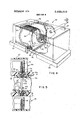
- FIG. 5 is a partial vertical sectional view taken along the lines 55 of FIG. 3;
- FIG. 6 is a vertical sectional view taken along the lines 66 of FIG. 3;
- FIGS. 7A and 7B are plan views of a portion of the wafer holding mechanism in the chamber of FIGS. 3 through 6 in the detaining and releasing position, respectively;
- FIG. 8 is a view in perspective, with portions broken away, of an alternative embodiment of the valve constructed in accordance with the present invention.
- FIG. 9 is a cross-sectional view of an alternative form of the valve of FIG. 8;
- FIG. 10 is a view in perspective, with portions broken away, of a still another embodiment of the invention.
- the rotor 14 is cylindrical in shape and is mounted within the chamber for rotation about an axis 16.
- O-ring seals 18 and 20 are positioned in circumferential grooves at opposite ends of the rotor. These restrict fluid flow along the rotor. With the valve pumped'as described below, even these seals may be omitted.
- An elongated bore 22 extends through the rotor 14 along a diametral line transverse to the axis of rotation 16.
- the surface of the rotor 14 is spaced a slight distance from the walls 24 (see FIG. 5) of the rotor-receiving chamber within housing 12 to allow the rotor to rotate freely within this chamber.
- the clearance between the rotor surface and the chamber walls forms'a clearance cavity 26 which communicates with an'inlet bore 28 and an outlet bore 30 (see FIGS. 1 and 5) extending through opposite faces 12a and 1212, re-
- the clearance cavity also communicates with an exterior suction pump 32 (see FIG. 6) through a pumping channel formed by main channels 34 and auxiliary channels 36. The latter opens onto the clearance cavity 26.
- a low conductance path through the clearance cavity exists between the inlet port 28 and the auxiliary channels 36, as well as between the outlet port 30 and the channels 36.
- the path is of sufficiently low conductance that, with one side of the valve (e.g., face 12a) exposed to atmosphere and to the other side (e. g., 12b) exposed to a high vacuum (e.g. 10 torr), a moderate vacuum (e.g., 10 torr) can be maintained in the clearance cavity at the position of the auxiliary channels 36 when the pumping channel is connected to a mechanical roughing pump.
- the suction pump which evacuates the clearance cavity of the valve 10 may be continuously connected to the pumping channel of the valve irrespective of whether the valve is opened or closed without imposing an undue load upon It.
- FIG. 2 shows a simplified (completely linear) curve 40 illustrating the expected relation between the pressure P and distance X along the path between the inlet and out ports absent any pumping.
- the linear pressure gradient, AP/Ax is seen to be essentially constant over the entire path length L.
- Curve 42 of FIG. 2 illustrates the effect of pumping the clearance cavity at the midpoint between the inlet and outlet ports to a pressure of 10* torr when atmospheric pressure (760 torr) is assumed to exist on one side of the valve (the inlet port) and a very low pressure (e.g., 10' torr) is assumed to exist on the other side of the valve (the outlet port). Under these conditions, most of the pressure drop through the clearance cavity takes place between the high pressure side of the valve (the inlet port) and the point at which the pumping channel opens onto the clearance cavity.
- the maximum pressure gradient, and therefore the maximum leakage flow occurs along the same pathway.
- This leakage fluid is re moved by the suction pump attached to the pumping channel. Only a small pressure drop takes place over the remaining pathway, that is, between the point at which the pumping channel enters the clearance cavity and the low pressure side of the valve. Accordingly, only a small pressure gradient exists over this part of the leakage path and the flow rate through this portion of the clearance cavity is therefore quite low as illustrated by segment 44 of FIG. 2.
- the leakage into the low pressure side (outlet port) of the valve is greatly reduced over that which would have existed but for the use of the pumping channel.
- FIGS. 3 through 6 show a simple vacuum processing system which advantageously incorporates the valve of the present invention.
- the system illustrated is adapted for ion beam implantation of semiconductor wafers.
- the system 50 has a main vacuum chamber 52, a supply forechamber 54, and a receiving forechamber 56.
- the forechamber 54 (shown in detail in FIG. 4) is mounted on a plate 58 with a vacuum-tight seal (not shown) around the edges to permit its evacuation. It has a cover 60, which is hinged by hinges 62 and 64 (FIG. 4) and a lock 66 firmly holding the cover down when the forechamber is to be evacuated.
- a gasket 68 provides a vacuum-tight seal when the cover is closed.
- the construction of the forechamber 56 is the same as that of the forechamber 54 and accordingly will not be described in detail.
- the forechambers 54 and 56 are evacuated to a moderate vacuum (e.g. torr) by means of a vacuum pump 70 (see FIG. 6), while the chamber 52 is evacuated to a high vacuum (e.g. IO torr) by a vacuum pump 71.
- a casette 72 containing a number of thin, circular semiconductor wafers 74 which are to be processed in the main vacuum chamber 52.
- the casette 74 is formed from a rectangular frame having spacer fingers 76 separating the wafers from each other and an open bottom so that the wafers rest on the surface of plate 58. It also has guides 80 extending along the outside of the shell at the bottom; these ride in ways 82 formed in the upper face of plate 58.
- a rack 84 is formed on one side of the frame of casette 72, and mates with a pinion 86 which is rotated by means of a shaft 88 extending through a wall of forechamber 54.
- the shaft 88 has an O-ring or other type of seal (not shown) at the points of extension through the wall of the forechamber to provide a vacuum seal in which the shaft rotates.
- An elongated bore 90 extends through the plate 58 in alignment with the bore 32 of a valve 10 which is positioned below this plate. (See FIG. 3)
- the shaft 88 As the shaft 88 is rotated, it drives the pinion 86 and advances the casette 72 toward the bore 80.
- the longitudinal (long) dimension of the bore 80 is slightly larger than the diameter of a wafer 74 and the transverse (narrow) dimension of this bore is slightly greater than the thickness of the wafer. Accordingly, when the casette 72 is advanced to a position where a wafer is carried over the bore. it falls into the bore 90. Assuming that the upper valve I0 is opened at this time (see FIG. 5), the wafer 74 drops through the inlet port 28, the rotor bore 22, and the outlet port 30, and thereby passes through the valve 10 into the chamber 52.
- the wafer On entering this chamber, the wafer passes in front of a vertical backer plate 100 (FIG. 7) and is caught by detents I02 and 104 mounted on arms I06 and I08, respectively. These arms are in turn connected to a solenoid 110.
- the wafer is then processed, e.g., by implating ions in it.
- the detents 102, 104 are moved away from the plate I00 via arms 106, 108 and solenoid 110, thereby releasing the wafer. It then travels downwardly through an elongated bore 114 in the lower wall of the chamber 54 and thence through a lower valve 10 in the same manner as it entered the chamber. On leaving the lower valve, it enters a receiving casette l 16 in the lower forechamber 56.
- the construction and the operation of the casette 1 16 is the same as that of the casette 72 and thus need not be discussed in detail.
- FIGS. 7A and 7B The construction and operation of the detents 102, 104 is illustrated more clearly in FIGS. 7A and 7B.
- these detents have a frusto-conical shape tapering outwardly from the plate 100. The distance between them is such that when they are fully retracted as shown in FIG. 7A, they are spaced apart by a distance less than the diameter of the wafer 74. However, when they are extended outwardly of the plate 100, as in FIG. 7B, the wafer 74 slides off these dentents and slides between the arms 106, 108 which are spaced apart at a distance somewhat greater than the diameter of the wafer 74, so that it fits easily between them.
- the pump 71 is energized to start the pumping-down of chamber 52 to the desired vacuum level if this has not already been done.
- the chamber 52 will be evacuated to a pressure of 10" torr.
- the upper and lower valves 10 are closed at this time and the chamber 52 is thus isolated from its environment.
- the chambers 54 and 56 are prepared to supply wafers too, and receive them from, the chamber 52. This is accomplished by loading a casette with the wafers to be processed in the upper chamber 54 and simultaneously loading an empty casette to receive the wafers in the lower chamber 56.
- the vacuum pump 32 is energized to pump the clearance cavity in the valve 10 to a pressure level intermediate that in the chamber 54 and 52 or 52 and 56, respectively. The purpose of this is to reduce the pressure gradiant along the lower portion of the clearance cavity at adjacent the entrance to the chamber 52 as described previously in connection with FIGS. 1 and 2.
- the wafer 74 may begin to be fed to it. This is accomplished by rotating shaft 88 which in turn causes the rack 84 and pinion 86 to advance the casette 72. As the first of the wafers 74 advances to the bore (FIG. 4), the upper valve 10 is turned to the open position (FIG. 5) to provide a straight line. unobstructed path through the plate 58, the upper valve 10, and the wall of the chamber 52. The wafer continues down into the chamber under the force of gravity and is caught by detents I02, I04
- solenoid 110 is energized to thrust detents 102, 104 forwardly of plate 100 and thereby released wafer 74.
- the wafer then falls downwardly through the lower wall of the chamber 52, through the lower valve 10, the lower plate, and then into the lower chamber 56 where it is received by a casette 116.
- wafers are fed to the main vacuum chamber 52 one at a time, processed, and released from this chamber before the next wafer is brought into It.
- a forechamber having a pair of valves in accordance with the present invention, one valve (the inlet valve) communicating between atmospheric pressure and the forechamber, the other (the outlet valve) communicating between the forechamber and the main chamber.
- the volume of the forechamber need only be such as to temporarily accommodate the article to be processed in its transit to the main vacuum chamber.
- the inlet valve of the forechamber is pumped to a pressure intermediate atmospheric pressure and the pressure in the forechamher. while the outlet valve (communicating with the main chamber) is evacuated to a vacuum intermediate the forechamber pressure and the main chamber pressure.
- the article to be processed is passed into the forechamber, this chamber evacuated to the appropriate pressure, and is then fed through the outlet valve to the main vacuum chamber.
- valve of the present invention is capable of maintaining a substantial pressure gradient across it, it is possible to transfer materials directly from atmospheric pressures into the high vacuum-chamber. This will be especially the case where the articles to he transferred are quite small so that the valve bore through which they pass may be of low conductance or when the articles are passed through the valve at a high velocity so that the valves need only be opened momentarily.
- the valve of the present invention is a fast acting valve that can be quickly opened and closed. and that its speed of response is limited almost completely by the moment of inertia of its rotor.
- the valve is formed from a central housing block 132 having a cylindrical bore extending there through for accommodating a corresponding cylindrical rotor 134.
- the rotor has a bore 136 extending through it along a diameter thereof, as well as a pair of longitudinally extending grooves 138 on the surface of the rotor at opposite ends of the bore 136.
- a circumferentially extending groove may have an O ring placed in it to seal the shaft from leakage at that end or may even be left without the 0 rings since the groove will be pumped as described below.
- a shaft 142 is attached to rotor 13 and extends through a sealing plate 144 which in turn is sealed to block 132. The shaft 142 provides a means of rotating the rotor 134.
- end plate 146 At the other end of rotor 134 is an end plate 146 which is also mounted on block 132 and is sealed to this block by O ring 148.
- the end plate 146 has a cylindrical bore 150 cut into its interiorface and fonning a pumping chamber facing the end of the rotor 134 and communicating with the clearance cavity between the rotor 134 and the housing surrounding it.
- a spring 151 seated in a cylindrical groove 153 presses against a boss on rotor 134. The spring helps to control the longitudinal position of the rotor 134.
- a further bore 152 communicates between the exterior of the valve 130 and the pumping chamber.
- a bore 154 providing an inlet port for the valve is formed in the upper surface of block 132 and a corresponding bore (not shown) is positioned in the lower face of this block and aligned with the bore 154 to form an outlet port.
- the position of these bores is such that they are aligned with the bore 136 in rotor 134 when its rotor is rotated 90 degrees from the position shown in FIG. 8, thereby providing a straight line, unobstructed path through the valve 130 from one side to the other.
- the valve is open. In the position shown in FIG. 8, the valve is closed.
- a suction pump is connected to the bore 152 to evacuate the clearance cavity around the rotor 134.
- the grooves on the surface of the rotor 134 provide a low impedance, high conductance path for leakage fluid which enters through inlet port 154 and travels downwardly around the sides of the rotor 134 when the valve is closed (as shown in FIG. 8).
- an intermediate pressure e.g., 10 torr
- FIG. 9 is a cross sectional view of a modified form of the valve shown in FIG. 8 in which a cylindrical rotor 1340 is located in a central block 132a having a cylindrical bore extending through it for receiving the rotor.
- the rotor has a central bore 136 extending through it along a diametral line which is aligned with bores 154 on the top and bottom of the block 132a to form inlet and outlet ports for the valve.
- Grooves 138a are located in the walls of the housing 132a at a position midway along the path between the bores 154 and carry fluid entering the clearance cham her 156 to a pumping chamber at one end of the rotor where it is evacuated as was shown in FIG. 8.
- the width of the clearance cavity is exaggerated in this figure for clarity, as was the case in the preceding figures. In practice, its width should be small, preferably not more than a few hundredths millimeters).
- the operation of the valve FIG. 9 is the same as that of the valve of FIG. 8 and will not be further described.
- H6. is a pictorial view of still another embodiment of valve in accordance with the invention.
- the pumping channel extends through the rotor itself.
- the valve 160 has a housing 162 inside which is rotatably mounted a cylindrical rotor 164.
- the rotor has an elongated bore 166 extending through it along a diametral line from one surface to thee other, and additionally has a bore 168 extending in a longitudinal direction along its axis between one end 168a of the rotor and one end of the bore 166.
- 0 rings 170, 172 are provided at opposite ends of the rotor 164.
- An elongated bore 174 is formed in the upper face of the housing 162, and a corresponding elongated bore (not shown) is formed in the lower face of this housing.
- Bore 166 spans the distance between the 0 rings 170 and 172 and thus the fluid leaking through bore 174 from the top of the housing and travelling around the rotor toward the lower bore in this housing enters the bore 166.
- the fluid reaches this bore, it is swept into the bore and then is exhausted through the bore 168 by means of a suction pump connected to that bore. Accordingly, the leakage through the valve to the lower bore is greatly reduced as was described in connection with the valves of FIGS. 1, 8 and 9.
- FIG. ll a valve in accordance with the present invention using a spherical rotor is illustrated in FIG. ll.
- a valve 180 has a spherical rotor 182 mounted in a sealed housing 184 surrounding the rotor. Cylindrical gaskets 186, 188 are positioned within the housing surrounding bores 190 and 192 in the housing forming inlet and outlet ports. A diamatral bore 194 extends through the rotor 182 and is aligned with the bores 190, 192 when the valve is in the open position, as shown in FIG. 11. A shaft 196 which extends through the housing 184 is rigidly attached to the rotor 182 to rotate the bore 194 out of alignment with the bores 190 and 192 and thereby close the valve.
- the housing 184 forms a chamber surrounding the rotor 182. Fluid which leaks into this chamber from the bore 190 (which is attached to the high pressure side of the valve) is evacuated from this chamber by means of a hollow tube 198 which is connected to a suction pump (not shown). The pump maintains a suitable vacuum (e.g., l0 torr) in the chamber. Thus the leakage through the gasket 188 into the bore 192 on the low pressure side is greatly minimized.
- a suitable vacuum e.g., l0 torr
- l have provided a vacuum valve providing a straight line, unobstructed path from the high pressure side of the valve to the low pressure side.
- the valve is fast acting and is characterized by low leakage and great simplicity, with consequent high reliability at low cost.
- the valve is useful not only in vacuum processing systems, but also in other types of vacuum systems such as particle accelerators. in the latter application, its low moment of inertia insures that it can be closed extremely quickly in the event of an emergency.
- I have provided an improved vacuum processing system which especially utilizes the beneficial characteristics of the valve, but which also can be used with any valve which provides a straight line unobstructed path through the valve.
- the processing system minimizes handling of the articles being vacuum processed, while allowing them to be brought into the main vacuum chamber one at a time.
- the system is simple and reliable to use, and can be provided at relatively low cost.
- a low-leakage, pass through value for maintaining a pressure differential thereacross comprising:
- a valve according to claim 1 in which said rotor comprises a cylinder and in which said rotor bore extends radially through the cylinder.
- a valve according to claim 2 in which said cylinder has an axial bore extending in a longitudinal direction therethrough and in communication with said rotor bore to thereby evacuate the clearance cavity through said rotor bore and said axial bore.
- a valve according to claim 2 in which said cylinder has a plurality of grooves extending in the longitudinal direction along the cylinder surface within the clearance cavity, and communicating with said pumping channel to evacuate fluid from said cavity.
- a valve according to claim 4 in which said grooves are in fluid contact with said rotor bore.
- a valve according to claim 1 in which said rotor comprises a sphere and in which said rotor bore extends through said sphere in a radial direction.
- a low leakage, pass-through valve for isolating a vacuum system from its environment comprising A. a cylindrical rotor having a bore extending therethrough in a radial direction; B. a housing 1. having a chamber for receiving said rotor therein, the walls of said chamber being closely radially spaced from the cylindrical surface of said rotor to define a clearance cavity therewith,
- said pumping channel includes a plurality of auxiliary fluid channels extending through the walls of said chamber into said cavity intermediate the entrance and exit bores for,
- a system for transporting articles to a vacuum chamber one at a time comprising A. a main vacuum chamber in which said articles are to be processed,
- each member I. having a bore extending completely therethrough 2. being rotatable into a first position to align said rotor bore with the corresponding chamber bore to thereby providea path through said valve into said chamber 3. being rotatable into a second position to misalign with rotor bore and the corresponding chamber bore to thereby block access to said chamber through said valve, and
- a system according to claim 10 which includes A. means exterior to said main chamber for holding articles to be processed, and
- a system according to claim 11 which includes means exterior to said main chamber for receiving articles passed from said main chamber through said outlet bore.
- a system according to claim 11 which includes means forming a forechamber enclosing said article holding means and in communication with said main chamber only through said inlet bore.
- a system according to claim 13 which includes means to evacuate said forechamber to a vacuum inter mediate that of the mainchamber and the ambient environment 15.
Abstract
A low-leakage vacuum valve provides direct access to the interior of an evacuated chamber when opened while maintaining a substantial pressure differential when closed. A simplified vacuum chamber uses the valve to advantage in processing materials.
Description
United States Patent Brooks [451 Sept. 3, 1974 [5 LOW LEAKAGE VACUUM VALVE AND 3,340,176 9/1967 Belluso et a1 214/17 B CH M ER USING SAME 3,473,550 10/1969 Van Scoy et a1. 137/625.47-X 3,554,114 1/1971 McPhail 214/17 B ent Norman Brooks, Carllsle. Mass- 3,652,444 2/1972 Lester et al. 214/17 B t v 3,674,160 7/1972 Gutowski 214/17 B Magnet? Pass P F icorpomlon 3,692,044 9 1972 Bondi l37/625.47 x
I North B1llen1ca, Mass.
1221 Filed: 1973 Primary Examiner-Henry T. Klinksiek 21] L N 334,455 Attorney, Agent, or Firm-Cesari and McKenna 52 us. c1. 137/62547, 137/6254, 24/17 B [57] ABSTRACT [5 Cl. 01 A vacuum valve provides access to 1 1 Field of Search-m 214/17 B; 137/62547, 625-4 the interior of an evacuated chamber when opened while maintaining a substantial pressure differential 1 References Clted when closedv A simplified vacuum chamber uses the UNITED STATES PATENTS valve to advantage in processing materials.
2,516,908 8/1950 Pottle 214/17 B 2,845,191 7/1958 McDermott 214/17 B 15 Chums Drawmg F'gures 3,260,383 7/1966 Fitzgerald 214/17'B slmura Phorr) VACUUM PUMP FIG. 2
VACUUM PUMP PATENIEDSEP 31214 SIEUZUF4 FIG.5
PATENTED 55? 31974 3. 8333 .01 8
SHEET-38F 4 54 86 J VACUUM PUMP as VACUUM PUMP VACUUM PUMP E2 )4 104 iz 74 fi4 FIG.7A FIG.7B
PATENIEU 3f? 3 MENU? 4 LOW LEAKAGE VACUUM VALVE AND CHANIBER USING SAME BACKGROUND OF THE INVENTION 1. Field of the Invention The invention relates to valves, more particularly, to valves used in vacuum systems for isolating portions of the system at different pressures.
2. Prior Art Vacuum processing systems are becoming increasingly common in various branches of industry. Long used in connection with the processing of food, or of materials such as oil, vacuum processing has become quite widespread in connection with the fabrication of electronic components and circuits, since it provides a very effective means of controlling contamination during processing. Vacuum systems are also frequently encountered in connection with apparatus such as particle accelerators, which are used for a variety of industrial processing, as well as research purposes.
Particle accelerators and electronic processing devices are good examples of vacuum systems requiring high vacuums, e.g., on the order of 10 torr or lower. For pumping and isolation, these systems require valves which have low leakage when pressures of this magnitude are applied across them. Further, they require some means of readily introducing objects into the evacuated chamber and removing them from the chamber without undue destruction of the vacuum within the chamber.
Heretofore, a variety of valves have been used for these purposes. The most common type is the globe valve in which a bonnet with a compressible gasket is mounted on a threaded stem and pressed firmly against a valve seat to close the'valve. This type of valve is fairly expensive, relatively bulky, and slow acting. And it is not well suited to the passage of solid articles such as semiconductor wafers or other devices through it. A modified form of gate valve having a sliding plate arrangement which alternately covers and uncovers a port in the valve, is more suited to the passage of a device or a straight line beam than a globe valve and is also known. This type of valve is more compact than the gate valve, but is also fairly expensive. Further, this valve usually requires compromise in selecting between a soft seal (which may contaminate the material being processed as the seal wears) and a hard seal (which has a more limited life cycle). Other types of valves such as butterfly valves are also limited in one or more of these respects.
Vacuum processing systems require some mechanism for transferring articles to be processed to and from the vacuum chamber. Heretofore various techniques have been used for this purpose. In one group of transfer devices, exemplified by US. Pat. No. 3,554.1 14, (McPhail), a pressure lock consisting of a forechamber acting as a buffer between the vacuum chamber and the atmosphere and having inlet and outlet valves is used to isolate the vacuum chamber from the atmosphere. The valves used in these forechambers are conventionally bulky. This increases the volume of the chamber over and above that necessary to contain the article to be transferred into the vacuum. and therefore increases the pumping time required to reduce the pressure in this chamber to a value suitable for transfer of the article into the vacuum chamber.
In another type of transfer device, the article to be and the carrier is reciprocated into and out of the vacuum chamber as in US. Pat. No. 3,633,770 (Howard et al.) or rotated into and out of the vacuum chamber as in US. Pat. No. 3,260,383 (Fitzgerald). The carrier volume may be pumped prior to entering the high vacuum region to thereby reduce contamination. Transfer devices of this type are not well suited to the transfer of fragile or brittle materials such as semiconductor wafers, which are especially apt to be damaged during loading into, or unloading from, the transfer device.
During the processing of semiconductor wafers, it is desirable to subject them to a minimum of handling to thereby reduce the possibility of damage to them, as well as to simplify the processing system. Many wafer handling devices currently utilized are expensive, mechanically complex, and very susceptible to causing wafer breakage on the occurrence of small misalignments.
Because of the difficulties in transferring articles into and out of the vacuum chamber, resort is often had to batch processing in which a large number of articles to be processed are loaded into a carrier and the carrier is then brought completely into the vacuum chamber. This is frequently undesirable, since the carrier may bring contaminants into the chamber and these must be removed before processing can begin. Also, there is a possibility of cross-contamination of the articles themselves, since all are in the chamber simultaneously. F urther, if access to one of the articles to be processed is required during the processing, the processing must be halted and the carrier removed from the chamber. The chamber must be re-evacuated before further usage, and this can be time consuming.
ln particle accelerators, the vacuum chamber is in the form of an elongated tube in which the beam is confined. The tube is commonly formed in sections which can be isolated from each other as necessary for repairs. The vacuum valves used for this purpose are quite costly. Further, many are slow acting and are thus incapable of providing rapid closure and isolation in the event of a malfunction such as a leak.
BRIEF DESCRIPTION OF THE INVENTION A. Objects of the Invention Accordingly, it is an object of the invention to provide an improved vacuum valve.
v A further object of the invention is to provide a vacuum valve which can sustain a large pressure difference across it with low leakage.
Another object of the invention is to provide an improved vacuum valve which facilitates the transfer of articles to and from a vacuum chamber.
Still another object of the invention is to provide an improved vacuum valve which provides a straight-line path through the valve when opened.
Yet another object of the invention is to provide a low leakage valve which is relatively compact and is comparatively inexpensive.
Yet another object of the invention is to provide a fastacting compact, low leakage vacuum valve.
A further object of the invention is to provide a vacuumprocessing system which facilitates the transfer of articles to and from a vacuum chamber.
Yet another object of the invention is to provide a simple vacuum processing system for vacuum processing of semiconductor wafers.
B. Brief Summary of the Invention The valve of the present invention comprises a compact, low leakage, high pressure differential, passthrough valve which admits articles to, and passes them from, a vacuum chamber when open, and which maintains a substantial pressure differential between the interior and exterior of the vacuum chamber when closed. The valve comprises a housing having a hollow chamber therein for snugly receiving a rotor. The rotor has a bore extending through it in a direction perpendicular to its axis of rotation. This bore is rotatable into alignment with corresponding bores forming inlet and outlet ports on opposite faces of the housing so that a straight, unobstructed passage from one face of the housing (containing the inlet port) to another face (containing the outlet port) is formed at a given angular orientation of the rotor. When the rotor is rotated by 90 (or some lesser amount, dependent on the transverse dimensions of the bore) from this position, passage through the housing is closed and the valve is then in the closed or sealing position.
The surface of the rotor is closely spaced from the walls of the chamber in which is is mounted (e.g., by 0.01 mm at points of minimum clearance and by somewhat more at other points of minimum clearance) to allow rotation of the rotor. This spacing constitutes a clearance cavity of low conductance through which air or other fluid would normally flow from the inlet bore to the outlet bore, thereby forming a leakage path. However, in the present valve, leakage along this path is minimized by evacuating the clearance cavity through a pumping channel extending through the housing and into the cavity and connecting the cavity to an external pumping source. By evacuating this cavity to an intermediate pressure (e.g., torr) which is readily obtainable by means of mechanical forepumps or roughing-pumps, the pressure gradient between the outlet bore of the housing, which is connected to the vacuum chamber, and a point along the path from the inlet to the outlet through which the pump is connected, can be drastically reduced over the pressure gradient that would exist between these two points without the pump so connected. Since fluid flow through a channel is proportional to the pressure gradient along the channel. the leakage flow from the inlet port to the outlet port is greatly reduced.
The shape of the rotor depends in part on the materials to be passed through the valve and in part on other factors such as the need for a slender valve. For example, in processing semiconductor wafers which are commonly in the form of thin discs, the rotor is preferably cylindrical in shape and the materialpassage bore through it advantageously comprises an elongated slot extending through it from one surface to the other along a diametral line and having a narrow dimension in the circumferential direction and an elongated dimension somewhat larger than the diameter of the disc in the longitudinal direction parallel to the axis of rotation. The use of a cylindrical rotor results in a slender, compact valve. Other rotor shapes, such as spherical rotors, may also be used for this or other applications.
The pumping channel in the valve may be arranged in a variety of ways. In one embodiment this channel comprises a number of spaced apart bores extending into the clearance cavity on opposite sides of the rotor and approximately midway between the inlet and outlet bores in the plane of the central line of the rotor. In this embodiment, the rotor surface is smooth and continuous. In another embodiment, a single pumping channel extends through an end wall of the housing into the clearance cavity. To assist the valve pump in evacuating the clearance cavity, grooves are provided on the rotor surface and these grooves are in direct communication with the pumping channel so that fluid leaking into the valve around the sides of the rotor is swept into these grooves and out through the pumping channel. These grooves may alternatively be formed in the side walls of the chamber housing, rather than on the rotor.
In still another embodiment, the clearance cavity is evacuated through a bore which extends through the rotor. This is accomplished by providing a longitudinal bore extending along the axis of the rotor into the central material bore. When the valve is closed, the opposite ends of the rotor bore are rotated to a position where they are no longer aligned with the inlet and outlet bores of the valve housing but instead face the interior walls of the chamber surrounding the rotor. When a suction pump is connected to the pumping bore, therefore, fluid which leaks through the inlet bore and around the rotor shaft toward the outlet bore is swept into the rotor bore from whence it passes through the pumping bore and out to the suction pump.
This arrangement differs from those described previously in that a relatively high conductance path is presented between the exterior of the chamber and the suction pump through the rotor bore and the pumping channel, when the rotor bore is aligned with the inlet and outlet bores, that is, when the valve is open. Accordingly, in this condition, it is desirable to include a shutoff between the pumping channel and the exterior suction pump which isolates the pump when the valve is open to thereby minimize excessive loads on the pump. When the valve is closed, the leakage path conductance is greatly reduced, and is comparable to the path conductance of the other previously described valves when they are either open or closed.
The valve of the present invention is especially well adapted to a materials processing system incorporating a vacuum chamber into which articles to be processed are to be admitted one at a time to avoid contamination or for other purposes. The system described herein comprises a semiconductor wafer processing chamber having a high vacuum chamber, a wafer supply casette and a wafer receiving casette mounted exterior to the chamber in a forevacuum, and a wafer holding station within the chamber.
Each casette comprises a frame movable along a pair of ways and holding a number of wafers. The supply casette is indexed along the ways a step at a time and carries each wafer to a slot extending through the chamber wall and aligned with the inlet slot of a valve. As each wafer is brought over the chamber slot, it is released from the casette and falls into the slot. A valve of the type described above is positioned with its inlet and outlet ports aligned with this slot. When the valve is opened, it allows the wafer to-drop through directly into the chamber where it falls by gravity to a work holding station for processing. The receiving casette is similarly constructed, and receives each wafer through an exit valve one at a time, from the wafer holding sta tion when processing is completed. Each casette is thus maintained outside the high vacuum chamber at all times and only the article being processed is within the chamber at any time.
The wafer holding station comprises a verticallyoriented plate having a pair of parallel, spaced apart detents or catcher arms in the form of cylindrical rods extending through corresponding bores at the bottom of the plate. The arms are connected on the back side of the plate to a solenoid, which, when activated pushes the arms outwardly of the plate and thereafter retracts them when de-energized; on the front of the plate they terminate in a pair of outwardly sloping frust-conical detents. The arms are spaced apart a distance such that, when the solenoid is energized and the arms are thrust outwardly of the plate, a cylindrical semiconductor wafer can just pass between the arms. When, however, the solenoid is de-energized and the arms retracted, the wafer rests on a portion of each of the detents and is prevented from falling downwardly from the plate. This is an extremely simple yet effective mechanism.
DETAILED DESCRIPTION OF THE INVENTION The foregoing and other and further objects and fea tures of the invention will be more readily understood from the following detailed description of the invention when taken in conjunction with the accompanying drawings in which:
FIG. 1 is a view in perspective, with portions broken away of a low leakage, pass-through valve constructed in accordance with the present invention;
FIG. 2 is a simplified diagram illustrating the relation between pressure and distance along the leakage path between the inlet and outlet bores of the valve;
FIG. 3 is a view in perspective showing the valve of FIG. I applied to a vacuum processing system;
FIG. 4 is a view in perspective showing a casette carrying a number of wafers to be processed;
FIG. 5 is a partial vertical sectional view taken along the lines 55 of FIG. 3;
FIG. 6 is a vertical sectional view taken along the lines 66 of FIG. 3;
FIGS. 7A and 7B are plan views of a portion of the wafer holding mechanism in the chamber of FIGS. 3 through 6 in the detaining and releasing position, respectively;
FIG. 8 is a view in perspective, with portions broken away, of an alternative embodiment of the valve constructed in accordance with the present invention;
FIG. 9 is a cross-sectional view of an alternative form of the valve of FIG. 8;
FIG. 10 is a view in perspective, with portions broken away, of a still another embodiment of the invention;
which is fitted a rotor 14. The rotor 14 is cylindrical in shape and is mounted within the chamber for rotation about an axis 16. O- ring seals 18 and 20 are positioned in circumferential grooves at opposite ends of the rotor. These restrict fluid flow along the rotor. With the valve pumped'as described below, even these seals may be omitted. An elongated bore 22 extends through the rotor 14 along a diametral line transverse to the axis of rotation 16. The surface of the rotor 14 is spaced a slight distance from the walls 24 (see FIG. 5) of the rotor-receiving chamber within housing 12 to allow the rotor to rotate freely within this chamber. The clearance between the rotor surface and the chamber walls forms'a clearance cavity 26 which communicates with an'inlet bore 28 and an outlet bore 30 (see FIGS. 1 and 5) extending through opposite faces 12a and 1212, re-
spectively, of housing 12. The clearance cavity also communicates with an exterior suction pump 32 (see FIG. 6) through a pumping channel formed by main channels 34 and auxiliary channels 36. The latter opens onto the clearance cavity 26.
A low conductance path through the clearance cavity exists between the inlet port 28 and the auxiliary channels 36, as well as between the outlet port 30 and the channels 36. Indeed, the path is of sufficiently low conductance that, with one side of the valve (e.g., face 12a) exposed to atmosphere and to the other side (e. g., 12b) exposed to a high vacuum (e.g. 10 torr), a moderate vacuum (e.g., 10 torr) can be maintained in the clearance cavity at the position of the auxiliary channels 36 when the pumping channel is connected to a mechanical roughing pump. This same vacuum is maintained whether the valve is open (i.e., with rotor bore 22 aligned with inlet bore 28 and outlet bore 30 in which case a straight line unobstructed path through the valve is formed) or whether it is closed, (i.e., with rotor bore 22 rotated out of alignment with the inlet and outlet ports 28, 30 so that the opposite ends of the bore 22 face the interior walls 24 of the chamber within the housing 12). Accordingly, the suction pump which evacuates the clearance cavity of the valve 10 may be continuously connected to the pumping channel of the valve irrespective of whether the valve is opened or closed without imposing an undue load upon It.
As noted previously, leakage paths exist between the inlet and outlet bores 28 and 30, respectively, through the clearance cavity between the rotor and the chamber walls. Absent the pumping channel in the valve 10, the pressure drop along this path between the inlet and outlet ports can be expected to be substantially linear with distance along the path due to the symmetry of the valve structure. Thus, there is essentially a constant pressure gradient between the inlet and outlet ports which results in a substantially constant leakage rate between these ports, since the flow rate is proportional to the pressure gradient. This is illustrated diagrammatically in FIG. 2 which shows a simplified (completely linear) curve 40 illustrating the expected relation between the pressure P and distance X along the path between the inlet and out ports absent any pumping. The linear pressure gradient, AP/Ax, is seen to be essentially constant over the entire path length L.
When a pumping channel is provided, however, and this channel is pumped to a pressure intermediate that exists at the inlet and outlet ports, the slope of the pressure gradient is drastically altered. Curve 42 of FIG. 2 illustrates the effect of pumping the clearance cavity at the midpoint between the inlet and outlet ports to a pressure of 10* torr when atmospheric pressure (760 torr) is assumed to exist on one side of the valve (the inlet port) and a very low pressure (e.g., 10' torr) is assumed to exist on the other side of the valve (the outlet port). Under these conditions, most of the pressure drop through the clearance cavity takes place between the high pressure side of the valve (the inlet port) and the point at which the pumping channel opens onto the clearance cavity. Accordingly, the maximum pressure gradient, and therefore the maximum leakage flow, occurs along the same pathway. This leakage fluid is re moved by the suction pump attached to the pumping channel. Only a small pressure drop takes place over the remaining pathway, that is, between the point at which the pumping channel enters the clearance cavity and the low pressure side of the valve. Accordingly, only a small pressure gradient exists over this part of the leakage path and the flow rate through this portion of the clearance cavity is therefore quite low as illustrated by segment 44 of FIG. 2. Thus, the leakage into the low pressure side (outlet port) of the valve is greatly reduced over that which would have existed but for the use of the pumping channel.
FIGS. 3 through 6 show a simple vacuum processing system which advantageously incorporates the valve of the present invention. The system illustrated is adapted for ion beam implantation of semiconductor wafers. As there shown, the system 50 has a main vacuum chamber 52, a supply forechamber 54, and a receiving forechamber 56. The forechamber 54 (shown in detail in FIG. 4) is mounted on a plate 58 with a vacuum-tight seal (not shown) around the edges to permit its evacuation. It has a cover 60, which is hinged by hinges 62 and 64 (FIG. 4) and a lock 66 firmly holding the cover down when the forechamber is to be evacuated. A gasket 68 provides a vacuum-tight seal when the cover is closed. The construction of the forechamber 56 is the same as that of the forechamber 54 and accordingly will not be described in detail. The forechambers 54 and 56 are evacuated to a moderate vacuum (e.g. torr) by means of a vacuum pump 70 (see FIG. 6), while the chamber 52 is evacuated to a high vacuum (e.g. IO torr) by a vacuum pump 71.
Mounted within forechamber 54 is a casette 72 containing a number of thin, circular semiconductor wafers 74 which are to be processed in the main vacuum chamber 52. The casette 74 is formed from a rectangular frame having spacer fingers 76 separating the wafers from each other and an open bottom so that the wafers rest on the surface of plate 58. It also has guides 80 extending along the outside of the shell at the bottom; these ride in ways 82 formed in the upper face of plate 58. A rack 84 is formed on one side of the frame of casette 72, and mates with a pinion 86 which is rotated by means of a shaft 88 extending through a wall of forechamber 54. The shaft 88, of course, has an O-ring or other type of seal (not shown) at the points of extension through the wall of the forechamber to provide a vacuum seal in which the shaft rotates. An elongated bore 90 extends through the plate 58 in alignment with the bore 32 of a valve 10 which is positioned below this plate. (See FIG. 3)
As the shaft 88 is rotated, it drives the pinion 86 and advances the casette 72 toward the bore 80. The longitudinal (long) dimension of the bore 80 is slightly larger than the diameter of a wafer 74 and the transverse (narrow) dimension of this bore is slightly greater than the thickness of the wafer. Accordingly, when the casette 72 is advanced to a position where a wafer is carried over the bore. it falls into the bore 90. Assuming that the upper valve I0 is opened at this time (see FIG. 5), the wafer 74 drops through the inlet port 28, the rotor bore 22, and the outlet port 30, and thereby passes through the valve 10 into the chamber 52.
On entering this chamber, the wafer passes in front of a vertical backer plate 100 (FIG. 7) and is caught by detents I02 and 104 mounted on arms I06 and I08, respectively. These arms are in turn connected to a solenoid 110. The wafer is then processed, e.g., by implating ions in it. After the processing is complete, the detents 102, 104 are moved away from the plate I00 via arms 106, 108 and solenoid 110, thereby releasing the wafer. It then travels downwardly through an elongated bore 114 in the lower wall of the chamber 54 and thence through a lower valve 10 in the same manner as it entered the chamber. On leaving the lower valve, it enters a receiving casette l 16 in the lower forechamber 56. The construction and the operation of the casette 1 16 is the same as that of the casette 72 and thus need not be discussed in detail.
The construction and operation of the detents 102, 104 is illustrated more clearly in FIGS. 7A and 7B. As there shown, these detents have a frusto-conical shape tapering outwardly from the plate 100. The distance between them is such that when they are fully retracted as shown in FIG. 7A, they are spaced apart by a distance less than the diameter of the wafer 74. However, when they are extended outwardly of the plate 100, as in FIG. 7B, the wafer 74 slides off these dentents and slides between the arms 106, 108 which are spaced apart at a distance somewhat greater than the diameter of the wafer 74, so that it fits easily between them.
The operation of the system shown in FIGS. 3 through 6 can now be understood in detail. To begin the processing operation, the pump 71 is energized to start the pumping-down of chamber 52 to the desired vacuum level if this has not already been done. In application such as an ion beam implatation, the chamber 52 will be evacuated to a pressure of 10" torr. The upper and lower valves 10 are closed at this time and the chamber 52 is thus isolated from its environment. Next, the chambers 54 and 56 are prepared to supply wafers too, and receive them from, the chamber 52. This is accomplished by loading a casette with the wafers to be processed in the upper chamber 54 and simultaneously loading an empty casette to receive the wafers in the lower chamber 56. These chambers are then sealed and the pump energized to thereby evacuate the chambers to a moderate vacuum (e.g., 10 torr). During loading time, the vacuum pump 32 is energized to pump the clearance cavity in the valve 10 to a pressure level intermediate that in the chamber 54 and 52 or 52 and 56, respectively. The purpose of this is to reduce the pressure gradiant along the lower portion of the clearance cavity at adjacent the entrance to the chamber 52 as described previously in connection with FIGS. 1 and 2.
When the chambers 52, 54 and 56 have reached the desired vacuum levels, the wafer 74 may begin to be fed to it. This is accomplished by rotating shaft 88 which in turn causes the rack 84 and pinion 86 to advance the casette 72. As the first of the wafers 74 advances to the bore (FIG. 4), the upper valve 10 is turned to the open position (FIG. 5) to provide a straight line. unobstructed path through the plate 58, the upper valve 10, and the wall of the chamber 52. The wafer continues down into the chamber under the force of gravity and is caught by detents I02, I04
which are retracted at this time. These detents hold the wafer 74 while it is being processed into the chamber 52. On completion of the processing, solenoid 110 is energized to thrust detents 102, 104 forwardly of plate 100 and thereby released wafer 74. The wafer then falls downwardly through the lower wall of the chamber 52, through the lower valve 10, the lower plate, and then into the lower chamber 56 where it is received by a casette 116. Thus, wafers are fed to the main vacuum chamber 52 one at a time, processed, and released from this chamber before the next wafer is brought into It.
If it is desired to transfer articles one at a time from atmospheric pressure into the high vacuum chamber while avoiding undue contamination or depressurization of the latter, one may utilize a forechamber having a pair of valves in accordance with the present invention, one valve (the inlet valve) communicating between atmospheric pressure and the forechamber, the other (the outlet valve) communicating between the forechamber and the main chamber. The volume of the forechamber need only be such as to temporarily accommodate the article to be processed in its transit to the main vacuum chamber. The inlet valve of the forechamber is pumped to a pressure intermediate atmospheric pressure and the pressure in the forechamher. while the outlet valve (communicating with the main chamber) is evacuated to a vacuum intermediate the forechamber pressure and the main chamber pressure. The article to be processed is passed into the forechamber, this chamber evacuated to the appropriate pressure, and is then fed through the outlet valve to the main vacuum chamber.
An afterchamber following the main chamber and having a corresponding pair of valves allows removal of the article in the same way. The 'afterchamber sequence is just the reverse of this and need not be described in detail.
It should be observed here that it is not necessary in all cases to precede the main high vacuum chamber 52 with evacuated forechambers. Since the valve of the present invention is capable of maintaining a substantial pressure gradient across it, it is possible to transfer materials directly from atmospheric pressures into the high vacuum-chamber. This will be especially the case where the articles to he transferred are quite small so that the valve bore through which they pass may be of low conductance or when the articles are passed through the valve at a high velocity so that the valves need only be opened momentarily. In this connection it should be noted that the valve of the present invention is a fast acting valve that can be quickly opened and closed. and that its speed of response is limited almost completely by the moment of inertia of its rotor. One can minimize this moment of inertia by restricting the rotor diameter to an amount consistant with obtaining a desired pressure gradient in theclearance cavity adjacent the high vacuum side, as well as by forming the rotor from materials (e.g., aluminum) having relatively low specific gravity.
Instead of providing a multiplicity of pumping channels opening directly into the clearance cavity between the rotor and the walls of the housing surrounding the rotor, one may instead evacuate the clearance cavity by forming a pumping cavity at one end of the clearance cavity and providing low conductance paths within the clearance cavity which can carry fluids from this cavity directly to the pumping cavity. This is illustrated in FIGS. 8 and 9. In FTG. 8, the valve is formed from a central housing block 132 having a cylindrical bore extending there through for accommodating a corresponding cylindrical rotor 134. The rotor has a bore 136 extending through it along a diameter thereof, as well as a pair of longitudinally extending grooves 138 on the surface of the rotor at opposite ends of the bore 136. (Only one of these grooves is shown in FIG. 8). A circumferentially extending groove may have an O ring placed in it to seal the shaft from leakage at that end or may even be left without the 0 rings since the groove will be pumped as described below. A shaft 142 is attached to rotor 13 and extends through a sealing plate 144 which in turn is sealed to block 132. The shaft 142 provides a means of rotating the rotor 134.
At the other end of rotor 134 is an end plate 146 which is also mounted on block 132 and is sealed to this block by O ring 148. The end plate 146 has a cylindrical bore 150 cut into its interiorface and fonning a pumping chamber facing the end of the rotor 134 and communicating with the clearance cavity between the rotor 134 and the housing surrounding it. A spring 151 seated in a cylindrical groove 153 presses against a boss on rotor 134. The spring helps to control the longitudinal position of the rotor 134. A further bore 152 communicates between the exterior of the valve 130 and the pumping chamber. A bore 154 providing an inlet port for the valve is formed in the upper surface of block 132 and a corresponding bore (not shown) is positioned in the lower face of this block and aligned with the bore 154 to form an outlet port. The position of these bores is such that they are aligned with the bore 136 in rotor 134 when its rotor is rotated 90 degrees from the position shown in FIG. 8, thereby providing a straight line, unobstructed path through the valve 130 from one side to the other. When the rotor is in this position, the valve is open. In the position shown in FIG. 8, the valve is closed.
A suction pump is connected to the bore 152 to evacuate the clearance cavity around the rotor 134. The grooves on the surface of the rotor 134 provide a low impedance, high conductance path for leakage fluid which enters through inlet port 154 and travels downwardly around the sides of the rotor 134 when the valve is closed (as shown in FIG. 8). By connecting a conventional roughing pump to the port 152, the chamber 150, the grooves 138, and the bore 136 can be brought to an intermediate pressure (e.g., 10 torr) which thereby diminishes the pressure gradient, and thus the flow rate, into and through the lower bore on the valve in the same manner as was described in connection with the valve of FIG. 1.
Instead of providing grooves 138 on the surface of the rotor 134, these grooves may be positioned in the side walls of the housing surrounding the rotor; the surface of the rotor is then left smooth. This is illustrated diagramatically in FIG. 9 which is a cross sectional view of a modified form of the valve shown in FIG. 8 in which a cylindrical rotor 1340 is located in a central block 132a having a cylindrical bore extending through it for receiving the rotor. The rotor has a central bore 136 extending through it along a diametral line which is aligned with bores 154 on the top and bottom of the block 132a to form inlet and outlet ports for the valve. Grooves 138a are located in the walls of the housing 132a at a position midway along the path between the bores 154 and carry fluid entering the clearance cham her 156 to a pumping chamber at one end of the rotor where it is evacuated as was shown in FIG. 8. (The width of the clearance cavity is exaggerated in this figure for clarity, as was the case in the preceding figures. In practice, its width should be small, preferably not more than a few hundredths millimeters). The operation of the valve FIG. 9 is the same as that of the valve of FIG. 8 and will not be further described.
H6. is a pictorial view of still another embodiment of valve in accordance with the invention. In this valve, the pumping channel extends through the rotor itself. Thus, the valve 160 has a housing 162 inside which is rotatably mounted a cylindrical rotor 164. The rotor has an elongated bore 166 extending through it along a diametral line from one surface to thee other, and additionally has a bore 168 extending in a longitudinal direction along its axis between one end 168a of the rotor and one end of the bore 166. 0 rings 170, 172 are provided at opposite ends of the rotor 164. An elongated bore 174 is formed in the upper face of the housing 162, and a corresponding elongated bore (not shown) is formed in the lower face of this housing. When the rotor 164 is rotated so that the bore 166 extends in a vertical direction, it is aligned with the upper and lower bores in the housing 162 to provide a straight line, unobstructed passage through the valve 160 from one face of the housing to the other.
So far various forms of the invention have been illustrated in which the circular rotors are used. This configuration of rotor is especially desirable since it results in a minimal valve thickness, that is, minimal distance between outlet and inlet. However, other rotor geometries may also advantageously be used. Thus, a valve in accordance with the present invention using a spherical rotor is illustrated in FIG. ll.
As shown there, a valve 180 has a spherical rotor 182 mounted in a sealed housing 184 surrounding the rotor. Cylindrical gaskets 186, 188 are positioned within the housing surrounding bores 190 and 192 in the housing forming inlet and outlet ports. A diamatral bore 194 extends through the rotor 182 and is aligned with the bores 190, 192 when the valve is in the open position, as shown in FIG. 11. A shaft 196 which extends through the housing 184 is rigidly attached to the rotor 182 to rotate the bore 194 out of alignment with the bores 190 and 192 and thereby close the valve.
The housing 184 forms a chamber surrounding the rotor 182. Fluid which leaks into this chamber from the bore 190 (which is attached to the high pressure side of the valve) is evacuated from this chamber by means of a hollow tube 198 which is connected to a suction pump (not shown). The pump maintains a suitable vacuum (e.g., l0 torr) in the chamber. Thus the leakage through the gasket 188 into the bore 192 on the low pressure side is greatly minimized.
For the foregoing it will be seen that l have provided a vacuum valve providing a straight line, unobstructed path from the high pressure side of the valve to the low pressure side. The valve is fast acting and is characterized by low leakage and great simplicity, with consequent high reliability at low cost. The valve is useful not only in vacuum processing systems, but also in other types of vacuum systems such as particle accelerators. in the latter application, its low moment of inertia insures that it can be closed extremely quickly in the event of an emergency.
Further, I have provided an improved vacuum processing system which especially utilizes the beneficial characteristics of the valve, but which also can be used with any valve which provides a straight line unobstructed path through the valve. The processing system minimizes handling of the articles being vacuum processed, while allowing them to be brought into the main vacuum chamber one at a time. The system is simple and reliable to use, and can be provided at relatively low cost.
It will be understood that the foregoing description is illustrative only and is not to be taken in a limiting sense, the exact scope of the invention being defined in the claims.
Having illustrated and described my invention, I claim:
1. A low-leakage, pass through value for maintaining a pressure differential thereacross, comprising:
A. a rotor having a bore extending completely therethrough;
B. a housing 1. having a chamber i. receiving said rotor therein.
ii. having walls closely spaced from the surface of the rotor and defining a clearance cavity therewith;
iii. having inlet and outlet bores alignable with said rotor bore for passing an article from said inlet bore to said outlet bore through said rotor bore when said bores are aligned, and
2. having a pumping channel for connecting said cavity to a vacuum pump for evacuating said cavity.
2. A valve according to claim 1 in which said rotor comprises a cylinder and in which said rotor bore extends radially through the cylinder.
3. A valve according to claim 2 in which said cylinder has an axial bore extending in a longitudinal direction therethrough and in communication with said rotor bore to thereby evacuate the clearance cavity through said rotor bore and said axial bore.
4. A valve according to claim 2 in which said cylinder has a plurality of grooves extending in the longitudinal direction along the cylinder surface within the clearance cavity, and communicating with said pumping channel to evacuate fluid from said cavity.
5. A valve according to claim 4 in which said grooves are in fluid contact with said rotor bore.
.6. A valve according to claim 2 in which said pumping channel includes a plurality of auxiliary channels extending through the walls of the housing and in fluid communication with said cavity for evacuating fluid therefrom.
7. A valve according to claim 1 in which said rotor comprises a sphere and in which said rotor bore extends through said sphere in a radial direction.
8. A low leakage, pass-through valve for isolating a vacuum system from its environment comprising A. a cylindrical rotor having a bore extending therethrough in a radial direction; B. a housing 1. having a chamber for receiving said rotor therein, the walls of said chamber being closely radially spaced from the cylindrical surface of said rotor to define a clearance cavity therewith,
2. having at least one pumping port communicating between said clearance cavity and the exterior of said housing,
3. having an entrance bore and an exit bore extending through said housing and alignable with said rotor bore when said rotor is rotated to a first position, the entrance and exit bores being sealed by the cylindrical surface of said rotor when said member is rotated to a second position.
9. A valve according to claim 8 in which said pumping channel includes a plurality of auxiliary fluid channels extending through the walls of said chamber into said cavity intermediate the entrance and exit bores for,
evacuating fluid from said cavity.
10. A system for transporting articles to a vacuum chamber one at a time, comprising A. a main vacuum chamber in which said articles are to be processed,
B. means forming inlet and outlet bores extending through the walls of said chamber for passage of said materials therethrough,
C. a rotary member positioned in each of said bores,
each member I. having a bore extending completely therethrough 2. being rotatable into a first position to align said rotor bore with the corresponding chamber bore to thereby providea path through said valve into said chamber 3. being rotatable into a second position to misalign with rotor bore and the corresponding chamber bore to thereby block access to said chamber through said valve, and
D. means to advance said articles to said chamber bores one at a time.
11. A system according to claim 10 which includes A. means exterior to said main chamber for holding articles to be processed, and
B. means for advancing said articles to said inlet bore for passage of said articles therethrough one at a time.
12. A system according to claim 11 which includes means exterior to said main chamber for receiving articles passed from said main chamber through said outlet bore.
13. A system according to claim 11 which includes means forming a forechamber enclosing said article holding means and in communication with said main chamber only through said inlet bore.
14. A system according to claim 13 which includes means to evacuate said forechamber to a vacuum inter mediate that of the mainchamber and the ambient environment 15. A system according to claim 13 in which said forechamber includes a bore extending through a portion therof and a rotary member positioned in said bore, said rotary member having a bore extending therethrough alignable with the chamber bore by rotation of said member to provide a path extending from said forechamber into said main chamber when so aligned.
. UNITED STATES PATENT OFFICE CERTIFICATE CORRECTION 3,833,018 September 3, 1974 Patent No. Dated Inventor(s) Norman B BIOOkS It is certified that error appears in the above-identified patent and that said Letters Patent are hereby corrected as shown below:
Claim 1, line 1, "value" should read valve Claim 10,-paragraph 0, sub paragraph 3, line 5, "with rotor" should read. said rotor Signed and sealed this 3rd day of December 1974.
(SEAL) Attest: v
McCOY M. GIBSON JR. C. MARSHALL DANN Attesting Officer Commissioner of Patents FORM PO-1050-(10-69) USCOMWDC 6037M, i U.S. GOVERNMENT P RINTING OFFICE 1989 O'356-33l,
Claims (20)
1. A low-leakage, pass through value for maintaining a pressure differential thereacross, comprising: A. a rotor having a bore extending completely therethrough; B. a housing 1. having a chamber i. receiving said rotor therein. ii. having walls closely spaced from the surface of the rotor and defining a clearance cavity therewith; iii. having inlet and outlet bores alignable with said rotor bore for passing an article from said inlet bore to said outlet bore through said rotor bore when said bores are aligned, and 2. having a pumping channel for connecting said cavity to a vacuum pump for evacuating said cavity.
2. having a pumping channel for connecting said cavity to a vacuum pump for evacuating said cavity.
2. A valve according to claim 1 in which said rotor comprises a cylinder and in which said rotor bore extends radially through the cylinder.
2. having at least one pumping port communicating between said clearance cavity and the exterior of said housing,
2. being rotatable into a first position to align said rotor bore with the corresponding chamber bore to thereby provide a path through said valve into said chamber
3. being rotatable into a second position to misalign with rotor bore and the corresponding chamber bore to thereby block access to said chamber through said valve, and D. means to advance said articles to said chamber bores one at a time.
3. having an entrance bore and an exit bore extending through said housing and alignable with said rotor bore when said rotor is rotated to a first position, the entrance and exit bores being sealed by the cylindrical surface of said rotor when said member is rotated to a second position.
3. A valve according to claim 2 in which said cylinder has an axial bore extending in a longitudinal direction therethrough and in communication with said rotor bore to thereby evacuate the clearance cavity through said rotor bore and said axial bore.
4. A valve according to claim 2 in which said cylinder has a plurality of grooves extending in the longitudinal direction along the cylinder surface within the clearance cavity, and communicating with said pumping channel to evacuate fluid from said cavity.
5. A valve according to claim 4 in which said grooves are in fluid contact with said rotor bore.
6. A valve according to claim 2 in which said pumping channel includes a plurality of auxiliary channels extending through the walls of the housing and in fluid communication with said cavity for evacuating fluid therefrom.
7. A valve according to claim 1 in which said rotor comprises a sphere and in which said rotor bore extends through said sphere in a radial direction.
8. A low leakage, pass-through valve for isolating a vacuum system from its environment comprising A. a cylindrical rotor having a bore extending therethrough in a radial direction; B. a housing
9. A valve according to claim 8 in which said pumping channel includes a plurality of auxiliary fluid channels extending through the walls of said chamber into said cavity intermediate the entrance and exit bores for evacuating fluid from said cavity.
10. A system for transporting articles to a vacuum chamber one at a time, comprising A. a main vacuum chamber in which said articles are to be processed, B. means forming inlet and outlet bores extending through the walls of said chamber for passage of said materials therethrough, C. a rotary member positioned in each of said bores, each member
11. A system according to claim 10 which includes A. means exterior to said main chamber for holding articles to be processed, and B. means for advancing said articles to said inlet bore for passage of said articles therethrough one at a time.
12. A system according to claim 11 which includes means exterior to said main chamber for receiving articles passed from said main chamber through said outlet bore.
13. A system according to claim 11 which includes means forming a forechamber enclosing said article holding means and in communication with said main chamber only through said inlet bore.
14. A system according to claim 13 which includes means to evacuate said forechamber to a vacuum intermediate that of the mainchamber and the ambient environment
15. A system according to claim 13 in which said forechamber includes a bore extending through a portion therof and a rotary member positioned in said bore, said rotary member having a bore extending therethrough alignable with the chamber bore by rotation of said member to provide a path extending from said forechamber into said main chamber when so aligned.
Priority Applications (6)
| Application Number | Priority Date | Filing Date | Title |
|---|---|---|---|
| US33445573 US3833018A (en) | 1973-02-21 | 1973-02-21 | Low leakage vacuum valve and chamber using same |
| FR7405805A FR2224684B1 (en) | 1973-02-21 | 1974-02-20 | |
| CA193,045A CA1016560A (en) | 1973-02-21 | 1974-02-20 | Low leakage vacuum valve and chamber using same |
| DE2408406A DE2408406C3 (en) | 1973-02-21 | 1974-02-21 | Sluice cock |
| GB804574A GB1468462A (en) | 1973-02-21 | 1974-02-21 | Low leakage vacuum valve |
| JP49020981A JPS5833658B2 (en) | 1973-02-21 | 1974-02-21 | Low leakage through valve |
Applications Claiming Priority (1)
| Application Number | Priority Date | Filing Date | Title |
|---|---|---|---|
| US33445573 US3833018A (en) | 1973-02-21 | 1973-02-21 | Low leakage vacuum valve and chamber using same |
Publications (1)
| Publication Number | Publication Date |
|---|---|
| US3833018A true US3833018A (en) | 1974-09-03 |
Family
ID=23307287
Family Applications (1)
| Application Number | Title | Priority Date | Filing Date |
|---|---|---|---|
| US33445573 Expired - Lifetime US3833018A (en) | 1973-02-21 | 1973-02-21 | Low leakage vacuum valve and chamber using same |
Country Status (6)
| Country | Link |
|---|---|
| US (1) | US3833018A (en) |
| JP (1) | JPS5833658B2 (en) |
| CA (1) | CA1016560A (en) |
| DE (1) | DE2408406C3 (en) |
| FR (1) | FR2224684B1 (en) |
| GB (1) | GB1468462A (en) |
Cited By (9)
| Publication number | Priority date | Publication date | Assignee | Title |
|---|---|---|---|---|
| US4030622A (en) * | 1975-05-23 | 1977-06-21 | Pass-Port Systems, Inc. | Wafer transport system |
| US4498832A (en) * | 1982-05-21 | 1985-02-12 | The Boc Group, Inc. | Workpiece accumulating and transporting apparatus |
| US4544317A (en) * | 1984-04-16 | 1985-10-01 | International Business Machines Corporation | Vacuum-to-vacuum entry system apparatus |
| US4676884A (en) * | 1986-07-23 | 1987-06-30 | The Boc Group, Inc. | Wafer processing machine with evacuated wafer transporting and storage system |
| US5213775A (en) * | 1990-06-21 | 1993-05-25 | Dall'argine & Ghiretti S.R.L. | Device for passing objects between two environments separated from each other under sealed conditions, in particular for sterilization or pasteurization plants |
| WO2000022186A1 (en) * | 1998-10-13 | 2000-04-20 | Vacumetal B.V. | Apparatus for flow-line treatment of articles in an artificial medium |
| US6595957B1 (en) | 2000-01-31 | 2003-07-22 | Ethicon, Inc. | Surgical fluid management system with a dampening chamber |
| US7204821B1 (en) * | 2000-01-31 | 2007-04-17 | Ethicon, Inc. | Surgical fluid management system with suction control |
| CN109219872A (en) * | 2016-06-02 | 2019-01-15 | 应用材料公司 | For continuously drawing the gate valve of processing |
Families Citing this family (3)
| Publication number | Priority date | Publication date | Assignee | Title |
|---|---|---|---|---|
| JPH0218836U (en) * | 1988-07-26 | 1990-02-07 | ||
| US6135138A (en) * | 2000-02-01 | 2000-10-24 | Raytheon Company | Rotary coupler for fluid conduits |
| US8833383B2 (en) | 2011-07-20 | 2014-09-16 | Ferrotec (Usa) Corporation | Multi-vane throttle valve |
Citations (9)
| Publication number | Priority date | Publication date | Assignee | Title |
|---|---|---|---|---|
| US2516908A (en) * | 1945-09-24 | 1950-08-01 | American Can Co | Apparatus for lining can ends |
| US2845191A (en) * | 1957-02-05 | 1958-07-29 | Lever Brothers Ltd | Air lock device |
| US3260383A (en) * | 1964-08-04 | 1966-07-12 | Vacuum Processes Inc | Method and apparatus for loading and unloading a high vacuum process chamber |
| US3340176A (en) * | 1965-07-28 | 1967-09-05 | Western Electric Co | Vacuum processing machine |
| US3473550A (en) * | 1967-03-29 | 1969-10-21 | Helmerich & Payne | Pig diverter |
| US3554114A (en) * | 1968-03-07 | 1971-01-12 | P & S Rice Mills Inc | Apparatus for introducing materials into or removing materials from a hermetically sealed vessel |
| US3652444A (en) * | 1969-10-24 | 1972-03-28 | Ibm | Continuous vacuum process apparatus |
| US3674160A (en) * | 1971-04-08 | 1972-07-04 | Heinz Co H J | Apparatus for transferring can lids through a partition subject to a pressure differential |
| US3692041A (en) * | 1971-01-04 | 1972-09-19 | Gen Electric | Variable flow distributor |
Family Cites Families (4)
| Publication number | Priority date | Publication date | Assignee | Title |
|---|---|---|---|---|
| DE558787C (en) * | 1928-11-22 | 1932-09-12 | Elektrowerke Akt Ges | Control device for taps serving as a quick-closing device |
| BE429854A (en) * | 1937-08-24 | |||
| DE1450586B2 (en) * | 1964-08-14 | 1971-12-16 | Max-Planck-Gesellschaft zur Förderung der Wissenschaften e.V., 8000 München | VENTILABLE VALVE FOR LARGE PRESSURE DIFFERENCES |
| GB1284262A (en) * | 1968-09-09 | 1972-08-02 | Unilever Ltd | A device for passing a product between zones of different pressure |
-
1973
- 1973-02-21 US US33445573 patent/US3833018A/en not_active Expired - Lifetime
-
1974
- 1974-02-20 FR FR7405805A patent/FR2224684B1/fr not_active Expired
- 1974-02-20 CA CA193,045A patent/CA1016560A/en not_active Expired
- 1974-02-21 GB GB804574A patent/GB1468462A/en not_active Expired
- 1974-02-21 JP JP49020981A patent/JPS5833658B2/en not_active Expired
- 1974-02-21 DE DE2408406A patent/DE2408406C3/en not_active Expired
Patent Citations (9)
| Publication number | Priority date | Publication date | Assignee | Title |
|---|---|---|---|---|
| US2516908A (en) * | 1945-09-24 | 1950-08-01 | American Can Co | Apparatus for lining can ends |
| US2845191A (en) * | 1957-02-05 | 1958-07-29 | Lever Brothers Ltd | Air lock device |
| US3260383A (en) * | 1964-08-04 | 1966-07-12 | Vacuum Processes Inc | Method and apparatus for loading and unloading a high vacuum process chamber |
| US3340176A (en) * | 1965-07-28 | 1967-09-05 | Western Electric Co | Vacuum processing machine |
| US3473550A (en) * | 1967-03-29 | 1969-10-21 | Helmerich & Payne | Pig diverter |
| US3554114A (en) * | 1968-03-07 | 1971-01-12 | P & S Rice Mills Inc | Apparatus for introducing materials into or removing materials from a hermetically sealed vessel |
| US3652444A (en) * | 1969-10-24 | 1972-03-28 | Ibm | Continuous vacuum process apparatus |
| US3692041A (en) * | 1971-01-04 | 1972-09-19 | Gen Electric | Variable flow distributor |
| US3674160A (en) * | 1971-04-08 | 1972-07-04 | Heinz Co H J | Apparatus for transferring can lids through a partition subject to a pressure differential |
Cited By (11)
| Publication number | Priority date | Publication date | Assignee | Title |
|---|---|---|---|---|
| US4030622A (en) * | 1975-05-23 | 1977-06-21 | Pass-Port Systems, Inc. | Wafer transport system |
| US4498832A (en) * | 1982-05-21 | 1985-02-12 | The Boc Group, Inc. | Workpiece accumulating and transporting apparatus |
| US4544317A (en) * | 1984-04-16 | 1985-10-01 | International Business Machines Corporation | Vacuum-to-vacuum entry system apparatus |
| US4676884A (en) * | 1986-07-23 | 1987-06-30 | The Boc Group, Inc. | Wafer processing machine with evacuated wafer transporting and storage system |
| US5213775A (en) * | 1990-06-21 | 1993-05-25 | Dall'argine & Ghiretti S.R.L. | Device for passing objects between two environments separated from each other under sealed conditions, in particular for sterilization or pasteurization plants |
| WO2000022186A1 (en) * | 1998-10-13 | 2000-04-20 | Vacumetal B.V. | Apparatus for flow-line treatment of articles in an artificial medium |
| EP0995812A1 (en) * | 1998-10-13 | 2000-04-26 | Vacumetal B.V. | Apparatus for flow-line treatment of articles in an artificial medium |
| US6517692B1 (en) | 1998-10-13 | 2003-02-11 | Vacumetal B.V. | Apparatus for flow-line treatment of articles in an artificial medium |
| US6595957B1 (en) | 2000-01-31 | 2003-07-22 | Ethicon, Inc. | Surgical fluid management system with a dampening chamber |
| US7204821B1 (en) * | 2000-01-31 | 2007-04-17 | Ethicon, Inc. | Surgical fluid management system with suction control |
| CN109219872A (en) * | 2016-06-02 | 2019-01-15 | 应用材料公司 | For continuously drawing the gate valve of processing |
Also Published As
| Publication number | Publication date |
|---|---|
| DE2408406C3 (en) | 1981-08-27 |
| JPS5833658B2 (en) | 1983-07-21 |
| CA1016560A (en) | 1977-08-30 |
| DE2408406B2 (en) | 1980-12-11 |
| DE2408406A1 (en) | 1974-08-22 |
| GB1468462A (en) | 1977-03-30 |
| FR2224684B1 (en) | 1978-01-06 |
| FR2224684A1 (en) | 1974-10-31 |
| JPS5041129A (en) | 1975-04-15 |
Similar Documents
| Publication | Publication Date | Title |
|---|---|---|
| US3833018A (en) | Low leakage vacuum valve and chamber using same | |
| KR0136266B1 (en) | Clean transfer method and system therefor | |
| KR920005622B1 (en) | Cathode sputtering apparatus | |
| US8870512B2 (en) | Sealed substrate carriers and systems and methods for transporting substrates | |
| JPH054666A (en) | Vacuum cassette having air vent hole for semiconductor wafer | |
| JPH0774228A (en) | Method and equipment for reverting sample in treating process | |
| JP2005330967A (en) | Vacuum pump system for light gas | |
| EP1107292B1 (en) | Apparatus and process for controlling a mini-environment | |
| US4938858A (en) | Cathode sputtering system | |
| JP2635099B2 (en) | Plasma reactor with vacuum load lock | |
| JP4275769B2 (en) | Substrate transfer device | |
| US4544317A (en) | Vacuum-to-vacuum entry system apparatus | |
| US9673076B2 (en) | System and method for rotational transfer of articles between vacuum and non-vacuum environments | |
| KR920003631B1 (en) | Apparatus for accpting and holding sub-strate | |
| US3428197A (en) | Vacuum entry mechanism | |
| US4787831A (en) | Dual seal system for roots blower | |
| GB2156582A (en) | Small part transport system | |
| US3894926A (en) | In-out transporter for an enclosed chamber | |
| US3699997A (en) | Automated vacuum port | |
| JPH0783011B2 (en) | Decompression treatment method and device | |
| JPS61236971A (en) | Sealing method for magnetic fluid seal | |
| JPS60160139A (en) | Shifting process | |
| JPH04347070A (en) | Multistage magnetic fluid sealing device for vacuum | |
| JPH05306779A (en) | Gate valve | |
| JPH0815081A (en) | Transferring device for vacuum chamber |