EP2728653B1 - Lithium ion secondary cell - Google Patents
Lithium ion secondary cell Download PDFInfo
- Publication number
- EP2728653B1 EP2728653B1 EP11868736.7A EP11868736A EP2728653B1 EP 2728653 B1 EP2728653 B1 EP 2728653B1 EP 11868736 A EP11868736 A EP 11868736A EP 2728653 B1 EP2728653 B1 EP 2728653B1
- Authority
- EP
- European Patent Office
- Prior art keywords
- active material
- particles
- side region
- mix layer
- material mix
- Prior art date
- Legal status (The legal status is an assumption and is not a legal conclusion. Google has not performed a legal analysis and makes no representation as to the accuracy of the status listed.)
- Active
Links
Images

Classifications
-
- H—ELECTRICITY
- H01—ELECTRIC ELEMENTS
- H01M—PROCESSES OR MEANS, e.g. BATTERIES, FOR THE DIRECT CONVERSION OF CHEMICAL ENERGY INTO ELECTRICAL ENERGY
- H01M4/00—Electrodes
- H01M4/02—Electrodes composed of, or comprising, active material
- H01M4/64—Carriers or collectors
- H01M4/66—Selection of materials
- H01M4/661—Metal or alloys, e.g. alloy coatings
-
- H—ELECTRICITY
- H01—ELECTRIC ELEMENTS
- H01M—PROCESSES OR MEANS, e.g. BATTERIES, FOR THE DIRECT CONVERSION OF CHEMICAL ENERGY INTO ELECTRICAL ENERGY
- H01M4/00—Electrodes
- H01M4/02—Electrodes composed of, or comprising, active material
- H01M4/04—Processes of manufacture in general
- H01M4/0402—Methods of deposition of the material
- H01M4/0404—Methods of deposition of the material by coating on electrode collectors
-
- H—ELECTRICITY
- H01—ELECTRIC ELEMENTS
- H01M—PROCESSES OR MEANS, e.g. BATTERIES, FOR THE DIRECT CONVERSION OF CHEMICAL ENERGY INTO ELECTRICAL ENERGY
- H01M10/00—Secondary cells; Manufacture thereof
- H01M10/05—Accumulators with non-aqueous electrolyte
- H01M10/052—Li-accumulators
- H01M10/0525—Rocking-chair batteries, i.e. batteries with lithium insertion or intercalation in both electrodes; Lithium-ion batteries
-
- H—ELECTRICITY
- H01—ELECTRIC ELEMENTS
- H01M—PROCESSES OR MEANS, e.g. BATTERIES, FOR THE DIRECT CONVERSION OF CHEMICAL ENERGY INTO ELECTRICAL ENERGY
- H01M4/00—Electrodes
- H01M4/02—Electrodes composed of, or comprising, active material
- H01M4/04—Processes of manufacture in general
- H01M4/043—Processes of manufacture in general involving compressing or compaction
-
- H—ELECTRICITY
- H01—ELECTRIC ELEMENTS
- H01M—PROCESSES OR MEANS, e.g. BATTERIES, FOR THE DIRECT CONVERSION OF CHEMICAL ENERGY INTO ELECTRICAL ENERGY
- H01M4/00—Electrodes
- H01M4/02—Electrodes composed of, or comprising, active material
- H01M4/04—Processes of manufacture in general
- H01M4/0471—Processes of manufacture in general involving thermal treatment, e.g. firing, sintering, backing particulate active material, thermal decomposition, pyrolysis
-
- H—ELECTRICITY
- H01—ELECTRIC ELEMENTS
- H01M—PROCESSES OR MEANS, e.g. BATTERIES, FOR THE DIRECT CONVERSION OF CHEMICAL ENERGY INTO ELECTRICAL ENERGY
- H01M4/00—Electrodes
- H01M4/02—Electrodes composed of, or comprising, active material
- H01M4/13—Electrodes for accumulators with non-aqueous electrolyte, e.g. for lithium-accumulators; Processes of manufacture thereof
- H01M4/139—Processes of manufacture
-
- H—ELECTRICITY
- H01—ELECTRIC ELEMENTS
- H01M—PROCESSES OR MEANS, e.g. BATTERIES, FOR THE DIRECT CONVERSION OF CHEMICAL ENERGY INTO ELECTRICAL ENERGY
- H01M4/00—Electrodes
- H01M4/02—Electrodes composed of, or comprising, active material
- H01M2004/021—Physical characteristics, e.g. porosity, surface area
-
- H—ELECTRICITY
- H01—ELECTRIC ELEMENTS
- H01M—PROCESSES OR MEANS, e.g. BATTERIES, FOR THE DIRECT CONVERSION OF CHEMICAL ENERGY INTO ELECTRICAL ENERGY
- H01M4/00—Electrodes
- H01M4/02—Electrodes composed of, or comprising, active material
- H01M4/13—Electrodes for accumulators with non-aqueous electrolyte, e.g. for lithium-accumulators; Processes of manufacture thereof
- H01M4/131—Electrodes based on mixed oxides or hydroxides, or on mixtures of oxides or hydroxides, e.g. LiCoOx
-
- H—ELECTRICITY
- H01—ELECTRIC ELEMENTS
- H01M—PROCESSES OR MEANS, e.g. BATTERIES, FOR THE DIRECT CONVERSION OF CHEMICAL ENERGY INTO ELECTRICAL ENERGY
- H01M4/00—Electrodes
- H01M4/02—Electrodes composed of, or comprising, active material
- H01M4/13—Electrodes for accumulators with non-aqueous electrolyte, e.g. for lithium-accumulators; Processes of manufacture thereof
- H01M4/139—Processes of manufacture
- H01M4/1391—Processes of manufacture of electrodes based on mixed oxides or hydroxides, or on mixtures of oxides or hydroxides, e.g. LiCoOx
-
- H—ELECTRICITY
- H01—ELECTRIC ELEMENTS
- H01M—PROCESSES OR MEANS, e.g. BATTERIES, FOR THE DIRECT CONVERSION OF CHEMICAL ENERGY INTO ELECTRICAL ENERGY
- H01M4/00—Electrodes
- H01M4/02—Electrodes composed of, or comprising, active material
- H01M4/36—Selection of substances as active materials, active masses, active liquids
- H01M4/48—Selection of substances as active materials, active masses, active liquids of inorganic oxides or hydroxides
- H01M4/50—Selection of substances as active materials, active masses, active liquids of inorganic oxides or hydroxides of manganese
- H01M4/505—Selection of substances as active materials, active masses, active liquids of inorganic oxides or hydroxides of manganese of mixed oxides or hydroxides containing manganese for inserting or intercalating light metals, e.g. LiMn2O4 or LiMn2OxFy
-
- H—ELECTRICITY
- H01—ELECTRIC ELEMENTS
- H01M—PROCESSES OR MEANS, e.g. BATTERIES, FOR THE DIRECT CONVERSION OF CHEMICAL ENERGY INTO ELECTRICAL ENERGY
- H01M4/00—Electrodes
- H01M4/02—Electrodes composed of, or comprising, active material
- H01M4/36—Selection of substances as active materials, active masses, active liquids
- H01M4/48—Selection of substances as active materials, active masses, active liquids of inorganic oxides or hydroxides
- H01M4/52—Selection of substances as active materials, active masses, active liquids of inorganic oxides or hydroxides of nickel, cobalt or iron
- H01M4/525—Selection of substances as active materials, active masses, active liquids of inorganic oxides or hydroxides of nickel, cobalt or iron of mixed oxides or hydroxides containing iron, cobalt or nickel for inserting or intercalating light metals, e.g. LiNiO2, LiCoO2 or LiCoOxFy
-
- H—ELECTRICITY
- H01—ELECTRIC ELEMENTS
- H01M—PROCESSES OR MEANS, e.g. BATTERIES, FOR THE DIRECT CONVERSION OF CHEMICAL ENERGY INTO ELECTRICAL ENERGY
- H01M4/00—Electrodes
- H01M4/02—Electrodes composed of, or comprising, active material
- H01M4/62—Selection of inactive substances as ingredients for active masses, e.g. binders, fillers
- H01M4/624—Electric conductive fillers
- H01M4/625—Carbon or graphite
-
- Y—GENERAL TAGGING OF NEW TECHNOLOGICAL DEVELOPMENTS; GENERAL TAGGING OF CROSS-SECTIONAL TECHNOLOGIES SPANNING OVER SEVERAL SECTIONS OF THE IPC; TECHNICAL SUBJECTS COVERED BY FORMER USPC CROSS-REFERENCE ART COLLECTIONS [XRACs] AND DIGESTS
- Y02—TECHNOLOGIES OR APPLICATIONS FOR MITIGATION OR ADAPTATION AGAINST CLIMATE CHANGE
- Y02E—REDUCTION OF GREENHOUSE GAS [GHG] EMISSIONS, RELATED TO ENERGY GENERATION, TRANSMISSION OR DISTRIBUTION
- Y02E60/00—Enabling technologies; Technologies with a potential or indirect contribution to GHG emissions mitigation
- Y02E60/10—Energy storage using batteries
-
- Y—GENERAL TAGGING OF NEW TECHNOLOGICAL DEVELOPMENTS; GENERAL TAGGING OF CROSS-SECTIONAL TECHNOLOGIES SPANNING OVER SEVERAL SECTIONS OF THE IPC; TECHNICAL SUBJECTS COVERED BY FORMER USPC CROSS-REFERENCE ART COLLECTIONS [XRACs] AND DIGESTS
- Y02—TECHNOLOGIES OR APPLICATIONS FOR MITIGATION OR ADAPTATION AGAINST CLIMATE CHANGE
- Y02T—CLIMATE CHANGE MITIGATION TECHNOLOGIES RELATED TO TRANSPORTATION
- Y02T10/00—Road transport of goods or passengers
- Y02T10/60—Other road transportation technologies with climate change mitigation effect
- Y02T10/70—Energy storage systems for electromobility, e.g. batteries
Definitions
- the present invention relates to a lithium ion secondary battery including an electrode containing active material particles and a binder.
- Lithium ion secondary batteries have been widely used as power sources for portable equipment such as VTR cameras, notebook computers, and mobile phones, and are now being used in wide fields of game machines, electric power tools, power-assisted bicycles, etc. Further, lithium ion secondary batteries are gathering attention as power sources for electric vehicles due to their high energy densities.
- HEVs Hybrid Electric Vehicles
- PHEV plug-in Hybrid Electric Vehicles
- the HEVs and PHEVs which assist the acceleration forces of vehicles by motor driving, need to have high levels of assisting force, and high outputs of power source batteries are thus required for the HEVs and PHEVs. Further, increasing the energy density of a battery makes it possible to reduce the size of the battery and to increase the driving distance of a PHEV by one charge.
- lithium ion secondary batteries When lithium ion secondary batteries are used as, for example, power sources for HEVs or PHEVs, high output batteries are necessary since momentary charging and discharging are often performed repeatedly at current values of not smaller than approximately 10C, depending on a method of controlling the system, when vehicles are driving.
- the charging and discharging reactions of a lithium ion secondary battery are performed in the vicinity of the interface between active material particles and an electrolyte in an electrode.
- Increasing the output of the lithium ion secondary battery requires a sufficient reaction area of the active material particles and the electrolyte and a sufficient amount of electrolyte near the active material particles to be provided in the reaction region of the active material particles and the electrolyte.
- the electrode includes mixed particles of the active material particles, conductive assisting agent particles, and a binder.
- the present invention has been made in view of the above disadvantages and aims to provide a lithium ion secondary battery capable of achieving a high energy density without reducing the output.
- the lithium ion secondary battery according to the present invention includes an electrode having an active material mix layer on both surfaces of a current collector, the active material mix layer having a smaller void ratio in a current collector side region of the active material mix layer near the collector and a surface side region of the active material mix layer near the surface of the active material mix layer than in the intermediate region between the above two regions.
- the invention is defined in claim 1.
- a lithium ion secondary battery capable of realizing a high energy density while maintaining an output can be provided.
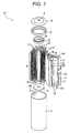
- FIG. 1 is an exploded perspective view illustrating, partially with cross sections, an entire configuration of a cylindrical lithium ion secondary battery, which is a vehicle secondary battery. It is to be understood that although a cylindrical battery will be described in the embodiments, applicable electrodes are not limited to this cylindrical battery and may include other various types of batteries such as a square battery.
- a lithium ion secondary battery D1 includes a positive electrode 14, a negative electrode 15, separators 18 between the electrodes 14 and 15, an electrode group 8, the electrode group 8 formed by winding the positive electrode 14, the negative electrode 15, and the separators 18, a bottomed cylindrical battery container 1 containing the electrode group 8, and a top cover section sealing the upper opening of the battery container 1, as shown in FIG. 1 .
- the battery electrodes (positive electrode and negative electrode) of the electrode group 8 are prepared by forming an active material mix layer containing active materials on both surfaces of a current collector. More specifically, the positive electrode 14 is a strip metal thin film of aluminum, for example, and a positive active material mix layer 16 is formed on both surfaces of the electrode 14, in other words, an inner wound surface and an outer wound surface of the electrode 14.
- the positive active material mix layer 16 is formed by applying a positive active material mix on both surfaces of the positive electrode 14, drying the mix, and sandwiching, pressurizing, and compressing the dried mix and the positive electrode 14 together in the thickness direction.
- a plurality of positive tabs 12 are provided in the long-side part of the upper area of the drawing.
- the negative electrode 15 is formed of a metal thin film (current collector) of copper, for example, and a negative active material mix layer 17 is formed on both surfaces of the electrode 15.
- the negative active material mix layer 17 is formed by applying a negative active material mix on both surfaces of the negative electrode 15, drying the mix, and sandwiching, pressurizing, and compressing the dried mix and the negative electrode 15 together in the thickness direction.
- a plurality of negative tabs 13 are provided in the long-side part of the lower area of the drawing.
- the positive electrode 14 and the negative electrode 15 are wound around a resin axial core 7, with porous and insulating separators 18 interposed between the core 7 and the electrodes.
- the outermost separator 18 is fixed with a tape 19 so that the electrode group 8 is formed.
- an innermost circumferential surface in contact with the axial core 7 is the separator 18 and the outermost circumferential surface is the separator 18 covering the negative electrode 15.
- a positive current collecting ring 5 and a negative current collecting ring 6 are fixed in engagement with each other at both ends of the core 7.
- the positive tabs 12 are welded to the positive current collecting ring 5 by ultrasonic welding, for example.
- the negative tabs 13 are welded to the negative current collecting ring 6 by ultrasonic welding, for example.
- the battery container 1 serving as a negative terminal contains the electrode group 8 wound around the resin axial core 7, with the respective current collecting rings 5 and 6 for the positive and negative electrodes being attached to the electrode group 8.
- the negative current collecting ring 6 is electrically connected to the battery container 1 via a negative lead (not shown in the drawings).
- a non-aqueous electrolyte 20 is injected into the battery container 1.
- a gasket 2 is provided between the battery container 1 and a top cover case 4 to seal the opening of the battery container 1 and obtain electrical insulation between the battery container 1 and the top cover case 4.
- a top cover section is provided on the positive current collecting ring 5 to seal the opening of the battery container 1, is formed of conductive material, and includes a top cover 3 and the top cover case 4.
- the top cover section and the positive electrode of the electrode group 8 are electrically connected in such a manner that one of positive leads 9 is welded to the top cover case 4 and the other is welded to the positive current collecting ring 5.
- the positive active material mix layer 16 includes a positive active material, a positive conductive material, and a positive binder resin.
- a positive active material lithium oxide is desirable. More specifically, lithium cobaltate, lithium manganate, nickel acid lithium, lithium iron phosphate, lithium composite oxide (lithium oxide containing at least two types of cobalt, nickel, and manganese), etc. may be used.
- the positive conductive material is not particularly limited as long as the material is capable of assisting transfer of electrons to the positive electrode, the electrons having generated from occlusion and releasing reactions of lithium ions in the positive active material mix.
- Examples of the positive conductive material include graphite and acetylene black.
- the positive binder resin enables bonding of the positive active material, the positive conductive material, and the positive current collecting material, and is not particularly limited as long as the resin is not significantly degraded due to contact with the electrolyte.
- the positive binder resin include polyvinylidene difluoride (PVDF) or fluororubber.
- the negative active material mix layer 17 usually includes a negative active material, a negative binder resin, and a thickening agent.
- the negative active material mix layer 17 may include a negative conductive material such as acetylene black if needed.
- Examples of the negative active material include carbonic materials such as graphite, soft carbon, and hard carbon.
- PVDF polyvinyl dimethacrylate
- SBR styrene-butadiene copolymer rubber
- NMP N-methylpyrrolidone
- water etc.
- a method for applying the solvent include a slit-die applying method and a rolling method
- examples of the drying method include hot-air circulation, infrared heating, and a combination thereof
- examples of the pressing method include a method of interposing a battery electrode between a pair of cylindrical pressing rollers and allowing the electrode to pass between the rollers so as to pressurize and compress the battery electrode from both sides.
- the active material particles forming the active material mix there are used secondary particles containing voids formed by combining a plurality of primary particles through sintering. Further, the pressure at the pressing (pressurizing and compressing) is adjusted to a predetermined value so that the active material mix layer has a smaller void ratio in the current collector side region and the surface side region of the layer than in the intermediate region between the above two regions. In this way, an electrode is obtained in which the void ratio is reduced and the reaction area of the active material particles and the electrolyte is increased in the two directions from the intermediate region toward the current collector side region and the surface side region.
- an active material mix layer can be formed in which the active material particles have a longer average actual circumferential length in the surface side region and the collector side region than in the intermediate region. With the active material mix layer, it is possible to obtain an electrode in which the void ratio is reduced and the average actual circumferential length of the active material particles is increased in the two directions from the intermediate region toward the surface side region and the collector side region.
- FIG. 2 is a schematic diagram illustrating a cross section in the thickness direction of the electrode according to the embodiments.
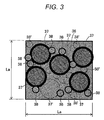
- FIG. 3 is a conceptual diagram of a void ratio and the average actual circumferential length of active material particles per unit cross-sectional area of the inside of the active material mix layer according to the embodiments.
- an active material mix layer 31 is divided in the thickness direction thereof into a surface side region 32, an intermediate region 33, and a current collector side region 34, and the void ratio and the reaction area of the active material particles and the electrolyte are adjusted for the cross-sectional area of each region of the mix layer.
- the void ratio is smaller in the surface side region 32 near the surface of the active material mix layer 31 and the current collector side region 34 near the current collector 35 in the layer 31 than in the intermediate region 33 between the regions 32 and 34.
- the active material particles of the active material mix layer 31 have a longer average actual circumferential length in the surface side region 32 and the current collector side region 34 than in the intermediate region 33.
- the void ratio is a proportion of a void portion 36 (a portion where the cross sections of the active material particles 37 and the conductive assisting agent particles 38 are not observed) per unit area to the cross section of the active material mix layer 31 in the thickness direction thereof (hereinafter referred to as the active material mix layer cross section).
- the reaction area of the active material particles 37 and the electrolyte is defined as the actual circumferential length of the active material particles 37 (a sum of lengths of edge portions of the cross sections of the active material particles 37) per unit area of the active material mix layer cross section.
- the void ratio and the average actual circumferential length are quantifiable by acquiring and analyzing an image of the active material mix layer cross section by, for example, SEM.
- Any active material mix layer cross section is formed of a plurality of cross sections of active material particles and voids, based on which the void ratio and the actual circumferential length of the active material particles per unit area are determined. Further, a void ratio and an average actual circumferential length of the active material particles obtained by similarly analyzing different active material mix layer cross sections correlate with an actual void ratio in three dimensions and an actual area where the active material particles and the electrolyte are in contact with each other in three dimensions. In the embodiments, values obtained from randomly selected 30 cross sections of the active material mix layer are used as the void ratio and the average actual circumferential length.
- the cross sections of the active material particles 37 and the conductive assisting agent particles 38 are observed within the unit area (La ⁇ La) of the active material mix layer cross section, and the portion other than the active material particles 37 and the conductive assisting agent particles 38 is the void portion (space) 36.
- Active material particles 37' and conductive assisting agent particles 38' are located behind the active material mix layer cross section in the image and only the appearances thereof are observed instead of the cross sections. Note that the cross sections are not observed unlike the active material particles 37 and the conductive assisting agent particles 38, and the active material particles 37' and the conductive assisting agent particles 38' have no influence on calculation of the void ratio and the actual circumferential length in a case where the image shown in FIG. 3 is used. The lengths of edge portions of all of the observed cross sections of the active material particles 37 within the unit area are added, and the value thus obtained is the actual circumferential length.
- the voids in the active material mix layer 31 serve as paths for diffusing, to deal with concentration change of Li ions in the layer 31 due to battery reaction, the Li ions so as to permit the equilibrium of the concentration.
- a diffusion resistance for the Li ions is not easily degraded since the distance from a separator (not shown in the drawings) abundantly storing the electrolyte is shorter than in the intermediate region 33 despite a smaller void ratio.
- the diffusion resistance of the Li ions is not easily affected despite a small ratio of voids through which the Li ions are diffused. Hence, it is possible to achieve a high energy density while maintaining the output, by making the void ratio in the surface side region 32 and the current collector side region 34 smaller than in the intermediate region 33.
- a lithium-nickel-manganese-cobalt composite oxide (LiNi 0.33 Mn 0.33 Co 0.33 O 2 ) containing a large number of voids in the particles is employed.
- the void ratio in the inside of the particles roughly ranges from 20% to 50%.
- Positive active material particles, carbon black powder as conductive assisting agent particles, and polyvinylidene difluoride as a binder are mixed in a mixed amount ratio of 85, 10, and 5 parts by weight, to obtain a dispersion solvent.
- the dispersion solvent and N-methylpyrrolidinon are mixed to prepare an active material mix slurry.
- the slurry is applied to a current collector so that the weight of active material particles for one surface is 100 g/m 2 , and is dried, whereby an active material mix layer is formed. Thereafter, a load condition to be provided to an electrode at pressing is made higher and a positive electrode for each of a plurality of embodiments is prepared.
- Comparative Example 1 a positive electrode is prepared having an active material mix layer using as active material particles secondary particles containing a smaller number of voids than in Embodiments 1 to 3. Comparative Example 1 is defined as a reference condition. In Comparative Example 2, a positive electrode is prepared having an active material mix layer with a void ratio which is reduced to approximately 80% of the void ratio in Comparative Example 1 by making the pressing pressure higher than in Comparative Example 1.
- Comparative Example 3 After a slurry is applied to a current collector so that the weight of active material particles is half of the weight in Comparative Example 1, an electrode is pressed and a first active material mix layer (current collector side) is formed. Subsequently, the application and pressing processes of the mix layer is repeated so that a second active material mix layer (surface side) is stacked on the first active material mix layer.
- amorphous carbon powder as negative active material particles and 10 parts by weight of polyvinylidene difluoride as a binder are added to each other so that a dispersion solution is prepared. Subsequently, the solution and N-methylpyrrolidinon are mixed to prepare a negative active material mix slurry. Further, having being applied to both surfaces of a current collector of 10 ⁇ m-thick rolled copper foil, the slurry is dried, is pressed, and is cut. In this way, a negative electrode is prepared.
- the positive electrode and the negative electrode prepared as described above are wound together with a 40 ⁇ m-thick separator of polyethylene, to form an electrode group. Further, after the electrode group and an electrolyte is injected into a cylindrical battery container 1, a top cover is sealed by caulking. In this way, a lithium ion secondary battery is obtained.
- the electrolyte is made of a solvent obtained by mixing ethylene carbonate and dimethyl carbonate in a volume ratio of 1 to 2 and 1 mol of lithium hexafluorophosphate (LiPF 6 ) dissolved in the solvent.
- the prepared positive electrode is subjected to cutting processing to acquire an SEM picture of the cross section of the positive active material mix layer in the thickness direction thereof.
- the picture is analyzed so that the void ratio and the average actual circumferential length of the active material particles per unit area are calculated for each of the upper section, the intermediate section, and the lower section of the positive active material mix layer formed by dividing the inside of the layer into three sections in the thickness direction.
- the output characteristics and the volume energies in the regions are measured and compared.
- the resistance A in the expression (1) is the slope of a line obtained by straight-line approximation using the method of least squares on the basis of the relation between the currents and the corresponding voltages.
- the resistance A is measured after initial capacity stabilizing operation.
- the discharge starting voltage is 4.1 V
- the lower limit voltage is 2.5 V.
- the output in Comparative Example 1 is defined as 100%.
- the volume energy density is calculated from the following expression (2).
- Volume energy density Wh / L 3.6 V ⁇ 1 C discharge capacity ⁇ electrode group volume
- a capacitance value is used obtained by discharging the batteries of the comparative examples and the embodiments from 4.1 V to 2.5 V at the same current value.
- the volume energy density in Comparative Example 1 is defined as 100% for comparison.
- Table 1 shows the outputs and the volume energy densities of the batteries as the battery characteristics of Comparative Examples 2 and 3 in comparison with Comparative Example 1.
- Comparative Example 2 Comparative Example 3 Output Ratio % 92% 94% Volume Energy Density Ratio % 107% 103%
- Table 2 shows proportions of a void ratio and the average actual circumferential length of the active material particles per unit area in the collector side region and the surface side region to those in the intermediate region, in each of Embodiments 1 to 3 and an examining example. Further, Table 2 shows comparisons in the outputs and the volume energy densities of the batteries between Embodiments and the examining example and Comparative Example 1.
- Embodiment 1 Embodiment 2 Embodiment 3 Examining Example Void Ratio Rate % 95% 91% 86% 84% Active Material Actual Circumferential Length Ratio % 109% 118% 127% 136% Output Ratio % 99% 99% 99% 92% Volume Energy Density Ratio % 101% 103% 104% 105%
- the active material particles formed of the secondary particles containing voids are used as described above.
- the active material mix layer is provided with such a distribution that the void ratio is reduced and the average actual circumferential length of the active material particles is increased in directions from the intermediate region to the current collector side region and to the surface side region.
- the pressures at pressing are made higher in the order of Embodiments 1, 2, 3, and the examining example, so that the void ratios are reduced within the range of 95% to 84% and the average actual circumferential lengths of the active material particles are increased within the range of 109% to 136%.
- the volume energy density is improved and the suppressing effect of output reduction is obtained.
- the reduction in output ratio is larger in the examining example than in Embodiments 1 to 3.
- Embodiments 1 to 3 The following is a presumed mechanism of the suppressing effect for the output reduction, which has been confirmed in Embodiments 1 to 3.
- the void ratio is small, the distances from the separators are small and the separators have a higher void ratio and a higher electrolyte concentration than the active material mix layer. This is a reason why the diffusion resistance of Li ions is not easily degraded.
- the proportion of the void ratio in the current collector side region and the surface side region to the void ratio in the intermediate region is desirably in the range of approximately 86% to 95% (the void ratio in the current collector side region and the surface side region/the void ratio in the intermediate region).
- the effect is notable when the actual circumferential length ratio of the active material particles is in the range of approximately 109% to 127% (the average actual circumferential length of the active material particles in the collector side region and the surface side region/the average actual circumferential length of the active material particles in the intermediate region).
- the configuration of the present invention is not limited to the descriptions of the embodiments and various alterations may be made insofar as they are within the gist of the invention.
- active material particles not contain voids may be employed.
- carbon black powder is used as the conductive assisting agent particles in the embodiments, graphite or carbon nanotube such as VGCF may be used alone or in combination.
- VGCF graphite or carbon nanotube
- other binder resins may be used.
- any type of active material particles are applicable as long as lithium ions can be inserted into and desorbed from the particles and the electrode structure may be used for both the positive and negative electrodes.
- active material particles lithium cobaltate, lithium manganate, nickel acid lithium, a composite oxide thereof, lithium titanate, etc. may be used.
- the embodiments use LiPF 6 for the electrolyte and the mixture solvent of ethylene carbonate and dimethyl carbonate as the electrolyte solvent, the lithium salt and organic solvent are not particularly limited.
- the active material mix layer has a smaller void ratio in the collector side region and the surface side region than in the intermediate region therebetween. In this way, there is generated a two-directional distribution in the layer and degradation of Li ions diffusion resistance is thus suppressed as much as possible. Further, since active material particles can be filled into the current collector side region and the surface side region with reduced void ratios, it is possible to realize a high energy density without degrading the output.
- the active material particles with the reduced void ratios can have an increased reaction area of the electrolyte by breaking, thereby preventing reduction in the reaction area of the active material particles and the electrolyte in the voids, resulting in further suppression of degradation of output characteristic.
- a lithium ion secondary battery D1 can be obtained which achieves a high energy density and a high output at one time.
- the advantages of the present invention are not limited to the manufacturing method. Similar advantages can be obtained as well from an electrode having a void ratio that is made smaller than the void ratio in the intermediate section between the lower section and the upper section by stacking active material mix layers of which pressed amount and the diameter of active material particles are changed by using active material particles not containing voids.
Landscapes
- Chemical & Material Sciences (AREA)
- Engineering & Computer Science (AREA)
- Chemical Kinetics & Catalysis (AREA)
- Electrochemistry (AREA)
- General Chemical & Material Sciences (AREA)
- Manufacturing & Machinery (AREA)
- Materials Engineering (AREA)
- Battery Electrode And Active Subsutance (AREA)
Applications Claiming Priority (2)
| Application Number | Priority Date | Filing Date | Title |
|---|---|---|---|
| JP2011144202A JP5651547B2 (ja) | 2011-06-29 | 2011-06-29 | リチウムイオン二次電池 |
| PCT/JP2011/069977 WO2013001660A1 (ja) | 2011-06-29 | 2011-09-02 | リチウムイオン二次電池 |
Publications (3)
| Publication Number | Publication Date |
|---|---|
| EP2728653A1 EP2728653A1 (en) | 2014-05-07 |
| EP2728653A4 EP2728653A4 (en) | 2015-04-08 |
| EP2728653B1 true EP2728653B1 (en) | 2016-11-23 |
Family
ID=47423598
Family Applications (1)
| Application Number | Title | Priority Date | Filing Date |
|---|---|---|---|
| EP11868736.7A Active EP2728653B1 (en) | 2011-06-29 | 2011-09-02 | Lithium ion secondary cell |
Country Status (4)
| Country | Link |
|---|---|
| US (1) | US9472809B2 (enExample) |
| EP (1) | EP2728653B1 (enExample) |
| JP (1) | JP5651547B2 (enExample) |
| WO (1) | WO2013001660A1 (enExample) |
Families Citing this family (9)
| Publication number | Priority date | Publication date | Assignee | Title |
|---|---|---|---|---|
| JP5924541B2 (ja) * | 2013-01-23 | 2016-05-25 | トヨタ自動車株式会社 | 二次電池 |
| JP6211595B2 (ja) | 2013-03-29 | 2017-10-11 | 三洋電機株式会社 | 非水電解質二次電池 |
| ES2962432T3 (es) * | 2014-09-23 | 2024-03-19 | Jiangsu Hengtron Nanotech Co Ltd | Baterías que contienen óxido metálico de litio con capacidad de velocidad mejorada |
| KR101976174B1 (ko) | 2016-02-24 | 2019-05-09 | 주식회사 엘지화학 | 리튬 이차전지용 전극 조립체, 이를 포함하는 리튬 이차전지 및 전지모듈 |
| CN110495035B (zh) * | 2017-03-31 | 2022-07-08 | 株式会社村田制作所 | 锂离子二次电池 |
| JP7069668B2 (ja) * | 2017-12-01 | 2022-05-18 | トヨタ自動車株式会社 | リチウムイオン二次電池 |
| KR102357941B1 (ko) * | 2018-01-29 | 2022-02-03 | 삼성에스디아이 주식회사 | 리튬이차전지용 양극 활물질, 이를 포함하는 양극, 및 이를 포함하는 리튬이차전지 |
| JP7028751B2 (ja) * | 2018-11-16 | 2022-03-02 | トヨタ自動車株式会社 | 圧密化済み帯状電極板の製造方法、圧密化済み帯状電極板及び電池 |
| EP3961751B1 (en) * | 2020-08-31 | 2023-06-28 | Samsung SDI Co., Ltd. | Positive electrode layer for all-solid secondary battery, method of preparing the same, and all-solid secondary battery including the same |
Citations (1)
| Publication number | Priority date | Publication date | Assignee | Title |
|---|---|---|---|---|
| US20020106565A1 (en) * | 2000-12-12 | 2002-08-08 | Matsushita Electric Industrial Co., Ltd. | Positive electrode plate for alkaline storage battery and method for manufacturing the same, and alkaline storage battery using the same |
Family Cites Families (13)
| Publication number | Priority date | Publication date | Assignee | Title |
|---|---|---|---|---|
| US3709446A (en) | 1969-05-09 | 1973-01-09 | M Espy | Sonic boom reduction |
| KR101178643B1 (ko) * | 2001-07-27 | 2012-09-07 | 에이일이삼 시스템즈 인코포레이티드 | 배터리 구조, 자기 조직화 구조 및 관련 방법 |
| JP3709446B2 (ja) | 2002-12-09 | 2005-10-26 | 三井金属鉱業株式会社 | リチウム二次電池用正極活物質及びその製造方法 |
| JP4740409B2 (ja) * | 2003-06-11 | 2011-08-03 | 株式会社日立製作所 | 電気自動車或いはハイブリット自動車用リチウム二次電池 |
| GB2412484B (en) * | 2004-07-27 | 2006-03-22 | Intellikraft Ltd | Improvements relating to electrode structures in batteries |
| JP5205687B2 (ja) * | 2004-11-01 | 2013-06-05 | 日産自動車株式会社 | 電池電極の製造方法 |
| JP4752244B2 (ja) * | 2004-11-09 | 2011-08-17 | 三菱化学株式会社 | リチウム二次電池正極材料用層状リチウムニッケルマンガン系複合酸化物粉体及びそれを用いたリチウム二次電池正極、並びにリチウム二次電池 |
| JP4944648B2 (ja) * | 2006-06-30 | 2012-06-06 | 三井金属鉱業株式会社 | 非水電解液二次電池用負極 |
| US8697290B2 (en) * | 2009-01-12 | 2014-04-15 | A123 Systems Llc | Laminated battery cell comprising multilayer composite separator and methods for creating the same |
| JP5175826B2 (ja) * | 2009-12-02 | 2013-04-03 | トヨタ自動車株式会社 | 活物質粒子およびその利用 |
| JP2011175739A (ja) | 2010-02-23 | 2011-09-08 | Hitachi Ltd | リチウム二次電池及びその製造方法 |
| JP2011204571A (ja) * | 2010-03-26 | 2011-10-13 | Panasonic Corp | リチウムイオン電池用電極、その製造方法、および前記電極を用いたリチウムイオン電池 |
| JP5366025B2 (ja) * | 2011-01-07 | 2013-12-11 | 日立金属株式会社 | 非水系リチウム二次電池用正極活物質の製造方法および非水系リチウム二次電池用正電極の製造方法 |
-
2011
- 2011-06-29 JP JP2011144202A patent/JP5651547B2/ja active Active
- 2011-09-02 EP EP11868736.7A patent/EP2728653B1/en active Active
- 2011-09-02 WO PCT/JP2011/069977 patent/WO2013001660A1/ja not_active Ceased
- 2011-09-02 US US14/129,369 patent/US9472809B2/en active Active
Patent Citations (1)
| Publication number | Priority date | Publication date | Assignee | Title |
|---|---|---|---|---|
| US20020106565A1 (en) * | 2000-12-12 | 2002-08-08 | Matsushita Electric Industrial Co., Ltd. | Positive electrode plate for alkaline storage battery and method for manufacturing the same, and alkaline storage battery using the same |
Also Published As
| Publication number | Publication date |
|---|---|
| WO2013001660A1 (ja) | 2013-01-03 |
| US20140127572A1 (en) | 2014-05-08 |
| JP2013012391A (ja) | 2013-01-17 |
| EP2728653A4 (en) | 2015-04-08 |
| EP2728653A1 (en) | 2014-05-07 |
| JP5651547B2 (ja) | 2015-01-14 |
| US9472809B2 (en) | 2016-10-18 |
Similar Documents
| Publication | Publication Date | Title |
|---|---|---|
| EP2728653B1 (en) | Lithium ion secondary cell | |
| US10347918B2 (en) | Surface-treated cathode active material and lithium secondary battery using the same | |
| JP5593454B2 (ja) | バッテリセルの製造方法、及びその製造方法で製造されたバッテリセル | |
| JP3418551B2 (ja) | リチウム二次電池 | |
| EP2408045B1 (en) | Bipolar battery current collector and bipolar battery | |
| JP4636341B2 (ja) | リチウム二次電池およびその製造方法 | |
| CN102422476B (zh) | 双极型二次电池 | |
| JP5801113B2 (ja) | 電池用電極の製造方法 | |
| US20110223456A1 (en) | Electrode, secondary battery, and fabrication method of secondary battery | |
| US20120214037A1 (en) | Lithium secondary battery | |
| EP3127176B1 (en) | Nonaqueous electrolyte secondary battery | |
| US12406983B2 (en) | Lithium ion secondary battery and method for manufacturing same | |
| CN106025169B (zh) | 蓄电元件 | |
| JP2007109636A (ja) | 電池用電極 | |
| KR20160141654A (ko) | 리튬 이온 2차 전지 | |
| KR102149931B1 (ko) | 가스 트랩 현상을 개선시킨 이차전지 | |
| JP2000133316A (ja) | リチウム二次電池及び電極板の作製方法 | |
| JP5796743B2 (ja) | リチウム二次電池 | |
| EP4089770A1 (en) | Secondary battery current collector and manufacturing method for same, and secondary battery | |
| EP4141985A1 (en) | Positive electrode and nonaqueous electrolyte secondary battery including the same | |
| US20190067735A1 (en) | Lithium ion secondary battery | |
| JP4993859B2 (ja) | 非水電解液一次電池 | |
| JP2012178266A (ja) | 捲回式電池 | |
| JP5572489B2 (ja) | 二次電池用電極及び電極の製造方法 | |
| EP4560770A1 (en) | Electrode assembly, battery cell, battery, and electric apparatus |
Legal Events
| Date | Code | Title | Description |
|---|---|---|---|
| PUAI | Public reference made under article 153(3) epc to a published international application that has entered the european phase |
Free format text: ORIGINAL CODE: 0009012 |
|
| 17P | Request for examination filed |
Effective date: 20140129 |
|
| AK | Designated contracting states |
Kind code of ref document: A1 Designated state(s): AL AT BE BG CH CY CZ DE DK EE ES FI FR GB GR HR HU IE IS IT LI LT LU LV MC MK MT NL NO PL PT RO RS SE SI SK SM TR |
|
| RAP1 | Party data changed (applicant data changed or rights of an application transferred) |
Owner name: HITACHI AUTOMOTIVE SYSTEMS, LTD. |
|
| DAX | Request for extension of the european patent (deleted) | ||
| RA4 | Supplementary search report drawn up and despatched (corrected) |
Effective date: 20150306 |
|
| RIC1 | Information provided on ipc code assigned before grant |
Ipc: H01M 4/1391 20100101ALN20150302BHEP Ipc: H01M 4/13 20100101AFI20150302BHEP Ipc: H01M 4/62 20060101ALN20150302BHEP Ipc: H01M 4/525 20100101ALN20150302BHEP Ipc: H01M 4/505 20100101ALN20150302BHEP Ipc: H01M 4/131 20100101ALN20150302BHEP Ipc: H01M 4/02 20060101ALN20150302BHEP Ipc: H01M 4/36 20060101ALI20150302BHEP Ipc: H01M 4/04 20060101ALI20150302BHEP Ipc: H01M 4/139 20100101ALI20150302BHEP Ipc: H01M 10/0525 20100101ALI20150302BHEP |
|
| GRAJ | Information related to disapproval of communication of intention to grant by the applicant or resumption of examination proceedings by the epo deleted |
Free format text: ORIGINAL CODE: EPIDOSDIGR1 |
|
| GRAP | Despatch of communication of intention to grant a patent |
Free format text: ORIGINAL CODE: EPIDOSNIGR1 |
|
| GRAP | Despatch of communication of intention to grant a patent |
Free format text: ORIGINAL CODE: EPIDOSNIGR1 |
|
| RIC1 | Information provided on ipc code assigned before grant |
Ipc: H01M 4/505 20100101ALN20160627BHEP Ipc: H01M 4/131 20100101ALN20160627BHEP Ipc: H01M 4/02 20060101ALN20160627BHEP Ipc: H01M 4/13 20100101AFI20160627BHEP Ipc: H01M 4/1391 20100101ALN20160627BHEP Ipc: H01M 4/36 20060101ALI20160627BHEP Ipc: H01M 4/139 20100101ALI20160627BHEP Ipc: H01M 4/04 20060101ALI20160627BHEP Ipc: H01M 4/62 20060101ALN20160627BHEP Ipc: H01M 4/525 20100101ALN20160627BHEP Ipc: H01M 10/0525 20100101ALI20160627BHEP |
|
| INTG | Intention to grant announced |
Effective date: 20160729 |
|
| RIC1 | Information provided on ipc code assigned before grant |
Ipc: H01M 4/04 20060101ALI20160720BHEP Ipc: H01M 4/525 20100101ALN20160720BHEP Ipc: H01M 4/1391 20100101ALN20160720BHEP Ipc: H01M 4/13 20100101AFI20160720BHEP Ipc: H01M 4/36 20060101ALI20160720BHEP Ipc: H01M 4/139 20100101ALI20160720BHEP Ipc: H01M 4/02 20060101ALN20160720BHEP Ipc: H01M 4/62 20060101ALN20160720BHEP Ipc: H01M 10/0525 20100101ALI20160720BHEP Ipc: H01M 4/505 20100101ALN20160720BHEP Ipc: H01M 4/131 20100101ALN20160720BHEP |
|
| GRAS | Grant fee paid |
Free format text: ORIGINAL CODE: EPIDOSNIGR3 |
|
| GRAA | (expected) grant |
Free format text: ORIGINAL CODE: 0009210 |
|
| AK | Designated contracting states |
Kind code of ref document: B1 Designated state(s): AL AT BE BG CH CY CZ DE DK EE ES FI FR GB GR HR HU IE IS IT LI LT LU LV MC MK MT NL NO PL PT RO RS SE SI SK SM TR |
|
| REG | Reference to a national code |
Ref country code: GB Ref legal event code: FG4D |
|
| REG | Reference to a national code |
Ref country code: CH Ref legal event code: EP |
|
| REG | Reference to a national code |
Ref country code: IE Ref legal event code: FG4D |
|
| REG | Reference to a national code |
Ref country code: AT Ref legal event code: REF Ref document number: 848624 Country of ref document: AT Kind code of ref document: T Effective date: 20161215 |
|
| REG | Reference to a national code |
Ref country code: DE Ref legal event code: R096 Ref document number: 602011032816 Country of ref document: DE |
|
| PG25 | Lapsed in a contracting state [announced via postgrant information from national office to epo] |
Ref country code: LV Free format text: LAPSE BECAUSE OF FAILURE TO SUBMIT A TRANSLATION OF THE DESCRIPTION OR TO PAY THE FEE WITHIN THE PRESCRIBED TIME-LIMIT Effective date: 20161123 |
|
| REG | Reference to a national code |
Ref country code: LT Ref legal event code: MG4D |
|
| REG | Reference to a national code |
Ref country code: NL Ref legal event code: MP Effective date: 20161123 |
|
| REG | Reference to a national code |
Ref country code: AT Ref legal event code: MK05 Ref document number: 848624 Country of ref document: AT Kind code of ref document: T Effective date: 20161123 |
|
| PG25 | Lapsed in a contracting state [announced via postgrant information from national office to epo] |
Ref country code: GR Free format text: LAPSE BECAUSE OF FAILURE TO SUBMIT A TRANSLATION OF THE DESCRIPTION OR TO PAY THE FEE WITHIN THE PRESCRIBED TIME-LIMIT Effective date: 20170224 Ref country code: LT Free format text: LAPSE BECAUSE OF FAILURE TO SUBMIT A TRANSLATION OF THE DESCRIPTION OR TO PAY THE FEE WITHIN THE PRESCRIBED TIME-LIMIT Effective date: 20161123 Ref country code: SE Free format text: LAPSE BECAUSE OF FAILURE TO SUBMIT A TRANSLATION OF THE DESCRIPTION OR TO PAY THE FEE WITHIN THE PRESCRIBED TIME-LIMIT Effective date: 20161123 Ref country code: NL Free format text: LAPSE BECAUSE OF FAILURE TO SUBMIT A TRANSLATION OF THE DESCRIPTION OR TO PAY THE FEE WITHIN THE PRESCRIBED TIME-LIMIT Effective date: 20161123 Ref country code: NO Free format text: LAPSE BECAUSE OF FAILURE TO SUBMIT A TRANSLATION OF THE DESCRIPTION OR TO PAY THE FEE WITHIN THE PRESCRIBED TIME-LIMIT Effective date: 20170223 |
|
| PG25 | Lapsed in a contracting state [announced via postgrant information from national office to epo] |
Ref country code: ES Free format text: LAPSE BECAUSE OF FAILURE TO SUBMIT A TRANSLATION OF THE DESCRIPTION OR TO PAY THE FEE WITHIN THE PRESCRIBED TIME-LIMIT Effective date: 20161123 Ref country code: FI Free format text: LAPSE BECAUSE OF FAILURE TO SUBMIT A TRANSLATION OF THE DESCRIPTION OR TO PAY THE FEE WITHIN THE PRESCRIBED TIME-LIMIT Effective date: 20161123 Ref country code: AT Free format text: LAPSE BECAUSE OF FAILURE TO SUBMIT A TRANSLATION OF THE DESCRIPTION OR TO PAY THE FEE WITHIN THE PRESCRIBED TIME-LIMIT Effective date: 20161123 Ref country code: RS Free format text: LAPSE BECAUSE OF FAILURE TO SUBMIT A TRANSLATION OF THE DESCRIPTION OR TO PAY THE FEE WITHIN THE PRESCRIBED TIME-LIMIT Effective date: 20161123 Ref country code: PT Free format text: LAPSE BECAUSE OF FAILURE TO SUBMIT A TRANSLATION OF THE DESCRIPTION OR TO PAY THE FEE WITHIN THE PRESCRIBED TIME-LIMIT Effective date: 20170323 Ref country code: PL Free format text: LAPSE BECAUSE OF FAILURE TO SUBMIT A TRANSLATION OF THE DESCRIPTION OR TO PAY THE FEE WITHIN THE PRESCRIBED TIME-LIMIT Effective date: 20161123 Ref country code: HR Free format text: LAPSE BECAUSE OF FAILURE TO SUBMIT A TRANSLATION OF THE DESCRIPTION OR TO PAY THE FEE WITHIN THE PRESCRIBED TIME-LIMIT Effective date: 20161123 |
|
| PG25 | Lapsed in a contracting state [announced via postgrant information from national office to epo] |
Ref country code: SK Free format text: LAPSE BECAUSE OF FAILURE TO SUBMIT A TRANSLATION OF THE DESCRIPTION OR TO PAY THE FEE WITHIN THE PRESCRIBED TIME-LIMIT Effective date: 20161123 Ref country code: RO Free format text: LAPSE BECAUSE OF FAILURE TO SUBMIT A TRANSLATION OF THE DESCRIPTION OR TO PAY THE FEE WITHIN THE PRESCRIBED TIME-LIMIT Effective date: 20161123 Ref country code: CZ Free format text: LAPSE BECAUSE OF FAILURE TO SUBMIT A TRANSLATION OF THE DESCRIPTION OR TO PAY THE FEE WITHIN THE PRESCRIBED TIME-LIMIT Effective date: 20161123 Ref country code: DK Free format text: LAPSE BECAUSE OF FAILURE TO SUBMIT A TRANSLATION OF THE DESCRIPTION OR TO PAY THE FEE WITHIN THE PRESCRIBED TIME-LIMIT Effective date: 20161123 Ref country code: EE Free format text: LAPSE BECAUSE OF FAILURE TO SUBMIT A TRANSLATION OF THE DESCRIPTION OR TO PAY THE FEE WITHIN THE PRESCRIBED TIME-LIMIT Effective date: 20161123 |
|
| REG | Reference to a national code |
Ref country code: FR Ref legal event code: PLFP Year of fee payment: 7 |
|
| REG | Reference to a national code |
Ref country code: DE Ref legal event code: R097 Ref document number: 602011032816 Country of ref document: DE |
|
| PG25 | Lapsed in a contracting state [announced via postgrant information from national office to epo] |
Ref country code: IT Free format text: LAPSE BECAUSE OF FAILURE TO SUBMIT A TRANSLATION OF THE DESCRIPTION OR TO PAY THE FEE WITHIN THE PRESCRIBED TIME-LIMIT Effective date: 20161123 Ref country code: BE Free format text: LAPSE BECAUSE OF FAILURE TO SUBMIT A TRANSLATION OF THE DESCRIPTION OR TO PAY THE FEE WITHIN THE PRESCRIBED TIME-LIMIT Effective date: 20161123 Ref country code: BG Free format text: LAPSE BECAUSE OF FAILURE TO SUBMIT A TRANSLATION OF THE DESCRIPTION OR TO PAY THE FEE WITHIN THE PRESCRIBED TIME-LIMIT Effective date: 20170223 Ref country code: SM Free format text: LAPSE BECAUSE OF FAILURE TO SUBMIT A TRANSLATION OF THE DESCRIPTION OR TO PAY THE FEE WITHIN THE PRESCRIBED TIME-LIMIT Effective date: 20161123 |
|
| PLBE | No opposition filed within time limit |
Free format text: ORIGINAL CODE: 0009261 |
|
| STAA | Information on the status of an ep patent application or granted ep patent |
Free format text: STATUS: NO OPPOSITION FILED WITHIN TIME LIMIT |
|
| 26N | No opposition filed |
Effective date: 20170824 |
|
| PG25 | Lapsed in a contracting state [announced via postgrant information from national office to epo] |
Ref country code: SI Free format text: LAPSE BECAUSE OF FAILURE TO SUBMIT A TRANSLATION OF THE DESCRIPTION OR TO PAY THE FEE WITHIN THE PRESCRIBED TIME-LIMIT Effective date: 20161123 |
|
| REG | Reference to a national code |
Ref country code: CH Ref legal event code: PL |
|
| PG25 | Lapsed in a contracting state [announced via postgrant information from national office to epo] |
Ref country code: MC Free format text: LAPSE BECAUSE OF FAILURE TO SUBMIT A TRANSLATION OF THE DESCRIPTION OR TO PAY THE FEE WITHIN THE PRESCRIBED TIME-LIMIT Effective date: 20161123 |
|
| REG | Reference to a national code |
Ref country code: IE Ref legal event code: MM4A |
|
| PG25 | Lapsed in a contracting state [announced via postgrant information from national office to epo] |
Ref country code: LU Free format text: LAPSE BECAUSE OF NON-PAYMENT OF DUE FEES Effective date: 20170902 |
|
| PG25 | Lapsed in a contracting state [announced via postgrant information from national office to epo] |
Ref country code: IE Free format text: LAPSE BECAUSE OF NON-PAYMENT OF DUE FEES Effective date: 20170902 Ref country code: CH Free format text: LAPSE BECAUSE OF NON-PAYMENT OF DUE FEES Effective date: 20170930 Ref country code: LI Free format text: LAPSE BECAUSE OF NON-PAYMENT OF DUE FEES Effective date: 20170930 |
|
| REG | Reference to a national code |
Ref country code: FR Ref legal event code: PLFP Year of fee payment: 8 |
|
| PG25 | Lapsed in a contracting state [announced via postgrant information from national office to epo] |
Ref country code: MT Free format text: LAPSE BECAUSE OF NON-PAYMENT OF DUE FEES Effective date: 20170902 |
|
| PG25 | Lapsed in a contracting state [announced via postgrant information from national office to epo] |
Ref country code: HU Free format text: LAPSE BECAUSE OF FAILURE TO SUBMIT A TRANSLATION OF THE DESCRIPTION OR TO PAY THE FEE WITHIN THE PRESCRIBED TIME-LIMIT; INVALID AB INITIO Effective date: 20110902 |
|
| PG25 | Lapsed in a contracting state [announced via postgrant information from national office to epo] |
Ref country code: CY Free format text: LAPSE BECAUSE OF NON-PAYMENT OF DUE FEES Effective date: 20161123 |
|
| PG25 | Lapsed in a contracting state [announced via postgrant information from national office to epo] |
Ref country code: MK Free format text: LAPSE BECAUSE OF FAILURE TO SUBMIT A TRANSLATION OF THE DESCRIPTION OR TO PAY THE FEE WITHIN THE PRESCRIBED TIME-LIMIT Effective date: 20161123 |
|
| REG | Reference to a national code |
Ref country code: DE Ref legal event code: R082 Ref document number: 602011032816 Country of ref document: DE Representative=s name: BEETZ & PARTNER MBB PATENTANWAELTE, DE Ref country code: DE Ref legal event code: R081 Ref document number: 602011032816 Country of ref document: DE Owner name: VEHICLE ENERGY JAPAN INC., HITACHINAKA-SHI, JP Free format text: FORMER OWNER: HITACHI AUTOMOTIVE SYSTEMS, LTD., HITACHINAKA-SHI, IBARAKI, JP |
|
| PG25 | Lapsed in a contracting state [announced via postgrant information from national office to epo] |
Ref country code: TR Free format text: LAPSE BECAUSE OF FAILURE TO SUBMIT A TRANSLATION OF THE DESCRIPTION OR TO PAY THE FEE WITHIN THE PRESCRIBED TIME-LIMIT Effective date: 20161123 |
|
| REG | Reference to a national code |
Ref country code: GB Ref legal event code: 732E Free format text: REGISTERED BETWEEN 20200423 AND 20200429 |
|
| PG25 | Lapsed in a contracting state [announced via postgrant information from national office to epo] |
Ref country code: AL Free format text: LAPSE BECAUSE OF FAILURE TO SUBMIT A TRANSLATION OF THE DESCRIPTION OR TO PAY THE FEE WITHIN THE PRESCRIBED TIME-LIMIT Effective date: 20161123 Ref country code: IS Free format text: LAPSE BECAUSE OF FAILURE TO SUBMIT A TRANSLATION OF THE DESCRIPTION OR TO PAY THE FEE WITHIN THE PRESCRIBED TIME-LIMIT Effective date: 20170323 |
|
| PGFP | Annual fee paid to national office [announced via postgrant information from national office to epo] |
Ref country code: DE Payment date: 20250730 Year of fee payment: 15 |
|
| PGFP | Annual fee paid to national office [announced via postgrant information from national office to epo] |
Ref country code: GB Payment date: 20250731 Year of fee payment: 15 |
|
| PGFP | Annual fee paid to national office [announced via postgrant information from national office to epo] |
Ref country code: FR Payment date: 20250808 Year of fee payment: 15 |