EP2724973B1 - Kran - Google Patents
Kran Download PDFInfo
- Publication number
- EP2724973B1 EP2724973B1 EP13005030.5A EP13005030A EP2724973B1 EP 2724973 B1 EP2724973 B1 EP 2724973B1 EP 13005030 A EP13005030 A EP 13005030A EP 2724973 B1 EP2724973 B1 EP 2724973B1
- Authority
- EP
- European Patent Office
- Prior art keywords
- crane
- tower
- access
- lift
- ladder
- Prior art date
- Legal status (The legal status is an assumption and is not a legal conclusion. Google has not performed a legal analysis and makes no representation as to the accuracy of the status listed.)
- Active
Links
Images

Classifications
-
- B—PERFORMING OPERATIONS; TRANSPORTING
- B66—HOISTING; LIFTING; HAULING
- B66B—ELEVATORS; ESCALATORS OR MOVING WALKWAYS
- B66B9/00—Kinds or types of lifts in, or associated with, buildings or other structures
-
- B—PERFORMING OPERATIONS; TRANSPORTING
- B66—HOISTING; LIFTING; HAULING
- B66C—CRANES; LOAD-ENGAGING ELEMENTS OR DEVICES FOR CRANES, CAPSTANS, WINCHES, OR TACKLES
- B66C13/00—Other constructional features or details
- B66C13/52—Details of compartments for driving engines or motors or of operator's stands or cabins
- B66C13/54—Operator's stands or cabins
-
- B—PERFORMING OPERATIONS; TRANSPORTING
- B66—HOISTING; LIFTING; HAULING
- B66C—CRANES; LOAD-ENGAGING ELEMENTS OR DEVICES FOR CRANES, CAPSTANS, WINCHES, OR TACKLES
- B66C15/00—Safety gear
-
- B—PERFORMING OPERATIONS; TRANSPORTING
- B66—HOISTING; LIFTING; HAULING
- B66C—CRANES; LOAD-ENGAGING ELEMENTS OR DEVICES FOR CRANES, CAPSTANS, WINCHES, OR TACKLES
- B66C23/00—Cranes comprising essentially a beam, boom, or triangular structure acting as a cantilever and mounted for translatory of swinging movements in vertical or horizontal planes or a combination of such movements, e.g. jib-cranes, derricks, tower cranes
- B66C23/18—Cranes comprising essentially a beam, boom, or triangular structure acting as a cantilever and mounted for translatory of swinging movements in vertical or horizontal planes or a combination of such movements, e.g. jib-cranes, derricks, tower cranes specially adapted for use in particular purposes
- B66C23/26—Cranes comprising essentially a beam, boom, or triangular structure acting as a cantilever and mounted for translatory of swinging movements in vertical or horizontal planes or a combination of such movements, e.g. jib-cranes, derricks, tower cranes specially adapted for use in particular purposes for use on building sites; constructed, e.g. with separable parts, to facilitate rapid assembly or dismantling, for operation at successively higher levels, for transport by road or rail
-
- B—PERFORMING OPERATIONS; TRANSPORTING
- B66—HOISTING; LIFTING; HAULING
- B66C—CRANES; LOAD-ENGAGING ELEMENTS OR DEVICES FOR CRANES, CAPSTANS, WINCHES, OR TACKLES
- B66C23/00—Cranes comprising essentially a beam, boom, or triangular structure acting as a cantilever and mounted for translatory of swinging movements in vertical or horizontal planes or a combination of such movements, e.g. jib-cranes, derricks, tower cranes
- B66C23/62—Constructional features or details
Definitions
- the invention relates to a tower crane, in particular a tower crane, with at least one crane cab and at least one crane driver lift.
- Tower cranes with a fixed tower have so far been equipped with crane operator lifts in individual cases in order to make the ascent to the crane cabin more comfortable, especially in the case of large tower heights.
- Only a few countries have issued legal requirements for the installation of a crane operator lift.
- this will change in the near future, so with a rise of 60 m or less, the installation of a lift is required by law.
- Previous solutions suggest that outside the crane tower cross-section commercial elevators are grown, which are held in position via rails or cable guides and movable by rack drives or winch drives in height.
- a tower crane according to the preamble of claim 1 is known from FR 2 936 236 A1 known.
- Object of the present invention is to develop a tower crane of the type mentioned, so that it is simplified in terms of structure and optimized in terms of space requirements.
- a tower crane in particular a tower crane, proposed, which has at least one crane cab and at least one crane driver lift.
- the invention provides that the at least one crane operator lift is arranged within the crane tower cross section.
- An arrangement of the crane operator lift within the crane tower cross-section means that at least a majority of the elevator components within the crane tower cross section at the individual crane components, in particular grid elements, is fixed. Above all, the elevator car is moved vertically in the interior of the crane tower cross section.
- the inventive arrangement of the crane operator lift the original crane tower cross section can be maintained. This not only has a positive effect on the construction site, but also brings with it certain advantages during transport and when setting up the crane.
- the crane cab itself can be open or closed.
- the lower entry of the crane operator lift is provided in the region of the lowest lattice piece.
- the upper entry is arranged in contrast in the area of at least one crane cab.
- the guide rails can be designed simply or in pairs with a parallel track.
- the guide rails are preferably designed in several parts, wherein a rail segment is particularly preferably provided per lattice piece.
- the guide rails are firmly mounted on the crane and remain at the crane tower during crane transport. Accordingly, the assembly of the guidance system takes place once during crane production or when retrofitting existing cranes with the elevator system according to the invention.
- the elevator drive comprises a cable drive.
- the cable drive is tolerant especially at offset points within the guide rail.
- the drive of the crane operator lift may have a rack and pinion drive.
- Rack drives require a precise mounting of the guide rails. A possible misalignment in the rail system must be corrected at great expense by readjustment following the installation of the crane tower.
- this has one or more receptacles on the individual tower elements, which lie within the crane tower cross-section and allow a detachable attachment of the crane operator lift.
- the recordings can be designed as claws or similar fastening means.
- the receiving means, in particular claws can be retrofitted to the individual crane elements, in particular lattice pieces, mounted and therefore allow a simple and straightforward retrofitting of existing cranes with a crane driver lift.
- a crane ladder is provided, through which the crane operator can access the crane cab in a conventional manner.
- the crane ascent runs in a known manner within the crane tower cross-section and allows by single ladder elements the climb to the crane cab.
- One possible safety measure involves the installation of one or more mechanical screens in the area of the crane ascent, which block and at best prevent access to the crane lift system.
- individual grids are available, which are to be arranged in the region of the intermediate platforms of each tower piece.
- the shielding elements provide an additional wind attack surface, which in turn can have a negative effect on the calculated stability of the crane.
- the maximum construction height of the crane must be reduced or the effort to ensure stability increases noticeably. This can affect the required amount of ballast or the technical design of the crane foundation.
- an access control system is installed to control access to at least one crane access. Up to now, unauthorized persons could easily ascend at least to the crane cabin, since the access to the tower was neither locked nor otherwise secured.
- the integration of the access control system allows monitoring of the crane operator lift and / or crane ascent at the lower entrance. For example, unauthorized persons can be denied access to the crane system, in particular the crane cab.
- the control system or the crane control associated with the control system acquires knowledge of the number of persons who are in the crane driver's hoist or in the crane ascent. This can ensure that authorized persons leave the crane ascent or crane lift in a timely manner and do not remain permanently in it.
- motion detectors can be used, by means of which the access control and / or the monitoring of the security area or traversing area of the elevator are monitored.
- an authorized person receives access to the crane ascent or to the crane operator lift, which must first be authenticated by means of an access key.
- An electronic key is any type of chip or card that stores electronic data that is readable by the access control. After evaluation of the data, the access control can either release or block the access.
- Access to the crane access or to the crane lift can be secured via one or more access doors. If the access control system grants access to the crane access for an authorized person, these doors are unlocked or automatically opened. It makes sense to arrange at least one door at the lower entrance area. Ideally, at least one additional door is arranged at the upper entrance.
- a controller which controls the drive of the crane operator lift as a function of the access control of the at least one crane ladder.
- a suitable control of the crane lift can take place, as a result of which the risk to these persons due to the elevator movement can be minimized or completely eliminated as far as possible.
- the energy supply of the crane operator lift is deactivated as soon as access to the crane access is enabled.
- the deactivation of the crane lift can be delayed, provided that the elevator car is located between the lower and upper breakpoint. As a result, the cabin can still be moved to a defined breakpoint. It makes more sense to release the access to the crane access only if the elevator car is at one of the stops and is not moved. After the release, an immediate interruption of the power supply can take place.
- a reactivation of the power supply by the controller is preferably then as soon as access to the crane access is blocked. Locking the crane access is possible as soon as it is ensured that there are no persons in the area of the crane ascent.
- an access control takes place when a person enters the crane ascent, whereby the exit from the crane ascent is additionally checked. As a result, the controller obtains knowledge about whether the people in the crane climb have left this again.
- the access control system may include one or more reading units suitable for wireless reception of electronic key data.
- the entry of an electronic key into the reception area of one of the reading units may be sufficient to release access to the crane access.
- the reading units or the electronic key can be designed in accordance with an RFID system, wherein when the electronic key approaches one of the reading units, it is excited to transmit information to the reading unit.
- RFID technology can also an LWID system (according to the IEEE standard), which is also called RuBee.
- the reading units are arranged distributed over the ascent path, so that the distance traveled by the person or the electronic key is comprehensible. This makes it easier to check whether the respective person or the electronic key has entered or left the crane access. Ideally, this can also be a concrete localization of authorized persons. The exact position data can then be taken into account by the controller for the elevator control. In this case, it would be sufficient to limit the travel of the elevator. Unless the travel of the elevator crosses the localized position of the authorized person, the elevator operation can be maintained.
- the power supply of the crane lift is deactivated as soon as at least one electronic key is recognized by one of the reading units within the crane climb.
- the access control system is designed to provide either access to the elevator system or, alternatively, crane access.
- FIG. 1 shows a cross section through a single grid element 10 of the tower crane according to the invention.
- the entire tower crane has a conventional tower access 20, which consists of individual conductor elements 21.
- the crane operator can therefore enter into the cavity of the lowermost grid element and by means of the conductor arrangement 21 up to the crane cabin 40 (FIG. FIG. 2 ) reach.
- the space requirement of the crane ascent occupies about two-thirds of the crane tower cross-sectional area.
- the arrow 22 indicates the ascent by the lattice pieces 10th
- a crane operator lift 30 is arranged according to the invention, which is available in addition to the conventional crane ladder 20.
- the elevator shaft runs in the drawing plane right below grid piece corner shown and takes about half of the remaining cross-sectional area.
- the cabin 31 of the crane operator lift 30 slides from the tower base 50 all the way to the crane cabin 40 in the vertical direction ( FIG. 2 ).
- As guide means two guide rails 60 are provided, which run parallel to each other in the vertical direction from the tower base 50 to the crane cab 31 on the inside of the lattice pieces.
- the cabin 31 itself is at least partially closed. The entry takes place via a mechanical door mechanism 32. To open the access door 32, it is displaced in the direction of the arrow 33 inwards into the cabin 31.
- Other opening mechanisms are of course possible and encompassed by the invention.
- the winch 70 is provided ( FIG. 2 ), the elevator rope 71 runs from the elevator car 31 to the top of the tower and is wound up or unwound by the winch 70.
- the winch can be arranged in a manner not shown here on the roof of the elevator car.
- an offset between the adjacent guide elements of the guide rails 60 can occur when setting up the individual lattice pieces, in particular both in the vertical and in the horizontal direction.
- the engagement of the guide means of the cab 31 in the guide rails 60 allows a certain amount of play. In combination with the cable drive, it is possible to easily pass over any offset points between adjacent guide elements.
- an access control system is installed in order to avoid any danger to the persons in the crane access 20 by the elevator car 31.
- FIG. 1a can be seen, access to the crane access 20 can be locked or released via a door assembly 80.
- the mechanical folding movement of the door 80 can be either automated or manual.
- a door lock mechanism for locking and unlocking the door 80 is addressed electronically by the access control system.
- the illustrated door 80 is arranged in the vicinity of the crane foot in the entrance area of the crane ladder 20. At the same time, another door element 80, which blocks or releases access to the crane ascent or descent, is also located in the spire.
- the door 80 is therefore arranged in a vertical direction above the access 90 to the elevator system 30.
- the crane operator gets access to the crane ladder 20 by means of a mechanical key. If the door 80 is opened, the crane control automatically blocks the power supply to the elevator system 30 so that elevator operation during the released crane climb 20 is prevented.
- a key in a glazed box is accessible on both doors 80.
- the access 90, 100 to the elevator 30 may also be keyed.
- one or more reading units for RFID chips may be installed on each door 80.
- the electronic key data of the chip can be read out and the release of the doors 80 can be issued.
- the access 90, 100 to the cabin which can also be controlled by means of reading units.
- the power supply for the crane operator lift 30 is interrupted as soon as one of the doors 80 is opened or unlocked.
- the electronic access control detects the actual passage of the door 80 by the person based on the chip movement.
Landscapes
- Engineering & Computer Science (AREA)
- Mechanical Engineering (AREA)
- Structural Engineering (AREA)
- Automation & Control Theory (AREA)
- Transportation (AREA)
- Types And Forms Of Lifts (AREA)
Description
- Die Erfindung betrifft einen Turmkran, insbesondere einen Turmdrehkran, mit wenigstens einer Krankabine und wenigstens einem Kranfahreraufzug.
Turmdrehkrane mit feststehendem Turm wurden bisher in Einzelfällen mit Kranfahreraufzügen ausgestattet, um, insbesondere bei großen Turmhöhen, den Aufstieg zur Krankabine bequemer zu gestalten. Bisher wurden nur in wenigen Ländern gesetzliche Vorgaben zum Einbau eines Kranfahreraufzugs erlassen. Dies wird sich jedoch in naher Zukunft ändern, so dass bei einer Steighöhe von 60 m oder weniger die Installation eines Aufzugs aufgrund gesetzlicher Vorschriften erforderlich ist.
Bisherige Lösungen schlagen vor, dass außerhalb des Kranturmquerschnitts handelsübliche Aufzüge angebaut werden, die über Schienen oder Seilführungen in Position gehalten und durch Zahnstangenantriebe oder Seilwindenantriebe in der Höhe verfahrbar sind. - Ein Turmkran nach dem Oberbegriff des Anspruchs 1 ist aus dem
FR 2 936 236 A1 - Diese Aufgabe wird durch einen Turmdrehkran gemäß den Merkmalen des Anspruchs 1 gelöst. Weitere vorteilhafte Ausgestaltungen des Turmdrehkrans sind Gegenstand der abhängigen Unteransprüche.
- Demnach wird ein Turmkran, insbesondere ein Turmdrehkran, vorgeschlagen, der wenigstens eine Krankabine sowie wenigstens einen Kranfahreraufzug aufweist. Anders als im Stand der Technik vorgeschlagen, ist erfindungsgemäß vorgesehen, dass der wenigstens eine Kranfahreraufzug innerhalb des Kranturmquerschnitts angeordnet ist.
- Eine Anordnung des Kranfahreraufzugs innerhalb des Kranturmquerschnitts bedeutet dabei, dass zumindest ein Großteil der Aufzugskomponenten innerhalb des Kranturmquerschnitts an den einzelnen Krankomponenten, insbesondere Gitterelementen, befestigt ist. Vor allem wird die Aufzugskabine in vertikaler Richtung im Inneren des Kranturmquerschnitts verfahren.
- Durch die erfindungsgemäße Anordnung des Kranfahreraufzugs kann der originäre Kranturmquerschnitt beibehalten werden. Dies wirkt sich nicht nur positiv beim Einsatz auf der Baustelle aus, sondern bringt auch gewisse Vorteile beim Transport sowie beim Rüsten des Krans mit sich.
- Die Krankabine selbst kann offen oder geschlossen ausgeführt sein. Vorzugsweise ist der untere Einstieg des Kranfahreraufzugs im Bereich des untersten Gitterstücks vorgesehen. Der obere Einstieg ist demgegenüber im Bereich der wenigstens einen Krankabine angeordnet. Mittels des Kranfahreraufzugs kann der Kranführer bequem, schnell und besonders sicher vom Kranfuß bis hin zur Krankabine befördert werden.
- Besonders vorteilhaft ist es, wenn ein oder mehrere Führungsschienen innerhalb des Kranturmquerschnitts zur Führung der Aufzugskabine angeordnet sind. Die Führungsschienen können einfach oder paarweise mit parallelem Schienenverlauf ausgeführt sein. Die Führungsschienen sind bevorzugt mehrteilig ausgeführt, wobei besonders bevorzugt pro Gitterstück ein Schienensegment vorgesehen ist.
- Idealerweise sind die Führungsschienen fest am Kran montiert und verbleiben am Kranturm während des Krantransports. Die Montage des Führungssystems erfolgt demnach einmalig bei der Kranherstellung bzw. bei der Nachrüstung bestehender Krane mit dem erfindungsgemäßen Aufzugsystem.
- Grundsätzlich kann jedoch auch eine vollständige Demontage des Aufzugssystems für den Krantransport erfolgen. Sämtliche Aufzugskomponenten sind daher lösbar mit dem Kran verbunden.
- Aufgrund bautechnischer Toleranzen der Kranturmkonstruktion sowie Abweichungen beim Einbau der Führungsschienen können Versatzstellen beim Übergang zwischen benachbarten Führungsschienensegmenten auftreten. Neben dem horizontalen Versatz spielt zudem ein vertikaler Versatz benachbarter Schienensegmente eine Rolle. Vor diesem Hintergrund ist es vorteilhaft, wenn der Eingriff zwischen kranseitigen Führungsschienen und den aufzugskabinenseitigen Führungsmitteln ein gewisses Spiel zulässt. Dies ermöglicht den einfachen Ausgleich von einzelnen Versatzstellen bzw. Unebenheiten der Führungsschienen während des Aufzugbetriebs. Die Krankabine kann problemlos derartige Versatzstellen bzw. Unebenheiten überfahren.
- Besonders vorteilhaft ist es, wenn der Aufzugsantrieb einen Seilantrieb umfasst. Der Seilantrieb ist insbesondere bei Versatzstellen innerhalb der Führungsschiene tolerant.
- Alternativ kann der Antrieb des Kranfahreraufzugs einen Zahnstangenantrieb aufweisen. Zahnstangenantriebe erfordern jedoch eine präzise Montage der Führungsschienen. Ein möglicher Versatz im Schienensystem muss unter großem Aufwand durch Nachjustierung im Anschluss an die Montage des Kranturms korrigiert werden.
Gemäß einer vorteilhaften Ausgestaltung des erfindungsgemäßen Turmkrans weist dieser ein oder mehrere Aufnahmen an den einzelnen Turmelementen auf, die innerhalb des Kranturmquerschnitts liegen und eine lösbare Befestigung des Kranfahreraufzugs ermöglichen. Beispielsweise können die Aufnahmen als Krallen oder ähnliche Befestigungsmittel ausgeführt sein. Die Aufnahmemittel, insbesondere Krallen, können nachträglich an den einzelnen Kranelementen, insbesondere Gitterstücken, montiert werden und erlauben daher eine einfache und unkomplizierte Nachrüstung bestehender Krane mit einem Kranfahreraufzug.
Denkbar ist es ebenfalls, dass spezielle Aufnahmen für die Montage des Aufzugssystems, insbesondere der Führungsschienen, bereits bei der Herstellung einzelner Krankomponenten, insbesondere der Gitterstücke, vorgesehen werden. Sinnvoller weise sind diese Aufnahmen fest mit den Krankomponenten verbunden, insbesondere verschweisst. Hierdurch wird vor allem die Nachrüstbarkeit mit einem Aufzugssystem zu einem späteren Zeitpunkt sichergestellt. - Zusätzlich zum Aufzugsystem ist ein Kranaufstieg vorgesehen, durch den der Kranführer auf konventionelle Art und Weise zur Krankabine gelangen kann. Der Kranaufstieg verläuft in bekannter Art und Weise innerhalb des Kranturmquerschnitts und ermöglicht durch einzelne Leiterelemente den Aufstieg zur Krankabine.
Zu beachten ist jedoch die Gefahr, die von der fahrenden Aufzugskabine im Bereich des Turmaufstiegs ausgeht. Aufgrund der beengten Platzverhältnisse innerhalb des Kranturmquerschnitts ist der Abstand zwischen Aufzugsystem und Kranaufstieg ausreichend groß zu wählen. Lassen die Platzverhältnisse keinen ausreichenden Sicherheitsabstand zu, müssen geeignete Sicherheitsmaßnahmen ergriffen werden, um eine Gefährdung der sich im Kranaufstieg befindlichen Personen durch die fahrende Aufzugskabine auszuschließen.
Eine mögliche Sicherheitsmaßnahme sieht die Anbringung ein oder mehrerer mechanischer Abschirmungen im Bereich des Kranaufstiegs vor, die den Zugang zum Kranaufzugsystem blockieren und bestenfalls verhindern. Beispielsweise bieten sich einzelne Gitter an, die im Bereich der Zwischenpodeste jedes Turmstückes anzuordnen sind. Die Abschirmelemente bieten jedoch eine zusätzliche Windangriffsfläche, was sich wiederum negativ auf die berechnete Standsicherheit des Krans auswirken kann. Im schlimmsten Fall muss die maximale Aufbauhöhe des Krans reduziert werden oder aber der Aufwand zur Gewährleistung der Standsicherheit steigt merklich an. Hiervon kann die benötigte Ballastmenge bzw. die technische Ausführung des Kranfundaments betroffen sein. Gemäß der Erfindung ist ein Zugangkontrollsystem installiert, um den Zugang zu wenigstens einem Kranaufstieg kontrollieren zu können.
Bisher konnten unbefugte Personen ohne Weiteres zumindest bis zur Krankabine aufsteigen, da der Zutritt zum Turm weder verschlossen noch anderweitig gesichert war. Die Integration des Zugangkontrollsystems erlaubt eine Überwachung des Kranfahreraufzugs und bzw. oder des Kranaufstiegs bereits am unteren Einstieg. Beispielsweise kann unbefugten Personen der Zutritt zum Kransystem, insbesondere der Krankabine verwehrt werden. Zudem erlangt das Kontrollsystem bzw. die mit dem Kontrollsystem in Verbindung stehende Kransteuerung Kenntnis über die Anzahl der Personen, die sich im Kranfahreraufzug bzw. im Kranaufstieg befinden. Dadurch kann sichergestellt werden, dass befugte Personen den Kranaufstieg bzw. Kranaufzug auch zeitnah wieder verlassen und sich nicht dauerhaft darin aufhalten. In einem derartigen Zugangskontrollsystem können beispielsweise Bewegungsmelder eingesetzt werden, mittels derer die Zugangskontrolle und/oder die Überwachung des Sicherheitsbereiches bzw. Verfahrbereiches des Aufzugs überwacht werden. - Ferner kann es zweckmäßig sein, wenn nur eine befugte Person Zugang zum Kranaufstieg bzw. zum Kranfahreraufzug erhält, die sich vorab mittels eines Zugangsschlüssel authentifizieren muss. Denkbar ist der Einsatz eines mechanischen und bzw. oder elektronischen Zugangsschlüssels. Als elektronischer Schlüssel gelten jegliche Arten von Chips bzw. Karten, die elektronische Daten speichern, welche von der Zugangskontrolle auslesbar sind. Nach Auswertung der Daten kann die Zugangskontrolle den Zugang entweder freigeben bzw. sperren.
Der Zugang zum Kranaufstieg bzw. zum Kranaufzug kann über ein oder mehrere Zugangstüren gesichert sein. Sofern das Zugangkontrollsystem einer befugten Person Zugang zum Kranaufstieg gewährt, werden diese Türen entriegelt bzw. automatisch geöffnet. Sinnvoll ist die Anordnung wenigstens einer Tür am unteren Einstiegsbereich. Idealerweise ist wenigstens eine zusätzliche Tür am oberen Einstieg angeordnet. Gemäß der Erfindung ist eine Steuerung vorgesehen, die in Abhängigkeit der Zugangskontrolle des wenigstens einen Kranaufstiegs den Antrieb des Kranfahreraufzugs steuert. In Kenntnis der gegenwärtigen Personen innerhalb des Kranaufstiegs kann eine geeignete Ansteuerung des Kranaufzugs erfolgen, wodurch sich die Gefährdung dieser Personen durch die Aufzugfahrbewegung weitestgehend minimieren bzw. vollständig ausschliessen lässt.
Besonders vorteilhaft ist es, wenn die Energieversorgung des Kranfahreraufzugs deaktiviert wird, sobald der Zugang zum Kranaufstieg freigegeben ist. Grundsätzlich kann die Deaktivierung des Kranaufzugs zeitverzögert sein, sofern sich die Aufzugskabine zwischen dem unteren und oberen Haltepunkt befindet. Dadurch lässt sich die Kabine noch zu einem definierten Haltepunkt verfahren. Sinnvoller ist es, den Zugang zum Kranaufstieg erst freizugeben, falls sich die Aufzugskabine an einem der Haltepunkte befindet und nicht verfahren wird. Nach der Freigabe kann eine sofortige Unterbrechung der Energieversorgung erfolgen. - Eine Reaktivierung der Energieversorgung durch die Steuerung erfolgt vorzugsweise dann, sobald der Zugang zum Kranaufstieg gesperrt ist. Eine Sperrung des Kranzugangs ist möglich, sobald sichergestellt ist, dass sich keine Personen im Bereich des Kranaufstiegs aufhalten. Idealerweise erfolgt eine Zugangskontrolle beim Einstieg einer Person in den Kranaufstieg, wobei zusätzlich der Ausstieg aus dem Kranaufstieg kontrolliert wird. Hierdurch erlangt die Steuerung Kenntnis darüber, ob die im Kranaufstieg befindlichen Personen diesen wieder verlassen haben.
- Sofern elektronische Schlüssel verwendet werden, kann das Zugangkontrollsystem ein oder mehrere Leseeinheiten aufweisen, die für den drahtlosen Empfang elektronischer Schlüsseldaten geeignet sind. In diesem Fall kann der Eintritt eines elektronischen Schlüssels in den Empfangsbereich einer der Leseeinheiten ausreichend sein, um den Zugang zum Kranaufstieg freizugeben.
- Die Leseeinheiten bzw. der elektronische Schlüssel können gemäß einem RFID-System ausgeführt sein, wobei bei Annäherung des elektronischen Schlüssels an eine der Leseeinheiten dieser zur Informationsübertragung an die Leseeinheit angeregt wird. Anstelle der RFID Technik kann auch ein LWID System (nach dem IEEE Standard), welches auch als RuBee bezeichnet wird.
- Besonders vorteilhaft ist es, wenn die Leseeinheiten verteilt über den Aufstiegsweg angeordnet sind, so dass der zurückgelegte Weg der Person bzw. des elektronischen Schlüssels nachvollziehbar ist. Dies erleichtert die Überprüfung, ob die jeweilige Person bzw. der elektronische Schlüssel den Kranaufstieg betritt bzw. diesen verlassen hat. Idealerweise kann hierdurch auch eine konkrete Lokalisierung der befugten Personen stattfinden. Die exakten Positionsdaten können sodann von der Steuerung für die Aufzugsansteuerung berücksichtigt werden. In diesem Fall wäre es ausreichend, den Verfahrweg des Aufzugs zu begrenzen. Sofern sich der Verfahrweg des Aufzugs nicht mit der lokalisierten Position der befugten Person kreuzt, kann der Aufzugsbetrieb aufrecht erhalten werden.
- Aus Sicherheitsgründen ist es jedoch bevorzugt, dass die Energieversorgung des Kranaufzugs deaktiviert wird, sobald wenigstens ein elektronischer Schlüssel durch eine der Leseeinheiten innerhalb des Kranaufstiegs erkannt wird.
- Idealerweise ist das Zugangkontrollsystem derart ausgeführt, so dass wahlweise der Zugang zum Aufzugsystem oder alternativ zum Kranaufstieg gewährt wird.
- Weitere Vorteile und Eigenschaften der Erfindung werden anhand eines in den Zeichnungen dargestellten Ausführungsbeispiels näher erläutert. Es zeigen:
- Figur 1:
- eine Querschnittsansicht durch den Turm des erfindungsgemäßen Turmkrans,
- Figur 1a:
- eine Detailansicht des unteren Einstiegs zum Kranaufstieg und
- Figur 2:
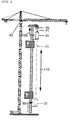
- eine schematische Seitenansicht des erfindungsgemäßen Turmkrans.
-
Figur 1 zeigt einen Querschnitt durch ein einzelnes Gitterelement 10 des erfindungsgemäßen Turmdrehkrans. Der gesamte Turmdrehkran weist einen konventionellen Turmaufstieg 20 auf, der aus einzelnen Leiterelementen 21 besteht. Der Kranbediener kann daher in den Hohlraum des untersten Gitterelementes einsteigen und mittels der Leiteranordnung 21 bis zu der an der Turmspitze angeordneten Krankabine 40 (Figur 2 ) gelangen. Die Platzanforderung des Kranaufstiegs nimmt in etwa zweidrittel der Kranturmquerschnittsfläche in Anspruch. Der Pfeil 22 kennzeichnet den Aufstiegsweg durch die Gitterstücke 10. - In der verbleibenden Querschnittsfläche ist erfindungsgemäß ein Kranfahreraufzug 30 angeordnet, der ergänzend zum konventionellen Kranaufstieg 20 zur Verfügung steht. Der Aufzugsschacht verläuft in der Zeichenebene rechts unten dargestellten Gitterstückecke und vereinnahmt in etwa die Hälfte der verbleibenden Querschnittsfläche.
- Die Kabine 31 des Kranfahreraufzugs 30 gleitet vom Turmfuß 50 bis hin zur Krankabine 40 in vertikaler Richtung (
Figur 2 ). Als Führungsmittel sind zwei Führungsschienen 60 vorgesehen, die an der Innenseite der Gitterstücke parallel zueinander in vertikaler Richtung vom Turmfuß 50 zur Krankabine 31 verlaufen. Die Kabine 31 selbst ist zumindest teilgeschlossen. Der Eintritt erfolgt über einen mechanischen Türmechanismus 32. Zum Öffnen der Zugangstür 32 wird diese in Pfeilrichtung 33 nach innen in die Kabine 31 verschoben. Andere Öffnungsmechanismen sind selbstverständlich möglich und von der Erfindung umfasst. - Zum Antrieb des Kranfahreraufzugs 30 dient ein Seilantrieb, der in an sich bekannter Art und Weise aufgebaut ist. Im Bereich der Turmspitze ist die Seilwinde 70 vorgesehen (
Figur 2 ), das Aufzugseil 71 verläuft von der Aufzugkabine 31 bis hin zur Turmspitze und wird von der Seilwinde 70 auf- bzw. abgewickelt. Alternativ kann die Seilwinde in hier nicht dargestellter Art und Weise auf dem Dach der Aufzugskabine angeordnet sein. - Da die Führungsschienen 60 während des Krantransports an den einzelnen Gitterstücken 10 montiert bleiben, ist es notwendig, dass sich diese in einzelne Führungsteilsegmente untergliedern. Einzelne Teilelemente sind daher an jeder Innenseite der verbauten Gitterstücke montiert.
- Aufgrund gewisser Fertigungstoleranzen der Gitterstücke kann beim Rüsten der einzelnen Gitterstücke ein Versatz zwischen den benachbarten Führungselementen der Führungsschienen 60 auftreten, insbesondere sowohl in vertikaler als auch in horizontaler Richtung. Um zeitaufwendige Nachjustierungen zu vermeiden, lässt man beim Eingriff der Führungsmittel der Kabine 31 in die Führungsschienen 60 ein gewisses Spiel. In Kombination mit dem Seilantrieb ist es möglich, etwaige Versatzstellen zwischen benachbarten Führungselementen problemlos zu überfahren.
- Aus Sicherheitsgründen ist ein Zugangkotrollsystem installiert, um eine Gefährdung der im Kranaufstieg 20 befindlichen Personen durch die Aufzugskabine 31 zu vermeiden.
- Wie der
Figur 1a zu entnehmen ist, kann der Zugang zum Kranaufstieg 20 über eine Türanordnung 80 versperrt bzw. freigegeben werden. Die mechanische Klappbewegung der Tür 80 kann entweder automatisiert oder manuell ausgeführt werden. Ein Türverriegelungsmechanismus zur Ver- und Entriegelung der Tür 80 wird elektronisch durch das Zugangkontrollsystem angesprochen. - Die dargestellte Tür 80 ist in Nähe zum Kranfuss im Eingangsbereich des Kranaufstiegs 20 angeordnet. Gleichzeitig befindet sich in der Turmspitze ebenfalls ein weiteres Türelement 80, das den Zugang zum Kranaufstieg bzw. -abstieg versperrt bzw. freigibt.
- Jedoch muss sichergestellt werden, dass der Zugang 90, 100 zum Kranaufzug 30 durch die angeordnete Tür 80 nicht blockiert wird. Im gezeigten Ausführungsbeispiel ist die Tür 80 daher in vertikaler Richtung oberhalb des Zugangs 90 zum Aufzugsystem 30 angeordnet. Der Kranbediener erhält Zugang zum Kranaufstieg 20 mit Hilfe eines mechanischen Schlüssels. Wird die Tür 80 geöffnet, so blockiert die Kransteuerung automatisch die Stromzufuhr zum Aufzugsystem 30, so dass ein Aufzugbetrieb während des freigegebenen Kranaufstiegs 20 verhindert wird.
- Nach dem Schließen der Tür 80 muss diese zunächst mit Hilfe des Schlüssels verriegelt und anschliessend die Freigabe durch einen Schlüsselschalter erteilt werden. Sobald alle erforderlichen Schritte ordnungsgemäß ausgeführt worden sind, wird die Funktion des Aufzugs 30 wieder freigegeben. Gleiches gilt für den Zugang zum Kranaufstieg 20 an der Oberseite, bei dem der obere Zugang 100 zur Aufzugskabine 31 frei zugänglich ist, der Zugang zum Turmabstieg 20 allerdings gesperrt und nur mittels Schlüssel zu öffnen ist.
- Für Notfälle ist an beiden Türen 80 ein Schlüssel in einem verglasten Kasten zugänglich.
- Zusätzlich kann der Zugang 90, 100 zum Aufzug 30 ebenfalls schlüsselgesichert sein.
- Alternativ oder zusätzlich können eine oder mehrere Leseeinheiten für RFID-Chips an jeder Tür 80 eingebaut sein. Die Person, die den gesicherten Bereich des Kranaufstiegs 20 betreten will, unabhängig davon, ob der Zugang von oben oder unten erfolgt, muss im Besitz eines RFID-Chips sein, der die entsprechenden Daten zur Freigabe der Zugangskontrolle aufweist. Bei Eintritt der Person mit dem RFID-Chip in den Empfangsbereich der Leseeinheiten können die elektronischen Schlüsseldaten des Chips ausgelesen werden und die Freigabe der Türen 80 erteilt werden. Gleiches gilt für den Zugang 90, 100 zur Kabine, der ebenfalls mittels Leseeinheiten kontrolliert sein kann.
Auch in diesem Fall wird die Stromzufuhr für den Kranfahreraufzug 30 unterbrochen, sobald eine der Türen 80 geöffnet bzw. entriegelt ist. Gleichzeitig wird durch die elektronische Zugangskontrolle das tatsächliche Passieren der Tür 80 durch die Person anhand der Chipbewegung erfasst. Dazu sind über den gesamten Kranturm mehrere Leseeinheiten verteilt angeordnet sind, um einen kontinuierlichen Empfang über die gesamte Turmlänge zu ermöglichen. Dieser autorisierte Bereich ist durch den Pfeil 110 gekennzeichnet. Damit kann der Bewegungsverlauf des Chips bzw. der Person nachvollzogen und in der Kransteuerung ausgewertet werden. Erst nach dem Verlassen des gesicherten Bereichs 110 durch die Person mit dem RFID-Chip kann die Tür 80 unten bzw. oben wieder verriegelt werden und die Stromzufuhr zum Kranfahreraufzug 30 reaktiviert werden.
Claims (12)
- Turmkran, insbesondere Turmdrehkran, mit wenigstens einer Krankabine (40), wenigstens einem Kranaufstieg (20) und wenigstens einem Kranfahreraufzug (30), wobei der wenigstens eine Kranfahreraufzug (30) innerhalb des Kranturmquerschnitts angeordnet ist, wobei, der Zugang zu wenigstens einem Kranaufstieg (20) und/oder zu wenigstens einem Kranfahreraufzug (30) durch ein Zugangskontrollsystem gesichert ist, dadurch gekennzeichnet, dass eine Steuerung vorgesehen ist, die in Abhängigkeit des Zugangskontrollsystems wenigstens eines Kranaufstiegs (20) den Antrieb des Kranfahreraufzugs (30) steuert.
- Turmkran nach Anspruch 1, dadurch gekennzeichnet, dass eine oder mehrere Führungsschienen (60) zur Führung des wenigstens einen Kranfahreraufzugs (30) innerhalb des Kranturmquerschnitts angeordnet sind.
- Turmkran nach Anspruch 2, dadurch gekennzeichnet, dass aufzugsseitige Führungsmittel und kranseitige Führungsschienen (60) unter einem gewissen Spiel ineinandergreifen, um Versatzstellen bzw. Unebenheiten der Führungsschienen (60) ausgleichen zu können.
- Turmkran nach einem der vorhergehenden Ansprüche, dadurch gekennzeichnet, dass der wenigstens eine Kranfahreraufzug (30) einen Seilantrieb umfasst.
- Turmkran nach einem der vorhergehenden Ansprüche, dadurch gekennzeichnet, dass der Kranfahreraufzug (30) einen Zahnstangenantrieb umfasst.
- Turmkran nach einem der vorhergehenden Ansprüche, dadurch gekennzeichnet, dass ein oder mehrere Aufnahmen, insbesondere Krallen oder dergleichen, im Kranturmquerschnitt der einzelnen Turmelementen vorgesehen sind, die eine lösbare Befestigung des Kranfahreraufzugs (30) innerhalb des Kranturmquerschnitts erlauben.
- Turmkran nach Anspruch 1, dadurch gekennzeichnet, dass wenigstens ein Kranaufstieg (20) über ein oder mehrere Zugangstüren (80) gesichert ist, insbesondere über je eine Zugangstür (80) am unteren und oberen Kraneinstieg.
- Turmkran nach Anspruch 1, dadurch gekennzeichnet, dass die Steuerung derart ausgeführt ist, so dass diese die Energieversorgung des Kranfahreraufzugs (30) deaktiviert, sobald der Zugang zum Kranaufstieg (20) freigegeben ist.
- Turmkran nach Anspruch 1 oder 8, dadurch gekennzeichnet, dass die Steuerung derart ausgeführt ist, so dass diese die Energieversorgung des Kranfahreraufzugs (30) aktiviert, sobald der Zugang zum Kranaufstieg (20) gesperrt ist.
- Turmkran nach einem der Ansprüche 1 bis 9, dadurch gekennzeichnet, dass die Zugangskontrolle mittels eines mechanischen und/oder elektronischen Schlüssels betätigbar bzw. freigebbar oder sperrbar ist.
- Turmkran nach einem der Ansprüche 1 bis 10, dadurch gekennzeichnet, dass die Zugangskontrolle ein oder mehrere Leseeinheiten für den drahtlosen Empfang elektronischer Schlüsseldaten aufweist, insbesondere basierend auf dem RFID-System, einem LWID-System oder einem ähnlichen Funkübertragungssystem, wobei vorzugsweise eine Empfang über die gesamte Aufstiegslänge sichergestellt ist.
- Turmkran nach einem der Ansprüche 7 bis 11, dadurch gekennzeichnet, dass die Zugangskontrolle derart ausgeführt ist, so dass wahlweise der Zugang zum Aufzugssystem oder zum Kranaufstieg gewährt wird.
Applications Claiming Priority (1)
| Application Number | Priority Date | Filing Date | Title |
|---|---|---|---|
| DE102012020819.7A DE102012020819A1 (de) | 2012-10-23 | 2012-10-23 | Kran |
Publications (2)
| Publication Number | Publication Date |
|---|---|
| EP2724973A1 EP2724973A1 (de) | 2014-04-30 |
| EP2724973B1 true EP2724973B1 (de) | 2018-04-25 |
Family
ID=49484068
Family Applications (1)
| Application Number | Title | Priority Date | Filing Date |
|---|---|---|---|
| EP13005030.5A Active EP2724973B1 (de) | 2012-10-23 | 2013-10-21 | Kran |
Country Status (4)
| Country | Link |
|---|---|
| US (1) | US9809422B2 (de) |
| EP (1) | EP2724973B1 (de) |
| DE (1) | DE102012020819A1 (de) |
| ES (1) | ES2680652T3 (de) |
Cited By (1)
| Publication number | Priority date | Publication date | Assignee | Title |
|---|---|---|---|---|
| DE102018009464A1 (de) | 2018-12-04 | 2020-06-04 | Geda-Dechentreiter Gmbh & Co. Kg | Mast, insbesondere Kranmast für einen Turmdrehkran |
Families Citing this family (8)
| Publication number | Priority date | Publication date | Assignee | Title |
|---|---|---|---|---|
| DE102015107560A1 (de) | 2015-05-13 | 2016-11-17 | USound GmbH | Schallwandleranordnung mit MEMS-Schallwandler |
| CN104973515B (zh) * | 2015-07-05 | 2017-03-08 | 范志甫 | 一种起重机多节安全操作室及其操作方法 |
| CN105271003A (zh) * | 2015-10-28 | 2016-01-27 | 林蓉瑶 | 一种操作方便的塔式起重机 |
| CN106285041A (zh) * | 2016-08-16 | 2017-01-04 | 中国建筑第二工程局有限公司 | 一种塔机反向降塔方法 |
| TWI650282B (zh) * | 2017-06-02 | 2019-02-11 | 國立高雄科技大學 | 安全偵測系統 |
| DE202018101551U1 (de) | 2018-03-20 | 2019-06-25 | Geda-Dechentreiter Gmbh & Co. Kg | Übertritt für einen Aufzug |
| US11964850B2 (en) * | 2019-03-20 | 2024-04-23 | Liebherr-Werk Biberach Gmbh | Crane |
| CN112324793B (zh) * | 2020-11-20 | 2021-12-24 | 安徽博微长安电子有限公司 | 一种伸缩式抗风拉杆机构 |
Family Cites Families (14)
| Publication number | Priority date | Publication date | Assignee | Title |
|---|---|---|---|---|
| US3080981A (en) * | 1961-06-06 | 1963-03-12 | Schwermaschb Kirow Veb | Tower-crane cabin |
| US3627079A (en) * | 1969-10-31 | 1971-12-14 | Norse Dev Corp | Elevator system for mine shaft |
| US3677370A (en) * | 1970-08-19 | 1972-07-18 | Security Systems Inc | Elevator alarm system |
| SE457168B (sv) * | 1985-12-03 | 1988-12-05 | Leif Uno Aake Loftmyr | Anordning vid arbetshytter foer kranar |
| FR2675196B1 (fr) * | 1991-04-12 | 1998-09-04 | Hek France | Echelle de secours avec ascenseur incorpore. |
| DE9107493U1 (de) * | 1991-06-18 | 1992-02-06 | Anton, Rudolf, 7910 Neu-Ulm | Turmdrehkran - Kranführeraufzug mit Fahrkorb |
| FI112068B (fi) * | 1992-12-22 | 2003-10-31 | Kone Corp | Kauko-ohjainliityntä hissijärjestelmään |
| NL1010908C2 (nl) * | 1998-12-28 | 2000-06-30 | Altrex Bv | Liftkooigeleidingsstelsel. |
| DE10025074B4 (de) * | 2000-05-20 | 2006-11-09 | Hailo-Werk Rudolf Loh Gmbh & Co. Kg | Einrichtung zum Befördern von Personen |
| NL1017257C2 (nl) * | 2001-02-01 | 2002-08-02 | Slechtvalk Holding B V | Hijskraan. |
| FI118045B (fi) * | 2005-08-31 | 2007-06-15 | Kone Corp | Menetelmä ja kutsujärjestelmä |
| FR2936236A1 (fr) * | 2008-09-19 | 2010-03-26 | Jean Pierre Teso | Ascenseur d'acces aux postes de travail |
| IT1393937B1 (it) * | 2009-04-09 | 2012-05-17 | Rolic Invest Sarl | Aerogeneratore |
| PT2639193E (pt) * | 2012-03-15 | 2015-02-04 | Manitowoc Crane Group France | Dispositivo de acesso em altura para guindaste de torre |
-
2012
- 2012-10-23 DE DE102012020819.7A patent/DE102012020819A1/de not_active Ceased
-
2013
- 2013-10-21 ES ES13005030.5T patent/ES2680652T3/es active Active
- 2013-10-21 EP EP13005030.5A patent/EP2724973B1/de active Active
- 2013-10-22 US US14/060,395 patent/US9809422B2/en active Active
Non-Patent Citations (1)
| Title |
|---|
| None * |
Cited By (2)
| Publication number | Priority date | Publication date | Assignee | Title |
|---|---|---|---|---|
| DE102018009464A1 (de) | 2018-12-04 | 2020-06-04 | Geda-Dechentreiter Gmbh & Co. Kg | Mast, insbesondere Kranmast für einen Turmdrehkran |
| EP3683178A1 (de) | 2018-12-04 | 2020-07-22 | GEDA-Dechentreiter GmbH & Co. KG. | Mast mit aufzug und personensicherung, insbesondere kranmast für einen turmdrehkran |
Also Published As
| Publication number | Publication date |
|---|---|
| DE102012020819A1 (de) | 2014-05-08 |
| US20140110367A1 (en) | 2014-04-24 |
| EP2724973A1 (de) | 2014-04-30 |
| US9809422B2 (en) | 2017-11-07 |
| ES2680652T3 (es) | 2018-09-10 |
Similar Documents
| Publication | Publication Date | Title |
|---|---|---|
| EP2724973B1 (de) | Kran | |
| EP3007953B1 (de) | Schutzwand für den schutz von personen vor fahrenden schienenfahrzeugen | |
| WO2012126619A1 (de) | Lift mit minimaler schachtkopfhöhe und mit permanentem schutzraum | |
| EP3003944B1 (de) | Aufzugsschacht mit verkleinerter schachtgrube bzw. verkleinertem schachtkopf | |
| EP1930285B1 (de) | Aufzugsanlage mit Sicherheitsvorrichtung an Aufzugstüren | |
| EP2766292B1 (de) | Aufzug | |
| EP2727875A1 (de) | Lift mit Wartungsöffnung im Kabinenboden | |
| EP3186183B1 (de) | Einrichtung zum betätigen einer kabinen- und schachttür einer aufzugsanlage | |
| DE19712646C2 (de) | Seilaufzug | |
| DE2729381A1 (de) | Kletteraufzug | |
| EP2730478A2 (de) | Schienenfahrzeug mit einer Hubliftplattform im Einstiegsbereich | |
| AT517871B1 (de) | Aufzugskabine | |
| EP2172411B1 (de) | Aufzugsanlage mit positionsabhängiger Türsicherung | |
| DE29802089U1 (de) | Bauaufzug | |
| DE102022103676A1 (de) | Fahrkorb mit einer Wartungsöffnung für eine Aufzugsanlage | |
| EP2050703B1 (de) | Aufzuganlage für Personen und/oder Lasten mit zumindest einer Aufzugkabine | |
| DE202011100364U1 (de) | Personen-Schutzsystem | |
| DE29714403U1 (de) | Versorgungseinrichtung für Druckmaschinen mit einem Materiallift | |
| CH702838B1 (de) | Lift, mit geschlossener Kabine im Servicemodus fahrbar. | |
| EP4477835A1 (de) | Tor-system, hebefalt-system und roll-system | |
| EP4434916A1 (de) | Shuttle-system mit einem senkrechtförderer-modul sowie verfahren zum beheben einer störung in einem senkrechtförderer-modul eines shuttle-systems | |
| CH704976A2 (de) | Lift ohne Liftschachtkopf oder mit minimaler Liftschacht-Kopfhöhe und mit permanentem Schutzraum. | |
| EP3683178A1 (de) | Mast mit aufzug und personensicherung, insbesondere kranmast für einen turmdrehkran | |
| CH704628B1 (de) | Lift mit minimaler Liftschacht-Grubentiefe und mit permanentem Schutzraum. | |
| WO2016078943A1 (de) | Bahnhofsbereich umfassend eine versenkbare schutzwand für den schutz von personen vor fahrenden schienenfahrzeugen |
Legal Events
| Date | Code | Title | Description |
|---|---|---|---|
| PUAI | Public reference made under article 153(3) epc to a published international application that has entered the european phase |
Free format text: ORIGINAL CODE: 0009012 |
|
| 17P | Request for examination filed |
Effective date: 20131021 |
|
| AK | Designated contracting states |
Kind code of ref document: A1 Designated state(s): AL AT BE BG CH CY CZ DE DK EE ES FI FR GB GR HR HU IE IS IT LI LT LU LV MC MK MT NL NO PL PT RO RS SE SI SK SM TR |
|
| AX | Request for extension of the european patent |
Extension state: BA ME |
|
| 17P | Request for examination filed |
Effective date: 20141030 |
|
| RAP3 | Party data changed (applicant data changed or rights of an application transferred) |
Owner name: LIEBHERR-WERK BIBERACH GMBH |
|
| 17Q | First examination report despatched |
Effective date: 20170103 |
|
| REG | Reference to a national code |
Ref country code: DE Ref legal event code: R079 Ref document number: 502013009980 Country of ref document: DE Free format text: PREVIOUS MAIN CLASS: B66C0013540000 Ipc: B66C0023260000 |
|
| GRAP | Despatch of communication of intention to grant a patent |
Free format text: ORIGINAL CODE: EPIDOSNIGR1 |
|
| RIC1 | Information provided on ipc code assigned before grant |
Ipc: B66B 9/00 20060101ALI20171031BHEP Ipc: B66C 13/54 20060101ALI20171031BHEP Ipc: B66C 15/00 20060101ALI20171031BHEP Ipc: B66C 23/26 20060101AFI20171031BHEP |
|
| INTG | Intention to grant announced |
Effective date: 20171114 |
|
| GRAJ | Information related to disapproval of communication of intention to grant by the applicant or resumption of examination proceedings by the epo deleted |
Free format text: ORIGINAL CODE: EPIDOSDIGR1 |
|
| GRAP | Despatch of communication of intention to grant a patent |
Free format text: ORIGINAL CODE: EPIDOSNIGR1 |
|
| INTC | Intention to grant announced (deleted) | ||
| GRAA | (expected) grant |
Free format text: ORIGINAL CODE: 0009210 |
|
| GRAS | Grant fee paid |
Free format text: ORIGINAL CODE: EPIDOSNIGR3 |
|
| INTG | Intention to grant announced |
Effective date: 20180313 |
|
| AK | Designated contracting states |
Kind code of ref document: B1 Designated state(s): AL AT BE BG CH CY CZ DE DK EE ES FI FR GB GR HR HU IE IS IT LI LT LU LV MC MK MT NL NO PL PT RO RS SE SI SK SM TR |
|
| REG | Reference to a national code |
Ref country code: GB Ref legal event code: FG4D Free format text: NOT ENGLISH |
|
| REG | Reference to a national code |
Ref country code: CH Ref legal event code: EP Ref country code: CH Ref legal event code: NV Representative=s name: KELLER AND PARTNER PATENTANWAELTE AG, CH |
|
| REG | Reference to a national code |
Ref country code: AT Ref legal event code: REF Ref document number: 992651 Country of ref document: AT Kind code of ref document: T Effective date: 20180515 |
|
| REG | Reference to a national code |
Ref country code: IE Ref legal event code: FG4D Free format text: LANGUAGE OF EP DOCUMENT: GERMAN |
|
| REG | Reference to a national code |
Ref country code: DE Ref legal event code: R096 Ref document number: 502013009980 Country of ref document: DE |
|
| REG | Reference to a national code |
Ref country code: NL Ref legal event code: MP Effective date: 20180425 |
|
| REG | Reference to a national code |
Ref country code: ES Ref legal event code: FG2A Ref document number: 2680652 Country of ref document: ES Kind code of ref document: T3 Effective date: 20180910 Ref country code: LT Ref legal event code: MG4D |
|
| PG25 | Lapsed in a contracting state [announced via postgrant information from national office to epo] |
Ref country code: NL Free format text: LAPSE BECAUSE OF FAILURE TO SUBMIT A TRANSLATION OF THE DESCRIPTION OR TO PAY THE FEE WITHIN THE PRESCRIBED TIME-LIMIT Effective date: 20180425 |
|
| REG | Reference to a national code |
Ref country code: FR Ref legal event code: PLFP Year of fee payment: 6 |
|
| PG25 | Lapsed in a contracting state [announced via postgrant information from national office to epo] |
Ref country code: BG Free format text: LAPSE BECAUSE OF FAILURE TO SUBMIT A TRANSLATION OF THE DESCRIPTION OR TO PAY THE FEE WITHIN THE PRESCRIBED TIME-LIMIT Effective date: 20180725 Ref country code: FI Free format text: LAPSE BECAUSE OF FAILURE TO SUBMIT A TRANSLATION OF THE DESCRIPTION OR TO PAY THE FEE WITHIN THE PRESCRIBED TIME-LIMIT Effective date: 20180425 Ref country code: SE Free format text: LAPSE BECAUSE OF FAILURE TO SUBMIT A TRANSLATION OF THE DESCRIPTION OR TO PAY THE FEE WITHIN THE PRESCRIBED TIME-LIMIT Effective date: 20180425 Ref country code: NO Free format text: LAPSE BECAUSE OF FAILURE TO SUBMIT A TRANSLATION OF THE DESCRIPTION OR TO PAY THE FEE WITHIN THE PRESCRIBED TIME-LIMIT Effective date: 20180725 Ref country code: PL Free format text: LAPSE BECAUSE OF FAILURE TO SUBMIT A TRANSLATION OF THE DESCRIPTION OR TO PAY THE FEE WITHIN THE PRESCRIBED TIME-LIMIT Effective date: 20180425 Ref country code: LT Free format text: LAPSE BECAUSE OF FAILURE TO SUBMIT A TRANSLATION OF THE DESCRIPTION OR TO PAY THE FEE WITHIN THE PRESCRIBED TIME-LIMIT Effective date: 20180425 |
|
| PG25 | Lapsed in a contracting state [announced via postgrant information from national office to epo] |
Ref country code: HR Free format text: LAPSE BECAUSE OF FAILURE TO SUBMIT A TRANSLATION OF THE DESCRIPTION OR TO PAY THE FEE WITHIN THE PRESCRIBED TIME-LIMIT Effective date: 20180425 Ref country code: RS Free format text: LAPSE BECAUSE OF FAILURE TO SUBMIT A TRANSLATION OF THE DESCRIPTION OR TO PAY THE FEE WITHIN THE PRESCRIBED TIME-LIMIT Effective date: 20180425 Ref country code: GR Free format text: LAPSE BECAUSE OF FAILURE TO SUBMIT A TRANSLATION OF THE DESCRIPTION OR TO PAY THE FEE WITHIN THE PRESCRIBED TIME-LIMIT Effective date: 20180726 Ref country code: LV Free format text: LAPSE BECAUSE OF FAILURE TO SUBMIT A TRANSLATION OF THE DESCRIPTION OR TO PAY THE FEE WITHIN THE PRESCRIBED TIME-LIMIT Effective date: 20180425 |
|
| PG25 | Lapsed in a contracting state [announced via postgrant information from national office to epo] |
Ref country code: PT Free format text: LAPSE BECAUSE OF FAILURE TO SUBMIT A TRANSLATION OF THE DESCRIPTION OR TO PAY THE FEE WITHIN THE PRESCRIBED TIME-LIMIT Effective date: 20180827 |
|
| REG | Reference to a national code |
Ref country code: DE Ref legal event code: R097 Ref document number: 502013009980 Country of ref document: DE |
|
| PG25 | Lapsed in a contracting state [announced via postgrant information from national office to epo] |
Ref country code: SK Free format text: LAPSE BECAUSE OF FAILURE TO SUBMIT A TRANSLATION OF THE DESCRIPTION OR TO PAY THE FEE WITHIN THE PRESCRIBED TIME-LIMIT Effective date: 20180425 Ref country code: RO Free format text: LAPSE BECAUSE OF FAILURE TO SUBMIT A TRANSLATION OF THE DESCRIPTION OR TO PAY THE FEE WITHIN THE PRESCRIBED TIME-LIMIT Effective date: 20180425 Ref country code: DK Free format text: LAPSE BECAUSE OF FAILURE TO SUBMIT A TRANSLATION OF THE DESCRIPTION OR TO PAY THE FEE WITHIN THE PRESCRIBED TIME-LIMIT Effective date: 20180425 Ref country code: EE Free format text: LAPSE BECAUSE OF FAILURE TO SUBMIT A TRANSLATION OF THE DESCRIPTION OR TO PAY THE FEE WITHIN THE PRESCRIBED TIME-LIMIT Effective date: 20180425 Ref country code: CZ Free format text: LAPSE BECAUSE OF FAILURE TO SUBMIT A TRANSLATION OF THE DESCRIPTION OR TO PAY THE FEE WITHIN THE PRESCRIBED TIME-LIMIT Effective date: 20180425 |
|
| PG25 | Lapsed in a contracting state [announced via postgrant information from national office to epo] |
Ref country code: SM Free format text: LAPSE BECAUSE OF FAILURE TO SUBMIT A TRANSLATION OF THE DESCRIPTION OR TO PAY THE FEE WITHIN THE PRESCRIBED TIME-LIMIT Effective date: 20180425 |
|
| PLBE | No opposition filed within time limit |
Free format text: ORIGINAL CODE: 0009261 |
|
| STAA | Information on the status of an ep patent application or granted ep patent |
Free format text: STATUS: NO OPPOSITION FILED WITHIN TIME LIMIT |
|
| 26N | No opposition filed |
Effective date: 20190128 |
|
| PG25 | Lapsed in a contracting state [announced via postgrant information from national office to epo] |
Ref country code: SI Free format text: LAPSE BECAUSE OF FAILURE TO SUBMIT A TRANSLATION OF THE DESCRIPTION OR TO PAY THE FEE WITHIN THE PRESCRIBED TIME-LIMIT Effective date: 20180425 |
|
| REG | Reference to a national code |
Ref country code: BE Ref legal event code: MM Effective date: 20181031 |
|
| PG25 | Lapsed in a contracting state [announced via postgrant information from national office to epo] |
Ref country code: MC Free format text: LAPSE BECAUSE OF FAILURE TO SUBMIT A TRANSLATION OF THE DESCRIPTION OR TO PAY THE FEE WITHIN THE PRESCRIBED TIME-LIMIT Effective date: 20180425 Ref country code: LU Free format text: LAPSE BECAUSE OF NON-PAYMENT OF DUE FEES Effective date: 20181021 |
|
| REG | Reference to a national code |
Ref country code: IE Ref legal event code: MM4A |
|
| PG25 | Lapsed in a contracting state [announced via postgrant information from national office to epo] |
Ref country code: BE Free format text: LAPSE BECAUSE OF NON-PAYMENT OF DUE FEES Effective date: 20181031 |
|
| PG25 | Lapsed in a contracting state [announced via postgrant information from national office to epo] |
Ref country code: IE Free format text: LAPSE BECAUSE OF NON-PAYMENT OF DUE FEES Effective date: 20181021 |
|
| PG25 | Lapsed in a contracting state [announced via postgrant information from national office to epo] |
Ref country code: AL Free format text: LAPSE BECAUSE OF FAILURE TO SUBMIT A TRANSLATION OF THE DESCRIPTION OR TO PAY THE FEE WITHIN THE PRESCRIBED TIME-LIMIT Effective date: 20180425 |
|
| PG25 | Lapsed in a contracting state [announced via postgrant information from national office to epo] |
Ref country code: MT Free format text: LAPSE BECAUSE OF FAILURE TO SUBMIT A TRANSLATION OF THE DESCRIPTION OR TO PAY THE FEE WITHIN THE PRESCRIBED TIME-LIMIT Effective date: 20180425 |
|
| PG25 | Lapsed in a contracting state [announced via postgrant information from national office to epo] |
Ref country code: TR Free format text: LAPSE BECAUSE OF FAILURE TO SUBMIT A TRANSLATION OF THE DESCRIPTION OR TO PAY THE FEE WITHIN THE PRESCRIBED TIME-LIMIT Effective date: 20180425 |
|
| PG25 | Lapsed in a contracting state [announced via postgrant information from national office to epo] |
Ref country code: CY Free format text: LAPSE BECAUSE OF FAILURE TO SUBMIT A TRANSLATION OF THE DESCRIPTION OR TO PAY THE FEE WITHIN THE PRESCRIBED TIME-LIMIT Effective date: 20180425 Ref country code: MK Free format text: LAPSE BECAUSE OF NON-PAYMENT OF DUE FEES Effective date: 20180425 Ref country code: HU Free format text: LAPSE BECAUSE OF FAILURE TO SUBMIT A TRANSLATION OF THE DESCRIPTION OR TO PAY THE FEE WITHIN THE PRESCRIBED TIME-LIMIT; INVALID AB INITIO Effective date: 20131021 |
|
| PG25 | Lapsed in a contracting state [announced via postgrant information from national office to epo] |
Ref country code: IS Free format text: LAPSE BECAUSE OF FAILURE TO SUBMIT A TRANSLATION OF THE DESCRIPTION OR TO PAY THE FEE WITHIN THE PRESCRIBED TIME-LIMIT Effective date: 20180825 |
|
| REG | Reference to a national code |
Ref country code: CH Ref legal event code: PFA Owner name: LIEBHERR-WERK BIBERACH GMBH, DE Free format text: FORMER OWNER: LIEBHERR-WERK BIBERACH GMBH, DE |
|
| P01 | Opt-out of the competence of the unified patent court (upc) registered |
Effective date: 20230630 |
|
| PGFP | Annual fee paid to national office [announced via postgrant information from national office to epo] |
Ref country code: GB Payment date: 20241023 Year of fee payment: 12 |
|
| PGFP | Annual fee paid to national office [announced via postgrant information from national office to epo] |
Ref country code: IT Payment date: 20241030 Year of fee payment: 12 Ref country code: ES Payment date: 20241104 Year of fee payment: 12 |
|
| REG | Reference to a national code |
Ref country code: CH Ref legal event code: U11 Free format text: ST27 STATUS EVENT CODE: U-0-0-U10-U11 (AS PROVIDED BY THE NATIONAL OFFICE) Effective date: 20251101 |
|
| PGFP | Annual fee paid to national office [announced via postgrant information from national office to epo] |
Ref country code: DE Payment date: 20251030 Year of fee payment: 13 |
|
| PGFP | Annual fee paid to national office [announced via postgrant information from national office to epo] |
Ref country code: AT Payment date: 20251023 Year of fee payment: 13 |
|
| PGFP | Annual fee paid to national office [announced via postgrant information from national office to epo] |
Ref country code: FR Payment date: 20251024 Year of fee payment: 13 |
|
| PGFP | Annual fee paid to national office [announced via postgrant information from national office to epo] |
Ref country code: CH Payment date: 20251101 Year of fee payment: 13 |