EP2724809A1 - Schweissbrenner - Google Patents
Schweissbrenner Download PDFInfo
- Publication number
- EP2724809A1 EP2724809A1 EP12803182.0A EP12803182A EP2724809A1 EP 2724809 A1 EP2724809 A1 EP 2724809A1 EP 12803182 A EP12803182 A EP 12803182A EP 2724809 A1 EP2724809 A1 EP 2724809A1
- Authority
- EP
- European Patent Office
- Prior art keywords
- collet
- electrode
- welding torch
- electrodes
- contact
- Prior art date
- Legal status (The legal status is an assumption and is not a legal conclusion. Google has not performed a legal analysis and makes no representation as to the accuracy of the status listed.)
- Granted
Links
Images


Classifications
-
- B—PERFORMING OPERATIONS; TRANSPORTING
- B23—MACHINE TOOLS; METAL-WORKING NOT OTHERWISE PROVIDED FOR
- B23K—SOLDERING OR UNSOLDERING; WELDING; CLADDING OR PLATING BY SOLDERING OR WELDING; CUTTING BY APPLYING HEAT LOCALLY, e.g. FLAME CUTTING; WORKING BY LASER BEAM
- B23K9/00—Arc welding or cutting
- B23K9/24—Features related to electrodes
- B23K9/28—Supporting devices for electrodes
- B23K9/29—Supporting devices adapted for making use of shielding means
- B23K9/291—Supporting devices adapted for making use of shielding means the shielding means being a gas
- B23K9/296—Supporting devices adapted for making use of shielding means the shielding means being a gas using non-consumable electrodes
-
- B—PERFORMING OPERATIONS; TRANSPORTING
- B23—MACHINE TOOLS; METAL-WORKING NOT OTHERWISE PROVIDED FOR
- B23K—SOLDERING OR UNSOLDERING; WELDING; CLADDING OR PLATING BY SOLDERING OR WELDING; CUTTING BY APPLYING HEAT LOCALLY, e.g. FLAME CUTTING; WORKING BY LASER BEAM
- B23K35/00—Rods, electrodes, materials, or media, for use in soldering, welding, or cutting
- B23K35/02—Rods, electrodes, materials, or media, for use in soldering, welding, or cutting characterised by mechanical features, e.g. shape
-
- B—PERFORMING OPERATIONS; TRANSPORTING
- B23—MACHINE TOOLS; METAL-WORKING NOT OTHERWISE PROVIDED FOR
- B23K—SOLDERING OR UNSOLDERING; WELDING; CLADDING OR PLATING BY SOLDERING OR WELDING; CUTTING BY APPLYING HEAT LOCALLY, e.g. FLAME CUTTING; WORKING BY LASER BEAM
- B23K35/00—Rods, electrodes, materials, or media, for use in soldering, welding, or cutting
- B23K35/02—Rods, electrodes, materials, or media, for use in soldering, welding, or cutting characterised by mechanical features, e.g. shape
- B23K35/0255—Rods, electrodes, materials, or media, for use in soldering, welding, or cutting characterised by mechanical features, e.g. shape for use in welding
-
- B—PERFORMING OPERATIONS; TRANSPORTING
- B23—MACHINE TOOLS; METAL-WORKING NOT OTHERWISE PROVIDED FOR
- B23K—SOLDERING OR UNSOLDERING; WELDING; CLADDING OR PLATING BY SOLDERING OR WELDING; CUTTING BY APPLYING HEAT LOCALLY, e.g. FLAME CUTTING; WORKING BY LASER BEAM
- B23K35/00—Rods, electrodes, materials, or media, for use in soldering, welding, or cutting
- B23K35/02—Rods, electrodes, materials, or media, for use in soldering, welding, or cutting characterised by mechanical features, e.g. shape
- B23K35/0255—Rods, electrodes, materials, or media, for use in soldering, welding, or cutting characterised by mechanical features, e.g. shape for use in welding
- B23K35/0261—Rods, electrodes or wires
-
- B—PERFORMING OPERATIONS; TRANSPORTING
- B23—MACHINE TOOLS; METAL-WORKING NOT OTHERWISE PROVIDED FOR
- B23K—SOLDERING OR UNSOLDERING; WELDING; CLADDING OR PLATING BY SOLDERING OR WELDING; CUTTING BY APPLYING HEAT LOCALLY, e.g. FLAME CUTTING; WORKING BY LASER BEAM
- B23K35/00—Rods, electrodes, materials, or media, for use in soldering, welding, or cutting
- B23K35/02—Rods, electrodes, materials, or media, for use in soldering, welding, or cutting characterised by mechanical features, e.g. shape
- B23K35/0255—Rods, electrodes, materials, or media, for use in soldering, welding, or cutting characterised by mechanical features, e.g. shape for use in welding
- B23K35/0261—Rods, electrodes or wires
- B23K35/0277—Rods, electrodes or wires of non-circular cross-section
-
- B—PERFORMING OPERATIONS; TRANSPORTING
- B23—MACHINE TOOLS; METAL-WORKING NOT OTHERWISE PROVIDED FOR
- B23K—SOLDERING OR UNSOLDERING; WELDING; CLADDING OR PLATING BY SOLDERING OR WELDING; CUTTING BY APPLYING HEAT LOCALLY, e.g. FLAME CUTTING; WORKING BY LASER BEAM
- B23K35/00—Rods, electrodes, materials, or media, for use in soldering, welding, or cutting
- B23K35/02—Rods, electrodes, materials, or media, for use in soldering, welding, or cutting characterised by mechanical features, e.g. shape
- B23K35/0255—Rods, electrodes, materials, or media, for use in soldering, welding, or cutting characterised by mechanical features, e.g. shape for use in welding
- B23K35/0294—Consumable guides
-
- B—PERFORMING OPERATIONS; TRANSPORTING
- B23—MACHINE TOOLS; METAL-WORKING NOT OTHERWISE PROVIDED FOR
- B23K—SOLDERING OR UNSOLDERING; WELDING; CLADDING OR PLATING BY SOLDERING OR WELDING; CUTTING BY APPLYING HEAT LOCALLY, e.g. FLAME CUTTING; WORKING BY LASER BEAM
- B23K9/00—Arc welding or cutting
- B23K9/16—Arc welding or cutting making use of shielding gas
- B23K9/167—Arc welding or cutting making use of shielding gas and of a non-consumable electrode
- B23K9/1675—Arc welding or cutting making use of shielding gas and of a non-consumable electrode making use of several electrodes
Definitions
- the present invention relates to a welding torch.
- Patent document 1 for example, a multi-electrode type of welding torch that is able to achieve high-speed welding when performing TIG welding is disclosed.
- this type of multi-electrode welding torch is provided with a pair of electrodes that are placed opposite each other on either side of an insulating material, and a collet or the like that fixes these electrodes in position.
- Patent document 1 Japanese Patent Application, First Publication No. 2000-94137
- Patent document 1 a configuration in which the electrodes are formed in a thin plate shape, and the distal ends of the electrodes are formed as pointed tips is employed.
- This configuration has the highly beneficial merit that it makes it possible to weld narrow grooves.
- the electrodes are formed from a tungsten-based material, working the electrodes is problematic, and it is difficult to form the electrodes into thin plates. Because of this, manufacturing costs are high for these electrodes.
- the electrodes are formed from round rods having a circular cross-section, then the electrodes have an arc-shaped curved surface area in at least a portion of their cross-section.
- Power is supplied to an electrode via a metal component known as a collet. If, however, the electrode has an area with a curved surface, then compared with when the electrode is formed in a conventional plate shape having a widened plane, the contact area between the collet and the electrode is reduced, and there is a possibility that the power supply will become unstable.
- the electrode has a plate shape
- the surface of the collet that is able to make contact with the electrode surface has the same plate shape as the electrode surface, a broad surface contact can be ensured.
- the electrode is formed in a rod-shape having a circular cross-section, then because it linearly contacts the plate-shaped collet, there is a decrease in the contact area.
- the present invention was conceived in view of the above-described problems, and it is an object thereof to provide a welding torch that, when electrodes that have curved surface areas in their cross-sectional configuration are used in a multi-electrode welding torch, enables the contact area between the collet and the electrodes to be increased so that power can be supplied stably to the electrodes.
- the present invention employs the following structure as a means of solving the above-described problem.
- a first aspect of the present invention is a welding torch that includes: a plurality of electrodes that are insulated from the welding torch by an insulating material: and collets that are in contact with the electrodes and conduct power to the electrodes, and employs a structure in which the electrodes are shaped such that they have an arc-shaped curved surface area in at least a portion of a cross-sectional shape thereof that is orthogonal to the longitudinal direction thereof, and each collet is provided with a groove portion in which the electrode is fitted, and whose inner wall surface is in contact with a plurality of locations of the curved surface area when looking from the longitudinal direction of the electrode.
- a second aspect of the present invention employs a structure in which, in the above-described first aspect, a notch portion is provided in a distal end of the collet that faces towards a distal end side of the electrode.
- the notch portion it is desirable for the notch portion to be provided in a portion of the distal end of the collet that does not come into contact with the electrode.
- a third aspect of the present invention employs a structure in which, in the above-described first or second aspects, there is provided a collet supporting component that is disposed such that its position is fixed relative to the electrode, and the collet is supported by the collet supporting component such that the collet is able to be tilted relative to the electrode.
- a fourth aspect of the present invention employs a structure in which, in any of the above-described first through third aspects, the collet is supported by the collet supporting component such that the collet can be displaced in a direction that is orthogonal to the longitudinal direction of the electrode.
- a fifth aspect of the present invention employs a structure in which, in any of the above-described first through fourth aspects, the shape of the groove portion when viewed in the longitudinal direction of the electrode is a trapezoidal shape.
- a sixth aspect of the present invention employs a structure in which, in any of the above-described first through fifth aspects, there are provided projecting portions that protrude from inner wall surfaces of the groove portion, and engagement holes that are provided in the electrode and with which the projecting portions engage.
- the collet is provided with a groove portion in which an electrode is fitted, and whose inner wall surfaces are in contact with a plurality of locations of the curved surface area of the electrode when looking from the longitudinal direction of the electrode.
- electrodes that have curved surface areas in their cross-sectional configuration are used in a multi-electrode type of welding torch, it is possible to increase the contact area between the collets and the electrodes, so that power can be supplied stably to the electrodes.
- FIGS. 1A and 1B are schematic structural views of a welding torch 1 of the present embodiment which is used for TIG welding. Note that FIG. 1A is a cross-sectional view on a plane extending along a central axis L, while FIG. 1B is a cross-sectional view taken along a line N-N in FIG. 1A .
- the welding torch 1 shown in FIG. 1A is provided with electrodes 2, insulating material 3, collets 4, a casing 5, and a gas supply portion 6.
- the electrodes 2 are supplied with current from a power supply apparatus (not shown), and generate an arc between themselves and a welding material.
- the welding torch 1 of the present embodiment two electrodes 2 are disposed opposite each other on either side of the insulating material 3. Namely, the welding torch 1 of the present embodiment is provided with a pair of electrodes 2 that are placed on either side of the insulating material 3.
- the electrodes 2 are formed by round rods having a circular cross-section that are made from a tungsten-based material.
- distal end sides of the electrodes 2 are formed into points such that distal endmost portions thereof are positioned on a central axis L side.
- each electrode 2 when viewed from the distal end side, a portion of a circumferential edge of each electrode 2 is cut away so as to form a plane that is parallel with the axis of the electrode 2. As a result, each electrode 2 is provided with a planar portion 2a as a worked portion that is formed by this cutting away.
- the electrodes 2 are disposed such that the planar portions 2a thereof face towards the insulating material 3 side, and the planar portions 2a are in contact with the insulating material 3.
- these electrodes 2 are shaped so as to have an arc-shaped curved surface area R in at least a portion of a cross-sectional configuration thereof that is orthogonal to the longitudinal direction thereof.
- the insulating material 3 is interposed between two of the electrodes 2, and prevents the two electrodes 2 from coming into contact with each other and short-circuiting.
- the shape of the insulating material 3 is such that a cross-section thereof is formed in an I shape.
- the portions of the insulating material 3 that come into contact with the planar portions 2a of the electrodes 2 are formed as planar portions 3a that are in surface contact with the planar portions 2a of the electrodes 2.
- a collet 4 is provided for each one of the electrodes 2, and each collet conducts the current that is supplied from a power supply apparatus (not shown) to the electrode 2.
- Each collet 4 is placed on the outer side of an electrode 2 when viewed from the distal end side of the electrodes 2.
- FIGS. 2A to 2D show the overall structure of a collet 4. Note that FIG. 2A is a view of the collet 4 as seen from the opposite side from the electrode 2, FIG. 2B is a side view of the collet 4, FIG. 2C is a view of the collet 4 as seen from the electrode 2 side, and FIG. 2D is a view of the collet 4 as seen from the rear end side (i.e., the opposite side from the distal end of the electrode 2).
- each collet 4 is formed extending in the longitudinal direction of the electrode 2 and, as is shown in FIGS. 2C and 2D , is provided with a groove portion 4a whose shape as seen from an end surface side of the electrode 2 is trapezoidal.
- the groove portion 4a is formed such that, when the electrode 2 is fitted into the collet 4, the curved surface area R of the electrode 2 is in contact with inner wall surfaces 4b.
- the width and depth of the groove portion 4a are set such that the inner wall surfaces 4b of the grove portion 4a are in contact in two locations with the curved surface area R of the electrode 2.
- a notch portion 4c which is formed by cutting the groove portion 4a in a V-shape that extends towards the opposite side from the distal end, is provided in the distal end of the collet 4 that extends towards the distal end side of the electrode 2.
- the notch portion 4c is provided in a portion of the groove portion 4a that does not come into contact with the electrode 2 when the electrode 2 is fitted into the collet 4.
- Each collet 4 is supported such that it is able to be tilted relative to the electrode 2 around the end thereof that is on the opposite side from the distal end (described below in detail). Because of this, the distal end of the collet 4 is the portion that comes into contact with the electrode 2 with the greatest reliability.
- the notch portion 4c in a part of the distal end of the collet 4 that does not come into contact with the electrode 2, compared with when the notch portion 4c is not provided, the distal end of the collet 4 appears to be lengthened, and the portion that reliably comes into contact with the electrode 2 can be increased.
- This collet 4 is supported by a collet base 7 (i.e., a collet supporting component).
- FIGS. 3A and 3B are cross-sectional views showing a collet 4 and collet base 7 that have been removed from the welding torch. Note that FIG. 3B is a cross-sectional view taken along a line M-M in FIG. 3A . FIG. 4 is a plan view of the collet base 7.
- the collet base 7 is fastened by bolts 9 to an adaptor 8 that is fixed to the casing 5 so that, as a result of this structure, the position of the collet base 7 relative to the electrode 2 is set.
- elongated holes 7a which are elongated in a radial direction, are provided in the collet base 7.
- bolts 10 that are able to move relatively inside the elongated holes 7a in the longitudinal direction of the elongated holes 7a are inserted through the elongated holes 7a, and the collet 4 is fixed to these bolts 10.
- an end of the collet 4 (i.e., the end on the opposite side from the distal end) is positioned such that a slight gap S is provided between itself and the collet base 7.
- the collet 4 is able to be tilted around the end thereof that is on the opposite side from the distal end where the notch portion 4c is provided.
- the collet 4 is fixed to the bolts 10 that are able to move inside the elongated holes 7a that are elongated in the radial direction of the collet base 7, the collet 4 can be displaced in a direction that is orthogonal to the longitudinal direction of the electrode 2.
- the casing 5 surrounds from the outside thereof the portion of the electrodes 2 that does not have the collet 4 and collet base 7 placed outside it, and fixes the collet 4 in position by being placed against the outer circumferential surface of the collet 4.
- the gas supply portion 6 is placed on the distal end side of the welding torch 1, and supplies gas that is used for forming an arc to the distal end of the electrodes 2.
- each collet 4 is provided with a groove portion 4a in which the electrode 2 is fitted, and whose inner wall surfaces 4b are in contact with a plurality of locations (two locations in the present embodiment) of the curved surface area R when looking from the longitudinal direction of the electrode 2.
- the welding torch 1 of the present embodiment in a multi-electrode type of welding torch, it is possible to increase the contact area between the collets 4 and the electrodes 2 when electrodes 2 that have a curved surface area R in the cross-sectional configuration thereof are used, and to thereby ensure a stable supply of power to the electrodes 2.
- the notch portion 4c is provided in the distal end of each collet 4 that points towards the distal end of the electrode 2.
- each collet 4 has the appearance of being lengthened, and it is possible to increase the locations where the collet 4 is in reliable contact with the electrode 2. Accordingly, it is possible to more reliably ensure a stable supply of power to the electrode 2.
- each collet 4 is supported by the collet base 7 such that it is able to be tilted relative to the electrode 2.
- the collet 4 can be tilted such that it is securely in contact with the electrode 2.
- each collet 4 is supported by a collet base 7 such that it is able to be displaced in a direction that is orthogonal to the longitudinal direction of the electrode 2.
- the welding torch 1 of the present embodiment it is possible to prevent the angle of inclination of the collet 4 relative to the electrode 2 from becoming too large, and to guarantee a sufficient size for the contact area between the electrode 2 and the collet 4.
- the groove portions 4a are formed in a trapezoidal shape. Because of this, it is possible to reliably secure two contact locations between the electrodes 2 and the collets 4 while at the same time minimizing the depth of the groove portions 4a.
- the inner wall surfaces 4b of the groove portion 4 are curved surfaces that bulge towards the electrode 2.
- the inner wall surfaces 4b of the groove portion 4 can be made to press firmly against the curved surface area R of the electrode 2, and it is possible to secure an even greater area of contact between the electrode 2 and the collet 4.
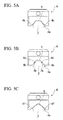
- FIG. 5B it is also possible to employ a structure in which there are provided projecting portions 4d that protrude from the inner wall surfaces 4b of the groove portion 4, and engagement holes 2b that are provided in the curved surface area R of the electrode 2 and with which the projecting portions engage.
- the present invention is not limited to this, and it is also possible to employ a structure in which the electrode 2 and the collet 4 are in contact with each other in an even greater number of contact locations.
- the present invention in a multi-electrode type of welding torch, it is possible to increase the contact area between the collets and the electrodes, and to thereby ensure a stable supply of power to the electrodes.
Landscapes
- Engineering & Computer Science (AREA)
- Mechanical Engineering (AREA)
- Physics & Mathematics (AREA)
- Plasma & Fusion (AREA)
- Arc Welding In General (AREA)
Applications Claiming Priority (2)
| Application Number | Priority Date | Filing Date | Title |
|---|---|---|---|
| JP2011138311 | 2011-06-22 | ||
| PCT/JP2012/065481 WO2012176724A1 (ja) | 2011-06-22 | 2012-06-18 | 溶接トーチ |
Publications (3)
| Publication Number | Publication Date |
|---|---|
| EP2724809A1 true EP2724809A1 (de) | 2014-04-30 |
| EP2724809A4 EP2724809A4 (de) | 2015-05-27 |
| EP2724809B1 EP2724809B1 (de) | 2016-12-14 |
Family
ID=47422561
Family Applications (1)
| Application Number | Title | Priority Date | Filing Date |
|---|---|---|---|
| EP12803182.0A Not-in-force EP2724809B1 (de) | 2011-06-22 | 2012-06-18 | Schweissbrenner |
Country Status (5)
| Country | Link |
|---|---|
| US (1) | US9278405B2 (de) |
| EP (1) | EP2724809B1 (de) |
| JP (1) | JP5720782B2 (de) |
| ES (1) | ES2614870T3 (de) |
| WO (1) | WO2012176724A1 (de) |
Families Citing this family (1)
| Publication number | Priority date | Publication date | Assignee | Title |
|---|---|---|---|---|
| KR102523025B1 (ko) * | 2021-10-20 | 2023-04-18 | 주식회사 성우하이텍 | 스폿 용접용 캡 팁 조립체 |
Family Cites Families (18)
| Publication number | Priority date | Publication date | Assignee | Title |
|---|---|---|---|---|
| GB778963A (en) | 1954-10-22 | 1957-07-17 | Gen Electric Co Ltd | Improvements in or relating to electric welding apparatus |
| FR2361447A1 (fr) | 1976-08-12 | 1978-03-10 | Oreal | Composes colorants constitues de polymeres cationiques hydrosolubles et compositions tinctoriales les contenant |
| JPS5341321U (de) * | 1976-09-13 | 1978-04-10 | ||
| JPS5630458Y2 (de) * | 1976-10-26 | 1981-07-20 | ||
| JPS5360537A (en) | 1976-11-10 | 1978-05-31 | Ardac Inc | Tester for identifying adaptability of certificate |
| BE891916A (fr) | 1981-01-28 | 1982-05-17 | Biotechnolog Forschung Gmbh | Procede d'obtention de cellules hybrides productrices d'un anticorps specifique et procede de production d'anticorps, cellules hybrides et anticorps specifiques ainsi obtenues |
| JPS57194788U (de) * | 1981-06-02 | 1982-12-10 | ||
| JP3027902B2 (ja) | 1994-02-21 | 2000-04-04 | 石川島播磨重工業株式会社 | 多電極溶接ト−チ及び多電極溶接装置 |
| JPH08206839A (ja) * | 1995-02-07 | 1996-08-13 | Masao Miki | 溶接トーチ |
| JP3620136B2 (ja) | 1996-01-25 | 2005-02-16 | 石川島播磨重工業株式会社 | 溶接トーチ |
| JP3629808B2 (ja) * | 1996-04-26 | 2005-03-16 | 石川島播磨重工業株式会社 | 多電極溶接トーチ |
| JP3767101B2 (ja) | 1997-06-27 | 2006-04-19 | 石川島播磨重工業株式会社 | 溶接トーチの電極固定装置 |
| JP4041222B2 (ja) * | 1998-08-28 | 2008-01-30 | 株式会社ダイヘン | Tigアーク溶接ロボット |
| JP3767203B2 (ja) | 1998-09-22 | 2006-04-19 | 石川島播磨重工業株式会社 | Tig溶接トーチ |
| US6683279B1 (en) * | 2001-12-27 | 2004-01-27 | Delford A. Moerke | Twin MIG welding apparatus |
| US7176412B2 (en) * | 2004-03-31 | 2007-02-13 | Tregaskiss Ltd | Taper locking features between components of a welding device |
| US20110297657A1 (en) | 2010-02-04 | 2011-12-08 | Taiko Engineering Co., Ltd. | Contact tip for supplying welding electric power and welding torch using the contact tip |
| US9789560B2 (en) * | 2010-05-12 | 2017-10-17 | Jesse Rogers | Arc welding torch having a variable electrode receiver |
-
2012
- 2012-06-18 US US14/123,674 patent/US9278405B2/en not_active Expired - Fee Related
- 2012-06-18 WO PCT/JP2012/065481 patent/WO2012176724A1/ja not_active Ceased
- 2012-06-18 JP JP2013521571A patent/JP5720782B2/ja active Active
- 2012-06-18 ES ES12803182.0T patent/ES2614870T3/es active Active
- 2012-06-18 EP EP12803182.0A patent/EP2724809B1/de not_active Not-in-force
Also Published As
| Publication number | Publication date |
|---|---|
| EP2724809B1 (de) | 2016-12-14 |
| EP2724809A4 (de) | 2015-05-27 |
| US20140091068A1 (en) | 2014-04-03 |
| JPWO2012176724A1 (ja) | 2015-02-23 |
| WO2012176724A1 (ja) | 2012-12-27 |
| JP5720782B2 (ja) | 2015-05-20 |
| ES2614870T3 (es) | 2017-06-02 |
| US9278405B2 (en) | 2016-03-08 |
Similar Documents
| Publication | Publication Date | Title |
|---|---|---|
| JP5122857B2 (ja) | 電池モジュール及び電池モジュールの接続方法 | |
| JP6176524B2 (ja) | 蓄電装置及び該蓄電装置の製造方法 | |
| US8899888B2 (en) | Tip dresser | |
| WO2016204038A1 (ja) | 抵抗器及びその製造方法 | |
| JP2011249243A (ja) | 電池間接続構造及び接続方法 | |
| EP3364195A1 (de) | Verfahren zur herstellung eines nebenschlusswiderstandes | |
| CN102015176A (zh) | 具有带多个切削刃的切削刀片的切削刀具及其切削刀片 | |
| JP2017501897A (ja) | 割出し可能な中央ドリルインサートおよび切削工具 | |
| WO2019239904A1 (ja) | 蓄電素子モジュール | |
| JP2009087735A (ja) | 端子間接続装置 | |
| JP6148841B2 (ja) | ワッシャ | |
| US9278405B2 (en) | Welding torch | |
| JP6088847B2 (ja) | タブ付き円筒形電池のタブ折り曲げ治具およびタブ付き円筒形電池のタブの折り曲げ加工方法 | |
| CN105873735A (zh) | 钻头 | |
| JP2012240049A (ja) | 溶接トーチ | |
| JP3206961U (ja) | 深くて狭い凹状間隙のためのホットワイヤ溶接アセンブリ | |
| JP2006272472A (ja) | スローアウェイ式ドリル | |
| WO2012008138A1 (ja) | 組電池の製造方法及び組電池 | |
| JP2015198070A (ja) | バスバー付き電池 | |
| JP2016112573A (ja) | シールド溶接用防風フードおよびこの防風フードを用いたガスシールドアーク溶接工法 | |
| JP2015037814A (ja) | 歯切り用回転切削工具 | |
| EP3247009B1 (de) | Verfahren zur herstellung einer rohrförmigen metallhülle mit masseelektrodenstab für eine zündkerze und verfahren zur herstellung einer zündkerze | |
| JP2010123391A (ja) | ジョイント端子および電池セルの接続構造 | |
| JP2017098106A (ja) | ハーネス接続構造及び電池パック | |
| JP6456813B2 (ja) | スパークプラグの製造装置 |
Legal Events
| Date | Code | Title | Description |
|---|---|---|---|
| PUAI | Public reference made under article 153(3) epc to a published international application that has entered the european phase |
Free format text: ORIGINAL CODE: 0009012 |
|
| 17P | Request for examination filed |
Effective date: 20131209 |
|
| AK | Designated contracting states |
Kind code of ref document: A1 Designated state(s): AL AT BE BG CH CY CZ DE DK EE ES FI FR GB GR HR HU IE IS IT LI LT LU LV MC MK MT NL NO PL PT RO RS SE SI SK SM TR |
|
| DAX | Request for extension of the european patent (deleted) | ||
| RA4 | Supplementary search report drawn up and despatched (corrected) |
Effective date: 20150428 |
|
| RIC1 | Information provided on ipc code assigned before grant |
Ipc: B23K 9/29 20060101AFI20150421BHEP Ipc: B23K 35/02 20060101ALI20150421BHEP Ipc: B23K 9/167 20060101ALI20150421BHEP |
|
| GRAP | Despatch of communication of intention to grant a patent |
Free format text: ORIGINAL CODE: EPIDOSNIGR1 |
|
| INTG | Intention to grant announced |
Effective date: 20160621 |
|
| RIN1 | Information on inventor provided before grant (corrected) |
Inventor name: NISHIMURA, YOSHIHITO Inventor name: KOBAYASHI, KAZUYUKI Inventor name: IIJIMA, TOORU Inventor name: MASUMOTO, KAZUO |
|
| GRAS | Grant fee paid |
Free format text: ORIGINAL CODE: EPIDOSNIGR3 |
|
| GRAA | (expected) grant |
Free format text: ORIGINAL CODE: 0009210 |
|
| AK | Designated contracting states |
Kind code of ref document: B1 Designated state(s): AL AT BE BG CH CY CZ DE DK EE ES FI FR GB GR HR HU IE IS IT LI LT LU LV MC MK MT NL NO PL PT RO RS SE SI SK SM TR |
|
| REG | Reference to a national code |
Ref country code: GB Ref legal event code: FG4D |
|
| REG | Reference to a national code |
Ref country code: CH Ref legal event code: EP |
|
| REG | Reference to a national code |
Ref country code: IE Ref legal event code: FG4D |
|
| REG | Reference to a national code |
Ref country code: AT Ref legal event code: REF Ref document number: 853130 Country of ref document: AT Kind code of ref document: T Effective date: 20170115 |
|
| REG | Reference to a national code |
Ref country code: DE Ref legal event code: R096 Ref document number: 602012026685 Country of ref document: DE |
|
| PG25 | Lapsed in a contracting state [announced via postgrant information from national office to epo] |
Ref country code: LV Free format text: LAPSE BECAUSE OF FAILURE TO SUBMIT A TRANSLATION OF THE DESCRIPTION OR TO PAY THE FEE WITHIN THE PRESCRIBED TIME-LIMIT Effective date: 20161214 |
|
| REG | Reference to a national code |
Ref country code: NL Ref legal event code: FP |
|
| REG | Reference to a national code |
Ref country code: LT Ref legal event code: MG4D |
|
| PG25 | Lapsed in a contracting state [announced via postgrant information from national office to epo] |
Ref country code: SE Free format text: LAPSE BECAUSE OF FAILURE TO SUBMIT A TRANSLATION OF THE DESCRIPTION OR TO PAY THE FEE WITHIN THE PRESCRIBED TIME-LIMIT Effective date: 20161214 Ref country code: NO Free format text: LAPSE BECAUSE OF FAILURE TO SUBMIT A TRANSLATION OF THE DESCRIPTION OR TO PAY THE FEE WITHIN THE PRESCRIBED TIME-LIMIT Effective date: 20170314 Ref country code: GR Free format text: LAPSE BECAUSE OF FAILURE TO SUBMIT A TRANSLATION OF THE DESCRIPTION OR TO PAY THE FEE WITHIN THE PRESCRIBED TIME-LIMIT Effective date: 20170315 Ref country code: LT Free format text: LAPSE BECAUSE OF FAILURE TO SUBMIT A TRANSLATION OF THE DESCRIPTION OR TO PAY THE FEE WITHIN THE PRESCRIBED TIME-LIMIT Effective date: 20161214 |
|
| REG | Reference to a national code |
Ref country code: FR Ref legal event code: PLFP Year of fee payment: 6 |
|
| REG | Reference to a national code |
Ref country code: AT Ref legal event code: MK05 Ref document number: 853130 Country of ref document: AT Kind code of ref document: T Effective date: 20161214 |
|
| PG25 | Lapsed in a contracting state [announced via postgrant information from national office to epo] |
Ref country code: RS Free format text: LAPSE BECAUSE OF FAILURE TO SUBMIT A TRANSLATION OF THE DESCRIPTION OR TO PAY THE FEE WITHIN THE PRESCRIBED TIME-LIMIT Effective date: 20161214 Ref country code: HR Free format text: LAPSE BECAUSE OF FAILURE TO SUBMIT A TRANSLATION OF THE DESCRIPTION OR TO PAY THE FEE WITHIN THE PRESCRIBED TIME-LIMIT Effective date: 20161214 Ref country code: FI Free format text: LAPSE BECAUSE OF FAILURE TO SUBMIT A TRANSLATION OF THE DESCRIPTION OR TO PAY THE FEE WITHIN THE PRESCRIBED TIME-LIMIT Effective date: 20161214 |
|
| REG | Reference to a national code |
Ref country code: ES Ref legal event code: FG2A Ref document number: 2614870 Country of ref document: ES Kind code of ref document: T3 Effective date: 20170602 |
|
| PG25 | Lapsed in a contracting state [announced via postgrant information from national office to epo] |
Ref country code: SK Free format text: LAPSE BECAUSE OF FAILURE TO SUBMIT A TRANSLATION OF THE DESCRIPTION OR TO PAY THE FEE WITHIN THE PRESCRIBED TIME-LIMIT Effective date: 20161214 Ref country code: EE Free format text: LAPSE BECAUSE OF FAILURE TO SUBMIT A TRANSLATION OF THE DESCRIPTION OR TO PAY THE FEE WITHIN THE PRESCRIBED TIME-LIMIT Effective date: 20161214 Ref country code: RO Free format text: LAPSE BECAUSE OF FAILURE TO SUBMIT A TRANSLATION OF THE DESCRIPTION OR TO PAY THE FEE WITHIN THE PRESCRIBED TIME-LIMIT Effective date: 20161214 Ref country code: CZ Free format text: LAPSE BECAUSE OF FAILURE TO SUBMIT A TRANSLATION OF THE DESCRIPTION OR TO PAY THE FEE WITHIN THE PRESCRIBED TIME-LIMIT Effective date: 20161214 Ref country code: IS Free format text: LAPSE BECAUSE OF FAILURE TO SUBMIT A TRANSLATION OF THE DESCRIPTION OR TO PAY THE FEE WITHIN THE PRESCRIBED TIME-LIMIT Effective date: 20170414 |
|
| PG25 | Lapsed in a contracting state [announced via postgrant information from national office to epo] |
Ref country code: BG Free format text: LAPSE BECAUSE OF FAILURE TO SUBMIT A TRANSLATION OF THE DESCRIPTION OR TO PAY THE FEE WITHIN THE PRESCRIBED TIME-LIMIT Effective date: 20170314 Ref country code: PT Free format text: LAPSE BECAUSE OF FAILURE TO SUBMIT A TRANSLATION OF THE DESCRIPTION OR TO PAY THE FEE WITHIN THE PRESCRIBED TIME-LIMIT Effective date: 20170414 Ref country code: AT Free format text: LAPSE BECAUSE OF FAILURE TO SUBMIT A TRANSLATION OF THE DESCRIPTION OR TO PAY THE FEE WITHIN THE PRESCRIBED TIME-LIMIT Effective date: 20161214 Ref country code: PL Free format text: LAPSE BECAUSE OF FAILURE TO SUBMIT A TRANSLATION OF THE DESCRIPTION OR TO PAY THE FEE WITHIN THE PRESCRIBED TIME-LIMIT Effective date: 20161214 Ref country code: SM Free format text: LAPSE BECAUSE OF FAILURE TO SUBMIT A TRANSLATION OF THE DESCRIPTION OR TO PAY THE FEE WITHIN THE PRESCRIBED TIME-LIMIT Effective date: 20161214 Ref country code: BE Free format text: LAPSE BECAUSE OF FAILURE TO SUBMIT A TRANSLATION OF THE DESCRIPTION OR TO PAY THE FEE WITHIN THE PRESCRIBED TIME-LIMIT Effective date: 20161214 Ref country code: IT Free format text: LAPSE BECAUSE OF FAILURE TO SUBMIT A TRANSLATION OF THE DESCRIPTION OR TO PAY THE FEE WITHIN THE PRESCRIBED TIME-LIMIT Effective date: 20161214 |
|
| REG | Reference to a national code |
Ref country code: DE Ref legal event code: R097 Ref document number: 602012026685 Country of ref document: DE |
|
| PLBE | No opposition filed within time limit |
Free format text: ORIGINAL CODE: 0009261 |
|
| STAA | Information on the status of an ep patent application or granted ep patent |
Free format text: STATUS: NO OPPOSITION FILED WITHIN TIME LIMIT |
|
| 26N | No opposition filed |
Effective date: 20170915 |
|
| PG25 | Lapsed in a contracting state [announced via postgrant information from national office to epo] |
Ref country code: DK Free format text: LAPSE BECAUSE OF FAILURE TO SUBMIT A TRANSLATION OF THE DESCRIPTION OR TO PAY THE FEE WITHIN THE PRESCRIBED TIME-LIMIT Effective date: 20161214 |
|
| PG25 | Lapsed in a contracting state [announced via postgrant information from national office to epo] |
Ref country code: MC Free format text: LAPSE BECAUSE OF FAILURE TO SUBMIT A TRANSLATION OF THE DESCRIPTION OR TO PAY THE FEE WITHIN THE PRESCRIBED TIME-LIMIT Effective date: 20161214 |
|
| REG | Reference to a national code |
Ref country code: CH Ref legal event code: PL |
|
| PG25 | Lapsed in a contracting state [announced via postgrant information from national office to epo] |
Ref country code: SI Free format text: LAPSE BECAUSE OF FAILURE TO SUBMIT A TRANSLATION OF THE DESCRIPTION OR TO PAY THE FEE WITHIN THE PRESCRIBED TIME-LIMIT Effective date: 20161214 |
|
| REG | Reference to a national code |
Ref country code: IE Ref legal event code: MM4A |
|
| PG25 | Lapsed in a contracting state [announced via postgrant information from national office to epo] |
Ref country code: IE Free format text: LAPSE BECAUSE OF NON-PAYMENT OF DUE FEES Effective date: 20170618 Ref country code: LI Free format text: LAPSE BECAUSE OF NON-PAYMENT OF DUE FEES Effective date: 20170630 Ref country code: LU Free format text: LAPSE BECAUSE OF NON-PAYMENT OF DUE FEES Effective date: 20170618 Ref country code: CH Free format text: LAPSE BECAUSE OF NON-PAYMENT OF DUE FEES Effective date: 20170630 |
|
| REG | Reference to a national code |
Ref country code: FR Ref legal event code: PLFP Year of fee payment: 7 |
|
| PG25 | Lapsed in a contracting state [announced via postgrant information from national office to epo] |
Ref country code: MT Free format text: LAPSE BECAUSE OF NON-PAYMENT OF DUE FEES Effective date: 20170618 |
|
| PG25 | Lapsed in a contracting state [announced via postgrant information from national office to epo] |
Ref country code: HU Free format text: LAPSE BECAUSE OF FAILURE TO SUBMIT A TRANSLATION OF THE DESCRIPTION OR TO PAY THE FEE WITHIN THE PRESCRIBED TIME-LIMIT; INVALID AB INITIO Effective date: 20120618 |
|
| PGFP | Annual fee paid to national office [announced via postgrant information from national office to epo] |
Ref country code: NL Payment date: 20190515 Year of fee payment: 8 |
|
| PGFP | Annual fee paid to national office [announced via postgrant information from national office to epo] |
Ref country code: DE Payment date: 20190604 Year of fee payment: 8 |
|
| PGFP | Annual fee paid to national office [announced via postgrant information from national office to epo] |
Ref country code: FR Payment date: 20190510 Year of fee payment: 8 |
|
| PG25 | Lapsed in a contracting state [announced via postgrant information from national office to epo] |
Ref country code: CY Free format text: LAPSE BECAUSE OF NON-PAYMENT OF DUE FEES Effective date: 20161214 |
|
| PGFP | Annual fee paid to national office [announced via postgrant information from national office to epo] |
Ref country code: GB Payment date: 20190612 Year of fee payment: 8 Ref country code: ES Payment date: 20190702 Year of fee payment: 8 |
|
| PG25 | Lapsed in a contracting state [announced via postgrant information from national office to epo] |
Ref country code: MK Free format text: LAPSE BECAUSE OF FAILURE TO SUBMIT A TRANSLATION OF THE DESCRIPTION OR TO PAY THE FEE WITHIN THE PRESCRIBED TIME-LIMIT Effective date: 20161214 |
|
| PG25 | Lapsed in a contracting state [announced via postgrant information from national office to epo] |
Ref country code: TR Free format text: LAPSE BECAUSE OF FAILURE TO SUBMIT A TRANSLATION OF THE DESCRIPTION OR TO PAY THE FEE WITHIN THE PRESCRIBED TIME-LIMIT Effective date: 20161214 |
|
| PG25 | Lapsed in a contracting state [announced via postgrant information from national office to epo] |
Ref country code: AL Free format text: LAPSE BECAUSE OF FAILURE TO SUBMIT A TRANSLATION OF THE DESCRIPTION OR TO PAY THE FEE WITHIN THE PRESCRIBED TIME-LIMIT Effective date: 20161214 |
|
| REG | Reference to a national code |
Ref country code: DE Ref legal event code: R119 Ref document number: 602012026685 Country of ref document: DE |
|
| REG | Reference to a national code |
Ref country code: NL Ref legal event code: MM Effective date: 20200701 |
|
| GBPC | Gb: european patent ceased through non-payment of renewal fee |
Effective date: 20200618 |
|
| PG25 | Lapsed in a contracting state [announced via postgrant information from national office to epo] |
Ref country code: GB Free format text: LAPSE BECAUSE OF NON-PAYMENT OF DUE FEES Effective date: 20200618 Ref country code: FR Free format text: LAPSE BECAUSE OF NON-PAYMENT OF DUE FEES Effective date: 20200630 Ref country code: NL Free format text: LAPSE BECAUSE OF NON-PAYMENT OF DUE FEES Effective date: 20200701 |
|
| PG25 | Lapsed in a contracting state [announced via postgrant information from national office to epo] |
Ref country code: DE Free format text: LAPSE BECAUSE OF NON-PAYMENT OF DUE FEES Effective date: 20210101 |
|
| REG | Reference to a national code |
Ref country code: ES Ref legal event code: FD2A Effective date: 20211103 |
|
| PG25 | Lapsed in a contracting state [announced via postgrant information from national office to epo] |
Ref country code: ES Free format text: LAPSE BECAUSE OF NON-PAYMENT OF DUE FEES Effective date: 20200619 |