EP2724196B1 - Projector with flexible printed circuit board for the light source - Google Patents
Projector with flexible printed circuit board for the light source Download PDFInfo
- Publication number
- EP2724196B1 EP2724196B1 EP12737619.2A EP12737619A EP2724196B1 EP 2724196 B1 EP2724196 B1 EP 2724196B1 EP 12737619 A EP12737619 A EP 12737619A EP 2724196 B1 EP2724196 B1 EP 2724196B1
- Authority
- EP
- European Patent Office
- Prior art keywords
- housing
- light source
- section
- circuit board
- printed circuit
- Prior art date
- Legal status (The legal status is an assumption and is not a legal conclusion. Google has not performed a legal analysis and makes no representation as to the accuracy of the status listed.)
- Active
Links
- 230000003014 reinforcing effect Effects 0.000 claims description 24
- 230000003287 optical effect Effects 0.000 claims description 16
- 239000004020 conductor Substances 0.000 claims description 4
- 239000004973 liquid crystal related substance Substances 0.000 description 44
- 239000000758 substrate Substances 0.000 description 12
- 238000010586 diagram Methods 0.000 description 9
- 230000009467 reduction Effects 0.000 description 5
- 238000005452 bending Methods 0.000 description 4
- 230000005540 biological transmission Effects 0.000 description 4
- 230000006866 deterioration Effects 0.000 description 4
- 230000001413 cellular effect Effects 0.000 description 3
- 239000002184 metal Substances 0.000 description 3
- 229910052751 metal Inorganic materials 0.000 description 3
- 230000007812 deficiency Effects 0.000 description 2
- 238000005401 electroluminescence Methods 0.000 description 2
- 238000004519 manufacturing process Methods 0.000 description 2
- 230000010287 polarization Effects 0.000 description 2
- RYGMFSIKBFXOCR-UHFFFAOYSA-N Copper Chemical compound [Cu] RYGMFSIKBFXOCR-UHFFFAOYSA-N 0.000 description 1
- 239000004642 Polyimide Substances 0.000 description 1
- XUIMIQQOPSSXEZ-UHFFFAOYSA-N Silicon Chemical compound [Si] XUIMIQQOPSSXEZ-UHFFFAOYSA-N 0.000 description 1
- 230000008901 benefit Effects 0.000 description 1
- 239000003086 colorant Substances 0.000 description 1
- 230000006835 compression Effects 0.000 description 1
- 238000007906 compression Methods 0.000 description 1
- 229910052802 copper Inorganic materials 0.000 description 1
- 239000010949 copper Substances 0.000 description 1
- 230000000694 effects Effects 0.000 description 1
- 239000011521 glass Substances 0.000 description 1
- 239000000463 material Substances 0.000 description 1
- 239000011159 matrix material Substances 0.000 description 1
- 230000004048 modification Effects 0.000 description 1
- 238000012986 modification Methods 0.000 description 1
- 238000000059 patterning Methods 0.000 description 1
- 229920001721 polyimide Polymers 0.000 description 1
- 229910052710 silicon Inorganic materials 0.000 description 1
- 239000010703 silicon Substances 0.000 description 1
- 239000000126 substance Substances 0.000 description 1
- 239000010409 thin film Substances 0.000 description 1
Images


Classifications
-
- G—PHYSICS
- G03—PHOTOGRAPHY; CINEMATOGRAPHY; ANALOGOUS TECHNIQUES USING WAVES OTHER THAN OPTICAL WAVES; ELECTROGRAPHY; HOLOGRAPHY
- G03B—APPARATUS OR ARRANGEMENTS FOR TAKING PHOTOGRAPHS OR FOR PROJECTING OR VIEWING THEM; APPARATUS OR ARRANGEMENTS EMPLOYING ANALOGOUS TECHNIQUES USING WAVES OTHER THAN OPTICAL WAVES; ACCESSORIES THEREFOR
- G03B21/00—Projectors or projection-type viewers; Accessories therefor
- G03B21/14—Details
- G03B21/20—Lamp housings
- G03B21/2006—Lamp housings characterised by the light source
- G03B21/2033—LED or laser light sources
-
- G—PHYSICS
- G03—PHOTOGRAPHY; CINEMATOGRAPHY; ANALOGOUS TECHNIQUES USING WAVES OTHER THAN OPTICAL WAVES; ELECTROGRAPHY; HOLOGRAPHY
- G03B—APPARATUS OR ARRANGEMENTS FOR TAKING PHOTOGRAPHS OR FOR PROJECTING OR VIEWING THEM; APPARATUS OR ARRANGEMENTS EMPLOYING ANALOGOUS TECHNIQUES USING WAVES OTHER THAN OPTICAL WAVES; ACCESSORIES THEREFOR
- G03B21/00—Projectors or projection-type viewers; Accessories therefor
- G03B21/14—Details
- G03B21/20—Lamp housings
- G03B21/2073—Polarisers in the lamp house
-
- H—ELECTRICITY
- H04—ELECTRIC COMMUNICATION TECHNIQUE
- H04N—PICTORIAL COMMUNICATION, e.g. TELEVISION
- H04N9/00—Details of colour television systems
- H04N9/12—Picture reproducers
- H04N9/31—Projection devices for colour picture display, e.g. using electronic spatial light modulators [ESLM]
- H04N9/3141—Constructional details thereof
- H04N9/315—Modulator illumination systems
-
- H—ELECTRICITY
- H04—ELECTRIC COMMUNICATION TECHNIQUE
- H04N—PICTORIAL COMMUNICATION, e.g. TELEVISION
- H04N9/00—Details of colour television systems
- H04N9/12—Picture reproducers
- H04N9/31—Projection devices for colour picture display, e.g. using electronic spatial light modulators [ESLM]
- H04N9/3141—Constructional details thereof
- H04N9/3173—Constructional details thereof wherein the projection device is specially adapted for enhanced portability
-
- F—MECHANICAL ENGINEERING; LIGHTING; HEATING; WEAPONS; BLASTING
- F21—LIGHTING
- F21V—FUNCTIONAL FEATURES OR DETAILS OF LIGHTING DEVICES OR SYSTEMS THEREOF; STRUCTURAL COMBINATIONS OF LIGHTING DEVICES WITH OTHER ARTICLES, NOT OTHERWISE PROVIDED FOR
- F21V19/00—Fastening of light sources or lamp holders
- F21V19/001—Fastening of light sources or lamp holders the light sources being semiconductors devices, e.g. LEDs
- F21V19/003—Fastening of light source holders, e.g. of circuit boards or substrates holding light sources
-
- F—MECHANICAL ENGINEERING; LIGHTING; HEATING; WEAPONS; BLASTING
- F21—LIGHTING
- F21V—FUNCTIONAL FEATURES OR DETAILS OF LIGHTING DEVICES OR SYSTEMS THEREOF; STRUCTURAL COMBINATIONS OF LIGHTING DEVICES WITH OTHER ARTICLES, NOT OTHERWISE PROVIDED FOR
- F21V19/00—Fastening of light sources or lamp holders
- F21V19/04—Fastening of light sources or lamp holders with provision for changing light source, e.g. turret
-
- H—ELECTRICITY
- H05—ELECTRIC TECHNIQUES NOT OTHERWISE PROVIDED FOR
- H05K—PRINTED CIRCUITS; CASINGS OR CONSTRUCTIONAL DETAILS OF ELECTRIC APPARATUS; MANUFACTURE OF ASSEMBLAGES OF ELECTRICAL COMPONENTS
- H05K1/00—Printed circuits
- H05K1/18—Printed circuits structurally associated with non-printed electric components
- H05K1/189—Printed circuits structurally associated with non-printed electric components characterised by the use of a flexible or folded printed circuit
-
- H—ELECTRICITY
- H05—ELECTRIC TECHNIQUES NOT OTHERWISE PROVIDED FOR
- H05K—PRINTED CIRCUITS; CASINGS OR CONSTRUCTIONAL DETAILS OF ELECTRIC APPARATUS; MANUFACTURE OF ASSEMBLAGES OF ELECTRICAL COMPONENTS
- H05K2201/00—Indexing scheme relating to printed circuits covered by H05K1/00
- H05K2201/10—Details of components or other objects attached to or integrated in a printed circuit board
- H05K2201/10007—Types of components
- H05K2201/10106—Light emitting diode [LED]
Definitions
- the present invention relates to a projector.
- a projector including a light source device, a light modulating device that modulates a light beam emitted from the light source device, and a projection optical device that projects the light beam modulated by the light modulating device (see, for example, PTL 1).
- an LED (Light Emitting Diode) light source is adopted rather than a light source lamp of a discharge type.
- This LED light source includes a configuration in which a light emitting device (a light emitting section) is mounted on an LED circuit board.
- the light modulating device (a liquid crystal device) is electrically connected to, via a flexible printed circuit board, a control board that controls the operations of the light modulating device and the LED light source.
- a signal is output from the control board via the flexible printed circuit board, whereby the light modulating device is controlled.
- a connector provided on the LED circuit board and the control board are connected by the flexible printed circuit board and a signal is output from the control board via the flexible printed circuit board, whereby the LED light source is controlled.
- PTL 2 discloses a projector comprising a light source device, a light-modulating device for modulating a light beam emitted from the light source device, and a projection optical device which projects the light beam modulated by the light modulating device. These items are contained within a housing.
- a flexible PCB connects LC panels, which are used as the light-modulating device, to the signal electronics.
- PTL3 describes a projector comprising a light source device, a light-modulating device for modulating a light beam emitted from the light source device, and a projection optical device which projects the light beam modulated by the light modulating device.
- an LC display device comprises a LED light source on a PCB.
- the LED light source is connected to the LC panel via a U-shaped flexible printed circuit board.
- the projector described in PTL 1 has a problem in that connecting paths between the control board and the light modulating device and between the control board and the LED light source are two paths (two flexible printed circuit boards) independent from each other and the reduction in the size of the projector is prevented by wiring of the two paths.
- the projector when configured as a pico-projector (also referred to as micro-projector or nano-projector in some case) used together with an electronic device (e.g., incorporated in the electronic device) such as a digital camera, a cellular phone, or a notebook PC (Personal Computer), it is difficult to design the projector to a desired thickness dimension.
- a pico-projector also referred to as micro-projector or nano-projector in some case
- an electronic device e.g., incorporated in the electronic device
- a digital camera e.g., a digital camera, a cellular phone, or a notebook PC (Personal Computer)
- notebook PC Personal Computer
- An advantage of some aspects of the invention is to provide a projector that can be reduced in size.
- An aspect of the invention is directed to a projector as defined in independent claim 1.
- the light source device includes the light emitting device and is mounted on the flexible printed circuit board, the one end of which is connected to the light modulating device.
- the projector when configured as a pico-projector, the projector is suitable because it is possible to design the projector to a sufficiently small desired size.
- a mounting board an LED circuit board
- a flexible printed circuit board for connecting the mounting board and the control board
- a connector to which the flexible printed circuit board is connected. Therefore, since the number of components is reduced, it is possible to realize a further reduction in the size of the projector and reduce manufacturing costs for the projector.
- the flexible printed circuit board is bent, whereby the light source device is disposed in an emission position where the light source device emits the light beam to the light modulating device.
- the light source device can be disposed in the emission position simply by bending the flexible printed circuit board connected to the light modulating device. Therefore, it is possible to easily carry out assembly of the projector.
- the projector of the aspect of the invention includes a housing in which the light source device, the light modulating device, and the projection optical device are housed.
- a positioning protrusion for positioning the light source device in the emission position is formed on the housing.
- the flexible printed circuit board includes a positioning hole in which the positioning protrusion is fitted. The positioning protrusion fits in the positioning hole to position the light source device in the emission position.
- the positioning protrusion is formed on the housing and the positioning hole is formed on the flexible printed circuit board. Therefore, simply by fitting the positioning protrusion in the positioning hole, it is possible to easily position the light source device in the emission position while simplifying the structure of the projector.
- the positioning protrusion is formed on the outer surface of the housing.
- An insert-through section for drawing around the flexible printed circuit board to the outside of the housing is formed in the housing.
- the flexible printed circuit board is drawn around to the outside of the housing via the insert-through section.
- a portion between the positioning hole and the one end is bent along the outer surface of the housing.
- the flexible printed circuit board is drawn around to the outside of the housing via the insert-through section.
- the portion between the positioning hole and the connecting position of the light modulating device is bent along the outer surface of the housing.
- the positioning protrusion is formed on the outer surface of the housing.
- a screw hole in which a screw is screwed and an insert-through section for drawing around the flexible printed circuit board to the outside of the housing are formed.
- the flexible printed circuit board includes a first fixing hole through which the screw is inserted.
- the projector includes a second fixing hole through which the screw is inserted and a holding member connected to the housing by the screw and configured to hold a part of the flexible printed circuit board between the holding member and the outer surface of the housing.
- the projector since the projector includes the holding member and holds a part of the flexible printed circuit board between the holding member and the outer surface of the housing, it is possible to satisfactorily maintain a fit state of the positioning protrusion in the positioning hole, i.e., satisfactorily maintain a positioned state of the light source device in the emission position.
- the holding member is made of a thermally conductive material and is connected to the light source device via the flexible printed circuit board to be capable of transmitting heat.
- the holding member is configured as explained above, it is possible to radiate heat generated by lighting driving for the light source device to the outside through a heat transmission path from the light source device to the flexible printed circuit board (patterned wiring) and the holding member while satisfactorily maintaining a positioned state of the light source device in the emission position. Therefore, it is possible to effectively suppress heat deterioration of the light source device.
- the flexible printed circuit board is formed such that the width dimension of a portion where the light source device is mounted is larger than the width dimension of the other portions.
- the flexible printed circuit board is configured as explained above, it is possible to increase a heat capacity of the portion where the light source device is mounted compared with the other portions. Therefore, it is possible to effectively radiate heat generated by lighting driving for the light source device to the portion and effectively suppress heat deterioration of the light source device.
- the projector of the aspect of the invention includes a housing in which the light source device, the light modulating device, and the projection optical device are housed.
- a housing in which the light source device, the light modulating device, and the projection optical device are housed.
- an insert-through section for drawing around the flexible printed circuit board to the outside of the housing is formed.
- the housing includes a first housing section and a second housing section formed separate from each other and combined with each other.
- the light modulating device is disposed in a connecting position of the first housing section and the second housing section.
- the insert-through section is formed by combining the first housing section and the second housing section.
- the insert-through section is formed in the position where the light modulating device is disposed in the housing. Therefore, it is possible to draw around the flexible printed circuit board to the outside of the housing via the insert-through section.
- the insert-through section is formed by combining the first and second housing sections.
- an illuminating system such as the light source device is housed in the first housing section and the projection optical device is housed in the second housing section, in a state in which the light source device and the like are housed in the housing, it is possible to easily carry out adjustment (optical axis adjustment) of a positional relation between the illuminating system such as the light source device and the projection optical device.
- the projector of the aspect of the invention includes a connecting member configured to integrate the first housing section and the second housing section.
- the projector since the projector includes the connecting member, even if the housing includes the first and second housing sections formed separate from each other, it is possible to integrate the first and second housing sections using the connecting member and increase the strength of the housing.
- the housing is formed to have a substantially rectangular parallelepiped shape by combining the first housing section and the second housing section.
- the connecting member includes a connecting member body attached to a first side surface of the housing to extend over the connecting position and a reinforcing section configured to project from the connecting member body and disposed to be opposed to a second side surface different from the first side surface in the housing to extend over the connecting position.
- the connecting member since the connecting member includes the connecting member body and the reinforcing section, it is possible to effectively increase the strength of the housing by reinforcing the housing with the connecting member body and the reinforcing section from the sides of the different two surfaces (the first and second side surfaces) of the housing to extend over the connecting position where strength is low.
- the insert-through section is formed on the second side surface.
- the insert-through section is formed on the second side surface.
- a positioning protrusion for positioning the light source device in the emission position and a screw hole in which a screw is fitted are formed on the outer surface of the housing.
- the flexible printed circuit board includes a first fixing hole through which the screw is inserted and a positioning hole in which the positioning protrusion is fitted.
- the positioning protrusion is fitted in the positioning hole to position the light source device in the emission position.
- the connecting member includes a second fixing hole through which the screw is inserted and a holding member connected to the housing by the screw and configured to hold a part of the flexible substrate between the holding member and the outer surface of the housing.
- the connecting member includes a function (the holding member) of maintaining a positioned state of the light source device in the emission position while including a function (the connecting member body and the reinforcing section) of increasing the strength of the housing.
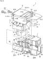
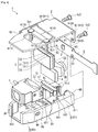
- Figs. 1 to 4 are diagrams showing the configuration of a projector 1 in this embodiment.
- Fig. 1 is a perspective view of the projector 1 viewed from the top surface side (the upper side).
- Fig. 2 is a perspective view of the projector 1 viewed from the bottom surface side (the lower side).
- Figs. 3 and 4 are disassembled perspective views of the projector 1 viewed from the upper side.
- the projector 1 projects an image and displays the projected image on a screen (not shown in the figures).
- the projector 1 in this embodiment is configured as a small optical module (a pico-projector) mounted on an electronic device (not shown in the figures) such as a digital camera, a cellular phone, or a notebook PC.
- a small optical module a pico-projector mounted on an electronic device (not shown in the figures) such as a digital camera, a cellular phone, or a notebook PC.
- the projector 1 includes a light source device 2 ( Figs. 3 and 4 ), first and second lenses 3A and 3B ( Figs. 3 and 4 ), a polarizing beam splitter 4 ( Figs. 3 and 4 ), a liquid crystal panel 5 functioning as a light modulating device, a flexible printed circuit board (hereinafter, FPC) 6, a projection lens 7 functioning as a projection optical device, a housing 8, and a connecting member 9.
- a light source device 2 Figs. 3 and 4
- first and second lenses 3A and 3B Figs. 3 and 4
- a polarizing beam splitter 4 Figs. 3 and 4
- a liquid crystal panel 5 functioning as a light modulating device
- FPC flexible printed circuit board
- projection lens 7 functioning as a projection optical device
- housing 8 a housing 8
- a light beam emitted from the light source device 2 is, after being converted into substantially parallel beams by the first and second lenses 3A and 3B, converted into linearly polarized light of practically one kind by the polarizing beam splitter 4.
- the light beam (the linearly polarized light) converted by the polarizing beam splitter 4 is, after being modulated by the liquid crystal panel 5, projected on a screen (not shown in the figures) by the projection lens 7.
- Configuration of the light source device, the liquid crystal panel, and the FPC Fig. 5 is a diagram for explaining the configuration of the light source device 2, the liquid crystal panel 5, and the FPC 6.
- the liquid crystal panel 5 modulates an incident light beam under the control by a control board (not shown in the figure) provided on the inside of the electronic device.
- the liquid crystal panel 5 includes a transmissive liquid crystal panel including a panel body 51, an incident side polarizer 52, and an emission side polarizer 53.
- the panel body 51 includes a configuration in which liquid crystal, which is an electro-optical substance, is hermetically sealed in a pair of substrates 511 and 512 having a rectangular shape in plan view made of glass or the like.
- the substrate 511 of the pair of substrates 511 and 512 is a driving substrate for driving the liquid crystal.
- the substrate 511 includes plural data lines formed to be arrayed in parallel to one another, plural scanning lines formed to be arrayed in a direction orthogonal to the plural data lines, pixel electrodes formed to be arrayed in a matrix shape to correspond to crossing of the scanning lines and the data lines, a switching device such as a TFT (Thin Film Transistor), and a driving circuit that drives the switching device.
- TFT Thin Film Transistor
- the substrate 512 is an opposed substrate arranged to be opposed to the substrate 511 at a predetermined space therefrom on a light incident side of the substrate 511.
- the substrate 512 includes a common electrode to which a predetermined voltage Vcom is applied.
- a signal is input to the substrate 512 from the control board via the FPC 6 (a signal line for driving of the liquid crystal panel 5), whereby a voltage is applied between a predetermined one of the pixel electrodes and the common electrode, an oriented state of the liquid crystal interposed between the pixel electrode and the common electrode is controlled, and an incident light beam is modulated.
- the incident side polarizer 52 is attached to a light incident surface of the panel body 51.
- the incident side polarizer 52 transmits only predetermined linearly polarized light (linearly polarized light converted by the polarizing beam splitter 4).
- the emission side polarizer 53 is attached to a light emission surface of the panel body 51.
- the emission side polarizer 53 transmits only linearly polarized light having a polarization direction orthogonal to a polarization direction of the linearly polarized light converted by the polarizing beam splitter 4.
- the FPC 6 is formed by, for example, patterning a signal wire (the signal line for driving of the liquid crystal panel 5, a power supply line for supplying electric power to the light source device 2, a signal line for lighting control for the light source device 2, etc.) on a base material of polyimide or the like.
- the FPC 6 electrically connects the control board to the liquid crystal panel 5 and the light source device 2.
- one end side of the FPC 6 is electrically connected to, by compression bonding or the like, an external circuit connection terminal (not shown in the figures) formed near an end of the liquid crystal panel 5.
- a connector (not shown in the figures) is provided on the other end side of the FPC 6.
- the FPC 6 is electrically connected to the control board via the connector.
- a positioning structure for positioning the light source device 2 (hereinafter, the positioning structure for the light source device 2) is provided in an emission position for emitting a light beam to the liquid crystal panel 5.
- the positioning structure is explained below.
- the light source device 2 includes an LED functioning as a light-emitting device and is mounted on the FPC 6.
- Electric power for lighting is supplied to the light source device 2 from the control board via the power supply line (not shown in the figure) formed on the FPC 6.
- a signal is input to the light source device 2 from the control board via the signal line for lighting control for the light source device 2 formed on the FPC 6. In this way, the light source device 2 is subjected to lighting control.
- the light source device 2 In the housing 8, the light source device 2, the first and second lenses 3A and 3B, the polarizing beam splitter 4, the liquid crystal panel 5, and the projection lens 7 are housed.
- the housing 8 is configured to linearly dispose the light source device 2, the first and second lenses 3A and 3B, the polarizing beam splitter 4, the liquid crystal panel 5, and the projection lens 7.
- the housing 8 includes a first housing section 81 and a second housing section 82 formed separate from each other.
- the housing 8 is formed to have a substantially rectangular parallelepiped shape by combining the first and second housing sections 81 and 82 with each other.
- first side surface 8U a surface on the upper side
- second side surface 8L a surface on the left side viewed from a projection side in Figs. 3 and 4
- third side surface 8D a surface on the lower side
- fourth side surface 8R a surface on the right side viewed from the projection side in Figs. 3 and 4
- fifth side surface 8P a surface opposed to the fifth side surface 8P is referred to as sixth side surface 8B.
- the housing 8 is formed in a container shape having a first opening 8U1 on the first side surface 8U.
- the first housing section 81 is a section in which the light source device 2, the first and second lenses 3A and 3B, and the polarizing beam splitter 4 are housed.
- plural grooves 811 are formed in the first housing section 81, on the inner surface, as shown in Fig. 3 or 4 .
- the plural grooves 811 are used for sliding the first and second lenses 3A and 3B and the polarizing beam splitter 4 from the first side surface 8U side to and disposing the first and second lenses 3A and 3B and the polarizing beam splitter 4 on the inside of the first housing section 81.
- an opening for light source 812 is formed in the first housing section 81, on the sixth side surface 8B, as shown in Figs. 3 or 4 .
- the opening for light source 812 communicates with the inside and the outside of the first housing section 81, communicates with the first opening 8U1 as well, and is used for disposing the light source device 2 on the inside of the first housing section 81.
- the positioning structure for the light source device 2 is provided on the sixth side surface 8B in the first housing section 81.
- the positioning structure is explained below.
- the second housing section 82 is a section in which the projection lens 7 is housed.
- a pair of first screw holes 821 are formed in order to connect the second housing section 82 and the connecting member 9.
- a pair of first fixing screws Sc1 are respectively screwed.
- an opening for passage 822 is formed in the second housing section 82, on the fifth side surface 8P, as shown in Fig. 3 or 4 .
- the opening for passage 822 communicates with the inside and the outside of the second housing section 82, communicates with the first opening 8U1 as well, and is used for allowing a light beam projected by the projection lens 7 to pass.
- the liquid crystal panel 5 is disposed between the first and second housing sections 81 and 82 (a connecting position of the first and second housing sections 81 and 82) via a sheet metal member 10 ( Figs. 3 and 4 ) explained below.
- a first insert-through section 8L1 for drawing around the FPC 6 to the outside of the housing 8 is formed.
- a second insert-through section 8D1 through which a part of the liquid crystal panel 5 is inserted is formed.
- the first and second housing sections 81 and 82 are set such that ends thereof on the second side surface 8L side separate a predetermined space from each other.
- the separating portions function as the first insert-through section 8L1 explained above.
- the sheet metal member 10 is a member formed such that a first plate section 11 and a second plate section 12 having a tabular shape are parallel to each other while having a step therebetween.
- the first plate section 11 is held between the polarizing beam splitter 4 and the bottom of the first housing section 81 in a state in which the polarizing beam splitter 4 is housed in the first housing section 81.
- the second plate section 12 is drawn out to the outside of the housing 8 via the second insert-through section 8D1.
- the liquid crystal panel 5 is placed and fixed on the second plate section 12.
- a part of the liquid crystal panel 5 projects from the first opening 8U1 in a state in which the liquid crystal panel 5 is housed in the housing 8 via the sheet metal member 10.
- apart of the liquid crystal panel 5 inserted through the second insert-through section 8D1 is substantially flush with the third side surface 8D.
- the connecting member 9 is a member that is connected to the first and second housing sections 81 and 82 and integrates the first and second housing sections 81 and 82. As shown in Fig. 3 or 4 , the connecting member 9 includes a connecting member body 91 and a reinforcing section 92.
- the connecting member body 91 includes a tabular lid section 911 having a planar shape substantially the same as the shape of the first side surface 8U of the housing 8 and a tabular light source connecting section 912 having a planar shape substantially the same as the shape of the sixth side surface 8B of the housing 8.
- the lid section 911 functions as a lid body that comes into contact with the first side surface 8U and closes the first opening 8U1 in a state in which the connecting member 9 is connected to the housing 8.
- a second opening 911A having a substantially rectangular shape is formed in the lid section 911.
- the part of the liquid crystal panel 5 projecting from the first opening 8U1 is inserted through the second opening 911A in a state in which the connecting member 9 is connected to the housing 8.
- a pair of fixing holes 911 B are formed in order to connect the second housing section 82 and the connecting member 9.
- the pair of first fixing screws Sc1 are respectively inserted through the pair of fixing holes 911B.
- a substantially rectangular opening for lens 911C is formed in a position corresponding to a disposed position of the projection lens 7, as shown in Fig. 1 , 3 , or 4 .
- the opening for lens 911C is used for exposing a part of the projection lens 7 to the outside in a state in which the connecting member 9 is connected to the housing 8.
- the light source connecting section 912 substantially vertically hangs down from the end edge on the sixth side surface 8B side in the lid section 911 and holds the FPC 6 between the light source connecting section 912 and the sixth side surface 8B in a state in which the connecting member 9 is connected to the housing 8.
- the light source connecting section 912 corresponds to the holding member according to the invention.
- the positioning structure for the light source device 2 is provided in the light source connecting section 912, as in the FPC 6 and the first housing section 81. However, the positioning structure is explained below.
- the reinforcing section 92 includes a rectangular plate member substantially vertically hanging down from the end edge on the second side surface 8L side in the lid section 911. As shown in Fig. 1 or 2 , the reinforcing section 92 is disposed to be opposed to the second side surface 8L at a predetermined space therefrom to extend over a connecting position of the first and second housing sections 81 and 82 in a state in which the connecting member 9 is connected to the housing 8.
- the connecting member 9 explained above is formed of a thermally conductive material such as copper.
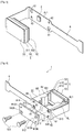
- Fig. 6 is a diagram for explaining the positioning structure for the light source device 2. Specifically, Fig. 6 is a disassembled perspective view of the first housing section 81, the FPC 6, and the light source connecting section 912 viewed from the sixth side surface 8B side.
- the width dimension of an area (an area arranged to be opposed to the sixth side surface 8B) Ar1 including a mounting position C where the light source device 2 is mounted is set substantially the same as the height dimension (the dimension in the up down direction in Fig. 6 ) of the sixth side surface 8B and set to be larger than the width dimension of the other areas.
- a pair of first fixing holes 61 are formed to be opposed to each other centering around the mounting position C.
- a pair of second fixing screws Sc2 are respectively screwed.
- a pair of first positioning holes 62 are formed in a position avoiding the pair of first fixing holes 61 to be opposed to each other centering around the mounting position C.
- a positioning structure provided in the first housing section 81 is explained.
- a pair of second screw holes 813 are formed in order to connect the first housing section 81 and the connecting member 9.
- the pair of second fixing screws Sc2 are respectively screwed.
- a pair of positioning protrusions 814 are formed on the sixth side surface 8B.
- the pair of positioning protrusions 814 respectively fit in the pair of first positioning holes 62.
- a positioning structure provided in the light source connecting section 912 is explained.
- a pair of second fixing holes 912A are formed in order to connect the connecting member 9 and the first housing section 81.
- the pair of second fixing screws Sc2 are respectively inserted through the pair of second fixing holes 912A.
- a pair of second positioning holes 912B are formed in the light source connecting section 912.
- the pair of positioning protrusions 814 respectively fit in the pair of second positioning holes 912B.
- the light source device 2 is positioned in the emission position for emitting a light beam to the liquid crystal panel 5.
- the FPC 6 is drawn around from the second side surface 8L side of the housing 8 to the outside via the first insert-through section 8L1.
- the FPC 6 is bent about 90 degrees to the sixth side surface 8B side along the second side surface 8L of the first housing section 81 and further bent about 90 degrees to the fourth side surface 8R side along the sixth side surface 8B.
- the pair of positioning protrusions 814 of the first housing section 81 are fit in the pair of positioning holes 62 of the FPC 6, whereby the light source device 2 is positioned in the emission position.
- the portion between the pair of first positioning holes 62 and the one end connected to the liquid crystal panel 5 is bent along the outer surface of the housing 8 as explained above.
- the pair of second positioning holes 912B of the light source connecting section 912 are fit in the pair of positioning protrusions 814 of the first housing section 81.
- the first and second fixing screws Sc1 and Sc2 are screwed in the first and second screw holes 821 and 813 via the holes 911B, 912A, and 61.
- the first and second fixing screws Sc1 and Sc2 are screwed in this way, whereby the first and second housing sections 81 and 82 are integrated by the connecting member 9 and the area Ar1 is held between the sixth side surface 8B of the first housing section 81 and the light source connecting section 912.
- the light source connecting section 912 is connected to the light source device 2 via the area Ar1 (patterned wiring) of the FPC 6 to be capable of transmitting heat.
- a part of the liquid crystal panel 5 projecting from the first opening 8U1 is substantially flush with the upper surface of the lid section 911.
- the light source device 2 includes an LED and is mounted on the FPC 6, one end of which is connected to the liquid crystal panel 5.
- the projector 1 is configured as a pico-projector. Therefore, the projector 1 is suitable because it is possible to design the projector 1 to a sufficiently small desired size.
- the FPC 6 is bent, whereby the light source device 2 is disposed in an emission position where the light source device 2 emits a light beam to the liquid crystal panel 5.
- the light source device 2 can be disposed in the emission position simply by bending the FPC 6. Therefore, it is possible to easily carry out assembly of the projector 1.
- the positioning protrusions 814 are formed on the housing 8 and the first positioning holes 62 are formed on the FPC 6, simply by fitting the positioning protrusions 814 in the first positioning holes 62, it is possible to easily position the light source device 2 in the emission position while simplifying the structure of the projector 1.
- the FPC 6 is drawn around to the outside of the housing 8 via the first insert-through section 8L1 and the portion between the first positioning holes 62 and the one end connected to the liquid crystal panel 5 is bent along the outer surface of the housing 8.
- the projector 1 includes the light source connecting section 912 and the area Ar1 of the FPC 6 is held between the light source connecting section 912 and the outer surface of the housing 8. Therefore, it is possible to more satisfactorily maintain the fit state of the positioning protrusions 814 in the first positioning holes 62, i.e., more satisfactorily maintain the positioned state of the light source device 2 in the emission position.
- the area Ar1 of the FPC 6 is held between the tabular light source connecting section 912 and the outer surface (the sixth side surface 8B formed by a plane) of the housing 8, it is possible to improve the flatness of the area Ar1 Therefore, it is possible to set an emitting direction of a light beam from the light source device 2 in a desired direction while satisfactorily maintaining the positioned state of the light source device 2 in the emission position.
- the light source connecting section 912 is made of a thermally conductive material and connected to the light source device 2 via the area Ar1 of the FPC 6 to be capable of transmitting heat.
- the FPC 6 is formed such that the width dimension of the area Ar1 is large compared with the width dimension of the other portions. In other words, it is possible to increase the heat capacity of the area Ar1 where the light source device 2 is mounted compared with the other areas. Therefore, it is possible to effectively radiate heat generated by lighting driving for the light source device 2 to the area Ar1 and further transmit the heat from the area Ar1 to the light source connecting section 912. Therefore, it is possible to effectively suppress heat deterioration of the light source device 2.
- the second opening 911A is formed in the lid section 911. Therefore, it is possible to suppress heat transmitted to the lid section 911 from being transmitted to the liquid crystal panel 5 through the heat transmission path from the light source device 2 to the FPC 6 and the light source connecting section 912.
- the reinforcing section 92 is disposed to be opposed to the second side surface 8L at a predetermined space therefrom. Therefore, it is possible to prevent the reinforcing section 92 from being connected to the FPC 6, which is bent along the second side surface 8L, to be capable of transmitting heat and suppress heat transmitted to the reinforcing section 92 from being transmitted to the FPC 6 through the heat transmission path from the light source device 2 to the FPC 6 and the light source connecting section 912.
- the first and second insert-through sections 8L1 and 8D1 are formed by combining the first and second housing sections 81 and 82.
- the illuminating systems 2, 3A, 3B, and 4 are housed in the first housing section 81 and the projection lens 7 is housed in the second housing section 82, it is possible to easily carry out adjustment (optical axis adjustment) of a positional relation between the illuminating systems 2, 3A, 3B, and 4 and the projection lens 7 in a state in which these optical components are housed in the housing 8.
- the projector 1 includes the connecting member 9, even if the housing 8 includes the first and second housing sections 81 and 82 formed separate from each other, it is possible to integrate the first and second housing sections 81 and 82 using the connecting member 9 and increase the strength of the housing 8.
- the connecting member 9 includes the connecting member body 91 and the reinforcing section 92, it is possible to effectively increase the strength of the housing 8 by reinforcing the housing 8 with the connecting member body 91 and the reinforcing section 92 from the sides of the different two surfaces (the first and second side surfaces 8U and 8L) to extend over the connecting position of the first and second housing sections 81 and 82 where strength is low.
- the first insert-through section 8L1 is formed on the second side surface 8L. In other words, when the FPC 6 is drawn around to the outside of the housing 8 via the first insert-through section 8L1, the FPC 6 is drawn around to the side where the reinforcing section 92 is disposed.
- the FPC 6 bent along the outer surface of the housing 8 is protected by the reinforcing section 92 and the light source connecting section 912.
- the connecting member 9 includes a function (the light source connecting section 912) of maintaining the positioned state of the light source device 2 in the emission position while including a function (the the lid section 911 and the reinforcing section 92) of increasing the strength of the housing 8.
- the liquid crystal panel 5 includes a transmissive liquid crystal panel.
- the liquid crystal panel 5 is not limited to this and may include a reflective liquid crystal panel.
- color filters may be provided as appropriate to display three colors of red (R), green (G), and blue (B) for each of pixels and form a color image.
- the housing 8 includes the two members of the first and second housing sections 81 and 82 formed separate from each other.
- the housing 8 is not limited to this and may include one member.
- the light source device 2 includes the LED.
- the light source device 2 is not limited to this and may adopt another light emitting device such as a laser diode, an organic EL (Electro Luminescence) device, or a silicon light emitting device.
- the invention can be applied in a projector including a light source device, a light modulating device that modulates a light beam emitted from the light source device, and a projection optical device that projects the light beam modulated by the light modulating device.
Landscapes
- Physics & Mathematics (AREA)
- General Physics & Mathematics (AREA)
- Engineering & Computer Science (AREA)
- Multimedia (AREA)
- Signal Processing (AREA)
- Optics & Photonics (AREA)
- Liquid Crystal (AREA)
- Projection Apparatus (AREA)
- Transforming Electric Information Into Light Information (AREA)
Applications Claiming Priority (3)
| Application Number | Priority Date | Filing Date | Title |
|---|---|---|---|
| JP2011138236 | 2011-06-22 | ||
| JP2012056945A JP5990948B2 (ja) | 2011-06-22 | 2012-03-14 | プロジェクター |
| PCT/JP2012/003860 WO2012176404A1 (en) | 2011-06-22 | 2012-06-13 | Projector with flexible printed circuit board for the light source |
Publications (2)
| Publication Number | Publication Date |
|---|---|
| EP2724196A1 EP2724196A1 (en) | 2014-04-30 |
| EP2724196B1 true EP2724196B1 (en) | 2016-04-13 |
Family
ID=46545845
Family Applications (1)
| Application Number | Title | Priority Date | Filing Date |
|---|---|---|---|
| EP12737619.2A Active EP2724196B1 (en) | 2011-06-22 | 2012-06-13 | Projector with flexible printed circuit board for the light source |
Country Status (7)
| Country | Link |
|---|---|
| US (1) | US9442353B2 (enExample) |
| EP (1) | EP2724196B1 (enExample) |
| JP (1) | JP5990948B2 (enExample) |
| CN (1) | CN102841491B (enExample) |
| BR (1) | BR112013033199A2 (enExample) |
| RU (1) | RU2014101720A (enExample) |
| WO (1) | WO2012176404A1 (enExample) |
Families Citing this family (13)
| Publication number | Priority date | Publication date | Assignee | Title |
|---|---|---|---|---|
| GB2501535A (en) * | 2012-04-26 | 2013-10-30 | Sony Corp | Chrominance Processing in High Efficiency Video Codecs |
| US10132485B2 (en) | 2014-02-14 | 2018-11-20 | Crosman Corporation | Deterrent device attachment having light source with thermal management |
| JP2017003744A (ja) | 2015-06-09 | 2017-01-05 | セイコーエプソン株式会社 | 光学デバイスおよび画像表示装置 |
| JP6520432B2 (ja) * | 2015-06-09 | 2019-05-29 | セイコーエプソン株式会社 | 光学デバイスおよび画像表示装置 |
| CN204929444U (zh) * | 2015-06-30 | 2015-12-30 | 鸿富锦精密工业(武汉)有限公司 | 投影仪 |
| CN110277722A (zh) * | 2018-03-16 | 2019-09-24 | 青岛海信激光显示股份有限公司 | 一种激光器的封装组件、光源模组及激光投影机 |
| JP7167628B2 (ja) * | 2018-10-29 | 2022-11-09 | 日本電信電話株式会社 | 光源分離方法、光源分離装置および光源分離プログラム |
| US11532277B2 (en) * | 2019-03-26 | 2022-12-20 | Sharp Kabushiki Kaisha | Display device having a plurality of data lines for driving a plurality of display regions |
| CN110161793A (zh) * | 2019-04-16 | 2019-08-23 | 苏州佳世达光电有限公司 | 一种投影调整系统、投影机及支撑机构 |
| CN112904650A (zh) | 2019-11-19 | 2021-06-04 | 青岛海信激光显示股份有限公司 | 激光投影设备 |
| CN112824967B (zh) * | 2019-11-19 | 2022-04-26 | 青岛海信激光显示股份有限公司 | 激光投影设备 |
| CN112349309A (zh) * | 2020-11-05 | 2021-02-09 | 杭州职业技术学院 | 一种数字媒体播放装置用的防护装置 |
| CN113703264B (zh) * | 2021-09-08 | 2022-09-27 | 昆山智盛精密铸造有限公司 | 一种投影仪壳体压铸件及其压铸工艺 |
Family Cites Families (35)
| Publication number | Priority date | Publication date | Assignee | Title |
|---|---|---|---|---|
| JP2534057B2 (ja) * | 1987-04-24 | 1996-09-11 | タマパツク株式会社 | 携帯式投影装置 |
| JP3130733B2 (ja) * | 1994-07-13 | 2001-01-31 | シャープ株式会社 | 液晶表示装置及びそれを用いたプロジェクタ |
| JP3261928B2 (ja) * | 1995-05-22 | 2002-03-04 | 松下電器産業株式会社 | 液晶ユニット投光装置 |
| JP3798475B2 (ja) | 1996-08-02 | 2006-07-19 | シチズン電子株式会社 | 液晶表示装置 |
| JP2000227605A (ja) | 1998-11-30 | 2000-08-15 | Optrex Corp | 液晶表示装置 |
| JP3645761B2 (ja) | 1999-10-15 | 2005-05-11 | Necアクセステクニカ株式会社 | Lcdバックライト |
| JP2002006313A (ja) | 2000-06-22 | 2002-01-09 | Nec Corp | 液晶表示装置 |
| JP2002182205A (ja) | 2000-12-15 | 2002-06-26 | Sharp Corp | 液晶表示装置 |
| JP2003090993A (ja) * | 2001-09-19 | 2003-03-28 | Kawaguchiko Seimitsu Co Ltd | 液晶表示装置用バックライト構造 |
| JP3864862B2 (ja) | 2002-04-04 | 2007-01-10 | セイコーエプソン株式会社 | 電気光学装置及び電子機器 |
| JP2004004581A (ja) | 2002-04-04 | 2004-01-08 | Seiko Epson Corp | 放熱部材、照明装置、電気光学装置及び電子機器 |
| JP4349557B2 (ja) | 2002-11-29 | 2009-10-21 | オプトレックス株式会社 | 液晶表示装置 |
| TWI294976B (en) * | 2003-08-18 | 2008-03-21 | Seiko Epson Corp | Method for controlling optical control device, optical control device, spatial light modulation device, and projector |
| JP4543772B2 (ja) | 2003-09-19 | 2010-09-15 | セイコーエプソン株式会社 | 電気光学装置および電子機器 |
| JP4461869B2 (ja) | 2004-03-25 | 2010-05-12 | セイコーエプソン株式会社 | 電気光学装置及び電子機器 |
| US7714931B2 (en) * | 2004-06-25 | 2010-05-11 | Flextronics International Usa, Inc. | System and method for mounting an image capture device on a flexible substrate |
| JP4239944B2 (ja) | 2004-09-28 | 2009-03-18 | セイコーエプソン株式会社 | プロジェクタ、及びプロジェクタ等に用いられる偏光部材 |
| TWI245158B (en) * | 2004-10-08 | 2005-12-11 | Premier Image Technology Corp | An image projector having a led light source |
| JP4306590B2 (ja) | 2004-11-05 | 2009-08-05 | セイコーエプソン株式会社 | 電気光学装置及び電子機器 |
| JP2006178138A (ja) * | 2004-12-22 | 2006-07-06 | Seiko Epson Corp | プロジェクタ |
| JP2007292924A (ja) * | 2006-04-24 | 2007-11-08 | Seiko Epson Corp | 光学装置、および当該光学装置を備えたプロジェクタ |
| JP2007323017A (ja) * | 2006-06-05 | 2007-12-13 | Hitachi Displays Ltd | 液晶表示装置 |
| JP4432937B2 (ja) * | 2006-06-06 | 2010-03-17 | セイコーエプソン株式会社 | 電気光学装置、及びこれを備えた電子機器 |
| JP2007333773A (ja) * | 2006-06-12 | 2007-12-27 | Seiko Epson Corp | プロジェクタ |
| CN101155475B (zh) * | 2006-09-28 | 2010-09-22 | 精工爱普生株式会社 | 基板制造方法、控制基板和投影仪 |
| JP2008116875A (ja) * | 2006-11-08 | 2008-05-22 | Seiko Epson Corp | 液晶装置及びプロジェクタ |
| BRPI0721020A2 (pt) | 2007-01-22 | 2014-07-29 | Sharp Kk | Dispositivo de luz traseira e visor plano usando o mesmo |
| JP2008216537A (ja) * | 2007-03-02 | 2008-09-18 | Nikon Corp | プロジェクタ装置 |
| JP2009025602A (ja) * | 2007-07-20 | 2009-02-05 | Citizen Electronics Co Ltd | 液晶セル接着用両面粘着テープ及びバックライトユニット及び液晶表示装置及び液晶表示装置の製造方法 |
| JP5245502B2 (ja) | 2008-04-09 | 2013-07-24 | 株式会社ニコン | プロジェクタモジュールの実装構造および電子機器 |
| TWI382565B (zh) * | 2008-10-15 | 2013-01-11 | 揚明光學股份有限公司 | 發光二極體裝置及應用該裝置的光學引擎 |
| CN201429765Y (zh) * | 2009-04-15 | 2010-03-24 | 深圳高迪数码有限公司 | Lcos投影机led散热结构 |
| JP5584433B2 (ja) | 2009-06-17 | 2014-09-03 | 株式会社ジャパンディスプレイ | 液晶表示装置 |
| FR2950673B1 (fr) * | 2009-09-30 | 2011-12-09 | Valeo Vision | Support pour source lumineuse de module d'eclairage |
| DE102009045919A1 (de) | 2009-10-22 | 2011-04-28 | Robert Bosch Gmbh | Mikromechanische Projektionsvorrichtung sowie Verfahren zum Herstellen einer mikromechanischen Projektionsvorrichtung |
-
2012
- 2012-03-14 JP JP2012056945A patent/JP5990948B2/ja active Active
- 2012-06-13 BR BR112013033199A patent/BR112013033199A2/pt not_active Application Discontinuation
- 2012-06-13 WO PCT/JP2012/003860 patent/WO2012176404A1/en not_active Ceased
- 2012-06-13 EP EP12737619.2A patent/EP2724196B1/en active Active
- 2012-06-13 RU RU2014101720/28A patent/RU2014101720A/ru not_active Application Discontinuation
- 2012-06-13 US US14/124,552 patent/US9442353B2/en active Active
- 2012-06-18 CN CN201210204348.3A patent/CN102841491B/zh active Active
Also Published As
| Publication number | Publication date |
|---|---|
| US20140104585A1 (en) | 2014-04-17 |
| BR112013033199A2 (pt) | 2017-12-12 |
| US9442353B2 (en) | 2016-09-13 |
| EP2724196A1 (en) | 2014-04-30 |
| CN102841491A (zh) | 2012-12-26 |
| CN102841491B (zh) | 2015-07-08 |
| JP2013029799A (ja) | 2013-02-07 |
| JP5990948B2 (ja) | 2016-09-14 |
| WO2012176404A1 (en) | 2012-12-27 |
| RU2014101720A (ru) | 2015-07-27 |
Similar Documents
| Publication | Publication Date | Title |
|---|---|---|
| EP2724196B1 (en) | Projector with flexible printed circuit board for the light source | |
| JP2013029799A5 (enExample) | ||
| US8212961B2 (en) | Backlight for liquid crystal display device having a first FPCB mounting a plurality of light emitting diodes connecting a second FPCB via a through hole formed on a lower cover | |
| KR101804892B1 (ko) | 발광다이오드어셈블리 및 그를 포함한 액정표시장치 | |
| US8721159B2 (en) | Lighting device, display device and television receiver | |
| US20120293728A1 (en) | Lighting device, display device and television receiver | |
| US9274268B2 (en) | Lighting device, display device, and television device | |
| EP2816407B1 (en) | Projector with thermally conductive member surrounding its housing | |
| KR101722625B1 (ko) | 백라이트 유닛 및 이를 이용한 액정표시장치 | |
| US8752996B2 (en) | Lighting device, display device and television receiver | |
| KR20170100750A (ko) | 인쇄회로기판 연결구조 및 이를 갖는 디스플레이 장치 | |
| KR101687783B1 (ko) | 액정표시장치 | |
| KR101803911B1 (ko) | 액정표시장치 | |
| WO2014141882A1 (ja) | 表示装置、及びテレビ受信装置 | |
| JP5879767B2 (ja) | プロジェクター | |
| US9581846B2 (en) | Display device and television device | |
| JP5754260B2 (ja) | プロジェクター | |
| KR101875724B1 (ko) | 액정표시장치 | |
| WO2010103703A1 (ja) | 照明装置、表示装置、及びテレビ受信装置 | |
| JP7027220B2 (ja) | 表示装置及び連結表示装置 | |
| KR20050014944A (ko) | 액정표시장치 | |
| KR20120044194A (ko) | 액정표시장치 모듈 | |
| KR20160038933A (ko) | 액정표시장치 모듈 | |
| KR20060126073A (ko) | 백라이트 어셈블리 및 이를 구비한 표시 장치 | |
| JP2020047546A (ja) | 照明装置、表示装置、および、テレビ受信装置 |
Legal Events
| Date | Code | Title | Description |
|---|---|---|---|
| PUAI | Public reference made under article 153(3) epc to a published international application that has entered the european phase |
Free format text: ORIGINAL CODE: 0009012 |
|
| 17P | Request for examination filed |
Effective date: 20140122 |
|
| AK | Designated contracting states |
Kind code of ref document: A1 Designated state(s): AL AT BE BG CH CY CZ DE DK EE ES FI FR GB GR HR HU IE IS IT LI LT LU LV MC MK MT NL NO PL PT RO RS SE SI SK SM TR |
|
| DAX | Request for extension of the european patent (deleted) | ||
| GRAJ | Information related to disapproval of communication of intention to grant by the applicant or resumption of examination proceedings by the epo deleted |
Free format text: ORIGINAL CODE: EPIDOSDIGR1 |
|
| GRAP | Despatch of communication of intention to grant a patent |
Free format text: ORIGINAL CODE: EPIDOSNIGR1 |
|
| INTG | Intention to grant announced |
Effective date: 20151016 |
|
| INTG | Intention to grant announced |
Effective date: 20151102 |
|
| GRAS | Grant fee paid |
Free format text: ORIGINAL CODE: EPIDOSNIGR3 |
|
| GRAA | (expected) grant |
Free format text: ORIGINAL CODE: 0009210 |
|
| AK | Designated contracting states |
Kind code of ref document: B1 Designated state(s): AL AT BE BG CH CY CZ DE DK EE ES FI FR GB GR HR HU IE IS IT LI LT LU LV MC MK MT NL NO PL PT RO RS SE SI SK SM TR |
|
| REG | Reference to a national code |
Ref country code: GB Ref legal event code: FG4D |
|
| REG | Reference to a national code |
Ref country code: AT Ref legal event code: REF Ref document number: 790760 Country of ref document: AT Kind code of ref document: T Effective date: 20160415 Ref country code: CH Ref legal event code: EP |
|
| REG | Reference to a national code |
Ref country code: IE Ref legal event code: FG4D |
|
| REG | Reference to a national code |
Ref country code: DE Ref legal event code: R096 Ref document number: 602012017052 Country of ref document: DE |
|
| REG | Reference to a national code |
Ref country code: FR Ref legal event code: PLFP Year of fee payment: 5 |
|
| REG | Reference to a national code |
Ref country code: LT Ref legal event code: MG4D |
|
| REG | Reference to a national code |
Ref country code: AT Ref legal event code: MK05 Ref document number: 790760 Country of ref document: AT Kind code of ref document: T Effective date: 20160413 |
|
| REG | Reference to a national code |
Ref country code: NL Ref legal event code: MP Effective date: 20160413 |
|
| PG25 | Lapsed in a contracting state [announced via postgrant information from national office to epo] |
Ref country code: PL Free format text: LAPSE BECAUSE OF FAILURE TO SUBMIT A TRANSLATION OF THE DESCRIPTION OR TO PAY THE FEE WITHIN THE PRESCRIBED TIME-LIMIT Effective date: 20160413 Ref country code: FI Free format text: LAPSE BECAUSE OF FAILURE TO SUBMIT A TRANSLATION OF THE DESCRIPTION OR TO PAY THE FEE WITHIN THE PRESCRIBED TIME-LIMIT Effective date: 20160413 Ref country code: NL Free format text: LAPSE BECAUSE OF FAILURE TO SUBMIT A TRANSLATION OF THE DESCRIPTION OR TO PAY THE FEE WITHIN THE PRESCRIBED TIME-LIMIT Effective date: 20160413 Ref country code: LT Free format text: LAPSE BECAUSE OF FAILURE TO SUBMIT A TRANSLATION OF THE DESCRIPTION OR TO PAY THE FEE WITHIN THE PRESCRIBED TIME-LIMIT Effective date: 20160413 Ref country code: NO Free format text: LAPSE BECAUSE OF FAILURE TO SUBMIT A TRANSLATION OF THE DESCRIPTION OR TO PAY THE FEE WITHIN THE PRESCRIBED TIME-LIMIT Effective date: 20160713 |
|
| PG25 | Lapsed in a contracting state [announced via postgrant information from national office to epo] |
Ref country code: GR Free format text: LAPSE BECAUSE OF FAILURE TO SUBMIT A TRANSLATION OF THE DESCRIPTION OR TO PAY THE FEE WITHIN THE PRESCRIBED TIME-LIMIT Effective date: 20160714 Ref country code: ES Free format text: LAPSE BECAUSE OF FAILURE TO SUBMIT A TRANSLATION OF THE DESCRIPTION OR TO PAY THE FEE WITHIN THE PRESCRIBED TIME-LIMIT Effective date: 20160413 Ref country code: AT Free format text: LAPSE BECAUSE OF FAILURE TO SUBMIT A TRANSLATION OF THE DESCRIPTION OR TO PAY THE FEE WITHIN THE PRESCRIBED TIME-LIMIT Effective date: 20160413 Ref country code: LV Free format text: LAPSE BECAUSE OF FAILURE TO SUBMIT A TRANSLATION OF THE DESCRIPTION OR TO PAY THE FEE WITHIN THE PRESCRIBED TIME-LIMIT Effective date: 20160413 Ref country code: SE Free format text: LAPSE BECAUSE OF FAILURE TO SUBMIT A TRANSLATION OF THE DESCRIPTION OR TO PAY THE FEE WITHIN THE PRESCRIBED TIME-LIMIT Effective date: 20160413 Ref country code: RS Free format text: LAPSE BECAUSE OF FAILURE TO SUBMIT A TRANSLATION OF THE DESCRIPTION OR TO PAY THE FEE WITHIN THE PRESCRIBED TIME-LIMIT Effective date: 20160413 Ref country code: HR Free format text: LAPSE BECAUSE OF FAILURE TO SUBMIT A TRANSLATION OF THE DESCRIPTION OR TO PAY THE FEE WITHIN THE PRESCRIBED TIME-LIMIT Effective date: 20160413 Ref country code: PT Free format text: LAPSE BECAUSE OF FAILURE TO SUBMIT A TRANSLATION OF THE DESCRIPTION OR TO PAY THE FEE WITHIN THE PRESCRIBED TIME-LIMIT Effective date: 20160816 |
|
| PG25 | Lapsed in a contracting state [announced via postgrant information from national office to epo] |
Ref country code: BE Free format text: LAPSE BECAUSE OF FAILURE TO SUBMIT A TRANSLATION OF THE DESCRIPTION OR TO PAY THE FEE WITHIN THE PRESCRIBED TIME-LIMIT Effective date: 20160413 Ref country code: IT Free format text: LAPSE BECAUSE OF FAILURE TO SUBMIT A TRANSLATION OF THE DESCRIPTION OR TO PAY THE FEE WITHIN THE PRESCRIBED TIME-LIMIT Effective date: 20160413 |
|
| REG | Reference to a national code |
Ref country code: DE Ref legal event code: R097 Ref document number: 602012017052 Country of ref document: DE |
|
| PG25 | Lapsed in a contracting state [announced via postgrant information from national office to epo] |
Ref country code: RO Free format text: LAPSE BECAUSE OF FAILURE TO SUBMIT A TRANSLATION OF THE DESCRIPTION OR TO PAY THE FEE WITHIN THE PRESCRIBED TIME-LIMIT Effective date: 20160413 Ref country code: SK Free format text: LAPSE BECAUSE OF FAILURE TO SUBMIT A TRANSLATION OF THE DESCRIPTION OR TO PAY THE FEE WITHIN THE PRESCRIBED TIME-LIMIT Effective date: 20160413 Ref country code: EE Free format text: LAPSE BECAUSE OF FAILURE TO SUBMIT A TRANSLATION OF THE DESCRIPTION OR TO PAY THE FEE WITHIN THE PRESCRIBED TIME-LIMIT Effective date: 20160413 Ref country code: DK Free format text: LAPSE BECAUSE OF FAILURE TO SUBMIT A TRANSLATION OF THE DESCRIPTION OR TO PAY THE FEE WITHIN THE PRESCRIBED TIME-LIMIT Effective date: 20160413 Ref country code: CZ Free format text: LAPSE BECAUSE OF FAILURE TO SUBMIT A TRANSLATION OF THE DESCRIPTION OR TO PAY THE FEE WITHIN THE PRESCRIBED TIME-LIMIT Effective date: 20160413 Ref country code: MC Free format text: LAPSE BECAUSE OF FAILURE TO SUBMIT A TRANSLATION OF THE DESCRIPTION OR TO PAY THE FEE WITHIN THE PRESCRIBED TIME-LIMIT Effective date: 20160413 |
|
| REG | Reference to a national code |
Ref country code: CH Ref legal event code: PL |
|
| PLBE | No opposition filed within time limit |
Free format text: ORIGINAL CODE: 0009261 |
|
| STAA | Information on the status of an ep patent application or granted ep patent |
Free format text: STATUS: NO OPPOSITION FILED WITHIN TIME LIMIT |
|
| PG25 | Lapsed in a contracting state [announced via postgrant information from national office to epo] |
Ref country code: SM Free format text: LAPSE BECAUSE OF FAILURE TO SUBMIT A TRANSLATION OF THE DESCRIPTION OR TO PAY THE FEE WITHIN THE PRESCRIBED TIME-LIMIT Effective date: 20160413 |
|
| 26N | No opposition filed |
Effective date: 20170116 |
|
| REG | Reference to a national code |
Ref country code: IE Ref legal event code: MM4A |
|
| PG25 | Lapsed in a contracting state [announced via postgrant information from national office to epo] |
Ref country code: LI Free format text: LAPSE BECAUSE OF NON-PAYMENT OF DUE FEES Effective date: 20160630 Ref country code: CH Free format text: LAPSE BECAUSE OF NON-PAYMENT OF DUE FEES Effective date: 20160630 |
|
| REG | Reference to a national code |
Ref country code: FR Ref legal event code: PLFP Year of fee payment: 6 |
|
| PG25 | Lapsed in a contracting state [announced via postgrant information from national office to epo] |
Ref country code: IE Free format text: LAPSE BECAUSE OF NON-PAYMENT OF DUE FEES Effective date: 20160613 Ref country code: SI Free format text: LAPSE BECAUSE OF FAILURE TO SUBMIT A TRANSLATION OF THE DESCRIPTION OR TO PAY THE FEE WITHIN THE PRESCRIBED TIME-LIMIT Effective date: 20160413 |
|
| REG | Reference to a national code |
Ref country code: FR Ref legal event code: PLFP Year of fee payment: 7 |
|
| PG25 | Lapsed in a contracting state [announced via postgrant information from national office to epo] |
Ref country code: HU Free format text: LAPSE BECAUSE OF FAILURE TO SUBMIT A TRANSLATION OF THE DESCRIPTION OR TO PAY THE FEE WITHIN THE PRESCRIBED TIME-LIMIT; INVALID AB INITIO Effective date: 20120613 |
|
| PG25 | Lapsed in a contracting state [announced via postgrant information from national office to epo] |
Ref country code: MK Free format text: LAPSE BECAUSE OF FAILURE TO SUBMIT A TRANSLATION OF THE DESCRIPTION OR TO PAY THE FEE WITHIN THE PRESCRIBED TIME-LIMIT Effective date: 20160413 Ref country code: IS Free format text: LAPSE BECAUSE OF FAILURE TO SUBMIT A TRANSLATION OF THE DESCRIPTION OR TO PAY THE FEE WITHIN THE PRESCRIBED TIME-LIMIT Effective date: 20160413 Ref country code: CY Free format text: LAPSE BECAUSE OF FAILURE TO SUBMIT A TRANSLATION OF THE DESCRIPTION OR TO PAY THE FEE WITHIN THE PRESCRIBED TIME-LIMIT Effective date: 20160413 Ref country code: LU Free format text: LAPSE BECAUSE OF NON-PAYMENT OF DUE FEES Effective date: 20160613 Ref country code: MT Free format text: LAPSE BECAUSE OF NON-PAYMENT OF DUE FEES Effective date: 20160630 |
|
| PG25 | Lapsed in a contracting state [announced via postgrant information from national office to epo] |
Ref country code: BG Free format text: LAPSE BECAUSE OF FAILURE TO SUBMIT A TRANSLATION OF THE DESCRIPTION OR TO PAY THE FEE WITHIN THE PRESCRIBED TIME-LIMIT Effective date: 20160413 |
|
| PG25 | Lapsed in a contracting state [announced via postgrant information from national office to epo] |
Ref country code: TR Free format text: LAPSE BECAUSE OF FAILURE TO SUBMIT A TRANSLATION OF THE DESCRIPTION OR TO PAY THE FEE WITHIN THE PRESCRIBED TIME-LIMIT Effective date: 20160413 Ref country code: AL Free format text: LAPSE BECAUSE OF FAILURE TO SUBMIT A TRANSLATION OF THE DESCRIPTION OR TO PAY THE FEE WITHIN THE PRESCRIBED TIME-LIMIT Effective date: 20160413 |
|
| PGFP | Annual fee paid to national office [announced via postgrant information from national office to epo] |
Ref country code: GB Payment date: 20240502 Year of fee payment: 13 |
|
| PGFP | Annual fee paid to national office [announced via postgrant information from national office to epo] |
Ref country code: DE Payment date: 20240502 Year of fee payment: 13 |
|
| PGFP | Annual fee paid to national office [announced via postgrant information from national office to epo] |
Ref country code: FR Payment date: 20240509 Year of fee payment: 13 |