EP2719603A1 - Chariot de manutention doté de galets de charge agencés dans des supports de galets de charge pivotants - Google Patents
Chariot de manutention doté de galets de charge agencés dans des supports de galets de charge pivotants Download PDFInfo
- Publication number
- EP2719603A1 EP2719603A1 EP20130187296 EP13187296A EP2719603A1 EP 2719603 A1 EP2719603 A1 EP 2719603A1 EP 20130187296 EP20130187296 EP 20130187296 EP 13187296 A EP13187296 A EP 13187296A EP 2719603 A1 EP2719603 A1 EP 2719603A1
- Authority
- EP
- European Patent Office
- Prior art keywords
- bearing
- load
- load roller
- roller carrier
- pin
- Prior art date
- Legal status (The legal status is an assumption and is not a legal conclusion. Google has not performed a legal analysis and makes no representation as to the accuracy of the status listed.)
- Granted
Links
Images


Classifications
-
- B—PERFORMING OPERATIONS; TRANSPORTING
- B66—HOISTING; LIFTING; HAULING
- B66F—HOISTING, LIFTING, HAULING OR PUSHING, NOT OTHERWISE PROVIDED FOR, e.g. DEVICES WHICH APPLY A LIFTING OR PUSHING FORCE DIRECTLY TO THE SURFACE OF A LOAD
- B66F9/00—Devices for lifting or lowering bulky or heavy goods for loading or unloading purposes
- B66F9/06—Devices for lifting or lowering bulky or heavy goods for loading or unloading purposes movable, with their loads, on wheels or the like, e.g. fork-lift trucks
- B66F9/075—Constructional features or details
- B66F9/12—Platforms; Forks; Other load supporting or gripping members
-
- B—PERFORMING OPERATIONS; TRANSPORTING
- B62—LAND VEHICLES FOR TRAVELLING OTHERWISE THAN ON RAILS
- B62B—HAND-PROPELLED VEHICLES, e.g. HAND CARTS OR PERAMBULATORS; SLEDGES
- B62B3/00—Hand carts having more than one axis carrying transport wheels; Steering devices therefor; Equipment therefor
- B62B3/04—Hand carts having more than one axis carrying transport wheels; Steering devices therefor; Equipment therefor involving means for grappling or securing in place objects to be carried; Loading or unloading equipment
- B62B3/06—Hand carts having more than one axis carrying transport wheels; Steering devices therefor; Equipment therefor involving means for grappling or securing in place objects to be carried; Loading or unloading equipment for simply clearing the load from the ground
- B62B3/0625—Hand carts having more than one axis carrying transport wheels; Steering devices therefor; Equipment therefor involving means for grappling or securing in place objects to be carried; Loading or unloading equipment for simply clearing the load from the ground using rigid mechanical lifting mechanisms, e.g. levers, cams or gears
- B62B3/0631—Hand carts having more than one axis carrying transport wheels; Steering devices therefor; Equipment therefor involving means for grappling or securing in place objects to be carried; Loading or unloading equipment for simply clearing the load from the ground using rigid mechanical lifting mechanisms, e.g. levers, cams or gears with a parallelogram linkage
-
- B—PERFORMING OPERATIONS; TRANSPORTING
- B66—HOISTING; LIFTING; HAULING
- B66F—HOISTING, LIFTING, HAULING OR PUSHING, NOT OTHERWISE PROVIDED FOR, e.g. DEVICES WHICH APPLY A LIFTING OR PUSHING FORCE DIRECTLY TO THE SURFACE OF A LOAD
- B66F9/00—Devices for lifting or lowering bulky or heavy goods for loading or unloading purposes
- B66F9/06—Devices for lifting or lowering bulky or heavy goods for loading or unloading purposes movable, with their loads, on wheels or the like, e.g. fork-lift trucks
- B66F9/065—Devices for lifting or lowering bulky or heavy goods for loading or unloading purposes movable, with their loads, on wheels or the like, e.g. fork-lift trucks non-masted
Definitions
- the invention relates to an industrial truck, in particular lift truck, with a drive part and a liftable relative to the drive part load part, wherein the load part has at least one wheel arm, which is provided with at least one load roller, wherein the load roller is rotatably mounted in a load roller carrier and the load roller carrier by means of a Swivel bearing is pivotally mounted on the Radarm, wherein for pivotal mounting of the load roller carrier is provided in a Radarm bearing pin is provided and for actuating the load roller carrier with the load roller carrier in operative connection linkage, which is connected by means of a coupling bolt with the load roller carrier.
- Known forklifts with wheel arms are used to drive with the radar arms under a pallet and lift the pallet.
- the wheel arms are raised.
- the load part is raised or lowered relative to the drive member, wherein pivotally mounted on the Radarmen load roller carrier, in which the load rollers are mounted, operated via a lever assembly and a linkage and thus swung down or swung up to the radar arms raise or lower.
- Such a lifting movement is referred to as Niederhub at low pallet truck or picking or stackers with an additional mast as Initialhub.
- Generic lift truck with pivotally mounted on the arms and provided with rotatable load rollers load roller carriers, which are actuated by means of a linkage and a lever assembly are, for example, from the EP 1 690 823 B1 or the DE 10 2009 033 709 A1 known.
- the radar height of the wheel arms in the lowered position is essentially determined by the design of the pivot bearing of the load roller carrier on the radar arm and the execution of the articulated coupling of the linkage with the load roller carrier, among other things, the diameter of the bearing pin and the coupling bolt Radarm assume the radar arms in the lowered Determine position.
- the present invention has for its object to provide an industrial truck of the type mentioned, which allows a space-saving design of the wheel arms with a low Radarm almost in the lowered position of the load part for handling special pallets with a low retracting height.
- the load roller carrier consists of two outer bearing levers in which bearing flanges for mounting the bearing pin and bearing flanges for mounting the coupling pin, and at least one further arranged between the outer bearing levers web consists, wherein in the web a bearing flange for Storage of the bearing pin and / or a bearing flange is designed for storage of the coupling pin.
- at least one further middle bearing flange for the bearing bolt and / or the coupling bolt is provided on the load roller carrier in addition to the outer bearing levers, in each of which bearing flanges for mounting the bearing pin and bearing flanges for mounting the coupling pin are formed Web of the load roller carrier is formed.
- At least one further bearing flange is formed so that the bearing pin can be supported and supported on more than two bearing flanges on the wheel arm and the coupling pin can be supported and supported on more than two bearing flanges on the load roller carrier in which the forces transmitted and supported become. It is thus possible, the diameter of the bearing pin and / or the coupling pin at low loads occurring and without the risk of bending of the bearing pin or the coupling pin to reduce, whereby a low height of the wheel arms in the lowered position is made possible.
- the Radarm outer bearing flanges for supporting the bearing pin and inner bearing flanges for supporting the bearing pin wherein the outer bearing levers of the load roller carrier are each arranged between the outer bearing flange and the inner bearing flange of the Radarms.
- at least four bearing flanges are provided on the wheel arm for the support and bearing of the bearing pin in the wheel arm so that the occurring forces can be introduced into the wheel arm at low loads and low deflection of the bearing pin and the bearing pin can be reduced in diameter.
- the web of the load roller carrier is arranged between the two inner bearing flanges of the wheel arm. This results in a bearing of the bearing pin alternately in a bearing flange of the Radarms and a bearing flange of the load roller carrier. As a result, a bearing of the bearing bolt can be achieved, which allows a particularly effective reduction of the diameter of the bearing pin in order to achieve a low overall height of the wheel arms in the lowered position.
- the linkage is provided with an existing two bearing portions bearing fork for supporting the coupling bolt, which is arranged between the outer bearing levers of the load roller carrier, wherein the web of the load roller carrier is disposed between the two bearing portions of the linkage ,
- the coupling pin by means of which the linkage is articulated hinged to the load roller carrier to store and support the two bearing flanges on the outer bearing levers and the middle bearing flange on the additional web of the load roller carrier. This also makes it possible to transmit to the coupling bolt the forces occurring at low loads and low deflection of the coupling pin and to reduce the coupling pin in diameter.
- a stop means for the lowered position of the radar arm is formed between the load roller carrier and the wheel arm.
- the wheel arm in the fully lowered position of the load part on a Radarm Abu below 50mm.
- the inventive storage of the bearing pin and the coupling bolt made possible by the achievable reduction in diameter of this bolt over known trucks a significant reduction of Radarm Abu lowered radar arms, so that with the truck according to the invention special pallets, for example made of paper or cardboard pallets, with a reduced against Euro pallets entry height underride the radar arms and can be raised.
- the invention further relates to a system consisting of an industrial truck with a Radarm Abu the Radarms in the fully lowered position of the load part of at most 50mm and a special pallet, the entry height of receiving openings for the wheel arms of the truck of 50mm between a road surface and a bottom of a load bearing surface of Special pallet has.
- the truck according to the invention which is provided due to the inventive storage of the bearing pin and the coupling pin with a low radar height of the wheel arms in the lowered position, special pallets can be handled safely and easily with a low retracting height.
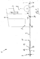
- FIGS. 1 and 2 shown in a side view truck 1, for example, designed as a pallet truck or pallet truck, has a drive part 2, which is provided with a steerable drive wheel 3, and a relatively liftable to the drive part 2 load part 4.
- the load part 4 preferably comprises two laterally spaced wheel arms 5, which are supported on a roadway F by means of load rollers 6 arranged at the tip of the respective wheel arm 5.
- the drive part 3 is supported by means of the drive wheel 3 on the roadway F.
- the drive member 3 may be supported on the roadway F with support rollers not shown in detail.
- the upper side of the wheel arms 5 form a load bearing surface LF with which a pallet (not shown) can be lifted underneath.
- a lifting device 7 for example one or more hydraulic cylinders, is provided, which is arranged between the drive part 2 and the load part 4.
- the lever assembly 11 may further serve as a guide for guiding the load part 4 in the lifting and lowering movement.
- the load part 4 may further include a battery-powered electric truck 1 a battery compartment 8 for a traction battery, which supplies an electrical drive of the drive wheel 3 and an electric drive of the lifting device 7 with electrical energy.
- the load rollers 6 are rotatably arranged in load roller carriers 12, which are arranged pivotably on the corresponding wheel arm 5.
- load roller carriers 12 which are arranged pivotably on the corresponding wheel arm 5.
- each have a pivot bearing 13 is provided for the pivotable mounting of the load roller carrier 12 to the respective wheel arm 5 .
- the linkage 10 are formed as tie rods
- the pivot bearing 13 is disposed in the vertical upper portion of the wheel arms 5 and trained as tie rods linkage 10 in the vertical direction below the pivot bearing 13 by means of a crosspoint 14 are pivotally connected to the load roller carrier 12.
- the wheel arms 5 of the truck 1 according to the invention have in the fully lowered position of the load part 4 a Radarm Abu H of less than 50mm, so that with the truck according to the invention 1 special pallets can be handled, which have a retraction height for the wheel arms 5 of 50mm.
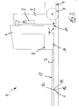
- FIGS. 3 to 9 is a structural design of the wheel arms 5 of the truck 1 of FIGS. 1 and 2 shown.
- the pivot bearing 13 of the load roller support 12 on the Radarm 5 a bearing pin 20.
- a coupling pin 21 is provided, which forms the crosspoint 14.
- the bearing pin 20 is supported in several bearing points, in the illustrated embodiment in four bearing points on the Radarm 5 and in several bearing points, in the illustrated embodiment in three bearing points , supported on the load roller carrier 12, so that the bearing pin 20 can be made with a small diameter.
- the coupling pin 21 is connected in several bearing points, in the illustrated embodiment in three bearing points with the load roller carrier 12, so that also the coupling pin 21 can be made with a small diameter.
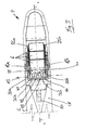
- the fork-shaped load roller carrier 12 - as in connection with the FIGS. 8 and 9 is clarified - from two lateral outer bearing levers 12a, 12b, between which rockers 25a, 25b are pivotally mounted, in which the load rollers 6, in the present embodiment, three load rollers 6, are rotatably mounted.
- the outer bearing levers 12a, 12b is for pivotal mounting of the rockers 25a, 25b respectively a bearing flange 26a, 26b formed for a bearing 27, by means of which the rockers 25a, 25b are pivotally mounted on the bearing levers 12a, 12b.
- the bearing flanges 26a, 26b for the rockers 25a, 25b are formed by a through hole in the bearing levers 12a, 12b.
- the load roller carrier 12 is provided in the region of the pivot bearing 13 and the coupling point 14 with at least one central additional web 30 which is arranged between the outer bearing levers 12a, 12b and parallel thereto.
- the Web 30 is hereby arranged and fastened by means of a connecting plate 31 between the outer bearing levers 12a, 12b.
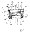
- bearing flanges 32a, 32b for supporting the bearing pin 20 and bearing flanges 33a, 33b for supporting the coupling pin 21 are formed.
- an additional bearing flange 32c for mounting the bearing pin 20 and / or an additional bearing flange 33c for mounting the coupling pin 21 is formed.
- the bearing flanges 32a, 32b, 32c for the bearing pin 20 and the bearing flanges 33a, 33b, 33c for the coupling pin 21 are each formed by a through hole in the bearing levers 12a, 12b and the web 30 of the load roller carrier 12.
- the through-holes in the load roller support 12, which form the bearing flanges 32a, 32b, 32c for the bearing bolt 20, the bearing flanges 33a, 33b, 33c for the coupling bolt 21 and the bearing flanges 26a, 26b for the rockers 25a, 25b, are arranged parallel to each other.
- the Radarm 5 has to support the bearing pin 20 - as in the Figures 3 and 6 is illustrated - on the outer sides in each case a bearing fork, which each form an outer bearing flange 35a, 35b and an inner bearing flange 36a, 36b for the bearing pin 20.
- the outer bearing levers 12a and 12b of the load roller support 12 are respectively disposed between the outer bearing flange 35a and 35b and the inner bearing flange 36a and 36b of a bearing fork of the Radarms 5.
- the bearing flanges 35a, 35b, 36a, 36b are formed to support the bearing pin 20 by a through hole, which is arranged in the corresponding bearing forks of the Radarms 5.
- the additional central web 30 of the load roller carrier 12 is in this case arranged between the two inner bearing flanges 36a, 36b of the wheel arm 5.
- the bearing pin 20 is thus alternately supported and supported in a bearing flange 35 a, 36 a, 36 b, 35 b of the Radarms 5 and a bearing flange 32 a, 32 c, 32 b of the load roller carrier 12.
- the truck 1 according to the invention is in the region of the pivot bearing 13 of the load roller carrier 12 at the top of the respective radar arm 5 continues with a
- the roller 41 is thus between the outer bearing lever 12 a of the load roller support 12 and the inner bearing flange 36 a of the Radarms 5, the roller 42 between the inner bearing flange 36 a of the Radarms 5 and the central web 30 of the load roller 12, the roller 43 between the central web 30th of the load roller support 12 and the inner bearing flange 36b of the Radarms 5 and the roller 44 between the inner bearing flange 32b of the Radarms 5 and the outer bearing lever 12b of the load roller support 12 is arranged.
- the linkage 10 is for articulated coupling with the load roller carrier 12 - as in FIG. 7 is illustrated - provided with a two bearing sections 10 a, 10 b existing bearing fork, in which a through hole 50 is formed for supporting the coupling pin 21.
- the bearing portion 10a is in this case between the outer bearing lever 12a and the central web 30 of the load roller support 12 and the bearing portion 10b between the outer bearing lever 12b and the central web 30 of the load roller support 12, so that the web 30 of the load roller support 12 between the two bearing portions 10a , 10b of the linkage 10 is arranged.
- the stop means 60 is formed by wing-like extensions 61 a, 61 b on the outer sides of the bearing levers 12 a, 12 b of the load roller carrier 12, which cooperate with stop surfaces 62 on side cheeks of the wheel arm 5.
- the stop means 60 limit the Pivoting movement of the load carrier 12 up in the fully lowered position of the wheel arms 5 and allow in conjunction with a corresponding design of the corresponding load roller carrier 12 actuated linkage 10, that in the fully lowered position, a clearance between the rollers 41, 42, 43, 44 and the linkage 10 remains, which allows rotation of the rollers 41, 42, 43, 44 on the bearing pin 20.
- the inventive bearing of the bearing pin 20 and the coupling pin 21 and the inventive design of the load roller support 12 with the additional central web 30, are arranged on the additional Lüflansche 32 c, 33 c for the bearing pin 20 and the coupling pin 21, allows the bearing pin 20 and the To reduce coupling pin 21 in diameter, so that the Radarm Abu H of the wheel arms 5 can be reduced to handle special pallets with a low retracting height can.
Landscapes
- Engineering & Computer Science (AREA)
- Transportation (AREA)
- Structural Engineering (AREA)
- Mechanical Engineering (AREA)
- Civil Engineering (AREA)
- Life Sciences & Earth Sciences (AREA)
- Geology (AREA)
- Chemical & Material Sciences (AREA)
- Combustion & Propulsion (AREA)
- Handcart (AREA)
Applications Claiming Priority (2)
| Application Number | Priority Date | Filing Date | Title |
|---|---|---|---|
| DE102012109790 | 2012-10-15 | ||
| DE102013100469.5A DE102013100469A1 (de) | 2012-10-15 | 2013-01-17 | Flurförderzeug mit in schwenkbaren Lastrollenträgern angeordneten Lastrollen |
Publications (3)
| Publication Number | Publication Date |
|---|---|
| EP2719603A1 true EP2719603A1 (fr) | 2014-04-16 |
| EP2719603B1 EP2719603B1 (fr) | 2016-07-06 |
| EP2719603B9 EP2719603B9 (fr) | 2016-09-14 |
Family
ID=49356194
Family Applications (1)
| Application Number | Title | Priority Date | Filing Date |
|---|---|---|---|
| EP13187296.2A Not-in-force EP2719603B9 (fr) | 2012-10-15 | 2013-10-04 | Chariot de manutention doté de galets de charge agencés dans des supports de galets de charge pivotants |
Country Status (3)
| Country | Link |
|---|---|
| US (1) | US10005650B2 (fr) |
| EP (1) | EP2719603B9 (fr) |
| DE (1) | DE102013100469A1 (fr) |
Cited By (1)
| Publication number | Priority date | Publication date | Assignee | Title |
|---|---|---|---|---|
| CN109204414A (zh) * | 2018-11-21 | 2019-01-15 | 成都炭素有限责任公司 | 一种炭素制品搬运车 |
Families Citing this family (10)
| Publication number | Priority date | Publication date | Assignee | Title |
|---|---|---|---|---|
| US10118439B1 (en) * | 2015-11-27 | 2018-11-06 | Shark Wheel, LLC | Wheel having a sinusoidal circumference |
| US10974919B2 (en) | 2012-11-14 | 2021-04-13 | Shark Wheel, Inc. | Device and method for aligning material sheets |
| US10899172B2 (en) | 2012-11-14 | 2021-01-26 | Shark Wheel, Inc. | Sinusoidal wheel |
| DE102014107082A1 (de) * | 2014-05-20 | 2015-11-26 | Jungheinrich Aktiengesellschaft | Flurförderzeug mit Rampenhubfunktion |
| JP6410943B2 (ja) * | 2015-08-04 | 2018-10-24 | 三菱電機株式会社 | ファンユニット取り付け構造および電子機器 |
| US9505595B1 (en) * | 2015-11-06 | 2016-11-29 | James Nelson Smith | Rapid delivery pallet jack system |
| CN106966334B (zh) * | 2017-03-10 | 2023-06-20 | 诺力智能装备股份有限公司 | 一种叉车前承重轮组结构 |
| USD898324S1 (en) * | 2018-08-30 | 2020-10-06 | Shark Wheel, Inc. | Pallet truck wheels |
| SE544748C2 (en) * | 2020-09-14 | 2022-11-01 | Toyota Mat Handling Manufacturing Sweden Ab | A support roller arrangement for a lift truck and a fork lift truck |
| DE102021121221A1 (de) | 2021-08-16 | 2023-02-16 | Jungheinrich Aktiengesellschaft | Lastrolleneinheit für ein Flurförderzeug und Flurförderzeug |
Citations (5)
| Publication number | Priority date | Publication date | Assignee | Title |
|---|---|---|---|---|
| SE352868B (fr) * | 1971-04-21 | 1973-01-15 | Bygg Och Transportekonomie Ab | |
| US5354080A (en) * | 1993-05-20 | 1994-10-11 | Jones Robert E | Industrial truck for double-faced pallets |
| DE102006035822A1 (de) * | 2006-08-01 | 2008-02-07 | Still Wagner Gmbh | Flurförderzeug mit Lastrollen und Abweisern |
| EP1690823B1 (fr) | 2005-02-15 | 2010-04-21 | OM Carrelli Elevatori S.p.A. | Chariot de manutention |
| DE102009033709A1 (de) | 2009-07-18 | 2011-01-20 | Jungheinrich Ag | Flurförderzeug mit einer Rahmenkonstruktion |
Family Cites Families (9)
| Publication number | Priority date | Publication date | Assignee | Title |
|---|---|---|---|---|
| US2178647A (en) * | 1938-03-25 | 1939-11-07 | Lyon Iron Works | Lift truck |
| US2422538A (en) * | 1943-10-12 | 1947-06-17 | Yale & Towne Mfg Co | Pallet truck |
| US2462007A (en) * | 1946-05-03 | 1949-02-15 | Irvin F Schreck | Auxiliary supporting roller arrangement for pallet trucks |
| US2550548A (en) * | 1947-08-26 | 1951-04-24 | Herbert J Framhein | Pallet truck |
| US2623756A (en) * | 1950-07-07 | 1952-12-30 | Clark Equipment Co | Pivoted load lifting mechanism |
| US3525501A (en) * | 1968-05-17 | 1970-08-25 | Eaton Yale & Towne | Pallet truck assisting means |
| DE3132703C1 (de) * | 1981-08-19 | 1983-04-14 | Jungheinrich Unternehmensverwaltung Kg, 2000 Hamburg | "Hubwagen, insbesondere Gabelhubwagen" |
| EP1190928A1 (fr) * | 2000-09-21 | 2002-03-27 | Anders Fransson | Dispositif à ressort pour le support des galets de roulement d' un élévateur à fourche |
| US8336913B1 (en) * | 2009-05-07 | 2012-12-25 | Grand Steer Inc. | Steering device for pallet jack |
-
2013
- 2013-01-17 DE DE102013100469.5A patent/DE102013100469A1/de not_active Withdrawn
- 2013-10-01 US US14/042,847 patent/US10005650B2/en active Active
- 2013-10-04 EP EP13187296.2A patent/EP2719603B9/fr not_active Not-in-force
Patent Citations (5)
| Publication number | Priority date | Publication date | Assignee | Title |
|---|---|---|---|---|
| SE352868B (fr) * | 1971-04-21 | 1973-01-15 | Bygg Och Transportekonomie Ab | |
| US5354080A (en) * | 1993-05-20 | 1994-10-11 | Jones Robert E | Industrial truck for double-faced pallets |
| EP1690823B1 (fr) | 2005-02-15 | 2010-04-21 | OM Carrelli Elevatori S.p.A. | Chariot de manutention |
| DE102006035822A1 (de) * | 2006-08-01 | 2008-02-07 | Still Wagner Gmbh | Flurförderzeug mit Lastrollen und Abweisern |
| DE102009033709A1 (de) | 2009-07-18 | 2011-01-20 | Jungheinrich Ag | Flurförderzeug mit einer Rahmenkonstruktion |
Cited By (1)
| Publication number | Priority date | Publication date | Assignee | Title |
|---|---|---|---|---|
| CN109204414A (zh) * | 2018-11-21 | 2019-01-15 | 成都炭素有限责任公司 | 一种炭素制品搬运车 |
Also Published As
| Publication number | Publication date |
|---|---|
| EP2719603B1 (fr) | 2016-07-06 |
| DE102013100469A1 (de) | 2014-04-17 |
| EP2719603B9 (fr) | 2016-09-14 |
| US10005650B2 (en) | 2018-06-26 |
| US20140175350A1 (en) | 2014-06-26 |
Similar Documents
| Publication | Publication Date | Title |
|---|---|---|
| EP2719603B9 (fr) | Chariot de manutention doté de galets de charge agencés dans des supports de galets de charge pivotants | |
| EP1808402B1 (fr) | Chariot élévateur à petite levée | |
| EP2719602B1 (fr) | Chariot de manutention doté de galets de charge agencés dans des supports de galets de charge au niveau d'un bras de roue | |
| EP2719601B1 (fr) | Chariot de manutention, en particulier chariot élévateur | |
| DE102009033709A1 (de) | Flurförderzeug mit einer Rahmenkonstruktion | |
| DE102004018910A1 (de) | Flurfolgefahrzeug | |
| EP0801013A1 (fr) | Récipient collecteur de déchets | |
| EP2020358B1 (fr) | Chariot élévateur doté de bras de charge | |
| DE2524163C3 (de) | Gabelhubwagen | |
| EP2065334A1 (fr) | Mécanisme de basculement pour un châssis de levage d'un chariot de manutention et procédé de transport pour un chariot de manutention | |
| DE102009059949A1 (de) | Flurförderzeug mit Antriebsteil und einem Paar von Radarmen | |
| DE102006014338A1 (de) | Schlepper zum Transport von fahrbaren Transportbehältern | |
| EP2019014B1 (fr) | Chariot élévateur | |
| EP3354535B1 (fr) | Chariot de manutention, en particulier chariot élévateur | |
| DE102006014336A1 (de) | Schlepper mit einer Kupplungsvorrichtung | |
| DE102018118017A1 (de) | Flurförderzeug | |
| DE102008049072A1 (de) | Flurförderzeug | |
| DE6812638U (de) | Mit einer ladeplattform versehenes kraftfahrzeug. | |
| EP1275572A2 (fr) | Flotte de chariots élévateurs et son procédé de production | |
| EP1688300B1 (fr) | Dispositif pour charger et décharger une plate-forme | |
| DE102016107538A1 (de) | Flurförderzeug mit einem Paar von in der Höhe verstellbaren Gabelarmen | |
| EP2128076B1 (fr) | Agencement de levage pour un chariot de manutention | |
| DE102021102061A1 (de) | Flurförderzeug mit einem Lastrahmen | |
| DE102007036643A1 (de) | Hubwagen | |
| DE202019104986U1 (de) | Flurförderzeug mit Gabelzinken |
Legal Events
| Date | Code | Title | Description |
|---|---|---|---|
| PUAI | Public reference made under article 153(3) epc to a published international application that has entered the european phase |
Free format text: ORIGINAL CODE: 0009012 |
|
| AK | Designated contracting states |
Kind code of ref document: A1 Designated state(s): AL AT BE BG CH CY CZ DE DK EE ES FI FR GB GR HR HU IE IS IT LI LT LU LV MC MK MT NL NO PL PT RO RS SE SI SK SM TR |
|
| AX | Request for extension of the european patent |
Extension state: BA ME |
|
| 17P | Request for examination filed |
Effective date: 20141008 |
|
| RBV | Designated contracting states (corrected) |
Designated state(s): AL AT BE BG CH CY CZ DE DK EE ES FI FR GB GR HR HU IE IS IT LI LT LU LV MC MK MT NL NO PL PT RO RS SE SI SK SM TR |
|
| 17Q | First examination report despatched |
Effective date: 20150428 |
|
| GRAP | Despatch of communication of intention to grant a patent |
Free format text: ORIGINAL CODE: EPIDOSNIGR1 |
|
| INTG | Intention to grant announced |
Effective date: 20160303 |
|
| GRAS | Grant fee paid |
Free format text: ORIGINAL CODE: EPIDOSNIGR3 |
|
| GRAA | (expected) grant |
Free format text: ORIGINAL CODE: 0009210 |
|
| AK | Designated contracting states |
Kind code of ref document: B1 Designated state(s): AL AT BE BG CH CY CZ DE DK EE ES FI FR GB GR HR HU IE IS IT LI LT LU LV MC MK MT NL NO PL PT RO RS SE SI SK SM TR |
|
| REG | Reference to a national code |
Ref country code: GB Ref legal event code: FG4D Free format text: NOT ENGLISH |
|
| REG | Reference to a national code |
Ref country code: AT Ref legal event code: REF Ref document number: 810472 Country of ref document: AT Kind code of ref document: T Effective date: 20160715 Ref country code: CH Ref legal event code: EP |
|
| REG | Reference to a national code |
Ref country code: IE Ref legal event code: FG4D Free format text: LANGUAGE OF EP DOCUMENT: GERMAN |
|
| REG | Reference to a national code |
Ref country code: DE Ref legal event code: R096 Ref document number: 502013003591 Country of ref document: DE |
|
| REG | Reference to a national code |
Ref country code: SE Ref legal event code: TRGR |
|
| REG | Reference to a national code |
Ref country code: FR Ref legal event code: PLFP Year of fee payment: 4 |
|
| REG | Reference to a national code |
Ref country code: NL Ref legal event code: MP Effective date: 20160706 |
|
| REG | Reference to a national code |
Ref country code: LT Ref legal event code: MG4D |
|
| REG | Reference to a national code |
Ref country code: DE Ref legal event code: R082 Ref document number: 502013003591 Country of ref document: DE Representative=s name: PATENTSHIP PATENTANWALTSGESELLSCHAFT MBH, DE |
|
| PG25 | Lapsed in a contracting state [announced via postgrant information from national office to epo] |
Ref country code: LT Free format text: LAPSE BECAUSE OF FAILURE TO SUBMIT A TRANSLATION OF THE DESCRIPTION OR TO PAY THE FEE WITHIN THE PRESCRIBED TIME-LIMIT Effective date: 20160706 Ref country code: HR Free format text: LAPSE BECAUSE OF FAILURE TO SUBMIT A TRANSLATION OF THE DESCRIPTION OR TO PAY THE FEE WITHIN THE PRESCRIBED TIME-LIMIT Effective date: 20160706 Ref country code: IS Free format text: LAPSE BECAUSE OF FAILURE TO SUBMIT A TRANSLATION OF THE DESCRIPTION OR TO PAY THE FEE WITHIN THE PRESCRIBED TIME-LIMIT Effective date: 20161106 Ref country code: NL Free format text: LAPSE BECAUSE OF FAILURE TO SUBMIT A TRANSLATION OF THE DESCRIPTION OR TO PAY THE FEE WITHIN THE PRESCRIBED TIME-LIMIT Effective date: 20160706 Ref country code: NO Free format text: LAPSE BECAUSE OF FAILURE TO SUBMIT A TRANSLATION OF THE DESCRIPTION OR TO PAY THE FEE WITHIN THE PRESCRIBED TIME-LIMIT Effective date: 20161006 Ref country code: RS Free format text: LAPSE BECAUSE OF FAILURE TO SUBMIT A TRANSLATION OF THE DESCRIPTION OR TO PAY THE FEE WITHIN THE PRESCRIBED TIME-LIMIT Effective date: 20160706 Ref country code: IT Free format text: LAPSE BECAUSE OF FAILURE TO SUBMIT A TRANSLATION OF THE DESCRIPTION OR TO PAY THE FEE WITHIN THE PRESCRIBED TIME-LIMIT Effective date: 20160706 Ref country code: FI Free format text: LAPSE BECAUSE OF FAILURE TO SUBMIT A TRANSLATION OF THE DESCRIPTION OR TO PAY THE FEE WITHIN THE PRESCRIBED TIME-LIMIT Effective date: 20160706 |
|
| REG | Reference to a national code |
Ref country code: DE Ref legal event code: R082 Ref document number: 502013003591 Country of ref document: DE Representative=s name: PATENTSHIP PATENTANWALTSGESELLSCHAFT MBH, DE |
|
| PG25 | Lapsed in a contracting state [announced via postgrant information from national office to epo] |
Ref country code: BE Free format text: LAPSE BECAUSE OF NON-PAYMENT OF DUE FEES Effective date: 20161031 Ref country code: PL Free format text: LAPSE BECAUSE OF FAILURE TO SUBMIT A TRANSLATION OF THE DESCRIPTION OR TO PAY THE FEE WITHIN THE PRESCRIBED TIME-LIMIT Effective date: 20160706 Ref country code: LV Free format text: LAPSE BECAUSE OF FAILURE TO SUBMIT A TRANSLATION OF THE DESCRIPTION OR TO PAY THE FEE WITHIN THE PRESCRIBED TIME-LIMIT Effective date: 20160706 Ref country code: ES Free format text: LAPSE BECAUSE OF FAILURE TO SUBMIT A TRANSLATION OF THE DESCRIPTION OR TO PAY THE FEE WITHIN THE PRESCRIBED TIME-LIMIT Effective date: 20160706 Ref country code: GR Free format text: LAPSE BECAUSE OF FAILURE TO SUBMIT A TRANSLATION OF THE DESCRIPTION OR TO PAY THE FEE WITHIN THE PRESCRIBED TIME-LIMIT Effective date: 20161007 Ref country code: PT Free format text: LAPSE BECAUSE OF FAILURE TO SUBMIT A TRANSLATION OF THE DESCRIPTION OR TO PAY THE FEE WITHIN THE PRESCRIBED TIME-LIMIT Effective date: 20161107 |
|
| REG | Reference to a national code |
Ref country code: DE Ref legal event code: R097 Ref document number: 502013003591 Country of ref document: DE |
|
| PG25 | Lapsed in a contracting state [announced via postgrant information from national office to epo] |
Ref country code: RO Free format text: LAPSE BECAUSE OF FAILURE TO SUBMIT A TRANSLATION OF THE DESCRIPTION OR TO PAY THE FEE WITHIN THE PRESCRIBED TIME-LIMIT Effective date: 20160706 Ref country code: EE Free format text: LAPSE BECAUSE OF FAILURE TO SUBMIT A TRANSLATION OF THE DESCRIPTION OR TO PAY THE FEE WITHIN THE PRESCRIBED TIME-LIMIT Effective date: 20160706 |
|
| PLBE | No opposition filed within time limit |
Free format text: ORIGINAL CODE: 0009261 |
|
| STAA | Information on the status of an ep patent application or granted ep patent |
Free format text: STATUS: NO OPPOSITION FILED WITHIN TIME LIMIT |
|
| PG25 | Lapsed in a contracting state [announced via postgrant information from national office to epo] |
Ref country code: DK Free format text: LAPSE BECAUSE OF FAILURE TO SUBMIT A TRANSLATION OF THE DESCRIPTION OR TO PAY THE FEE WITHIN THE PRESCRIBED TIME-LIMIT Effective date: 20160706 Ref country code: SK Free format text: LAPSE BECAUSE OF FAILURE TO SUBMIT A TRANSLATION OF THE DESCRIPTION OR TO PAY THE FEE WITHIN THE PRESCRIBED TIME-LIMIT Effective date: 20160706 Ref country code: SM Free format text: LAPSE BECAUSE OF FAILURE TO SUBMIT A TRANSLATION OF THE DESCRIPTION OR TO PAY THE FEE WITHIN THE PRESCRIBED TIME-LIMIT Effective date: 20160706 Ref country code: BG Free format text: LAPSE BECAUSE OF FAILURE TO SUBMIT A TRANSLATION OF THE DESCRIPTION OR TO PAY THE FEE WITHIN THE PRESCRIBED TIME-LIMIT Effective date: 20161006 Ref country code: CZ Free format text: LAPSE BECAUSE OF FAILURE TO SUBMIT A TRANSLATION OF THE DESCRIPTION OR TO PAY THE FEE WITHIN THE PRESCRIBED TIME-LIMIT Effective date: 20160706 |
|
| REG | Reference to a national code |
Ref country code: CH Ref legal event code: PL |
|
| 26N | No opposition filed |
Effective date: 20170407 |
|
| REG | Reference to a national code |
Ref country code: IE Ref legal event code: MM4A |
|
| PG25 | Lapsed in a contracting state [announced via postgrant information from national office to epo] |
Ref country code: LI Free format text: LAPSE BECAUSE OF NON-PAYMENT OF DUE FEES Effective date: 20161031 Ref country code: CH Free format text: LAPSE BECAUSE OF NON-PAYMENT OF DUE FEES Effective date: 20161031 |
|
| PG25 | Lapsed in a contracting state [announced via postgrant information from national office to epo] |
Ref country code: LU Free format text: LAPSE BECAUSE OF NON-PAYMENT OF DUE FEES Effective date: 20161004 Ref country code: SI Free format text: LAPSE BECAUSE OF FAILURE TO SUBMIT A TRANSLATION OF THE DESCRIPTION OR TO PAY THE FEE WITHIN THE PRESCRIBED TIME-LIMIT Effective date: 20160706 |
|
| REG | Reference to a national code |
Ref country code: FR Ref legal event code: PLFP Year of fee payment: 5 |
|
| PG25 | Lapsed in a contracting state [announced via postgrant information from national office to epo] |
Ref country code: IE Free format text: LAPSE BECAUSE OF NON-PAYMENT OF DUE FEES Effective date: 20161004 |
|
| REG | Reference to a national code |
Ref country code: BE Ref legal event code: MM Effective date: 20161031 |
|
| PG25 | Lapsed in a contracting state [announced via postgrant information from national office to epo] |
Ref country code: HU Free format text: LAPSE BECAUSE OF FAILURE TO SUBMIT A TRANSLATION OF THE DESCRIPTION OR TO PAY THE FEE WITHIN THE PRESCRIBED TIME-LIMIT; INVALID AB INITIO Effective date: 20131004 Ref country code: CY Free format text: LAPSE BECAUSE OF FAILURE TO SUBMIT A TRANSLATION OF THE DESCRIPTION OR TO PAY THE FEE WITHIN THE PRESCRIBED TIME-LIMIT Effective date: 20160706 |
|
| GBPC | Gb: european patent ceased through non-payment of renewal fee |
Effective date: 20171004 |
|
| PG25 | Lapsed in a contracting state [announced via postgrant information from national office to epo] |
Ref country code: MK Free format text: LAPSE BECAUSE OF FAILURE TO SUBMIT A TRANSLATION OF THE DESCRIPTION OR TO PAY THE FEE WITHIN THE PRESCRIBED TIME-LIMIT Effective date: 20160706 Ref country code: MT Free format text: LAPSE BECAUSE OF FAILURE TO SUBMIT A TRANSLATION OF THE DESCRIPTION OR TO PAY THE FEE WITHIN THE PRESCRIBED TIME-LIMIT Effective date: 20160706 Ref country code: MC Free format text: LAPSE BECAUSE OF FAILURE TO SUBMIT A TRANSLATION OF THE DESCRIPTION OR TO PAY THE FEE WITHIN THE PRESCRIBED TIME-LIMIT Effective date: 20160706 |
|
| PG25 | Lapsed in a contracting state [announced via postgrant information from national office to epo] |
Ref country code: GB Free format text: LAPSE BECAUSE OF NON-PAYMENT OF DUE FEES Effective date: 20171004 |
|
| REG | Reference to a national code |
Ref country code: FR Ref legal event code: PLFP Year of fee payment: 6 |
|
| PG25 | Lapsed in a contracting state [announced via postgrant information from national office to epo] |
Ref country code: TR Free format text: LAPSE BECAUSE OF FAILURE TO SUBMIT A TRANSLATION OF THE DESCRIPTION OR TO PAY THE FEE WITHIN THE PRESCRIBED TIME-LIMIT Effective date: 20160706 Ref country code: AL Free format text: LAPSE BECAUSE OF FAILURE TO SUBMIT A TRANSLATION OF THE DESCRIPTION OR TO PAY THE FEE WITHIN THE PRESCRIBED TIME-LIMIT Effective date: 20160706 |
|
| PGFP | Annual fee paid to national office [announced via postgrant information from national office to epo] |
Ref country code: SE Payment date: 20181025 Year of fee payment: 6 Ref country code: DE Payment date: 20181024 Year of fee payment: 6 |
|
| PGFP | Annual fee paid to national office [announced via postgrant information from national office to epo] |
Ref country code: FR Payment date: 20181023 Year of fee payment: 6 |
|
| REG | Reference to a national code |
Ref country code: AT Ref legal event code: MM01 Ref document number: 810472 Country of ref document: AT Kind code of ref document: T Effective date: 20181004 |
|
| PG25 | Lapsed in a contracting state [announced via postgrant information from national office to epo] |
Ref country code: AT Free format text: LAPSE BECAUSE OF NON-PAYMENT OF DUE FEES Effective date: 20181004 |
|
| REG | Reference to a national code |
Ref country code: DE Ref legal event code: R119 Ref document number: 502013003591 Country of ref document: DE |
|
| PG25 | Lapsed in a contracting state [announced via postgrant information from national office to epo] |
Ref country code: DE Free format text: LAPSE BECAUSE OF NON-PAYMENT OF DUE FEES Effective date: 20200501 |
|
| PG25 | Lapsed in a contracting state [announced via postgrant information from national office to epo] |
Ref country code: SE Free format text: LAPSE BECAUSE OF NON-PAYMENT OF DUE FEES Effective date: 20191005 |
|
| PG25 | Lapsed in a contracting state [announced via postgrant information from national office to epo] |
Ref country code: FR Free format text: LAPSE BECAUSE OF NON-PAYMENT OF DUE FEES Effective date: 20191031 |