EP2719601B1 - Chariot de manutention, en particulier chariot élévateur - Google Patents
Chariot de manutention, en particulier chariot élévateur Download PDFInfo
- Publication number
- EP2719601B1 EP2719601B1 EP13187294.7A EP13187294A EP2719601B1 EP 2719601 B1 EP2719601 B1 EP 2719601B1 EP 13187294 A EP13187294 A EP 13187294A EP 2719601 B1 EP2719601 B1 EP 2719601B1
- Authority
- EP
- European Patent Office
- Prior art keywords
- lever
- load part
- industrial truck
- truck according
- point
- Prior art date
- Legal status (The legal status is an assumption and is not a legal conclusion. Google has not performed a legal analysis and makes no representation as to the accuracy of the status listed.)
- Active
Links
- 230000008878 coupling Effects 0.000 claims description 32
- 238000010168 coupling process Methods 0.000 claims description 32
- 238000005859 coupling reaction Methods 0.000 claims description 32
- 230000002349 favourable effect Effects 0.000 description 2
- 239000011111 cardboard Substances 0.000 description 1
- 238000006880 cross-coupling reaction Methods 0.000 description 1
- 238000004519 manufacturing process Methods 0.000 description 1
- 239000011087 paperboard Substances 0.000 description 1
Images


Classifications
-
- B—PERFORMING OPERATIONS; TRANSPORTING
- B62—LAND VEHICLES FOR TRAVELLING OTHERWISE THAN ON RAILS
- B62B—HAND-PROPELLED VEHICLES, e.g. HAND CARTS OR PERAMBULATORS; SLEDGES
- B62B3/00—Hand carts having more than one axis carrying transport wheels; Steering devices therefor; Equipment therefor
- B62B3/04—Hand carts having more than one axis carrying transport wheels; Steering devices therefor; Equipment therefor involving means for grappling or securing in place objects to be carried; Loading or unloading equipment
- B62B3/06—Hand carts having more than one axis carrying transport wheels; Steering devices therefor; Equipment therefor involving means for grappling or securing in place objects to be carried; Loading or unloading equipment for simply clearing the load from the ground
- B62B3/0625—Hand carts having more than one axis carrying transport wheels; Steering devices therefor; Equipment therefor involving means for grappling or securing in place objects to be carried; Loading or unloading equipment for simply clearing the load from the ground using rigid mechanical lifting mechanisms, e.g. levers, cams or gears
- B62B3/0631—Hand carts having more than one axis carrying transport wheels; Steering devices therefor; Equipment therefor involving means for grappling or securing in place objects to be carried; Loading or unloading equipment for simply clearing the load from the ground using rigid mechanical lifting mechanisms, e.g. levers, cams or gears with a parallelogram linkage
-
- B—PERFORMING OPERATIONS; TRANSPORTING
- B66—HOISTING; LIFTING; HAULING
- B66F—HOISTING, LIFTING, HAULING OR PUSHING, NOT OTHERWISE PROVIDED FOR, e.g. DEVICES WHICH APPLY A LIFTING OR PUSHING FORCE DIRECTLY TO THE SURFACE OF A LOAD
- B66F9/00—Devices for lifting or lowering bulky or heavy goods for loading or unloading purposes
- B66F9/06—Devices for lifting or lowering bulky or heavy goods for loading or unloading purposes movable, with their loads, on wheels or the like, e.g. fork-lift trucks
- B66F9/075—Constructional features or details
- B66F9/12—Platforms; Forks; Other load supporting or gripping members
-
- B—PERFORMING OPERATIONS; TRANSPORTING
- B66—HOISTING; LIFTING; HAULING
- B66F—HOISTING, LIFTING, HAULING OR PUSHING, NOT OTHERWISE PROVIDED FOR, e.g. DEVICES WHICH APPLY A LIFTING OR PUSHING FORCE DIRECTLY TO THE SURFACE OF A LOAD
- B66F9/00—Devices for lifting or lowering bulky or heavy goods for loading or unloading purposes
- B66F9/06—Devices for lifting or lowering bulky or heavy goods for loading or unloading purposes movable, with their loads, on wheels or the like, e.g. fork-lift trucks
- B66F9/065—Devices for lifting or lowering bulky or heavy goods for loading or unloading purposes movable, with their loads, on wheels or the like, e.g. fork-lift trucks non-masted
Definitions
- the invention relates to an industrial truck, in particular lift truck, with a drive part and a liftable relative to the drive part load part, wherein the load part has at least one wheel arm, which is provided with at least one load roller, wherein for raising the Radarms standing with the load roller in operative connection linkage and a linkage actuated lever assembly is provided, wherein the lever assembly comprises a first lever which is pivotally mounted with a first bearing point on the drive part and is pivotally mounted with a second bearing point on the load part, and a second lever having a bearing point on the Load part is pivotally mounted and coupled with a crosspoint with the linkage.
- Known forklifts with wheel arms are used to drive with the radar arms under a pallet and lift the pallet. To raise the pallet, the wheel arms are raised.
- the load part is raised relative to the drive part, wherein pivotably arranged on the Radarmen Radarmhebel in which the load rollers are mounted, are operated via the lever assembly and the linkage to raise the wheel arms.
- Such a lifting movement is referred to as Niederhub at low pallet truck or picking or stackers with an additional mast as Initialhub.
- a generic pallet truck is from the DE 10 2004 057 777 A1 known.
- the lever assembly for actuating the associated with the Radarmhebeln linkage consists of two Parallelogrammhebeln.
- An upper, first parallelogram lever is pivotally mounted with a first bearing point on the drive part and pivotally mounted with a second bearing point on the load part.
- a lower, second Parallelogrammhebel is pivotally mounted with a bearing point on the load part and coupled with a crosspoint with the linkage.
- the lower, second Parallelogrammhebel is still pivotally mounted on a further bearing point on the drive part.
- Pallet truck with load rollers on the Radarmen which are actuated by means of a linkage and a lever assembly are, for example, from EP 1 690 823 B1 or the DE 10 2009 033 709 A1 known.
- the lever arrangement consists of a swivel mounted on the load part lever, which is further stored or supported on the drive part and coupled to the linkage.
- Known lever arrangement lead in a lifting or pivoting movement to a pivoting of the trained as a pull rod or push rod linkage, in which the linkage depending on the constructive embodiment of the outlines of the radar arms dive down.
- Known lifting trucks are designed for the handling of standardized Europlatten, which have an entry height for the wheel arms of 100mm and this in the fully lowered position a Radarm Abu the arms have in the range of about 85mm.
- the present invention has for its object to provide an industrial truck of the type mentioned, which is improved in terms of the kinematics of the linkage and a space-saving design of the wheel arms with a low Radarm almost in the lowered position of the load part for handling special pallets with a small Entry height allows.
- the lever assembly comprises an intermediate lever which is connected to a crosspoint of the first lever and a further crosspoint of the second lever.
- the linkage is actuated via the second lever, which is actuated when lifting the load part of the first lever by means of the intermediate lever and thus pivoted.
- the lever assembly according to the invention in this case allows the lifting and lowering of the wheel arms a horizontal movement of the linkage without disturbing pivoting, so that the height of the wheel arms can be reduced and prevents the abutment of the linkage on the road or the recorded on the Radarmen pallet when raising and lowering can be.
- the radar height in the fully lowered position of the load part can thus be reduced in a simple manner such that special plates can be handled with a reduced entry height for the wheel arms compared to europallets.
- the linkage is designed as a tie rod.
- Link rods designed as a linkage allow a space-saving coupling with the load rollers supporting pivoting Radarmhebeln in the Radarmen.
- the second bearing point of the first lever and the bearing point of the second lever are spaced apart on the load part in the vertical direction, wherein the bearing point of the second lever is arranged above the second bearing point of the first lever.
- the first lever is designed as a two-armed lever, wherein the first bearing point is formed on a first lever arm and the coupling point for the intermediate lever is formed on a second lever arm.
- Such a two-armed lever can be mounted in a simple manner between the two lever arms on the load part to pivot over the intermediate lever to actuate the second lever.
- the second lever is designed as an angle lever, being formed on a first lever arm of the crosspoint for the linkage and on a second lever arm of the crosspoint for the intermediate lever.
- Such an angle lever can be mounted pivotably on the load part in a simple manner and allows a horizontal movement of the linkage via the first lever arm.
- the second lever is arranged on the load part such that the bearing point on the load part and the coupling point for the intermediate lever are arranged in the vertical direction above the coupling point for the linkage.
- the second lever is arranged on the load part such that the further coupling point of the second lever for the intermediate lever is arranged in the vertical direction above the coupling point of the first lever for the intermediate lever.
- the intermediate lever is immersed in the first lever in the region of the coupling point at fully lowered load part.
- the intermediate lever has a U-shaped cross section with a cutout, in which the second lever is immersed over the entire stroke range of the load part.
- This embodiment of the two levers and the intermediate lever results in the vertical direction an interleaved arrangement of the lever assembly with low height in the vertical direction, which allows a small overall height of the wheel arms at fully lowered load part.
- the bearing point of the second lever is adjustable to the load part by means of an adjusting means.
- the load rollers on the two Radarmen and thus the arms should be set at the same height to achieve a uniform lifting and lowering of the two arms and to compensate for component tolerances.
- the bearing point is formed on a bearing block, which is adjustable in the horizontal longitudinal direction of the load part by means of the adjusting means.
- the bearing block is guided adjustably in oblong holes on a bottom plate of the load part. This results in a lower manufacturing cost for the adjustment of the bearing block.
- the adjusting means is formed by an adjusting screw, which is in operative connection with the bearing block and the load part.
- the bearing block With an adjusting screw, the bearing block can be sensitively and accurately adjusted to adjust the wheel arms.
- the wheel arms in the fully lowered position of the load part on a Radarm Abu below 50mm.
- the space-saving lever assembly according to the invention allows the kinematics of trained as tie rods boom compared to known trucks a significant reduction of Radarm Abu lowered radar arms, so that with the truck according to the invention special pallets, for example made of paper or cardboard pallets, with a reduced compared to Euro pallets entry height with the radar can be driven under and raised.
- the invention further relates to a system consisting of a truck with a Radarm Abu the arms in the fully lowered position of the load part of at most 50mm and a special range, which has a retracting height for the wheel arms of the truck of 50mm.
- a truck according to the invention which is provided due to the lever assembly according to the invention with a low radar height of the wheel arms in the lowered position, special pallets can be handled safely and easily with a low retracting height.
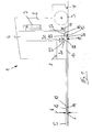
- FIGS. 1 to 3 shown in a side view truck 1, for example, designed as a pallet truck or pallet truck, has a drive part 2, which is provided with a steerable drive wheel 3, and a relatively liftable to the drive part 2 load part 4.
- the load part 4 preferably comprises two laterally spaced wheel arms 5, which are supported by means of load rollers 6 at the top of the respective wheel arm 5 on the roadway F.
- the drive part 2 is supported by means of the drive wheel 3 on the roadway F. To increase the stability of the drive member 2 may be supported with support rollers not shown in detail on the roadway F.
- a lifting device 7 for example one or more hydraulic cylinders, is provided which is arranged between the drive part 2 and the load part 4.
- a lifting device 7 for example one or more hydraulic cylinders, is provided which is arranged between the drive part 2 and the load part 4.
- the load rollers 6 In order to transmit the lifting movement of the load part 4 on the load rollers 6 at the ends of the wheel arms 5, for each wheel 5 is a standing with the load rollers 6 in operative connection linkage 10 and the linkage 10 actuated lever assembly 11 is provided.
- the lever assembly 11 also serves as a guide for guiding the load part 4 in the lifting and lowering movement.
- the load part 4 may further include a battery-powered electric truck 1 a battery compartment 8 for a traction battery, which supplies an electrical drive of the drive wheel 3 and an electric drive of the lifting device 7 with electrical energy.
- the load rollers 6 are rotatably arranged in Radarmhebeln 12, which are arranged pivotably on the Radarmen 5.
- pivot bearing 13 are provided for pivotally mounting the Radarmhebel 12 in the Radarmen 5.
- the linkage 10 are formed as tie rods
- the pivot bearings 13 are arranged in the upper region of the wheel arms 5 and formed as tie rods linkage 10 in the vertical direction below the pivot bearing 13 by means of coupling points 14 are pivotally connected to the Radarmhebeln 12.
- the lever assembly 11 according to the invention for actuating the linkage 10 comprises a first lever 15 which is pivotally mounted with a first bearing point 16 on the drive part 2 and is pivotally mounted with a second bearing point 17 on the load part 3, and a second lever 20 which a bearing point 21 is pivotally mounted on the load part 4 and is coupled to a coupling point 22 with the linkage 10.
- the lever assembly 11 according to the invention further comprises an intermediate lever 25 which is connected to a coupling point 26 of the first lever 15 and a further coupling point 27 of the second lever 20.
- the first lever 15 is in this case designed as a two-armed lever, wherein in the central region of the second bearing point 17 is formed for articulated mounting of the lever 15 on the load part 4 and on a extending to the drive part 2 first lever arm of the first bearing point 16 for articulated attachment of Lever 15 is formed on the drive part 2.
- the first lever 15 is extended beyond the bearing point 17 in the direction of the load part 4 and provided with a crank arm to the first lever arm slightly upwardly bent second lever arm, on which the cross-coupling point 26 is formed for articulated articulation of the intermediate lever 25.
- the second lever 20 is formed as an angle lever which is pivotally mounted in the central region by means of the bearing point 21 on the load part 4.
- the coupling point 22 is designed for the articulated articulation of the linkage 10 and on a second lever arm which extends in the direction of the drive part 2, the coupling point 27 for articulated articulation of the intermediate lever 25.
- the second lever arm of the second lever 20 designed as an angle lever is bent down vertically with respect to the first lever arm.
- the second bearing point 17 of the first lever 15 and the bearing point 21 of the second lever 20 are arranged at a distance from the load part 4 in the vertical direction.
- the bearing point 21 of the second lever 20 is in this case arranged above the second bearing point 17 of the first lever 15.
- the second lever 20 is arranged on the load part 4 such that the bearing point 21 on the load part 4 and the coupling point 27 for the intermediate lever 25 are arranged in the vertical direction above the coupling point 22 for the linkage 10.
- the second lever 20 is arranged on the load part 4 such that the coupling point 27 is arranged for the intermediate lever 25 of the second lever 20 in the vertical direction above the coupling point 26 for the intermediate lever 25 of the first lever 15.
- an adjusting means 30 is provided, with which the bearing point 21 of the second lever 20 can be adjusted in the horizontal longitudinal direction of the load part 4.
- lever assembly 11 pivoted when lifting the load part 4 - as in the FIGS. 1 to 3 is clarified - the articulated at the bearing point 16 on the drive part 2 first lever 15 in a clockwise direction about the second bearing point 17 on the load part 4, wherein by means of the intermediate lever 25 of the second lever 20 is pivoted counterclockwise about the bearing point 21 on the load part 4.
- the lever assembly 11 according to the invention in this case a pure horizontal movement of the trained as a pull rod linkage 10 is achieved in which the trained as a pull rod linkage 10 remains within the height extent of the wheel arms 5.
- the inventive lever assembly 11 with the achievable horizontal movement of the trained as tie rods linkage 10 makes it possible to reduce the wheel arms 5 in such a height that the wheel arms 5 in the fully lowered position of the load part 4 have a Radarm Abu H of less than 50mm, so that with the truck according to the invention 1 special pallets can be handled, which have a retraction height for the wheel arms 5 of 50mm.
- FIGS. 4 to 6 is a structural design of the truck 1 of FIGS. 1 to 3 shown.
- FIGS. 4 to 6 show the state with fully raised load part. 4
- the bearing point 16 of the first lever 15 on the drive part 2 is formed by a bearing eye, in which the first lever 15 is mounted by means of a bearing pin.
- the first lever 15 is formed by two vehicle transverse direction spaced side plates 15a, 15b and a stiffening plate 15c.
- the bearing point 17 of the first lever 15 on the load part 4 is formed by two side plates 17a, 17b spaced apart in the vehicle transverse direction, between which the first lever 15 is pivotally mounted by means of a bearing pin.
- the side plates 17a, 17b are arranged here on the underside of a bottom plate 50 of the battery compartment 8.
- the intermediate lever 25 is formed as a curved, in cross-section U-shaped tab which is pivotally mounted by means of bearing bolts on the first lever 15 and the second lever 20, which form the coupling points 26, 27.
- the intermediate lever 25 is disposed between the side plates 15a, 15b of the first lever 15.
- the lug-shaped intermediate lever 25 is formed by two side plates spaced in the vehicle transverse direction and a tubular connecting piece connecting the side plates.
- the tubular connecting piece is arranged between the side plates 15a, 15b of the first lever 15 and receives the bearing pin, which forms the coupling point 26 for the articulated articulation of the intermediate lever 25 on the first lever 15 and for this purpose received in the side plates 15a, 15b of the first lever 15 is.
- the second lever 20 is formed as an angle lever-like tab, wherein the second lever arm, which extends in the direction of the drive part 2 and on which the coupling pin formed by the bearing pin 27 is formed centrally between the two side plates of the intermediate lever 25 and the side plates the intermediate lever 25 formed U-shaped cutout is arranged.
- the coupling point 27 forming bearing pin is in this case added to the two side plates of the intermediate lever 25 and the lever 20.
- the levers 15, 20 and the intermediate lever 25 are arranged in the vertical direction nested over the entire stroke range, so that a low overall height of the wheel arms 5 is achieved at fully lowered load part 4.
- the intermediate lever 25 with the crosspoint 27 is immersed in the maximum extent in the region of the stiffening plate 15c in the first lever 15.
- the second lever 20 is immersed over the entire stroke range of the load part 4 in the cutout formed by the two side plates of the intermediate lever 25.
- the bearing point 21 of the second lever 20 on the load part 4 is formed on a bearing block 35, on which the second lever 20 is pivotally mounted by means of a bearing pin.
- the bearing block 35 is secured to the underside of the bottom plate 50 of the battery compartment by means of a plurality of screw 36, which are arranged in slots 37 of the bottom plate 50.
- the elongated holes 37 extend in the vehicle longitudinal direction, so that the bearing block 35 and thus the bearing point 21 of the second lever 20 in the vehicle longitudinal direction is adjustable.
- adjustment means 30 is provided, which communicates with the bearing block 35 and a fixed to the bottom plate 50 abutment 39 in connection.
- Trained as tie rods linkage 10 are provided for articulated connection with the second lever 20 with a bearing fork 40 which are pivotally mounted by means of a bearing pin at the crosspoint 22 of the second lever 20.
- the wheel arms 5 each have two laterally spaced side members 5a, 5b, between which a receiving channel 45 is formed for the rod 10.
Landscapes
- Engineering & Computer Science (AREA)
- Transportation (AREA)
- Structural Engineering (AREA)
- Mechanical Engineering (AREA)
- Civil Engineering (AREA)
- Life Sciences & Earth Sciences (AREA)
- Geology (AREA)
- Chemical & Material Sciences (AREA)
- Combustion & Propulsion (AREA)
- Handcart (AREA)
Claims (15)
- Chariot de manutention (1), en particulier chariot élévateur, comprenant une partie d'entraînement (2) et une partie de charge (4) pouvant être soulevée par rapport à la partie d'entraînement (2), la partie de charge (4) présentant au moins un bras de roue (5) qui est muni d'au moins un rouleau de charge (6), une tringlerie (10) en liaison fonctionnelle avec le rouleau de charge (6) et un agencement de levier (11) actionnant la tringlerie (10) étant prévus pour le soulèvement du bras de roue (5), l'agencement de levier (11) présentant un premier levier (15) qui est supporté de manière pivotante par un premier point de palier (16) au niveau de la partie d'entraînement (2) et par un deuxième point de palier (17) au niveau de la partie de charge (4), et un deuxième levier (20) qui est supporté de manière pivotante par un point de palier (21) sur la partie de charge (4) et qui est accouplé à la tringlerie (10) par un point d'accouplement (22), caractérisé en ce que l'agencement de levier (11) comprend un levier intermédiaire (25) qui est connecté à un point d'accouplement (26) du premier levier (15) et à un point d'accouplement supplémentaire (27) du deuxième levier (20).
- Chariot de manutention selon la revendication 1, caractérisé en ce que la tringlerie (10) est réalisée sous forme de barre de traction.
- Chariot de manutention selon la revendication 1 ou 2, caractérisé en ce que le deuxième point de palier (17) du premier levier (15) et le point de palier (21) du deuxième levier (20) sont disposés de manière espacée dans la direction verticale sur la partie de charge (4), le point de palier (21) du deuxième levier (20) étant disposé au-dessus du deuxième point de palier (17) du premier levier (15).
- Chariot de manutention selon l'une quelconque des revendications 1 à 3, caractérisé en ce que le premier levier (15) est réalisé sous forme de levier à deux bras, le premier point de palier (16) étant réalisé au niveau d'un premier bras de levier et le point d'accouplement (26) pour le levier intermédiaire (25) étant réalisé au niveau d'un deuxième bras de levier.
- Chariot de manutention selon l'une quelconque des revendications 1 à 4, caractérisé en ce que le deuxième levier (20) est réalisé sous forme de levier coudé, le point d'accouplement (22) pour la tringlerie (10) étant réalisé au niveau d'un premier bras de levier et le point d'accouplement (27) pour le levier intermédiaire (25) étant réalisé au niveau d'un deuxième bras de levier.
- Chariot de manutention selon l'une quelconque des revendications 1 à 5, caractérisé en ce que le deuxième levier (20) est disposé au niveau de la partie de charge (4) de telle sorte que le point de palier (21) soit disposé au niveau de la partie de charge (4) et que le point d'accouplement (27) pour le levier intermédiaire (25) soit disposé dans la direction verticale au-dessus du point d'accouplement (22) pour la tringlerie (10).
- Chariot de manutention selon l'une quelconque des revendications 1 à 6, caractérisé en ce que le deuxième levier (20) est disposé au niveau de la partie de charge (4) de telle sorte que le point d'accouplement supplémentaire (27) du deuxième levier (20) pour le levier intermédiaire (25) soit disposé dans la direction verticale au-dessus du point d'accouplement (26) du premier levier (15) pour le levier intermédiaire (25).
- Chariot de manutention selon l'une quelconque des revendications 1 à 7, caractérisé en ce que lorsque la partie de charge (4) est complètement abaissée, le levier intermédiaire (25) est plongé dans la région du point d'accouplement (27) dans le premier levier (15).
- Chariot de manutention selon l'une quelconque des revendications 1 à 8, caractérisé en ce que le levier intermédiaire (25) présente une section transversale en forme de U avec un évidement dans lequel le deuxième levier (20) est plongé sur toute la plage de levage de la partie de charge (4).
- Chariot de manutention selon l'une quelconque des revendications 1 à 9, caractérisé en ce que le point de palier (21) du deuxième levier (20) au niveau de la partie de charge (4) peut être ajusté au moyen d'un moyen d'ajustement (30).
- Chariot de manutention selon la revendication 10, caractérisé en ce que le point de palier (21) est réalisé au niveau d'un coussinet (35) qui peut être réglé dans la direction longitudinale horizontale de la partie de charge (4) au moyen du moyen d'ajustement (30).
- Chariot de manutention selon la revendication 10 ou 11, caractérisé en ce que le coussinet (35) est guidé de manière réglable dans des trous oblongs (37) au niveau d'une plaque de fond (50) de la partie de charge (4).
- Chariot de manutention selon l'une quelconque des revendications 10 à 12, caractérisé en ce que le moyen d'ajustement (30) est formé par une vis d'ajustement (38) qui est en liaison fonctionnelle avec le coussinet (35) et la partie de charge (4).
- Chariot de manutention selon l'une quelconque des revendications 1 à 13, caractérisé en ce que les bras de roue (5), dans la position complètement abaissée de la partie de charge (4), présentent une hauteur de bras de roue (H) inférieure à 50 mm.
- Système constitué d'un chariot de manutention selon l'une quelconque des revendications précédentes, comprenant une hauteur de bras de roue (H) des bras de roue (5) dans la position complètement abaissée de la partie de charge (4) de 50 mm au maximum et une palette séparée qui présente une hauteur d'introduction pour les bras de roue (5) du chariot de manutention (1) de 50 mm.
Applications Claiming Priority (2)
| Application Number | Priority Date | Filing Date | Title |
|---|---|---|---|
| DE102012109788 | 2012-10-15 | ||
| DE102013100464.4A DE102013100464A1 (de) | 2012-10-15 | 2013-01-17 | Flurförderzeug, insbesondere Hubwagen |
Publications (2)
| Publication Number | Publication Date |
|---|---|
| EP2719601A1 EP2719601A1 (fr) | 2014-04-16 |
| EP2719601B1 true EP2719601B1 (fr) | 2015-09-09 |
Family
ID=49356192
Family Applications (1)
| Application Number | Title | Priority Date | Filing Date |
|---|---|---|---|
| EP13187294.7A Active EP2719601B1 (fr) | 2012-10-15 | 2013-10-04 | Chariot de manutention, en particulier chariot élévateur |
Country Status (3)
| Country | Link |
|---|---|
| US (1) | US9309096B2 (fr) |
| EP (1) | EP2719601B1 (fr) |
| DE (1) | DE102013100464A1 (fr) |
Families Citing this family (4)
| Publication number | Priority date | Publication date | Assignee | Title |
|---|---|---|---|---|
| US9505595B1 (en) * | 2015-11-06 | 2016-11-29 | James Nelson Smith | Rapid delivery pallet jack system |
| NZ732272A (en) * | 2016-05-26 | 2022-10-28 | Rehrig Pacific Co | Pallet sled |
| DE102019101919A1 (de) | 2019-01-25 | 2020-07-30 | Jungheinrich Aktiengesellschaft | Flurförderzeug mit einem schwenkbaren Dreieckhebel |
| DE102020119915A1 (de) | 2020-07-28 | 2022-02-03 | Jungheinrich Aktiengesellschaft | Flurförderzeug mit einem zweiteiligen Dreieckshebel |
Family Cites Families (12)
| Publication number | Priority date | Publication date | Assignee | Title |
|---|---|---|---|---|
| US1837600A (en) * | 1930-05-13 | 1931-12-22 | Lewisshepard Company | Elevating truck |
| US2050643A (en) * | 1932-09-20 | 1936-08-11 | Yale & Towne Mfg Co | Multiple lift truck |
| US2087861A (en) * | 1934-10-04 | 1937-07-20 | Yale & Towne Mfg Co | Lift truck |
| US2358957A (en) * | 1942-01-10 | 1944-09-26 | Barrett Cravens Co | Lift truck |
| GB622670A (en) | 1946-02-27 | 1949-05-05 | Yale & Towne Mfg Co | Industrial truck |
| US2598151A (en) * | 1949-09-29 | 1952-05-27 | Market Forge Co | Lift truck |
| SE462799B (sv) | 1986-05-02 | 1990-09-03 | Jungheinrich Kg | Gaffellyftfordon med en styrbar drivanordningsdel och en i hoejdled roerlig lastdel |
| DE102004057777A1 (de) | 2004-11-30 | 2006-06-01 | Linde Ag | Hubwagen mit einem anhebbaren Lastteil |
| DE102005006854A1 (de) | 2005-02-15 | 2006-08-17 | Om Carrelli Elevatori S.P.A. | Flurförderzeug |
| US20070116548A1 (en) * | 2005-11-18 | 2007-05-24 | Cooper David A | Fork-type pallet-lifting device |
| CN101610968B (zh) * | 2007-01-08 | 2013-05-08 | 比沙门工业股份有限公司 | 用于垫木和托盘的提升装置 |
| DE102009033709A1 (de) | 2009-07-18 | 2011-01-20 | Jungheinrich Ag | Flurförderzeug mit einer Rahmenkonstruktion |
-
2013
- 2013-01-17 DE DE102013100464.4A patent/DE102013100464A1/de not_active Withdrawn
- 2013-10-02 US US14/044,042 patent/US9309096B2/en not_active Expired - Fee Related
- 2013-10-04 EP EP13187294.7A patent/EP2719601B1/fr active Active
Also Published As
| Publication number | Publication date |
|---|---|
| DE102013100464A1 (de) | 2014-04-17 |
| EP2719601A1 (fr) | 2014-04-16 |
| US9309096B2 (en) | 2016-04-12 |
| US20140175351A1 (en) | 2014-06-26 |
Similar Documents
| Publication | Publication Date | Title |
|---|---|---|
| EP2719603B1 (fr) | Chariot de manutention doté de galets de charge agencés dans des supports de galets de charge pivotants | |
| DE102006053523B3 (de) | Vorrichtung zum Überführen einer Wand eines Transportbehälters zwischen einer Schliessstellung und einer Offenstellung und Transportbehälter | |
| DE2654286A1 (de) | Ladevorrichtung fuer lastfahrzeugaufbauten | |
| EP2719601B1 (fr) | Chariot de manutention, en particulier chariot élévateur | |
| EP1690823B1 (fr) | Chariot de manutention | |
| DE102018112568A1 (de) | Flurförderzeug mit aus- und einfahrbarem Zusatzrad | |
| EP2719602B1 (fr) | Chariot de manutention doté de galets de charge agencés dans des supports de galets de charge au niveau d'un bras de roue | |
| DE102009033709A1 (de) | Flurförderzeug mit einer Rahmenkonstruktion | |
| DE102004018910A1 (de) | Flurfolgefahrzeug | |
| EP2042410B1 (fr) | Véhicule agricole | |
| EP2020358B1 (fr) | Chariot élévateur doté de bras de charge | |
| DE2944289A1 (de) | Hebefahrzeug | |
| EP2969890B1 (fr) | Chassis de levage pour chariot de manutention | |
| DE102009059949A1 (de) | Flurförderzeug mit Antriebsteil und einem Paar von Radarmen | |
| EP2019014A2 (fr) | Chariot élévateur | |
| DE102006014336A1 (de) | Schlepper mit einer Kupplungsvorrichtung | |
| EP3971029B1 (fr) | Remorque de chariot tracteur | |
| DE102016107538A1 (de) | Flurförderzeug mit einem Paar von in der Höhe verstellbaren Gabelarmen | |
| EP1719732B1 (fr) | Dispositif de levage | |
| DE102008049072A1 (de) | Flurförderzeug | |
| EP1275572A2 (fr) | Flotte de chariots élévateurs et son procédé de production | |
| DE102007036643A1 (de) | Hubwagen | |
| EP2128076B1 (fr) | Agencement de levage pour un chariot de manutention | |
| DE202004021421U1 (de) | Flurfolgefahrzeug | |
| DE102009004405A1 (de) | Flurförderzeug, insbesondere Kommissionierer |
Legal Events
| Date | Code | Title | Description |
|---|---|---|---|
| PUAI | Public reference made under article 153(3) epc to a published international application that has entered the european phase |
Free format text: ORIGINAL CODE: 0009012 |
|
| AK | Designated contracting states |
Kind code of ref document: A1 Designated state(s): AL AT BE BG CH CY CZ DE DK EE ES FI FR GB GR HR HU IE IS IT LI LT LU LV MC MK MT NL NO PL PT RO RS SE SI SK SM TR |
|
| AX | Request for extension of the european patent |
Extension state: BA ME |
|
| 17P | Request for examination filed |
Effective date: 20141008 |
|
| RBV | Designated contracting states (corrected) |
Designated state(s): AL AT BE BG CH CY CZ DE DK EE ES FI FR GB GR HR HU IE IS IT LI LT LU LV MC MK MT NL NO PL PT RO RS SE SI SK SM TR |
|
| GRAP | Despatch of communication of intention to grant a patent |
Free format text: ORIGINAL CODE: EPIDOSNIGR1 |
|
| RIC1 | Information provided on ipc code assigned before grant |
Ipc: B66F 9/065 20060101ALI20150416BHEP Ipc: B62B 3/06 20060101AFI20150416BHEP Ipc: B66F 9/12 20060101ALI20150416BHEP |
|
| INTG | Intention to grant announced |
Effective date: 20150519 |
|
| GRAS | Grant fee paid |
Free format text: ORIGINAL CODE: EPIDOSNIGR3 |
|
| GRAA | (expected) grant |
Free format text: ORIGINAL CODE: 0009210 |
|
| AK | Designated contracting states |
Kind code of ref document: B1 Designated state(s): AL AT BE BG CH CY CZ DE DK EE ES FI FR GB GR HR HU IE IS IT LI LT LU LV MC MK MT NL NO PL PT RO RS SE SI SK SM TR |
|
| REG | Reference to a national code |
Ref country code: GB Ref legal event code: FG4D Free format text: NOT ENGLISH |
|
| REG | Reference to a national code |
Ref country code: AT Ref legal event code: REF Ref document number: 747866 Country of ref document: AT Kind code of ref document: T Effective date: 20150915 Ref country code: CH Ref legal event code: EP |
|
| REG | Reference to a national code |
Ref country code: IE Ref legal event code: FG4D Free format text: LANGUAGE OF EP DOCUMENT: GERMAN |
|
| REG | Reference to a national code |
Ref country code: DE Ref legal event code: R096 Ref document number: 502013001130 Country of ref document: DE |
|
| REG | Reference to a national code |
Ref country code: SE Ref legal event code: TRGR |
|
| REG | Reference to a national code |
Ref country code: NL Ref legal event code: MP Effective date: 20150909 |
|
| PG25 | Lapsed in a contracting state [announced via postgrant information from national office to epo] |
Ref country code: FI Free format text: LAPSE BECAUSE OF FAILURE TO SUBMIT A TRANSLATION OF THE DESCRIPTION OR TO PAY THE FEE WITHIN THE PRESCRIBED TIME-LIMIT Effective date: 20150909 Ref country code: LV Free format text: LAPSE BECAUSE OF FAILURE TO SUBMIT A TRANSLATION OF THE DESCRIPTION OR TO PAY THE FEE WITHIN THE PRESCRIBED TIME-LIMIT Effective date: 20150909 Ref country code: GR Free format text: LAPSE BECAUSE OF FAILURE TO SUBMIT A TRANSLATION OF THE DESCRIPTION OR TO PAY THE FEE WITHIN THE PRESCRIBED TIME-LIMIT Effective date: 20151210 Ref country code: NO Free format text: LAPSE BECAUSE OF FAILURE TO SUBMIT A TRANSLATION OF THE DESCRIPTION OR TO PAY THE FEE WITHIN THE PRESCRIBED TIME-LIMIT Effective date: 20151209 Ref country code: LT Free format text: LAPSE BECAUSE OF FAILURE TO SUBMIT A TRANSLATION OF THE DESCRIPTION OR TO PAY THE FEE WITHIN THE PRESCRIBED TIME-LIMIT Effective date: 20150909 |
|
| REG | Reference to a national code |
Ref country code: LT Ref legal event code: MG4D |
|
| PG25 | Lapsed in a contracting state [announced via postgrant information from national office to epo] |
Ref country code: HR Free format text: LAPSE BECAUSE OF FAILURE TO SUBMIT A TRANSLATION OF THE DESCRIPTION OR TO PAY THE FEE WITHIN THE PRESCRIBED TIME-LIMIT Effective date: 20150909 Ref country code: ES Free format text: LAPSE BECAUSE OF FAILURE TO SUBMIT A TRANSLATION OF THE DESCRIPTION OR TO PAY THE FEE WITHIN THE PRESCRIBED TIME-LIMIT Effective date: 20150909 Ref country code: RS Free format text: LAPSE BECAUSE OF FAILURE TO SUBMIT A TRANSLATION OF THE DESCRIPTION OR TO PAY THE FEE WITHIN THE PRESCRIBED TIME-LIMIT Effective date: 20150909 |
|
| PG25 | Lapsed in a contracting state [announced via postgrant information from national office to epo] |
Ref country code: NL Free format text: LAPSE BECAUSE OF FAILURE TO SUBMIT A TRANSLATION OF THE DESCRIPTION OR TO PAY THE FEE WITHIN THE PRESCRIBED TIME-LIMIT Effective date: 20150909 |
|
| PG25 | Lapsed in a contracting state [announced via postgrant information from national office to epo] |
Ref country code: SK Free format text: LAPSE BECAUSE OF FAILURE TO SUBMIT A TRANSLATION OF THE DESCRIPTION OR TO PAY THE FEE WITHIN THE PRESCRIBED TIME-LIMIT Effective date: 20150909 Ref country code: EE Free format text: LAPSE BECAUSE OF FAILURE TO SUBMIT A TRANSLATION OF THE DESCRIPTION OR TO PAY THE FEE WITHIN THE PRESCRIBED TIME-LIMIT Effective date: 20150909 Ref country code: CZ Free format text: LAPSE BECAUSE OF FAILURE TO SUBMIT A TRANSLATION OF THE DESCRIPTION OR TO PAY THE FEE WITHIN THE PRESCRIBED TIME-LIMIT Effective date: 20150909 Ref country code: IT Free format text: LAPSE BECAUSE OF FAILURE TO SUBMIT A TRANSLATION OF THE DESCRIPTION OR TO PAY THE FEE WITHIN THE PRESCRIBED TIME-LIMIT Effective date: 20150909 Ref country code: IS Free format text: LAPSE BECAUSE OF FAILURE TO SUBMIT A TRANSLATION OF THE DESCRIPTION OR TO PAY THE FEE WITHIN THE PRESCRIBED TIME-LIMIT Effective date: 20160109 |
|
| PG25 | Lapsed in a contracting state [announced via postgrant information from national office to epo] |
Ref country code: PT Free format text: LAPSE BECAUSE OF FAILURE TO SUBMIT A TRANSLATION OF THE DESCRIPTION OR TO PAY THE FEE WITHIN THE PRESCRIBED TIME-LIMIT Effective date: 20160111 Ref country code: PL Free format text: LAPSE BECAUSE OF FAILURE TO SUBMIT A TRANSLATION OF THE DESCRIPTION OR TO PAY THE FEE WITHIN THE PRESCRIBED TIME-LIMIT Effective date: 20150909 Ref country code: RO Free format text: LAPSE BECAUSE OF FAILURE TO SUBMIT A TRANSLATION OF THE DESCRIPTION OR TO PAY THE FEE WITHIN THE PRESCRIBED TIME-LIMIT Effective date: 20150909 |
|
| REG | Reference to a national code |
Ref country code: DE Ref legal event code: R097 Ref document number: 502013001130 Country of ref document: DE |
|
| PG25 | Lapsed in a contracting state [announced via postgrant information from national office to epo] |
Ref country code: MC Free format text: LAPSE BECAUSE OF FAILURE TO SUBMIT A TRANSLATION OF THE DESCRIPTION OR TO PAY THE FEE WITHIN THE PRESCRIBED TIME-LIMIT Effective date: 20150909 |
|
| PLBE | No opposition filed within time limit |
Free format text: ORIGINAL CODE: 0009261 |
|
| STAA | Information on the status of an ep patent application or granted ep patent |
Free format text: STATUS: NO OPPOSITION FILED WITHIN TIME LIMIT |
|
| REG | Reference to a national code |
Ref country code: IE Ref legal event code: MM4A |
|
| REG | Reference to a national code |
Ref country code: FR Ref legal event code: ST Effective date: 20160630 |
|
| 26N | No opposition filed |
Effective date: 20160610 |
|
| PG25 | Lapsed in a contracting state [announced via postgrant information from national office to epo] |
Ref country code: FR Free format text: LAPSE BECAUSE OF NON-PAYMENT OF DUE FEES Effective date: 20151109 Ref country code: DK Free format text: LAPSE BECAUSE OF FAILURE TO SUBMIT A TRANSLATION OF THE DESCRIPTION OR TO PAY THE FEE WITHIN THE PRESCRIBED TIME-LIMIT Effective date: 20150909 Ref country code: SI Free format text: LAPSE BECAUSE OF FAILURE TO SUBMIT A TRANSLATION OF THE DESCRIPTION OR TO PAY THE FEE WITHIN THE PRESCRIBED TIME-LIMIT Effective date: 20150909 |
|
| PG25 | Lapsed in a contracting state [announced via postgrant information from national office to epo] |
Ref country code: IE Free format text: LAPSE BECAUSE OF NON-PAYMENT OF DUE FEES Effective date: 20151004 |
|
| REG | Reference to a national code |
Ref country code: DE Ref legal event code: R082 Ref document number: 502013001130 Country of ref document: DE Representative=s name: PATENTSHIP PATENTANWALTSGESELLSCHAFT MBH, DE |
|
| REG | Reference to a national code |
Ref country code: DE Ref legal event code: R082 Ref document number: 502013001130 Country of ref document: DE Representative=s name: PATENTSHIP PATENTANWALTSGESELLSCHAFT MBH, DE |
|
| PG25 | Lapsed in a contracting state [announced via postgrant information from national office to epo] |
Ref country code: HU Free format text: LAPSE BECAUSE OF FAILURE TO SUBMIT A TRANSLATION OF THE DESCRIPTION OR TO PAY THE FEE WITHIN THE PRESCRIBED TIME-LIMIT; INVALID AB INITIO Effective date: 20131004 Ref country code: BG Free format text: LAPSE BECAUSE OF FAILURE TO SUBMIT A TRANSLATION OF THE DESCRIPTION OR TO PAY THE FEE WITHIN THE PRESCRIBED TIME-LIMIT Effective date: 20150909 |
|
| REG | Reference to a national code |
Ref country code: CH Ref legal event code: PL |
|
| PG25 | Lapsed in a contracting state [announced via postgrant information from national office to epo] |
Ref country code: CY Free format text: LAPSE BECAUSE OF FAILURE TO SUBMIT A TRANSLATION OF THE DESCRIPTION OR TO PAY THE FEE WITHIN THE PRESCRIBED TIME-LIMIT Effective date: 20150909 |
|
| PG25 | Lapsed in a contracting state [announced via postgrant information from national office to epo] |
Ref country code: LI Free format text: LAPSE BECAUSE OF NON-PAYMENT OF DUE FEES Effective date: 20161031 Ref country code: BE Free format text: LAPSE BECAUSE OF NON-PAYMENT OF DUE FEES Effective date: 20151031 Ref country code: CH Free format text: LAPSE BECAUSE OF NON-PAYMENT OF DUE FEES Effective date: 20161031 |
|
| PG25 | Lapsed in a contracting state [announced via postgrant information from national office to epo] |
Ref country code: MT Free format text: LAPSE BECAUSE OF FAILURE TO SUBMIT A TRANSLATION OF THE DESCRIPTION OR TO PAY THE FEE WITHIN THE PRESCRIBED TIME-LIMIT Effective date: 20150909 |
|
| PG25 | Lapsed in a contracting state [announced via postgrant information from national office to epo] |
Ref country code: LU Free format text: LAPSE BECAUSE OF NON-PAYMENT OF DUE FEES Effective date: 20151004 |
|
| PG25 | Lapsed in a contracting state [announced via postgrant information from national office to epo] |
Ref country code: SM Free format text: LAPSE BECAUSE OF FAILURE TO SUBMIT A TRANSLATION OF THE DESCRIPTION OR TO PAY THE FEE WITHIN THE PRESCRIBED TIME-LIMIT Effective date: 20150909 |
|
| GBPC | Gb: european patent ceased through non-payment of renewal fee |
Effective date: 20171004 |
|
| PG25 | Lapsed in a contracting state [announced via postgrant information from national office to epo] |
Ref country code: MK Free format text: LAPSE BECAUSE OF FAILURE TO SUBMIT A TRANSLATION OF THE DESCRIPTION OR TO PAY THE FEE WITHIN THE PRESCRIBED TIME-LIMIT Effective date: 20150909 |
|
| PG25 | Lapsed in a contracting state [announced via postgrant information from national office to epo] |
Ref country code: GB Free format text: LAPSE BECAUSE OF NON-PAYMENT OF DUE FEES Effective date: 20171004 |
|
| PG25 | Lapsed in a contracting state [announced via postgrant information from national office to epo] |
Ref country code: AL Free format text: LAPSE BECAUSE OF FAILURE TO SUBMIT A TRANSLATION OF THE DESCRIPTION OR TO PAY THE FEE WITHIN THE PRESCRIBED TIME-LIMIT Effective date: 20150909 Ref country code: TR Free format text: LAPSE BECAUSE OF FAILURE TO SUBMIT A TRANSLATION OF THE DESCRIPTION OR TO PAY THE FEE WITHIN THE PRESCRIBED TIME-LIMIT Effective date: 20150909 |
|
| REG | Reference to a national code |
Ref country code: DE Ref legal event code: R082 Ref document number: 502013001130 Country of ref document: DE Representative=s name: PATENTSHIP PATENTANWALTSGESELLSCHAFT MBH, DE Ref country code: DE Ref legal event code: R081 Ref document number: 502013001130 Country of ref document: DE Owner name: STILL S.P.A., IT Free format text: FORMER OWNER: OM CARRELLI ELEVATORI S.P.A., LAINATE, IT |
|
| REG | Reference to a national code |
Ref country code: AT Ref legal event code: MM01 Ref document number: 747866 Country of ref document: AT Kind code of ref document: T Effective date: 20181004 |
|
| PG25 | Lapsed in a contracting state [announced via postgrant information from national office to epo] |
Ref country code: AT Free format text: LAPSE BECAUSE OF NON-PAYMENT OF DUE FEES Effective date: 20181004 |
|
| P01 | Opt-out of the competence of the unified patent court (upc) registered |
Effective date: 20230510 |
|
| PGFP | Annual fee paid to national office [announced via postgrant information from national office to epo] |
Ref country code: SE Payment date: 20231025 Year of fee payment: 11 Ref country code: DE Payment date: 20231018 Year of fee payment: 11 |