EP2717306A1 - Appareil de port de chargement, système de transport et procédé de convoyage d'un conteneur - Google Patents
Appareil de port de chargement, système de transport et procédé de convoyage d'un conteneur Download PDFInfo
- Publication number
- EP2717306A1 EP2717306A1 EP12789538.1A EP12789538A EP2717306A1 EP 2717306 A1 EP2717306 A1 EP 2717306A1 EP 12789538 A EP12789538 A EP 12789538A EP 2717306 A1 EP2717306 A1 EP 2717306A1
- Authority
- EP
- European Patent Office
- Prior art keywords
- container
- port
- nozzle
- load
- gas
- Prior art date
- Legal status (The legal status is an assumption and is not a legal conclusion. Google has not performed a legal analysis and makes no representation as to the accuracy of the status listed.)
- Granted
Links
- 238000000034 method Methods 0.000 title claims description 9
- 230000007246 mechanism Effects 0.000 claims abstract description 86
- 238000010926 purge Methods 0.000 claims abstract description 73
- 230000007423 decrease Effects 0.000 abstract description 6
- 239000007789 gas Substances 0.000 description 138
- 238000009826 distribution Methods 0.000 description 11
- 238000010586 diagram Methods 0.000 description 8
- 238000007796 conventional method Methods 0.000 description 5
- IJGRMHOSHXDMSA-UHFFFAOYSA-N Atomic nitrogen Chemical compound N#N IJGRMHOSHXDMSA-UHFFFAOYSA-N 0.000 description 4
- 238000001514 detection method Methods 0.000 description 4
- 229910001873 dinitrogen Inorganic materials 0.000 description 4
- 239000004065 semiconductor Substances 0.000 description 4
- 239000000758 substrate Substances 0.000 description 4
- 238000004519 manufacturing process Methods 0.000 description 3
- 230000000694 effects Effects 0.000 description 2
- 239000011261 inert gas Substances 0.000 description 2
- 230000004048 modification Effects 0.000 description 2
- 238000012986 modification Methods 0.000 description 2
- 101000873785 Homo sapiens mRNA-decapping enzyme 1A Proteins 0.000 description 1
- 230000003247 decreasing effect Effects 0.000 description 1
- 239000000428 dust Substances 0.000 description 1
- 230000006870 function Effects 0.000 description 1
- 239000004973 liquid crystal related substance Substances 0.000 description 1
- 102100035856 mRNA-decapping enzyme 1A Human genes 0.000 description 1
- 230000003287 optical effect Effects 0.000 description 1
- 230000003647 oxidation Effects 0.000 description 1
- 238000007254 oxidation reaction Methods 0.000 description 1
- 238000003860 storage Methods 0.000 description 1
Images


Classifications
-
- B—PERFORMING OPERATIONS; TRANSPORTING
- B65—CONVEYING; PACKING; STORING; HANDLING THIN OR FILAMENTARY MATERIAL
- B65B—MACHINES, APPARATUS OR DEVICES FOR, OR METHODS OF, PACKAGING ARTICLES OR MATERIALS; UNPACKING
- B65B31/00—Packaging articles or materials under special atmospheric or gaseous conditions; Adding propellants to aerosol containers
- B65B31/04—Evacuating, pressurising or gasifying filled containers or wrappers by means of nozzles through which air or other gas, e.g. an inert gas, is withdrawn or supplied
-
- H—ELECTRICITY
- H01—ELECTRIC ELEMENTS
- H01L—SEMICONDUCTOR DEVICES NOT COVERED BY CLASS H10
- H01L21/00—Processes or apparatus adapted for the manufacture or treatment of semiconductor or solid state devices or of parts thereof
- H01L21/67—Apparatus specially adapted for handling semiconductor or electric solid state devices during manufacture or treatment thereof; Apparatus specially adapted for handling wafers during manufacture or treatment of semiconductor or electric solid state devices or components ; Apparatus not specifically provided for elsewhere
- H01L21/677—Apparatus specially adapted for handling semiconductor or electric solid state devices during manufacture or treatment thereof; Apparatus specially adapted for handling wafers during manufacture or treatment of semiconductor or electric solid state devices or components ; Apparatus not specifically provided for elsewhere for conveying, e.g. between different workstations
-
- H—ELECTRICITY
- H01—ELECTRIC ELEMENTS
- H01L—SEMICONDUCTOR DEVICES NOT COVERED BY CLASS H10
- H01L21/00—Processes or apparatus adapted for the manufacture or treatment of semiconductor or solid state devices or of parts thereof
- H01L21/67—Apparatus specially adapted for handling semiconductor or electric solid state devices during manufacture or treatment thereof; Apparatus specially adapted for handling wafers during manufacture or treatment of semiconductor or electric solid state devices or components ; Apparatus not specifically provided for elsewhere
- H01L21/673—Apparatus specially adapted for handling semiconductor or electric solid state devices during manufacture or treatment thereof; Apparatus specially adapted for handling wafers during manufacture or treatment of semiconductor or electric solid state devices or components ; Apparatus not specifically provided for elsewhere using specially adapted carriers or holders; Fixing the workpieces on such carriers or holders
- H01L21/6735—Closed carriers
- H01L21/67389—Closed carriers characterised by atmosphere control
- H01L21/67393—Closed carriers characterised by atmosphere control characterised by the presence of atmosphere modifying elements inside or attached to the closed carrierl
-
- B—PERFORMING OPERATIONS; TRANSPORTING
- B65—CONVEYING; PACKING; STORING; HANDLING THIN OR FILAMENTARY MATERIAL
- B65G—TRANSPORT OR STORAGE DEVICES, e.g. CONVEYORS FOR LOADING OR TIPPING, SHOP CONVEYOR SYSTEMS OR PNEUMATIC TUBE CONVEYORS
- B65G1/00—Storing articles, individually or in orderly arrangement, in warehouses or magazines
- B65G1/02—Storage devices
- B65G1/04—Storage devices mechanical
-
- H—ELECTRICITY
- H01—ELECTRIC ELEMENTS
- H01L—SEMICONDUCTOR DEVICES NOT COVERED BY CLASS H10
- H01L21/00—Processes or apparatus adapted for the manufacture or treatment of semiconductor or solid state devices or of parts thereof
- H01L21/67—Apparatus specially adapted for handling semiconductor or electric solid state devices during manufacture or treatment thereof; Apparatus specially adapted for handling wafers during manufacture or treatment of semiconductor or electric solid state devices or components ; Apparatus not specifically provided for elsewhere
- H01L21/677—Apparatus specially adapted for handling semiconductor or electric solid state devices during manufacture or treatment thereof; Apparatus specially adapted for handling wafers during manufacture or treatment of semiconductor or electric solid state devices or components ; Apparatus not specifically provided for elsewhere for conveying, e.g. between different workstations
- H01L21/67703—Apparatus specially adapted for handling semiconductor or electric solid state devices during manufacture or treatment thereof; Apparatus specially adapted for handling wafers during manufacture or treatment of semiconductor or electric solid state devices or components ; Apparatus not specifically provided for elsewhere for conveying, e.g. between different workstations between different workstations
- H01L21/67733—Overhead conveying
-
- H—ELECTRICITY
- H01—ELECTRIC ELEMENTS
- H01L—SEMICONDUCTOR DEVICES NOT COVERED BY CLASS H10
- H01L21/00—Processes or apparatus adapted for the manufacture or treatment of semiconductor or solid state devices or of parts thereof
- H01L21/67—Apparatus specially adapted for handling semiconductor or electric solid state devices during manufacture or treatment thereof; Apparatus specially adapted for handling wafers during manufacture or treatment of semiconductor or electric solid state devices or components ; Apparatus not specifically provided for elsewhere
- H01L21/677—Apparatus specially adapted for handling semiconductor or electric solid state devices during manufacture or treatment thereof; Apparatus specially adapted for handling wafers during manufacture or treatment of semiconductor or electric solid state devices or components ; Apparatus not specifically provided for elsewhere for conveying, e.g. between different workstations
- H01L21/67703—Apparatus specially adapted for handling semiconductor or electric solid state devices during manufacture or treatment thereof; Apparatus specially adapted for handling wafers during manufacture or treatment of semiconductor or electric solid state devices or components ; Apparatus not specifically provided for elsewhere for conveying, e.g. between different workstations between different workstations
- H01L21/67736—Loading to or unloading from a conveyor
-
- H—ELECTRICITY
- H01—ELECTRIC ELEMENTS
- H01L—SEMICONDUCTOR DEVICES NOT COVERED BY CLASS H10
- H01L21/00—Processes or apparatus adapted for the manufacture or treatment of semiconductor or solid state devices or of parts thereof
- H01L21/67—Apparatus specially adapted for handling semiconductor or electric solid state devices during manufacture or treatment thereof; Apparatus specially adapted for handling wafers during manufacture or treatment of semiconductor or electric solid state devices or components ; Apparatus not specifically provided for elsewhere
- H01L21/677—Apparatus specially adapted for handling semiconductor or electric solid state devices during manufacture or treatment thereof; Apparatus specially adapted for handling wafers during manufacture or treatment of semiconductor or electric solid state devices or components ; Apparatus not specifically provided for elsewhere for conveying, e.g. between different workstations
- H01L21/67763—Apparatus specially adapted for handling semiconductor or electric solid state devices during manufacture or treatment thereof; Apparatus specially adapted for handling wafers during manufacture or treatment of semiconductor or electric solid state devices or components ; Apparatus not specifically provided for elsewhere for conveying, e.g. between different workstations the wafers being stored in a carrier, involving loading and unloading
- H01L21/67769—Storage means
Definitions
- the present invention relates to a load port device for conveying a container having a gas port and an internal space from a processing apparatus, and also relates to a transport system and a container carrying out method in which this load port device is used.
- a load port device is, for example, a device that moves sealed containers containing substrates in and out of an automated warehouse or a semiconductor processing device.
- the sealed containers are conveyed by a transportation vehicle from the load port device to another device (see Patent Literature 1, for example).
- the sealed container is a FOUP or a SMIF, for example.
- the container is put in a sealed state, which prevents dust from finding its way inside the container.
- the growth of an oxide film caused by natural oxidation of a semiconductor substrate is prevented by replacing the internal atmosphere of the sealed container with nitrogen gas or another such inert gas.
- a gas supply port and an exhaust port that communicate between the inside and outside are formed in a conveyable sealed container.
- a gas supply apparatus includes a gas supply nozzle connected air-tightly to the gas supply port, and an exhaust nozzle connected air-tightly to the exhaust port.
- the gas supply nozzle is connected via a gas supply pipe to a gas supply source that supplies purge gas.
- the gas exhaust nozzle is connected to a processing apparatus that performs exhaust.
- the purge gas is supplied from the gas supply source, through the gas supply pipe, the gas supply nozzle, and the gas supply port, into the conveyable sealed container.
- the purge gas is exhausted through the exhaust port, the exhaust nozzle, and an exhaust pipe.
- Patent Literature 1 Japanese Laid-Open Patent Application 2010-64806
- the sealed container With a load port device provided to a stocker, the sealed container is conveyed by a conveyor from inside the stocker to a standby position.
- the sealed container stays at the standby position until loaded onto a transportation vehicle.
- nitrogen gas concentration in the sealed container will also continue to decline during the time it takes for the transportation vehicle to arrive.
- a load port device is a load port device for transporting a container having a gas port to a load position where a transportation vehicle loads the container.
- the load port device includes a transportation conveyor, a nozzle mechanism, and a controller.
- the transportation conveyor extends to the load position.
- the nozzle mechanism is arranged in the vicinity of the load position and includes a nozzle configured to supply a purge gas into the container while connected to the gas port, and a moving mechanism configured to move the nozzle toward or away from the gas port.
- the controller is configured to control the nozzle mechanism to supply the purge gas into the container, and to stop supplying the purge gas into the container based on an arrival of the transportation vehicle to the load position.
- the nozzle is connected to the gas port by the moving mechanism, and the nozzle mechanism supplies the purge gas to the container in this state. Then, after the controller ascertains that the transportation vehicle has arrived at the load position, the supply of the purge gas from the nozzle mechanism to the container is stopped. As a result, the purge gas is supplied to the container without any wasted waiting time, and loading by the transportation vehicle is also carried out as fast as in the conventional technique. Also, there is no decrease in the purge gas concentration in the container while the container awaits loading onto the transportation vehicle.
- an arrival of the transportation vehicle to the load position encompasses a state in which the transportation vehicle has approached sufficiently near to the load position and has either stopped at the load position or is about to stop.
- the load port device may further include a judging unit and a position adjustment mechanism.
- the judging unit is configured to judge a position of the gas port of the container arranged near the load position.
- the position adjustment mechanism is configured to adjust the nozzle at the position of the gas port based on the judging result.
- the position adjustment mechanism puts the nozzle at the position of the gas port on the container, the nozzle can be connected to the gas port even if a plurality of types of container with different gas port positions are used.
- the position of the gas port may be determined either by detection with a sensor, or by obtaining information about the type of container.
- the position adjustment mechanism may have a horizontal movement mechanism configured to move the nozzle in the horizontal direction according to the position of the gas port.
- This horizontal movement mechanism is able to move the nozzle in all directions or in just one direction in the horizontal plane, for example. This allows the nozzle position to be moved freely according to the position of the gas port of the container, and the load port device can position the nozzle and the gas port flexibly, for containers with different gas port positions.
- the load port device may further include a memory unit configured to associate identifiers for identifying each container with the position of the gas port of each container.
- the judging unit judges the position of the gas port based on the identifiers of the container to be transported in the memory unit.
- the judging unit can perceive the position of the gas port from the identifier of the container, even though the position of the gas port is not detected by a sensor or the like.
- the load port device may further include a sensor configured to detect the position of the gas port of each container.
- the judging unit judges the position of the gas port based on the position detected by the sensor. Since the position of the gas port is detected by a sensor, this is no need for the position of the gas port to be stored ahead of time for each container.
- the nozzle mechanism may further includes a second nozzle different from the nozzle in form and configured to be moved toward or away from the gas port by the moving mechanism, and a position adjustment mechanism configured to position the nozzle and the second nozzle to the gas port.
- the nozzle when a container is conveyed to the load position by the conveyor, the nozzle is then connected to the gas port by the moving mechanism, and the nozzle mechanism supplies purge gas to the container in this state.
- the controller Once the controller has perceived that the transportation vehicle has arrived at the load position, it stops the supply of the purge gas from the nozzle mechanism to the container. As a result, the purge gas is supplied to the container without any wasted waiting time, and loading by the transportation vehicle is also carried out as fast as in the conventional technique.
- the position adjustment mechanism puts a plurality of nozzles with different shapes to the position of the container gas port, the nozzles can be connected to the gas port even when a plurality of kinds of container with different gas port shapes are used.
- the transport system includes the above-mentioned load port device and a transportation vehicle configured to load the container therein from the load position.
- the container carrying out method is performed by a load port device.
- the load port device is configured to transport a container having a gas port to a load position where a transportation vehicle loads the container therein.
- the load port device includes a transportation conveyor and a nozzle mechanism.
- the transportation conveyor extends to the load position.
- the nozzle mechanism is arranged near the load position.
- the nozzle mechanism includes a nozzle configured to supply purge gas into the container while connected to the gas port and a moving mechanism configured to move the nozzle toward or away from the gas port.
- the container carrying out method includes:
- a stocker apparatus 1 is disposed in a clean room, and is a device used to temporarily store a container (a FOUP in this embodiment).
- Fig. 1 is a lateral cross section of a stocker apparatus.
- the stocker apparatus 1 is installed inside a building 3 that forms a clean room.
- the building 3 has a first-story foundation 5, a first-story floor 7, a second-story floor 9, and a building ceiling 11.
- the stocker apparatus 1 has a main body part 21, a rack 23, and a stacker crane 25.
- the stocker apparatus 1 further has a first-story port 41 and a second-story port 43 (described later).
- the main body part 21 extends from the first-story foundation 5, through the first-story floor 7, also through the second-story floor 9, and nearly to the building ceiling 11.
- the main body part 21 is in the form of a box having a sealed structure that is isolated from the outside.
- the rack 23 is made up of two left and right columns of racks 23a and 23b that are facing each other.
- the left and right racks 23a and 23b have a plurality of shelves 23A.
- Containers 27 are placed on the shelves 23A as shown in the figure.
- the stacker crane 25 is disposed in the center space formed between the left and right racks 23a and 23b so as to travel in the space.
- the stacker crane 25 has a stacker post 31, wheels 33, a travel mechanism (not shown) that drives the wheels 33, and a stacker robot 35 configured to go up and down the stacker post 31.
- the stacker robot 35 is a hand device that scoops up and holds the containers 27 from below.
- the stacker crane 25 is configured to move the containers 27 between a specific shelf 23A and an inner conveyor unit 51 (described later) of the first-story port 41 and the second-story port 43.
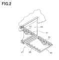
- Fig. 2 is an oblique view of the structure of a port of a stocker apparatus.
- the first-story port 41 is provided on the first-story side
- the second-story port 43 is provided on the second-story side.
- the containers 27 can be moved in and out through these ports 41 and 43.
- the first-story port 41 and the second-story port 43 each have an opening 45 that opens onto the outer face of the main body part 21, and a conveyor 47 provided on the inside and outside of the opening 45.
- the conveyor 47 includes an outer conveyor unit 49 arranged on the inside of the main body part 21, and an inner conveyor unit 51 arranged on the outside of the main part body 21.
- the outer conveyor unit 49 of each of the first-story port 41 and the second-story port 43 is supported by a hanger 55 from the ceiling.
- a ceiling transportation vehicle 59 that can travel along a rail 57 is provided to the ceiling above each outer conveyor unit 49.
- the ceiling transportation vehicle 59 carries the containers 27 from the outer conveyor unit 49, and carries the containers 27 back to the outer conveyor unit 49.
- the ceiling transportation vehicle 59 is controlled by a transportation vehicle controller 113 (described later).
- the conveyor units 49 and 51 are each configured such that a drive roller 61 and a driven roller 63 are attached to the left and right side faces of a square frame.
- the drive roller 61 is driven by a roller drive mechanism 103 ( Fig. 5 ).
- a placement sensor 107 for detecting the placement of a container 27 is provided to the outer conveyor unit 49.
- Positioning pins for the containers 27 may be provided to the outer conveyor unit 49, but need not be provided.
- Fig. 3 is a plan view of a container.
- the container 27 is used to hold substrates in a sealed state, and is conveyed by another apparatus.
- Each container 27 has a housing and a lid.
- a position adjustment mechanism (not shown) that is a groove into which a kinematic pin fits is provided to the bottom face of the container 27.
- a gas supply port 65 and an exhaust port 67 are formed in the bottom of the container 27, passing through the upper and lower faces.
- a one-way valve and a filter (not shown) are provided in the gas supply port 65 and the exhaust port 67, making contaminated outside air hardly flowing into the inside.
- FIG. 4 is a simplified diagram of a purging device.
- the purging device 73 is used to purge the container 27 with specific gases (such as N 2 or another such inert gas, or clean dry air).
- the purging device 73 is disposed below the outer conveyer unit 49, and purges the container 27 placed on the outer conveyer unit 49.
- the purging device 73 has an air supply tank 75, a gas supply pipe 77, and a gas supply nozzle 79.
- the air supply tank 75 contains clean dry air, for example.
- the gas supply pipe 77 extends from the air supply tank 75.
- the gas supply nozzle 79 is fixed to the distal end of the gas supply pipe 77.
- a flow control valve 81 and a shut-off valve 83 are provided along the gas supply pipe 77.
- the purging device 73 further has an exhaust pipe 84 and an exhaust nozzle 85.
- the exhaust nozzle 85 is fixed to the distal end of the exhaust pipe 84.
- the other end of the exhaust pipe 84 is guided to special processing equipment (not shown) by an exhaust device.
- seals are provided at the contact portions between the various members.
- the purging device 73 has a first lifting mechanism 87 for raising and lowering the gas supply nozzle 79.
- the first lifting mechanism 87 is an air cylinder mechanism, and has a rod 89 and a cylinder driver 91 that drives the rod 89.
- the first lifting mechanism 87 allows the gas supply nozzle 79 to move between a position of being disconnected from the gas supply port 65 and a position of being connected to the gas supply port 65.
- the purging device 73 has a second lifting mechanism 93 for raising and lowering the exhaust nozzle 85.
- the second lifting mechanism 93 is a cylinder mechanism, and has a rod 95 and a cylinder driver 97 that drives the rod 95.
- the second lifting mechanism 93 allows the exhaust nozzle 85 to move between a position of being disconnected from the exhaust port 67 and a position of being connected to the exhaust port 67.
- Fig. 5 is a block diagram of the control configuration of the stocker device 1.
- a stocker controller 101 is a computer having a CPU, RAM, ROM, and other such hardware, and performs various control operations by executing the commands of a program.
- the stocker controller 101 is connected to the stacker crane 25, the roller drive mechanism 103, the flow control valve 81, the shut-off valve 83, the first lifting mechanism 87, and the second lifting mechanism 93, and can transmit control signals to these.
- the stocker controller 101 is also connected to the placement sensor 107 and an ID reader 109, and is able to receive detection signals from these.
- the stocker controller 101 is connected so as to communicate with a distribution controller 111.
- the distribution controller 111 is a controller that is higher in level than the transportation vehicle controller 113 and the stocker controller 101.
- the distribution controller 111 Upon receiving a conveyance request from a manufacturing controller (not shown), if the conveyance request is attendant with retrieval at the stocker apparatus 1, the distribution controller 111 sends the stocker controller 101 a retrieval command at a specific timing.
- the distribution controller 111 also converts the received conveyance request into a conveyance command, and assigns this to the ceiling transportation vehicle 59.
- the stocker controller 101 is connected so as to communicate with the transportation vehicle controller 113.
- the transportation vehicle controller 113 manages the plurality of ceiling transportation vehicles 59, and has an assigning function to assign the conveyance commands to these. These conveyance commands include commands related to travelling, as well as commands related to pick-up and set-down positions.
- the distribution controller 111 sends the retrieval command to the stocker controller 101
- the stocker controller 101 performs a retrieval operation by controlling the stacker crane 25 and the roller drive mechanism 103.
- the distribution controller 111 also sends a conveyance command to the transportation vehicle controller 113.
- the transportation vehicle controller 113 assigns the conveyance command to the ceiling transportation vehicle 59.
- Fig. 6 is a flowchart of the control operation of a stocker apparatus.
- step S1 the stocker controller 101 waits for a retrieval command to be sent from the distribution controller 111.
- step S2 the stocker controller 101 moves a container 27 to the conveyor 47 by driving the stacker crane 25. More specifically, the stacker crane 25 takes the container 27 from the specific shelf 23A, and places the container 27 on the inner conveyor unit 51 of the conveyor unit of the port 41 or 43.
- step S3 the stocker controller 101 conveys the container 27 out of the main body part 21 with the conveyor 47 by driving the roller drive mechanism 103. More specifically, the conveyor unit 49 or 51 is driven in the outward direction, and the container 27 is moved on the outer conveyor unit 49.
- step S4 the stocker controller 101 waits for the container 27 to be positioned at the outer conveyor unit 49. Determining whether or not the container 27 is disposed on the outer conveyor unit 49 is based on a detection signal from the placement sensor 107.
- step S5 the stocker controller 101 drives the first lifting mechanism 87 and the second lifting mechanism 93 to raise the gas supply nozzle 79 and the exhaust nozzle 85, and connecting them to the gas supply port 65 and the exhaust port 67, respectively.
- the container 27 is positioned by raising also the kinematic pins (not shown) provided under the outer conveyer unit 49 at the same time. The positioning of the container 27 may also be accomplished by raising the kinematic pins prior to the raising of the gas supply nozzle 79 and the exhaust nozzle 85.
- step S6 the stocker controller 101 opens the shut-off valve 83. Consequently, clean dry air is supplied from the air supply tank 75 into the container 27.
- step S7 the stocker controller 101 waits for a signal to be sent from the transportation vehicle controller 113, indicating that the ceiling transportation vehicle 59 has arrived at the outer conveyor unit 49.
- step S8 the stocker controller 101 closes the shut-off valve 83. This stops the supply of clean dry air from the air supply tank 75 to the container 27. This operation is performed even if only a shorter time than the normal purge time has elapsed.
- step S9 the stocker controller 101 drives the first lifting mechanism 87 and the second lifting mechanism 93 to lower the gas supply nozzle 79 and the exhaust nozzle 85 and separate them from the gas supply port 65 and the exhaust port 67. In this way, the supply of purge gas can be stopped and the container 27 can be taken out as soon as the ceiling transportation vehicle 59 arrives. Therefore, it does not take any extra time to take out the container 27 with the ceiling transportation vehicle 59.
- the ceiling transportation vehicle 59 conveys the container 27 to the processing apparatus in the next step.
- the gas supply nozzle 79 and the exhaust nozzle 85 are connected to the gas supply port 65 and the exhaust port 67, respectively, by the first lifting mechanism 87 and the second lifting mechanism 93.
- the purging device 73 supplies purge gas to the container in this state.
- the stocker controller 101 then ascertains that the ceiling transportation vehicle 59 has arrived at the outer conveyor unit 49, the supply of the purge gas from the purging device 73 to the container 27 is stopped.
- the purge gas is supplied to the container 27 without any wasted waiting time, and loading by the ceiling transportation vehicle 59 can be carried out as fast as in the conventional technique. Also, there is no decrease in the purge gas concentration in the container 27 while the container 27 awaits loading onto the ceiling transportation vehicle 59.
- FIG. 7 and 8 are plan views of a container
- Fig. 9 is a simplified diagram of a purging device
- Fig. 10 is a block diagram of the control configuration of a stocker apparatus.
- Fig. 11 is a flowchart of the control operation of a stocker apparatus.
- the positions of the gas supply port 65' and the exhaust port 67' are shifted from the positions of the gas supply port 65 and the exhaust port 67 of the container 27 shown in the above-described embodiment.
- the positions of the gas supply port 65" and the exhaust port 67" are interchanged with the positions of the gas supply port 65 and the exhaust port 67 of the container 27 shown in the above-described embodiment.
- a purging device 73' will be described through reference to Fig. 9 .
- the basic structure of the purging device 73' is the same as that in the above embodiment, so only the parts that are different will be described here.
- the purging device 73' has a first table 121 and a second table 123.
- the first table 121 supports the first lifting mechanism 87 by an upper face thereof.
- the second table 123 supports the second lifting mechanism 93 by an upper face thereof.
- the first table 121 and the second table 123 are configured to move in all directions or in one direction within the horizontal plane.
- the first table 121 is driven by a first horizontal movement mechanism 125 ( Fig. 10 ).
- the second table 123 is driven by a second horizontal movement mechanism 127 ( Fig. 10 ).
- the first horizontal movement mechanism 125 and the second horizontal movement mechanism 127 may have any configuration, as long as they are configured to move the first table 121 and the second table 123 horizontally. For example, these may be solenoids, X-Y tables, or ball screw mechanisms.
- the stocker controller 101' has the first horizontal movement mechanism 125 and the second horizontal movement mechanism 127.
- Fig. 11 is a flowchart of the control operation of a stocker apparatus.
- steps S1 to S9 are the same as in the above-described embodiment, and therefore will not be described again here.
- steps S11 and S 12 are executed in between steps S4 and S5.
- step S11 the stocker controller 101' ascertains the type of container 27 on the basis of a detection signal from the ID reader 109, and then ascertains the positions of the gas supply port and exhaust port on the basis of the type of container 27.
- a sensor may specify the positions of the gas supply port and exhaust port, and send them to the stocker controller 101'.
- step S12 the stocker controller 101' drives the first horizontal movement mechanism 125 and the second horizontal movement mechanism 127 to position the gas supply nozzle 79 at the gas supply port 65, and to position the exhaust nozzle 85 at the exhaust port 67.
- the nozzle can be connected to the port even when a plurality of containers with different port positions are used.
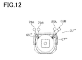
- Fig. 12 is a plan view of a container.
- the shapes of the gas supply port 65''' and the exhaust port 67''' are different from the shapes of the gas supply port 65 and the exhaust port 67 of the container 27 in the above-described embodiment.
- a first gas supply nozzle 79A and a second gas supply nozzle 79B are provided for the gas supply port 65''', and a first exhaust nozzle 85A and a second exhaust nozzle 85B are provided for the exhaust port 67'''.
- the first gas supply nozzle 79A and the second gas supply nozzle 79B have different shapes, and correspond to different types of gas supply port.
- the first exhaust nozzle 85A and the second exhaust nozzle 85B also have different shapes, and correspond to different types of exhaust port.
- the mechanism for raising and lowering the nozzles and the mechanism for moving them horizontally are the same as in the above-described embodiment.
- either the first gas supply nozzle 79A or the second gas supply nozzle 79B is connected to the gas supply port in accordance with the shape of the gas supply port. Also, either the first exhaust nozzle 85A or the second exhaust nozzle 85B is connected to the gas supply port in accordance with the shape of the exhaust port.
- the above-described position adjustment mechanism positions a plurality of nozzles with different shapes to the port of the container, these nozzles can be connected to the port even when a plurality of types of container having different port shapes are used.
- a load port device is a device for conveying a container having a gas port to a load position by the ceiling transportation vehicle 59, and includes the conveyor 47, the purging device 73, and the stocker controller 101.
- the conveyor 47 extends to the outer conveyor unit 49 (load position).
- the purging device 73 is arranged near the outer conveyor unit 4r9 and has the gas supply nozzle 79 (nozzle) configured to supply purge gas into a container 27 while connected to the gas port, and the first lifting mechanism 87 (moving mechanism) configured to move the gas supply nozzle 79 toward and away from the gas port.
- the stocker controller 101 is configured to control the purging device 73 to supply the purge gas into the container 27, and configured to stop supplying the purge gas into the container 27 based on an arrival of the ceiling transportation vehicle 59 to the outer conveyor unit 49.
- the gas supply nozzle 79 is connected to the gas supply port 65 by the first lifting mechanism 87, and the purging device 73 supplies the purge gas to the container 27 in this state. Then, after the stocker controller 101 ascertains that the ceiling transportation vehicle 59 has arrived at the outer conveyer unit 49, the supply of the purge gas from the purging device 73 to the container 27 is stopped. As a result, the purge gas is supplied to the container 27 without any wasted waiting time, and loading by the ceiling transportation vehicle 59 is also carried out as fast as in the conventional technique.
- the present invention can be applied to a load port device for conveying a container having a gas port and an internal space from a processing apparatus, and also to a conveyance system and a container conveyance method in which this load port device is used.
Applications Claiming Priority (2)
| Application Number | Priority Date | Filing Date | Title |
|---|---|---|---|
| JP2011116838 | 2011-05-25 | ||
| PCT/JP2012/060730 WO2012160917A1 (fr) | 2011-05-25 | 2012-04-20 | Appareil de port de chargement, système de transport et procédé de convoyage d'un conteneur |
Publications (3)
| Publication Number | Publication Date |
|---|---|
| EP2717306A1 true EP2717306A1 (fr) | 2014-04-09 |
| EP2717306A4 EP2717306A4 (fr) | 2014-11-26 |
| EP2717306B1 EP2717306B1 (fr) | 2020-09-16 |
Family
ID=47217001
Family Applications (1)
| Application Number | Title | Priority Date | Filing Date |
|---|---|---|---|
| EP12789538.1A Active EP2717306B1 (fr) | 2011-05-25 | 2012-04-20 | Appareil de port de chargement, système de transport et procédé de convoyage d'un conteneur |
Country Status (8)
| Country | Link |
|---|---|
| US (1) | US9701431B2 (fr) |
| EP (1) | EP2717306B1 (fr) |
| JP (1) | JP5700119B2 (fr) |
| KR (1) | KR101495629B1 (fr) |
| CN (1) | CN103548130B (fr) |
| SG (1) | SG194439A1 (fr) |
| TW (1) | TWI505391B (fr) |
| WO (1) | WO2012160917A1 (fr) |
Cited By (1)
| Publication number | Priority date | Publication date | Assignee | Title |
|---|---|---|---|---|
| EP3882181A4 (fr) * | 2018-12-26 | 2022-08-10 | Murata Machinery, Ltd. | Système d'entreposage |
Families Citing this family (18)
| Publication number | Priority date | Publication date | Assignee | Title |
|---|---|---|---|---|
| CN103922097A (zh) * | 2014-04-08 | 2014-07-16 | 上海华力微电子有限公司 | 搬运系统 |
| KR101608831B1 (ko) | 2014-06-13 | 2016-04-05 | 우범제 | 배출가속기 및 이를 구비한 로드 포트 |
| US9997387B2 (en) * | 2014-06-16 | 2018-06-12 | Murata Machinery, Ltd. | Purge device, purge system, purge method, and control method in purge system |
| SG11201700643UA (en) * | 2014-09-25 | 2017-04-27 | Murata Machinery Ltd | Purging device and purging method |
| JP6311579B2 (ja) * | 2014-11-12 | 2018-04-18 | 株式会社ダイフク | 物品搬送設備 |
| KR101609338B1 (ko) | 2015-03-16 | 2016-04-05 | 크린팩토메이션 주식회사 | 웨이퍼 캐리어를 천정에 보관하고 처리하는 장치 |
| JP6459682B2 (ja) * | 2015-03-20 | 2019-01-30 | Tdk株式会社 | ガスパージ装置、ロードポート装置およびガスパージ方法 |
| JP6358143B2 (ja) * | 2015-03-26 | 2018-07-18 | 株式会社ダイフク | 半導体容器保管設備 |
| JP6554872B2 (ja) * | 2015-03-31 | 2019-08-07 | Tdk株式会社 | ガスパージ装置、ロードポート装置、パージ対象容器の設置台およびガスパージ方法 |
| SG11201801385XA (en) * | 2015-08-28 | 2018-03-28 | Murata Machinery Ltd | Storage apparatus and storage method |
| JP6561700B2 (ja) * | 2015-09-04 | 2019-08-21 | シンフォニアテクノロジー株式会社 | ガス注入装置 |
| JP6455404B2 (ja) * | 2015-11-17 | 2019-01-23 | 株式会社ダイフク | 容器搬送設備 |
| JP6766584B2 (ja) | 2016-10-19 | 2020-10-14 | 株式会社ダイフク | 物品搬送設備 |
| EP3655324A4 (fr) * | 2017-07-21 | 2021-04-21 | Sentien Robotics, Inc. | Système de déploiement et récupération de véhicule aérien sans pilote |
| CN112074470B (zh) * | 2018-05-23 | 2022-07-15 | 株式会社大福 | 拣选系统 |
| CN114365271A (zh) * | 2019-11-05 | 2022-04-15 | 村田机械株式会社 | 输送车系统 |
| JP7422577B2 (ja) * | 2020-03-23 | 2024-01-26 | 平田機工株式会社 | ロードポート及び制御方法 |
| JP2020115591A (ja) * | 2020-04-30 | 2020-07-30 | Tdk株式会社 | フープロードポート装置 |
Citations (5)
| Publication number | Priority date | Publication date | Assignee | Title |
|---|---|---|---|---|
| JP2000077490A (ja) * | 1998-09-01 | 2000-03-14 | Seiko Instruments Inc | 半導体ウェハー観察装置 |
| JP2006228808A (ja) * | 2005-02-15 | 2006-08-31 | Seiko Epson Corp | 基板搬送装置、基板搬送方法及び半導体製造装置 |
| US20090062956A1 (en) * | 2007-08-28 | 2009-03-05 | Taiwan Semiconductor Manufacturing Co., Ltd. | Method and structure for automated inert gas charging in a reticle stocker |
| US20090159151A1 (en) * | 2007-12-20 | 2009-06-25 | Wang Sheng-Hung | Gas filling apparatus |
| US20100135753A1 (en) * | 2008-12-02 | 2010-06-03 | Sinfonia Technology Co., Ltd. | Load port |
Family Cites Families (22)
| Publication number | Priority date | Publication date | Assignee | Title |
|---|---|---|---|---|
| ES2078718T3 (es) * | 1992-08-04 | 1995-12-16 | Ibm | Estructuras de cadenas de fabricacion a base de transportadores totalmente automatizados e informatizados adaptados a recipientes transportables estancos a presion. |
| US5988233A (en) * | 1998-03-27 | 1999-11-23 | Asyst Technologies, Inc. | Evacuation-driven SMIF pod purge system |
| JP3697478B2 (ja) * | 2001-08-20 | 2005-09-21 | ソニー株式会社 | 基板の移送方法及びロードポート装置並びに基板移送システム |
| US6726429B2 (en) * | 2002-02-19 | 2004-04-27 | Vertical Solutions, Inc. | Local store for a wafer processing station |
| US6881020B2 (en) * | 2002-04-26 | 2005-04-19 | Taiwan Semiconductor Manufacturing Co., Ltd | Pod transfer system having retractable mast and rotatable and vertically movable hoist |
| JP3832745B2 (ja) * | 2003-02-10 | 2006-10-11 | 村田機械株式会社 | 天井走行車システム |
| TWI246501B (en) * | 2003-02-03 | 2006-01-01 | Murata Machinery Ltd | Overhead traveling carriage system |
| JP3902583B2 (ja) * | 2003-09-25 | 2007-04-11 | Tdk株式会社 | 可搬式密閉容器内部のパージシステムおよびパージ方法 |
| WO2005101484A1 (fr) * | 2004-04-07 | 2005-10-27 | Right Mfg Co. Ltd. | Dispositif de raccord pour orifices de renouvellement d'atmosphère pour récipients de stockage de substrats |
| JP4585514B2 (ja) * | 2004-06-21 | 2010-11-24 | 株式会社ライト製作所 | ロードポート |
| JP4271095B2 (ja) * | 2004-07-15 | 2009-06-03 | 東京エレクトロン株式会社 | 基板加熱装置及び基板加熱方法 |
| CN101138079A (zh) * | 2004-11-09 | 2008-03-05 | 株式会社来易特制作所 | 载入机以及转接器 |
| JP3983254B2 (ja) * | 2005-06-24 | 2007-09-26 | Tdk株式会社 | 製品収容容器用パージシステム及び該パージシステムに供せられる台 |
| JP4527670B2 (ja) * | 2006-01-25 | 2010-08-18 | 東京エレクトロン株式会社 | 加熱処理装置、加熱処理方法、制御プログラムおよびコンピュータ読取可能な記憶媒体 |
| JP4984819B2 (ja) * | 2006-10-24 | 2012-07-25 | 信越半導体株式会社 | 基板出荷ボックスの識別システム |
| JP5003292B2 (ja) * | 2006-11-07 | 2012-08-15 | シンフォニアテクノロジー株式会社 | 搬送システム |
| JP4859229B2 (ja) * | 2006-12-08 | 2012-01-25 | 東京エレクトロン株式会社 | 熱処理装置 |
| JP4670808B2 (ja) * | 2006-12-22 | 2011-04-13 | ムラテックオートメーション株式会社 | コンテナの搬送システム及び測定用コンテナ |
| JP4692584B2 (ja) * | 2008-07-03 | 2011-06-01 | 村田機械株式会社 | パージ装置 |
| JP5309814B2 (ja) | 2008-09-08 | 2013-10-09 | 村田機械株式会社 | 搬送車システム |
| US8287648B2 (en) * | 2009-02-09 | 2012-10-16 | Asm America, Inc. | Method and apparatus for minimizing contamination in semiconductor processing chamber |
| JP2011187539A (ja) * | 2010-03-05 | 2011-09-22 | Sinfonia Technology Co Ltd | ガス注入装置、ガス排出装置、ガス注入方法及びガス排出方法 |
-
2012
- 2012-04-20 CN CN201280024471.5A patent/CN103548130B/zh active Active
- 2012-04-20 JP JP2013516254A patent/JP5700119B2/ja active Active
- 2012-04-20 KR KR1020137032925A patent/KR101495629B1/ko active IP Right Grant
- 2012-04-20 WO PCT/JP2012/060730 patent/WO2012160917A1/fr active Application Filing
- 2012-04-20 US US14/118,897 patent/US9701431B2/en active Active
- 2012-04-20 SG SG2013073002A patent/SG194439A1/en unknown
- 2012-04-20 EP EP12789538.1A patent/EP2717306B1/fr active Active
- 2012-05-25 TW TW101118663A patent/TWI505391B/zh active
Patent Citations (5)
| Publication number | Priority date | Publication date | Assignee | Title |
|---|---|---|---|---|
| JP2000077490A (ja) * | 1998-09-01 | 2000-03-14 | Seiko Instruments Inc | 半導体ウェハー観察装置 |
| JP2006228808A (ja) * | 2005-02-15 | 2006-08-31 | Seiko Epson Corp | 基板搬送装置、基板搬送方法及び半導体製造装置 |
| US20090062956A1 (en) * | 2007-08-28 | 2009-03-05 | Taiwan Semiconductor Manufacturing Co., Ltd. | Method and structure for automated inert gas charging in a reticle stocker |
| US20090159151A1 (en) * | 2007-12-20 | 2009-06-25 | Wang Sheng-Hung | Gas filling apparatus |
| US20100135753A1 (en) * | 2008-12-02 | 2010-06-03 | Sinfonia Technology Co., Ltd. | Load port |
Non-Patent Citations (1)
| Title |
|---|
| See also references of WO2012160917A1 * |
Cited By (1)
| Publication number | Priority date | Publication date | Assignee | Title |
|---|---|---|---|---|
| EP3882181A4 (fr) * | 2018-12-26 | 2022-08-10 | Murata Machinery, Ltd. | Système d'entreposage |
Also Published As
| Publication number | Publication date |
|---|---|
| EP2717306A4 (fr) | 2014-11-26 |
| KR101495629B1 (ko) | 2015-02-25 |
| EP2717306B1 (fr) | 2020-09-16 |
| US20140109516A1 (en) | 2014-04-24 |
| KR20140010984A (ko) | 2014-01-27 |
| JP5700119B2 (ja) | 2015-04-15 |
| CN103548130A (zh) | 2014-01-29 |
| CN103548130B (zh) | 2016-08-17 |
| SG194439A1 (en) | 2013-12-30 |
| TW201249731A (en) | 2012-12-16 |
| US9701431B2 (en) | 2017-07-11 |
| JPWO2012160917A1 (ja) | 2014-07-31 |
| TWI505391B (zh) | 2015-10-21 |
| WO2012160917A1 (fr) | 2012-11-29 |
Similar Documents
| Publication | Publication Date | Title |
|---|---|---|
| EP2717306B1 (fr) | Appareil de port de chargement, système de transport et procédé de convoyage d'un conteneur | |
| US9991144B2 (en) | Storage warehouse | |
| US7753639B2 (en) | Overhead travelling carriage system | |
| KR101942394B1 (ko) | 퍼지 장치 및 퍼지 방법 | |
| WO2011083525A1 (fr) | Système de véhicule de transfert | |
| CN108290687B (zh) | 保管装置以及输送系统 | |
| JP2008019017A (ja) | 物品収納装置 | |
| US7806648B2 (en) | Transportation system and transportation method | |
| US20090022575A1 (en) | Article storing apparatus | |
| WO2013150841A1 (fr) | Système de transport | |
| JP2010013250A (ja) | 搬送システム及びコンピュータプログラム | |
| JP2008044729A (ja) | 自動倉庫及び入出庫管理方法 | |
| CN115072252A (zh) | 物品搬送设备 | |
| JP2009035413A (ja) | 工程間搬送システム |
Legal Events
| Date | Code | Title | Description |
|---|---|---|---|
| PUAI | Public reference made under article 153(3) epc to a published international application that has entered the european phase |
Free format text: ORIGINAL CODE: 0009012 |
|
| 17P | Request for examination filed |
Effective date: 20131121 |
|
| AK | Designated contracting states |
Kind code of ref document: A1 Designated state(s): AL AT BE BG CH CY CZ DE DK EE ES FI FR GB GR HR HU IE IS IT LI LT LU LV MC MK MT NL NO PL PT RO RS SE SI SK SM TR |
|
| DAX | Request for extension of the european patent (deleted) | ||
| A4 | Supplementary search report drawn up and despatched |
Effective date: 20141024 |
|
| RIC1 | Information provided on ipc code assigned before grant |
Ipc: H01L 21/673 20060101ALI20141020BHEP Ipc: B65B 31/04 20060101ALI20141020BHEP Ipc: H01L 21/677 20060101AFI20141020BHEP Ipc: B65G 1/00 20060101ALI20141020BHEP Ipc: B65G 1/04 20060101ALI20141020BHEP |
|
| GRAP | Despatch of communication of intention to grant a patent |
Free format text: ORIGINAL CODE: EPIDOSNIGR1 |
|
| STAA | Information on the status of an ep patent application or granted ep patent |
Free format text: STATUS: GRANT OF PATENT IS INTENDED |
|
| INTG | Intention to grant announced |
Effective date: 20200408 |
|
| GRAS | Grant fee paid |
Free format text: ORIGINAL CODE: EPIDOSNIGR3 |
|
| GRAA | (expected) grant |
Free format text: ORIGINAL CODE: 0009210 |
|
| STAA | Information on the status of an ep patent application or granted ep patent |
Free format text: STATUS: THE PATENT HAS BEEN GRANTED |
|
| AK | Designated contracting states |
Kind code of ref document: B1 Designated state(s): AL AT BE BG CH CY CZ DE DK EE ES FI FR GB GR HR HU IE IS IT LI LT LU LV MC MK MT NL NO PL PT RO RS SE SI SK SM TR |
|
| REG | Reference to a national code |
Ref country code: GB Ref legal event code: FG4D |
|
| REG | Reference to a national code |
Ref country code: CH Ref legal event code: EP |
|
| REG | Reference to a national code |
Ref country code: DE Ref legal event code: R096 Ref document number: 602012072362 Country of ref document: DE |
|
| REG | Reference to a national code |
Ref country code: IE Ref legal event code: FG4D |
|
| REG | Reference to a national code |
Ref country code: AT Ref legal event code: REF Ref document number: 1314920 Country of ref document: AT Kind code of ref document: T Effective date: 20201015 |
|
| PG25 | Lapsed in a contracting state [announced via postgrant information from national office to epo] |
Ref country code: FI Free format text: LAPSE BECAUSE OF FAILURE TO SUBMIT A TRANSLATION OF THE DESCRIPTION OR TO PAY THE FEE WITHIN THE PRESCRIBED TIME-LIMIT Effective date: 20200916 Ref country code: NO Free format text: LAPSE BECAUSE OF FAILURE TO SUBMIT A TRANSLATION OF THE DESCRIPTION OR TO PAY THE FEE WITHIN THE PRESCRIBED TIME-LIMIT Effective date: 20201216 Ref country code: BG Free format text: LAPSE BECAUSE OF FAILURE TO SUBMIT A TRANSLATION OF THE DESCRIPTION OR TO PAY THE FEE WITHIN THE PRESCRIBED TIME-LIMIT Effective date: 20201216 Ref country code: GR Free format text: LAPSE BECAUSE OF FAILURE TO SUBMIT A TRANSLATION OF THE DESCRIPTION OR TO PAY THE FEE WITHIN THE PRESCRIBED TIME-LIMIT Effective date: 20201217 Ref country code: HR Free format text: LAPSE BECAUSE OF FAILURE TO SUBMIT A TRANSLATION OF THE DESCRIPTION OR TO PAY THE FEE WITHIN THE PRESCRIBED TIME-LIMIT Effective date: 20200916 Ref country code: SE Free format text: LAPSE BECAUSE OF FAILURE TO SUBMIT A TRANSLATION OF THE DESCRIPTION OR TO PAY THE FEE WITHIN THE PRESCRIBED TIME-LIMIT Effective date: 20200916 |
|
| REG | Reference to a national code |
Ref country code: AT Ref legal event code: MK05 Ref document number: 1314920 Country of ref document: AT Kind code of ref document: T Effective date: 20200916 |
|
| REG | Reference to a national code |
Ref country code: NL Ref legal event code: MP Effective date: 20200916 |
|
| PG25 | Lapsed in a contracting state [announced via postgrant information from national office to epo] |
Ref country code: RS Free format text: LAPSE BECAUSE OF FAILURE TO SUBMIT A TRANSLATION OF THE DESCRIPTION OR TO PAY THE FEE WITHIN THE PRESCRIBED TIME-LIMIT Effective date: 20200916 Ref country code: LV Free format text: LAPSE BECAUSE OF FAILURE TO SUBMIT A TRANSLATION OF THE DESCRIPTION OR TO PAY THE FEE WITHIN THE PRESCRIBED TIME-LIMIT Effective date: 20200916 |
|
| REG | Reference to a national code |
Ref country code: LT Ref legal event code: MG4D |
|
| PG25 | Lapsed in a contracting state [announced via postgrant information from national office to epo] |
Ref country code: CZ Free format text: LAPSE BECAUSE OF FAILURE TO SUBMIT A TRANSLATION OF THE DESCRIPTION OR TO PAY THE FEE WITHIN THE PRESCRIBED TIME-LIMIT Effective date: 20200916 Ref country code: EE Free format text: LAPSE BECAUSE OF FAILURE TO SUBMIT A TRANSLATION OF THE DESCRIPTION OR TO PAY THE FEE WITHIN THE PRESCRIBED TIME-LIMIT Effective date: 20200916 Ref country code: RO Free format text: LAPSE BECAUSE OF FAILURE TO SUBMIT A TRANSLATION OF THE DESCRIPTION OR TO PAY THE FEE WITHIN THE PRESCRIBED TIME-LIMIT Effective date: 20200916 Ref country code: SM Free format text: LAPSE BECAUSE OF FAILURE TO SUBMIT A TRANSLATION OF THE DESCRIPTION OR TO PAY THE FEE WITHIN THE PRESCRIBED TIME-LIMIT Effective date: 20200916 Ref country code: PT Free format text: LAPSE BECAUSE OF FAILURE TO SUBMIT A TRANSLATION OF THE DESCRIPTION OR TO PAY THE FEE WITHIN THE PRESCRIBED TIME-LIMIT Effective date: 20210118 Ref country code: LT Free format text: LAPSE BECAUSE OF FAILURE TO SUBMIT A TRANSLATION OF THE DESCRIPTION OR TO PAY THE FEE WITHIN THE PRESCRIBED TIME-LIMIT Effective date: 20200916 Ref country code: NL Free format text: LAPSE BECAUSE OF FAILURE TO SUBMIT A TRANSLATION OF THE DESCRIPTION OR TO PAY THE FEE WITHIN THE PRESCRIBED TIME-LIMIT Effective date: 20200916 |
|
| PG25 | Lapsed in a contracting state [announced via postgrant information from national office to epo] |
Ref country code: AT Free format text: LAPSE BECAUSE OF FAILURE TO SUBMIT A TRANSLATION OF THE DESCRIPTION OR TO PAY THE FEE WITHIN THE PRESCRIBED TIME-LIMIT Effective date: 20200916 Ref country code: AL Free format text: LAPSE BECAUSE OF FAILURE TO SUBMIT A TRANSLATION OF THE DESCRIPTION OR TO PAY THE FEE WITHIN THE PRESCRIBED TIME-LIMIT Effective date: 20200916 Ref country code: ES Free format text: LAPSE BECAUSE OF FAILURE TO SUBMIT A TRANSLATION OF THE DESCRIPTION OR TO PAY THE FEE WITHIN THE PRESCRIBED TIME-LIMIT Effective date: 20200916 Ref country code: IS Free format text: LAPSE BECAUSE OF FAILURE TO SUBMIT A TRANSLATION OF THE DESCRIPTION OR TO PAY THE FEE WITHIN THE PRESCRIBED TIME-LIMIT Effective date: 20210116 Ref country code: PL Free format text: LAPSE BECAUSE OF FAILURE TO SUBMIT A TRANSLATION OF THE DESCRIPTION OR TO PAY THE FEE WITHIN THE PRESCRIBED TIME-LIMIT Effective date: 20200916 |
|
| REG | Reference to a national code |
Ref country code: DE Ref legal event code: R097 Ref document number: 602012072362 Country of ref document: DE |
|
| PG25 | Lapsed in a contracting state [announced via postgrant information from national office to epo] |
Ref country code: SK Free format text: LAPSE BECAUSE OF FAILURE TO SUBMIT A TRANSLATION OF THE DESCRIPTION OR TO PAY THE FEE WITHIN THE PRESCRIBED TIME-LIMIT Effective date: 20200916 |
|
| PLBE | No opposition filed within time limit |
Free format text: ORIGINAL CODE: 0009261 |
|
| STAA | Information on the status of an ep patent application or granted ep patent |
Free format text: STATUS: NO OPPOSITION FILED WITHIN TIME LIMIT |
|
| 26N | No opposition filed |
Effective date: 20210617 |
|
| PG25 | Lapsed in a contracting state [announced via postgrant information from national office to epo] |
Ref country code: SI Free format text: LAPSE BECAUSE OF FAILURE TO SUBMIT A TRANSLATION OF THE DESCRIPTION OR TO PAY THE FEE WITHIN THE PRESCRIBED TIME-LIMIT Effective date: 20200916 Ref country code: DK Free format text: LAPSE BECAUSE OF FAILURE TO SUBMIT A TRANSLATION OF THE DESCRIPTION OR TO PAY THE FEE WITHIN THE PRESCRIBED TIME-LIMIT Effective date: 20200916 |
|
| PG25 | Lapsed in a contracting state [announced via postgrant information from national office to epo] |
Ref country code: IT Free format text: LAPSE BECAUSE OF FAILURE TO SUBMIT A TRANSLATION OF THE DESCRIPTION OR TO PAY THE FEE WITHIN THE PRESCRIBED TIME-LIMIT Effective date: 20200916 |
|
| PG25 | Lapsed in a contracting state [announced via postgrant information from national office to epo] |
Ref country code: MC Free format text: LAPSE BECAUSE OF FAILURE TO SUBMIT A TRANSLATION OF THE DESCRIPTION OR TO PAY THE FEE WITHIN THE PRESCRIBED TIME-LIMIT Effective date: 20200916 |
|
| GBPC | Gb: european patent ceased through non-payment of renewal fee |
Effective date: 20210420 |
|
| PG25 | Lapsed in a contracting state [announced via postgrant information from national office to epo] |
Ref country code: LU Free format text: LAPSE BECAUSE OF NON-PAYMENT OF DUE FEES Effective date: 20210420 |
|
| REG | Reference to a national code |
Ref country code: BE Ref legal event code: MM Effective date: 20210430 |
|
| PG25 | Lapsed in a contracting state [announced via postgrant information from national office to epo] |
Ref country code: GB Free format text: LAPSE BECAUSE OF NON-PAYMENT OF DUE FEES Effective date: 20210420 Ref country code: FR Free format text: LAPSE BECAUSE OF NON-PAYMENT OF DUE FEES Effective date: 20210430 Ref country code: LI Free format text: LAPSE BECAUSE OF NON-PAYMENT OF DUE FEES Effective date: 20210430 Ref country code: CH Free format text: LAPSE BECAUSE OF NON-PAYMENT OF DUE FEES Effective date: 20210430 |
|
| PG25 | Lapsed in a contracting state [announced via postgrant information from national office to epo] |
Ref country code: IS Free format text: LAPSE BECAUSE OF FAILURE TO SUBMIT A TRANSLATION OF THE DESCRIPTION OR TO PAY THE FEE WITHIN THE PRESCRIBED TIME-LIMIT Effective date: 20210116 |
|
| PG25 | Lapsed in a contracting state [announced via postgrant information from national office to epo] |
Ref country code: BE Free format text: LAPSE BECAUSE OF NON-PAYMENT OF DUE FEES Effective date: 20210430 |
|
| PG25 | Lapsed in a contracting state [announced via postgrant information from national office to epo] |
Ref country code: HU Free format text: LAPSE BECAUSE OF FAILURE TO SUBMIT A TRANSLATION OF THE DESCRIPTION OR TO PAY THE FEE WITHIN THE PRESCRIBED TIME-LIMIT; INVALID AB INITIO Effective date: 20120420 Ref country code: CY Free format text: LAPSE BECAUSE OF FAILURE TO SUBMIT A TRANSLATION OF THE DESCRIPTION OR TO PAY THE FEE WITHIN THE PRESCRIBED TIME-LIMIT Effective date: 20200916 |
|
| PGFP | Annual fee paid to national office [announced via postgrant information from national office to epo] |
Ref country code: IE Payment date: 20230419 Year of fee payment: 12 Ref country code: DE Payment date: 20230420 Year of fee payment: 12 |
|
| PGFP | Annual fee paid to national office [announced via postgrant information from national office to epo] |
Ref country code: IE Payment date: 20240322 Year of fee payment: 13 |