EP2712380B1 - Aussteller für kraftfahrzeugtüren und -klappen - Google Patents
Aussteller für kraftfahrzeugtüren und -klappen Download PDFInfo
- Publication number
- EP2712380B1 EP2712380B1 EP12727247.4A EP12727247A EP2712380B1 EP 2712380 B1 EP2712380 B1 EP 2712380B1 EP 12727247 A EP12727247 A EP 12727247A EP 2712380 B1 EP2712380 B1 EP 2712380B1
- Authority
- EP
- European Patent Office
- Prior art keywords
- lever
- positioning element
- outside
- element according
- drive
- Prior art date
- Legal status (The legal status is an assumption and is not a legal conclusion. Google has not performed a legal analysis and makes no representation as to the accuracy of the status listed.)
- Active
Links
- 239000002184 metal Substances 0.000 claims description 3
- 229920003023 plastic Polymers 0.000 claims description 3
- 239000004033 plastic Substances 0.000 claims description 3
- 206010037660 Pyrexia Diseases 0.000 claims 1
- 238000009412 basement excavation Methods 0.000 description 10
- 238000000034 method Methods 0.000 description 4
- 238000000926 separation method Methods 0.000 description 2
- 230000015572 biosynthetic process Effects 0.000 description 1
- 230000008878 coupling Effects 0.000 description 1
- 238000010168 coupling process Methods 0.000 description 1
- 238000005859 coupling reaction Methods 0.000 description 1
- 238000007789 sealing Methods 0.000 description 1
Images

Classifications
-
- E—FIXED CONSTRUCTIONS
- E05—LOCKS; KEYS; WINDOW OR DOOR FITTINGS; SAFES
- E05B—LOCKS; ACCESSORIES THEREFOR; HANDCUFFS
- E05B83/00—Vehicle locks specially adapted for particular types of wing or vehicle
- E05B83/16—Locks for luggage compartments, car boot lids or car bonnets
- E05B83/18—Locks for luggage compartments, car boot lids or car bonnets for car boot lids or rear luggage compartments
-
- E—FIXED CONSTRUCTIONS
- E05—LOCKS; KEYS; WINDOW OR DOOR FITTINGS; SAFES
- E05F—DEVICES FOR MOVING WINGS INTO OPEN OR CLOSED POSITION; CHECKS FOR WINGS; WING FITTINGS NOT OTHERWISE PROVIDED FOR, CONCERNED WITH THE FUNCTIONING OF THE WING
- E05F15/00—Power-operated mechanisms for wings
- E05F15/60—Power-operated mechanisms for wings using electrical actuators
-
- E—FIXED CONSTRUCTIONS
- E05—LOCKS; KEYS; WINDOW OR DOOR FITTINGS; SAFES
- E05B—LOCKS; ACCESSORIES THEREFOR; HANDCUFFS
- E05B81/00—Power-actuated vehicle locks
- E05B81/12—Power-actuated vehicle locks characterised by the function or purpose of the powered actuators
- E05B81/20—Power-actuated vehicle locks characterised by the function or purpose of the powered actuators for assisting final closing or for initiating opening
-
- E—FIXED CONSTRUCTIONS
- E05—LOCKS; KEYS; WINDOW OR DOOR FITTINGS; SAFES
- E05C—BOLTS OR FASTENING DEVICES FOR WINGS, SPECIALLY FOR DOORS OR WINDOWS
- E05C3/00—Fastening devices with bolts moving pivotally or rotatively
- E05C3/12—Fastening devices with bolts moving pivotally or rotatively with latching action
-
- E—FIXED CONSTRUCTIONS
- E05—LOCKS; KEYS; WINDOW OR DOOR FITTINGS; SAFES
- E05F—DEVICES FOR MOVING WINGS INTO OPEN OR CLOSED POSITION; CHECKS FOR WINGS; WING FITTINGS NOT OTHERWISE PROVIDED FOR, CONCERNED WITH THE FUNCTIONING OF THE WING
- E05F7/00—Accessories for wings not provided for in other groups of this subclass
- E05F7/005—Aligning devices for wings
Definitions
- the invention relates to an exhibitor for motor vehicle doors and flaps, in particular for the trunk and tailgates of passenger vehicles with or without operating handle, which is pivotable between a closed position and a lifting position and has an activated by the unlocking of the lock of the flap lifting element, which Flap motor in the excavation position pivoting and then switched back to the closed position.
- the DE 198 35 994 B4 shows and describes an actuator for a flap, in particular for the tailgate of a motor vehicle, in which the flap is pivoted via a so-called ejector device to form a gap so that through this gap through the flap can be taken and opened. It is additionally provided a handle which can be pivoted automatically only after unlocking the lock from a retracted rest position to a working position.
- Auswerfer serves a rod with a rack-like design in which a gear meshes, which is driven by a spindle nut.
- a corresponding closure consisting of a rotary latch and a pawl and a corresponding pawl drive is formed so that the catch is brought by means of the pawl drive in an opening to form a gap excavating position.
- a pawl drive which can control the catch via a rigid connecting lever in the context of a forced operation in an excavation position.
- Comparable versions are from the US 5,020,838 A and the DE 298 13 797 U1 known.
- the DE 298 12 121 U1 describes an exhibitor for tailgates, hoods and Like, in which a gap between the seal and the counter-sealing surface is generated via a lifting member which is piloted by a common drive of the handle extension.
- the invention is therefore based on the object to propose an exhibitor who survives an immediate re-slam the vehicle door without prejudice.
- the lifting element is formed in two parts and having an outer and an inner lever which are pivotally or slidably relative to each other and releasably connected to a drive lever rotatably mounted drive element, wherein the inner lever against the Clockwise and the outer lever clockwise active are designed to pivot back.
- Such a trained exhibitor can be initially advantageously fixed to the inner wall of the covered by the flap interior and arranged so that it is beautifully housed and at the same time does not constitute a hindrance when loading or unloading the interior. He is not direct housed on or in the lock housing, but rather can be specifically housed in an area where there is space for it. It is connected via a rod or the like with the drive element and thus with the outer lever, so that in a simple manner the outer lever can be brought together with the inner lever from the basic position to a first Aushub too.
- the outer lever is formed in the clockwise direction and the inner lever counterclockwise active gurschwenkend, preferably they are spring loaded accordingly.
- the inner lever is detachable from the outer lever and the drive element, so that it can be further pivoted after reaching a first Aushub too to bring the flap really in the open state. Thereafter, the outer lever is then pivoted together with the inner lever in a clockwise direction and indeed back to the normal position, so that it is no longer influenced by the possible slamming of the flap and can not be damaged. Overall, an exhibitor is thus created, which performs the movements including the pivoting back in quick succession and so automated that errors can not occur.
- the inner lever and outer lever are spring loaded.
- the inner lever is opposite and the outer lever spring-loaded clockwise, so that with the help of the spring-loaded inner lever after separating both levers from each other and the drive element, the inner lever alone can be pivoted on the spring, so as to achieve the final open position for the flap or to cause the flap to be pushed up to this position.
- the outer lever is pivoted together with the inner lever clockwise and that back to the normal position, so that it can not be damaged by the possible slamming the flap.
- the spring load ensures a simple and permanently safe active pivoting of both levers.
- the inner lever at one or better said in the relative movement relative to the outer lever, the drive element, as Drive pawl is executed, over a stop cam of the outer lever and thus releasably shaped by the drive element.
- the inner lever is the outer lever partially comprising and formed a stop ring.
- the outer lever is thus practically in the inner lever and in such a way that it once on the one stop ring takes the inner lever when swinging and on the other hand ensures over the stop ring that the inner lever can be swung back against its associated spring force.
- the outer lever has a greater spring load than the inner lever and that by 20 - 60% greater spring load.
- the spring load can be selected for both levers. In any case, it is ensured that after pivoting of the inner lever in the second excavation position on the associated spring force then after releasing the connection of outer lever and inner lever of the outer lever on the spring load acting on it simultaneously with the inner lever and in the original basic position swings back. The exhibitor will then be available again for the next opening procedure.
- a safe influence of the drive element on the outer lever and thus simultaneously on the inner lever is ensured by the fact that the outer lever has a drive element receiving recess and the drive element a corresponding locking lug.
- the drive element With the beginning of the opening process of the drive via the drive element acts on the outer lever, that the drive element is inserted with the corresponding locking lug in the recess of the outer lever.
- the recess and the detent are aligned and shaped so that the contact between the drive element and the outer lever and thus inner lever is maintained during the following movement process.
- the two components are shaped so that they are separated via the inner lever at a given time from each other, that then the inner lever can be further pivoted on the spring force.
- the invention preferably provides that the inner lever when reaching the second Aushub too the drive on the return to the normal position appealing and thereby releasing the return spring of the outer lever is switched. So as soon as the inner lever has reached the second Aushub too and thereby the contact between the drive and the outer lever is no longer given, the drive is switched off or switched so that it does not hinder the return to the normal position, so that quickly by the installed spring force this return movement and can be carried out evenly without allowing the least danger to the exhibitor.
- the outer lever according to the invention consists of metal and the inner lever with the stop ring made of plastic. It is advantageous that the outer lever surrounding the inner lever is made of plastic, so then can be easily brought into connection with the flap without causing any scratches or the like there. By contrast, the outer lever transmitting the essential force is made of metal.
- the invention is characterized in particular by the fact that an exhibitor is created, which allows a safe operation, for example, the trunk lid or the tailgate of a passenger car with or without operating handle.
- the lifting element With actuation of the lock of the flap, the lifting element is active, which then ensures that the drive element pivots the outer and inner levers in the first excavation position. This is done at short notice and then the desired gap formation is present, which makes it possible to unlock the flap or bonnet and then legislativeschwenken total.
- the spring load on the inner lever which is separated from the outer lever, brought into a position which is referred to as a second excavation position and makes the automatic or manually effected complete opening of the flap is possible.
- the outer lever can now be swung back under the entrainment of the inner lever via its spring in the basic position, whereupon the closed position is then reached again via the drive. All of this can be done relatively quickly and ensures that even if the flap or a door accidentally or deliberately slammed again very quickly, the exhibitor is not damaged or otherwise negatively affected.
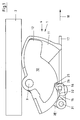
- FIG. 1 shows an exhibitor 1, as it is installed for example in a motor vehicle to bring the only indicated here and designated 2 flap in a gap position, then finally unlock the flap 2 and swing open. 3, the pivot axis is referred to the exhibitor 1 can be pivoted about its lifting element 10.
- the so-called closed position 4 is reproduced, ie the flap 2 rests on the upper edge 8 of the opening.
- the lifting element 10 is formed in two parts and consists of the inner lever 11 and the outer lever 12, wherein the inner lever 11 includes the outer lever 12 partially.
- the outer lever 12 is detachably connected to the drive element 16 and thus the drive 17.
- the drive element 16, here in the form of a drive pawl 15 is on the rod-shaped drive 17 from the in FIG. 1 shown position in the off FIG. 2 apparent position.
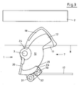
- the locking lug 26 is then pressed into the recess 25 in the outer lever 12, so that at the same time with the pivoting of the drive pawl 15 and the outer lever 12 and the inner lever 11 are moved and pivoted.
- the drive 17, here a kind of rod, is moved in the pulling direction 18, so that the drive element 16 and the drive pawl 15 from the position in FIG from FIG. 2 moved apparent position, ie pivoted about the pivot axis 3.
- the outer lever 12 pushes the flap 2 high, so that the gap 9 is formed.
- the outer lever 12 takes the inner lever 11, wherein the stop ring 19 is responsible for taking along the inner lever 11.
- the stop ring 19 is as recognizable much larger than the stop ring 20, which is responsible for the return stroke.
- the so-called upward stroke 21 is reproduced, which is completed after reaching the first excavation position 6.
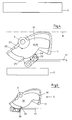
- FIG. 3 is the second lifting movement again, which serves to separate the two levers 11, 12 and the drive member 16 from each other, wherein the relative movement of the inner lever 11 relative to the outer lever 12 of the inner lever 11 with its outer edge arc 32 meets the stop cam 30 and thereby ensures that the drive pawl 15 and the drive member 16 and the levers 11,12 are separated from each other.
- the latching lug 26 of the drive element 16 is pushed out of the recess 25 of the drive element 16. This movement is possible because the drive element 16 or the drive pawl 15 is easily pivotable about the pivot joint 31.
- the downstroke 22 is at FIG. 4 not quite finished. Rather, the drive element 16 or the drive pawl 15 must still in the off FIG. 5 be pushed back or moved apparent position. This is possible because a contact between the drive 17 and outer lever 12 is not given. First, the drive pawl 15 must be pushed back again via the drive 17 to engage in the recess 25 with its locking lug 26 can. Only then can the drive pawl 15 move back about the pivot joint 31 into the said position (opening position), wherein the pivot joint 31 is arranged on the drive lever 28.
- FIG. 5 The position shown corresponds essentially to FIG. 4 , except that here, as mentioned, the drive pawl 15 and the drive member 16 are pushed back into the so-called basic position 5. With the closing of the flap 2, the exhibitor 1 then reaches the position according to FIG. 1 , so that so that the closed position 4 is reached again.
Applications Claiming Priority (2)
| Application Number | Priority Date | Filing Date | Title |
|---|---|---|---|
| DE201110015669 DE102011015669A1 (de) | 2011-03-31 | 2011-03-31 | Aussteller für Kraftfahrzeugtüren und -klappen |
| PCT/DE2012/000342 WO2012130223A2 (de) | 2011-03-31 | 2012-04-02 | Aussteller für kraftfahrzeugtüren und -klappen |
Publications (2)
| Publication Number | Publication Date |
|---|---|
| EP2712380A2 EP2712380A2 (de) | 2014-04-02 |
| EP2712380B1 true EP2712380B1 (de) | 2016-03-16 |
Family
ID=46275626
Family Applications (1)
| Application Number | Title | Priority Date | Filing Date |
|---|---|---|---|
| EP12727247.4A Active EP2712380B1 (de) | 2011-03-31 | 2012-04-02 | Aussteller für kraftfahrzeugtüren und -klappen |
Country Status (9)
| Country | Link |
|---|---|
| US (1) | US9003707B2 (zh) |
| EP (1) | EP2712380B1 (zh) |
| JP (1) | JP6255629B2 (zh) |
| KR (1) | KR20140014238A (zh) |
| CN (1) | CN103562479B (zh) |
| CA (1) | CA2831622A1 (zh) |
| DE (1) | DE102011015669A1 (zh) |
| MX (1) | MX337221B (zh) |
| WO (1) | WO2012130223A2 (zh) |
Families Citing this family (40)
| Publication number | Priority date | Publication date | Assignee | Title |
|---|---|---|---|---|
| US9260882B2 (en) | 2009-03-12 | 2016-02-16 | Ford Global Technologies, Llc | Universal global latch system |
| DE102014205371A1 (de) * | 2014-03-22 | 2015-09-24 | BROSE SCHLIEßSYSTEME GMBH & CO. KG | Kraftfahrzeugschlossanordnung |
| US10323442B2 (en) | 2014-05-13 | 2019-06-18 | Ford Global Technologies, Llc | Electronic safe door unlatching operations |
| US10119308B2 (en) | 2014-05-13 | 2018-11-06 | Ford Global Technologies, Llc | Powered latch system for vehicle doors and control system therefor |
| US9382741B2 (en) | 2014-05-19 | 2016-07-05 | GM Global Technology Operations LLC | Vehicle including an assembly for opening a vehicle door |
| US9909344B2 (en) | 2014-08-26 | 2018-03-06 | Ford Global Technologies, Llc | Keyless vehicle door latch system with powered backup unlock feature |
| DE102015103826A1 (de) | 2015-03-16 | 2016-09-22 | Kiekert Aktiengesellschaft | Kraftfahrzeugtür |
| DE102015003917A1 (de) | 2015-03-27 | 2016-09-29 | Kiekert Aktiengesellschaft | Kraftfahrzeugschloss |
| DE102015003918A1 (de) | 2015-03-27 | 2016-09-29 | Kiekert Aktiengesellschaft | Kraftfahrzeugschloss |
| DE102015012366B4 (de) * | 2015-09-19 | 2020-02-20 | Audi Ag | Heckklappe für ein Kraftfahrzeug und zugehöriges Kraftfahrzeug |
| US10227810B2 (en) | 2016-08-03 | 2019-03-12 | Ford Global Technologies, Llc | Priority driven power side door open/close operations |
| US10087671B2 (en) * | 2016-08-04 | 2018-10-02 | Ford Global Technologies, Llc | Powered driven door presenter for vehicle doors |
| US10329823B2 (en) | 2016-08-24 | 2019-06-25 | Ford Global Technologies, Llc | Anti-pinch control system for powered vehicle doors |
| US10458171B2 (en) * | 2016-09-19 | 2019-10-29 | Ford Global Technologies, Llc | Anti-pinch logic for door opening actuator |
| US9995066B1 (en) * | 2017-01-13 | 2018-06-12 | Inteva Products, Llc | Vehicle door opening mechanism |
| US10604970B2 (en) | 2017-05-04 | 2020-03-31 | Ford Global Technologies, Llc | Method to detect end-of-life in latches |
| US11274477B2 (en) | 2017-06-05 | 2022-03-15 | Magna Closures Inc. | Integrated door presentment mechanism for a latch |
| US10633893B2 (en) * | 2018-01-02 | 2020-04-28 | Ford Global Technologies, Llc | Door actuator with retraction device |
| US10907386B2 (en) | 2018-06-07 | 2021-02-02 | Ford Global Technologies, Llc | Side door pushbutton releases |
| DE102019128986A1 (de) | 2018-10-29 | 2020-05-20 | Magna Closures Inc. | Kraft-betätigungsmechanismus zur betätigung eines verschlusspaneels eines fahrzeugs |
| DE102018132666A1 (de) | 2018-12-18 | 2020-06-18 | Kiekert Aktiengesellschaft | Aufstellvorrichtung für ein kraftfahrzeugtürelement |
| DE102018132665A1 (de) | 2018-12-18 | 2020-06-18 | Kiekert Aktiengesellschaft | Aufstellvorrichtung für ein kraftfahrzeugtürelement |
| DE102019115304A1 (de) | 2019-03-21 | 2020-09-24 | Kiekert Aktiengesellschaft | Aufstellvorrichtung für ein Kraftfahrzeugtürelement |
| DE102019112398A1 (de) | 2019-05-13 | 2020-11-19 | Kiekert Aktiengesellschaft | Aufstellvorrichtung für ein Kraftfahrzeugtürelement |
| DE102019119823A1 (de) * | 2019-07-23 | 2021-01-28 | Kiekert Aktiengesellschaft | Aufstellvorrichtung für ein Kraftfahrzeugtürelement |
| DE102019126590A1 (de) * | 2019-10-02 | 2021-04-08 | Kiekert Aktiengesellschaft | Mechatronisches System zum Aufstellen oder Zuziehen eines schwenkbeweglich an einem Kraftfahrzeug angeordneten Bauteils und ein Verfahren zum Steuern eines mechatronischen Systems |
| DE102019127081A1 (de) | 2019-10-09 | 2021-04-15 | Kiekert Aktiengesellschaft | Vorrichtung zum Aufstellen eines beweglich an einem Kraftfahrzeug angeordneten Bauteils |
| DE102020109770A1 (de) | 2020-04-08 | 2021-10-14 | Kiekert Aktiengesellschaft | Türaufsteller für ein Kraftfahrzeug |
| DE102020124099A1 (de) | 2020-09-16 | 2022-03-17 | Kiekert Aktiengesellschaft | Aufstellvorrichtung für ein Kraftfahrzeugtürelement |
| DE102020124240A1 (de) | 2020-09-17 | 2022-03-17 | Kiekert Aktiengesellschaft | Aufstellvorrichtung für ein Kraftfahrzeugtürelement |
| DE102020133915A1 (de) | 2020-12-17 | 2022-06-23 | Kiekert Aktiengesellschaft | Kraftfahrzeugschloss |
| DE102021123330A1 (de) | 2021-09-09 | 2023-03-09 | Kiekert Aktiengesellschaft | Kraftfahrzeug-Schloss insbesondere Kraftfahrzeug-Türschloss |
| DE102021126370A1 (de) | 2021-10-12 | 2023-04-13 | Kiekert Aktiengesellschaft | Kraftfahrzeug-Schloss insbesondere Kraftfahrzeug-Türschloss |
| DE102021132120A1 (de) | 2021-12-07 | 2023-06-07 | Kiekert Aktiengesellschaft | Kombiniertes Kraftfahrzeugschloss |
| DE102021006214A1 (de) | 2021-12-16 | 2023-06-22 | Kiekert Aktiengesellschaft | Kraftfahrzeug-Türanordnung |
| DE102021006215A1 (de) | 2021-12-16 | 2023-06-22 | Kiekert Aktiengesellschaft | Kraftfahrzeug-Türanordnung |
| DE102022100510A1 (de) | 2022-01-11 | 2023-07-13 | Kiekert Aktiengesellschaft | Aufstellvorrichtung für ein Kraftfahrzeugtürelement |
| DE102022119847A1 (de) | 2022-08-08 | 2024-02-08 | Kiekert Aktiengesellschaft | Kraftfahrzeugschloss mit verbessertem Türaufsteller |
| DE102022119852A1 (de) | 2022-08-08 | 2024-02-08 | Kiekert Aktiengesellschaft | Aufstellvorrichtung |
| DE102022119851A1 (de) | 2022-08-08 | 2024-02-08 | Kiekert Aktiengesellschaft | Aufstellvorrichtung |
Family Cites Families (23)
| Publication number | Priority date | Publication date | Assignee | Title |
|---|---|---|---|---|
| US2553023A (en) * | 1947-02-25 | 1951-05-15 | Walters John | Automatic door opener |
| NL145015B (nl) * | 1968-12-16 | 1975-02-17 | Nederlanden Staat | Deurslot. |
| JP2707637B2 (ja) | 1988-09-30 | 1998-02-04 | アイシン精機株式会社 | ラゲージドアロック装置 |
| JP2519493Y2 (ja) * | 1992-07-08 | 1996-12-04 | 株式会社大井製作所 | 自動車用トランクリッドのクロージャ装置 |
| US5642636A (en) * | 1993-01-22 | 1997-07-01 | Mitsui Kinzoku Kogyo Kabushiki Kaisha | Locking device for trunk lids |
| US5613716A (en) * | 1996-01-25 | 1997-03-25 | General Motors Corporation | Electronic vehicle door unlatch control |
| DE19700887B4 (de) | 1997-01-14 | 2006-07-06 | Ewald Witte Gmbh & Co Kg | Verschluß für eine Heckklappe oder eine Tür an einem Kraftfahrzeug |
| DE29813797U1 (de) | 1998-02-11 | 1998-10-22 | Mannesmann Vdo Ag | Türschloß mit einer Öffnungshilfe |
| DE29812121U1 (de) | 1998-07-10 | 1999-11-25 | Ewald Witte Gmbh & Co Kg | Verschluß für Heckklappen, Türen, Motorhauben o.dgl. |
| DE19835994B4 (de) | 1998-08-08 | 2008-11-13 | Volkswagen Ag | Betätigungsvorrichtung für eine Klappe, insbesondere eine Heckklappe eines Kraftfahrzeugs |
| DE19910564C2 (de) * | 1999-03-10 | 2003-06-26 | Dometic Gmbh | Sicherheitsverriegelung, insbesondere für Türen in Einbauten von Wohnmobilen |
| DE10007420B4 (de) * | 2000-02-18 | 2008-02-21 | Volkswagen Ag | Auswerfervorrichtung zum Schwenken einer Klappe, insbesondere einer Kraftfahrzeug-Heckklappe, in eine teilgeöffnete Stellung |
| US6446391B1 (en) * | 2000-08-04 | 2002-09-10 | Caldwell Manufacturing Company | Casement sash cable actuator |
| DE20016292U1 (de) | 2000-09-20 | 2000-12-21 | Kiekert Ag | Kraftfahrzeugtürverschluss |
| US6910302B2 (en) * | 2001-09-13 | 2005-06-28 | Alan Crawford | Door hold open and controlled release mechanism |
| US7467493B2 (en) * | 2004-03-04 | 2008-12-23 | Keykert Usa, Inc. | Raising device for raising a closure panel |
| GB2423333B (en) * | 2005-02-18 | 2010-02-17 | Arvinmeritor Light Vehicle Sys | Latch assembly |
| AT503139B1 (de) * | 2006-02-08 | 2009-02-15 | Blum Gmbh Julius | Ausstosser mit rutschkupplung |
| DE102006047562B4 (de) * | 2006-10-07 | 2015-06-03 | Steinbach & Vollmann Gmbh & Co. Kg | Öffnungsvorrichtung für eine Schließeinheit, wie eine Tür, insbesondere eine Schiebetür, ein Schott oder ähnliches |
| EP2115253B1 (en) * | 2007-02-28 | 2021-10-20 | Magna Closures Inc. | Latch for an automobile |
| JP5046837B2 (ja) * | 2007-10-02 | 2012-10-10 | 株式会社ニフコ | 可動体のアシスト装置 |
| JP5377923B2 (ja) * | 2008-10-20 | 2013-12-25 | 株式会社ニフコ | 可動体のアシスト機構 |
| SG178500A1 (en) * | 2009-08-20 | 2012-04-27 | Sugatsune Kogyo | Door opening and closing system and catch therefor |
-
2011
- 2011-03-31 DE DE201110015669 patent/DE102011015669A1/de not_active Withdrawn
-
2012
- 2012-04-02 KR KR20137027095A patent/KR20140014238A/ko not_active Application Discontinuation
- 2012-04-02 US US14/008,626 patent/US9003707B2/en active Active
- 2012-04-02 EP EP12727247.4A patent/EP2712380B1/de active Active
- 2012-04-02 CN CN201280026631.XA patent/CN103562479B/zh active Active
- 2012-04-02 WO PCT/DE2012/000342 patent/WO2012130223A2/de active Application Filing
- 2012-04-02 CA CA 2831622 patent/CA2831622A1/en not_active Abandoned
- 2012-04-02 JP JP2014501441A patent/JP6255629B2/ja active Active
- 2012-04-02 MX MX2013011304A patent/MX337221B/es active IP Right Grant
Also Published As
| Publication number | Publication date |
|---|---|
| JP2014510857A (ja) | 2014-05-01 |
| KR20140014238A (ko) | 2014-02-05 |
| MX2013011304A (es) | 2014-07-14 |
| CN103562479B (zh) | 2015-10-07 |
| CA2831622A1 (en) | 2012-10-04 |
| WO2012130223A3 (de) | 2012-11-22 |
| WO2012130223A2 (de) | 2012-10-04 |
| DE102011015669A1 (de) | 2012-10-04 |
| MX337221B (es) | 2016-02-18 |
| JP6255629B2 (ja) | 2018-01-10 |
| EP2712380A2 (de) | 2014-04-02 |
| US20140144085A1 (en) | 2014-05-29 |
| CN103562479A (zh) | 2014-02-05 |
| US9003707B2 (en) | 2015-04-14 |
Similar Documents
| Publication | Publication Date | Title |
|---|---|---|
| EP2712380B1 (de) | Aussteller für kraftfahrzeugtüren und -klappen | |
| EP2880232B2 (de) | Kraftfahrzeugschlossanordnung | |
| DE10020825B4 (de) | Verfahren und Vorrichtung zum Schliessen einer Tür eines Flugzeuges | |
| DE102008063318A1 (de) | Türschließvorrichtung für Fahrzeuge | |
| EP2715018B1 (de) | Betätigungsvorrichtung | |
| EP3464764B1 (de) | Kraftfahrzeugschloss | |
| EP0979915A2 (de) | Schliesseinrichtung mit Zuziehhilfe | |
| EP2264268B1 (de) | Treibriegelschloss | |
| DE60018746T2 (de) | Verriegelungsvorrichtung | |
| EP3087237B1 (de) | Schliessvorrichtung für eine kraftfahrzeughaube und verfahren | |
| EP3697989A1 (de) | Kraftfahrzeugtürschloss | |
| DE202013102505U1 (de) | Zuzieheinrichtung für ein Kraftfahrzeugschloss | |
| DE102012107143A1 (de) | Kraftfahrzeugtürverschluss | |
| DE102011108438A1 (de) | Kraftfahrzeugschloss | |
| DE3708095A1 (de) | Kraftunterstuetztes schloss an fahrzeugen | |
| EP3994324B1 (de) | Kraftfahrzeug-türschloss | |
| DE102012111881A1 (de) | Motorisch betreibbares Standflügelschloss mit Riegel- und Fallenauswerfer | |
| EP1629166B1 (de) | Kraftfahrzeugtürverschluss | |
| DE10114065A1 (de) | Türschloß | |
| EP2946054B1 (de) | Kraftfahrzeugtürverschluss | |
| DE102010024295B4 (de) | Fahrzeugschloss zur Verriegelung einer Fahrzeugklappe | |
| EP2339096A2 (de) | Treibstangenschloss mit Panikfunktion und Mehrfachverriegelung | |
| EP3870785B1 (de) | Kraftfahrzeugschloss, insbesondere kraftfahrzeugtürschloss | |
| DE19809415A1 (de) | Verriegelungsvorrichtung für eine Klappe, insbesondere eine Kraftfahrzeug-Motorhaube | |
| DE19808374A1 (de) | Vorrichtung zum Verriegeln einer Abdeckung nach Art einer Karosseriehaube eines Kraftfahrzeugs |
Legal Events
| Date | Code | Title | Description |
|---|---|---|---|
| PUAI | Public reference made under article 153(3) epc to a published international application that has entered the european phase |
Free format text: ORIGINAL CODE: 0009012 |
|
| 17P | Request for examination filed |
Effective date: 20140213 |
|
| AK | Designated contracting states |
Kind code of ref document: A2 Designated state(s): AL AT BE BG CH CY CZ DE DK EE ES FI FR GB GR HR HU IE IS IT LI LT LU LV MC MK MT NL NO PL PT RO RS SE SI SK SM TR |
|
| DAX | Request for extension of the european patent (deleted) | ||
| REG | Reference to a national code |
Ref country code: DE Ref legal event code: R079 Ref document number: 502012006299 Country of ref document: DE Free format text: PREVIOUS MAIN CLASS: E05B0065120000 Ipc: E05B0081200000 |
|
| RIC1 | Information provided on ipc code assigned before grant |
Ipc: E05B 81/20 20140101AFI20150415BHEP |
|
| GRAP | Despatch of communication of intention to grant a patent |
Free format text: ORIGINAL CODE: EPIDOSNIGR1 |
|
| INTG | Intention to grant announced |
Effective date: 20150929 |
|
| GRAS | Grant fee paid |
Free format text: ORIGINAL CODE: EPIDOSNIGR3 |
|
| GRAA | (expected) grant |
Free format text: ORIGINAL CODE: 0009210 |
|
| AK | Designated contracting states |
Kind code of ref document: B1 Designated state(s): AL AT BE BG CH CY CZ DE DK EE ES FI FR GB GR HR HU IE IS IT LI LT LU LV MC MK MT NL NO PL PT RO RS SE SI SK SM TR |
|
| REG | Reference to a national code |
Ref country code: GB Ref legal event code: FG4D Free format text: NOT ENGLISH |
|
| REG | Reference to a national code |
Ref country code: CH Ref legal event code: EP |
|
| REG | Reference to a national code |
Ref country code: IE Ref legal event code: FG4D Free format text: LANGUAGE OF EP DOCUMENT: GERMAN |
|
| REG | Reference to a national code |
Ref country code: AT Ref legal event code: REF Ref document number: 781426 Country of ref document: AT Kind code of ref document: T Effective date: 20160415 |
|
| REG | Reference to a national code |
Ref country code: DE Ref legal event code: R096 Ref document number: 502012006299 Country of ref document: DE |
|
| REG | Reference to a national code |
Ref country code: FR Ref legal event code: PLFP Year of fee payment: 5 |
|
| REG | Reference to a national code |
Ref country code: NL Ref legal event code: MP Effective date: 20160316 |
|
| REG | Reference to a national code |
Ref country code: LT Ref legal event code: MG4D |
|
| PG25 | Lapsed in a contracting state [announced via postgrant information from national office to epo] |
Ref country code: NO Free format text: LAPSE BECAUSE OF FAILURE TO SUBMIT A TRANSLATION OF THE DESCRIPTION OR TO PAY THE FEE WITHIN THE PRESCRIBED TIME-LIMIT Effective date: 20160616 Ref country code: HR Free format text: LAPSE BECAUSE OF FAILURE TO SUBMIT A TRANSLATION OF THE DESCRIPTION OR TO PAY THE FEE WITHIN THE PRESCRIBED TIME-LIMIT Effective date: 20160316 Ref country code: FI Free format text: LAPSE BECAUSE OF FAILURE TO SUBMIT A TRANSLATION OF THE DESCRIPTION OR TO PAY THE FEE WITHIN THE PRESCRIBED TIME-LIMIT Effective date: 20160316 Ref country code: GR Free format text: LAPSE BECAUSE OF FAILURE TO SUBMIT A TRANSLATION OF THE DESCRIPTION OR TO PAY THE FEE WITHIN THE PRESCRIBED TIME-LIMIT Effective date: 20160617 |
|
| PG25 | Lapsed in a contracting state [announced via postgrant information from national office to epo] |
Ref country code: LV Free format text: LAPSE BECAUSE OF FAILURE TO SUBMIT A TRANSLATION OF THE DESCRIPTION OR TO PAY THE FEE WITHIN THE PRESCRIBED TIME-LIMIT Effective date: 20160316 Ref country code: RS Free format text: LAPSE BECAUSE OF FAILURE TO SUBMIT A TRANSLATION OF THE DESCRIPTION OR TO PAY THE FEE WITHIN THE PRESCRIBED TIME-LIMIT Effective date: 20160316 Ref country code: BE Free format text: LAPSE BECAUSE OF NON-PAYMENT OF DUE FEES Effective date: 20160430 Ref country code: NL Free format text: LAPSE BECAUSE OF FAILURE TO SUBMIT A TRANSLATION OF THE DESCRIPTION OR TO PAY THE FEE WITHIN THE PRESCRIBED TIME-LIMIT Effective date: 20160316 Ref country code: SE Free format text: LAPSE BECAUSE OF FAILURE TO SUBMIT A TRANSLATION OF THE DESCRIPTION OR TO PAY THE FEE WITHIN THE PRESCRIBED TIME-LIMIT Effective date: 20160316 Ref country code: LT Free format text: LAPSE BECAUSE OF FAILURE TO SUBMIT A TRANSLATION OF THE DESCRIPTION OR TO PAY THE FEE WITHIN THE PRESCRIBED TIME-LIMIT Effective date: 20160316 |
|
| PG25 | Lapsed in a contracting state [announced via postgrant information from national office to epo] |
Ref country code: PL Free format text: LAPSE BECAUSE OF FAILURE TO SUBMIT A TRANSLATION OF THE DESCRIPTION OR TO PAY THE FEE WITHIN THE PRESCRIBED TIME-LIMIT Effective date: 20160316 Ref country code: IS Free format text: LAPSE BECAUSE OF FAILURE TO SUBMIT A TRANSLATION OF THE DESCRIPTION OR TO PAY THE FEE WITHIN THE PRESCRIBED TIME-LIMIT Effective date: 20160716 Ref country code: EE Free format text: LAPSE BECAUSE OF FAILURE TO SUBMIT A TRANSLATION OF THE DESCRIPTION OR TO PAY THE FEE WITHIN THE PRESCRIBED TIME-LIMIT Effective date: 20160316 |
|
| PG25 | Lapsed in a contracting state [announced via postgrant information from national office to epo] |
Ref country code: RO Free format text: LAPSE BECAUSE OF FAILURE TO SUBMIT A TRANSLATION OF THE DESCRIPTION OR TO PAY THE FEE WITHIN THE PRESCRIBED TIME-LIMIT Effective date: 20160316 Ref country code: ES Free format text: LAPSE BECAUSE OF FAILURE TO SUBMIT A TRANSLATION OF THE DESCRIPTION OR TO PAY THE FEE WITHIN THE PRESCRIBED TIME-LIMIT Effective date: 20160316 Ref country code: SM Free format text: LAPSE BECAUSE OF FAILURE TO SUBMIT A TRANSLATION OF THE DESCRIPTION OR TO PAY THE FEE WITHIN THE PRESCRIBED TIME-LIMIT Effective date: 20160316 Ref country code: SK Free format text: LAPSE BECAUSE OF FAILURE TO SUBMIT A TRANSLATION OF THE DESCRIPTION OR TO PAY THE FEE WITHIN THE PRESCRIBED TIME-LIMIT Effective date: 20160316 Ref country code: PT Free format text: LAPSE BECAUSE OF FAILURE TO SUBMIT A TRANSLATION OF THE DESCRIPTION OR TO PAY THE FEE WITHIN THE PRESCRIBED TIME-LIMIT Effective date: 20160718 |
|
| REG | Reference to a national code |
Ref country code: CH Ref legal event code: PL |
|
| REG | Reference to a national code |
Ref country code: DE Ref legal event code: R097 Ref document number: 502012006299 Country of ref document: DE |
|
| PG25 | Lapsed in a contracting state [announced via postgrant information from national office to epo] |
Ref country code: IT Free format text: LAPSE BECAUSE OF FAILURE TO SUBMIT A TRANSLATION OF THE DESCRIPTION OR TO PAY THE FEE WITHIN THE PRESCRIBED TIME-LIMIT Effective date: 20160316 |
|
| PLBE | No opposition filed within time limit |
Free format text: ORIGINAL CODE: 0009261 |
|
| STAA | Information on the status of an ep patent application or granted ep patent |
Free format text: STATUS: NO OPPOSITION FILED WITHIN TIME LIMIT |
|
| REG | Reference to a national code |
Ref country code: IE Ref legal event code: MM4A |
|
| PG25 | Lapsed in a contracting state [announced via postgrant information from national office to epo] |
Ref country code: CH Free format text: LAPSE BECAUSE OF NON-PAYMENT OF DUE FEES Effective date: 20160430 Ref country code: DK Free format text: LAPSE BECAUSE OF FAILURE TO SUBMIT A TRANSLATION OF THE DESCRIPTION OR TO PAY THE FEE WITHIN THE PRESCRIBED TIME-LIMIT Effective date: 20160316 Ref country code: LI Free format text: LAPSE BECAUSE OF NON-PAYMENT OF DUE FEES Effective date: 20160430 |
|
| 26N | No opposition filed |
Effective date: 20161219 |
|
| PG25 | Lapsed in a contracting state [announced via postgrant information from national office to epo] |
Ref country code: BG Free format text: LAPSE BECAUSE OF FAILURE TO SUBMIT A TRANSLATION OF THE DESCRIPTION OR TO PAY THE FEE WITHIN THE PRESCRIBED TIME-LIMIT Effective date: 20160616 |
|
| GBPC | Gb: european patent ceased through non-payment of renewal fee |
Effective date: 20160616 |
|
| REG | Reference to a national code |
Ref country code: FR Ref legal event code: PLFP Year of fee payment: 6 |
|
| PG25 | Lapsed in a contracting state [announced via postgrant information from national office to epo] |
Ref country code: IE Free format text: LAPSE BECAUSE OF NON-PAYMENT OF DUE FEES Effective date: 20160402 Ref country code: GB Free format text: LAPSE BECAUSE OF NON-PAYMENT OF DUE FEES Effective date: 20160616 Ref country code: SI Free format text: LAPSE BECAUSE OF FAILURE TO SUBMIT A TRANSLATION OF THE DESCRIPTION OR TO PAY THE FEE WITHIN THE PRESCRIBED TIME-LIMIT Effective date: 20160316 |
|
| REG | Reference to a national code |
Ref country code: FR Ref legal event code: PLFP Year of fee payment: 7 |
|
| PG25 | Lapsed in a contracting state [announced via postgrant information from national office to epo] |
Ref country code: CY Free format text: LAPSE BECAUSE OF FAILURE TO SUBMIT A TRANSLATION OF THE DESCRIPTION OR TO PAY THE FEE WITHIN THE PRESCRIBED TIME-LIMIT Effective date: 20160316 Ref country code: HU Free format text: LAPSE BECAUSE OF FAILURE TO SUBMIT A TRANSLATION OF THE DESCRIPTION OR TO PAY THE FEE WITHIN THE PRESCRIBED TIME-LIMIT; INVALID AB INITIO Effective date: 20120402 |
|
| REG | Reference to a national code |
Ref country code: AT Ref legal event code: MM01 Ref document number: 781426 Country of ref document: AT Kind code of ref document: T Effective date: 20170402 |
|
| PG25 | Lapsed in a contracting state [announced via postgrant information from national office to epo] |
Ref country code: MC Free format text: LAPSE BECAUSE OF FAILURE TO SUBMIT A TRANSLATION OF THE DESCRIPTION OR TO PAY THE FEE WITHIN THE PRESCRIBED TIME-LIMIT Effective date: 20160316 Ref country code: TR Free format text: LAPSE BECAUSE OF FAILURE TO SUBMIT A TRANSLATION OF THE DESCRIPTION OR TO PAY THE FEE WITHIN THE PRESCRIBED TIME-LIMIT Effective date: 20160316 Ref country code: LU Free format text: LAPSE BECAUSE OF NON-PAYMENT OF DUE FEES Effective date: 20160402 Ref country code: MT Free format text: LAPSE BECAUSE OF FAILURE TO SUBMIT A TRANSLATION OF THE DESCRIPTION OR TO PAY THE FEE WITHIN THE PRESCRIBED TIME-LIMIT Effective date: 20160316 Ref country code: MK Free format text: LAPSE BECAUSE OF FAILURE TO SUBMIT A TRANSLATION OF THE DESCRIPTION OR TO PAY THE FEE WITHIN THE PRESCRIBED TIME-LIMIT Effective date: 20160316 |
|
| PG25 | Lapsed in a contracting state [announced via postgrant information from national office to epo] |
Ref country code: AT Free format text: LAPSE BECAUSE OF NON-PAYMENT OF DUE FEES Effective date: 20170402 |
|
| PG25 | Lapsed in a contracting state [announced via postgrant information from national office to epo] |
Ref country code: AL Free format text: LAPSE BECAUSE OF FAILURE TO SUBMIT A TRANSLATION OF THE DESCRIPTION OR TO PAY THE FEE WITHIN THE PRESCRIBED TIME-LIMIT Effective date: 20160316 |
|
| PGFP | Annual fee paid to national office [announced via postgrant information from national office to epo] |
Ref country code: CZ Payment date: 20230320 Year of fee payment: 12 |
|
| P01 | Opt-out of the competence of the unified patent court (upc) registered |
Effective date: 20230529 |
|
| PGFP | Annual fee paid to national office [announced via postgrant information from national office to epo] |
Ref country code: FR Payment date: 20230417 Year of fee payment: 12 Ref country code: DE Payment date: 20230418 Year of fee payment: 12 |
|
| PGFP | Annual fee paid to national office [announced via postgrant information from national office to epo] |
Ref country code: CZ Payment date: 20240320 Year of fee payment: 13 |