EP2711203B1 - Luftreifen - Google Patents
Luftreifen Download PDFInfo
- Publication number
- EP2711203B1 EP2711203B1 EP13197717.5A EP13197717A EP2711203B1 EP 2711203 B1 EP2711203 B1 EP 2711203B1 EP 13197717 A EP13197717 A EP 13197717A EP 2711203 B1 EP2711203 B1 EP 2711203B1
- Authority
- EP
- European Patent Office
- Prior art keywords
- projection
- tire
- pneumatic tire
- radial direction
- turbulent
- Prior art date
- Legal status (The legal status is an assumption and is not a legal conclusion. Google has not performed a legal analysis and makes no representation as to the accuracy of the status listed.)
- Not-in-force
Links
Images


Classifications
-
- B—PERFORMING OPERATIONS; TRANSPORTING
- B60—VEHICLES IN GENERAL
- B60C—VEHICLE TYRES; TYRE INFLATION; TYRE CHANGING; CONNECTING VALVES TO INFLATABLE ELASTIC BODIES IN GENERAL; DEVICES OR ARRANGEMENTS RELATED TO TYRES
- B60C13/00—Tyre sidewalls; Protecting, decorating, marking, or the like, thereof
- B60C13/02—Arrangement of grooves or ribs
Definitions
- the present invention relates to a pneumatic tire having projections for turbulent flow generation extending along a tire radial direction, on a tire side portion.
- Patent Document 1 a structure in which fin-shaped projections for turbulent flow generation extending along the tire radial direction are provided on the tire side portion is used.
- the air flowing along the tire side portion climbs over the projections for turbulent flow generation, and when the air whose flow has been disturbed adheres again to the tire side portion, the heat dissipation of the tire side portion is promoted.
- the length of the projections for turbulent flow generation extending along the tire radial direction also becomes long in correspondence to the vast tire side portion.
- the oil content oozing out from the strut-type shock absorbers that repeat an intense reciprocating motion, and the oil content on the road get dispersed and may adhere to the tire side portion. If the oil content thus adheres to the projections for turbulent flow generation, then the projections for turbulent flow generation which are formed from rubber swell up, and get deformed into a wavy shape thereby posing a problem.
- the projections for turbulent flow generation get deformed into a wavy shape, the heat dissipation effect of the tire side portion declines, and at the same time, the quality of external appearance also declines.
- an object of the present invention is to provide a pneumatic tire that prevents the deformation of the projections for turbulent flow generation due to the oil content dispersed from outside while maintaining the heat dissipation effect of the tire side portion in cases where projections for turbulent flow generation are provided on the tire side portion.
- the present invention provides a pneumatic tire comprising turbulent generating projections extending along a tire radial direction, on a tire side portion positioned between a tread and a bead, wherein the turbulent generating projections include at least a first projection, a second projection separate from the first projection, and a third projection separate from the first projection and the second projection, the first projection and the third projection are provided at the same position in a tire circumferential direction, and disposed separately having a predetermined gap, the second projection is provided at a different position from the first projection and the third projection in the tire circumferential direction, and the end portion inside in the tire radial direction of the first projection overlaps the end portion outside in the tire radial direction of the second projection in the tire radial direction, and the end portion outside in the tire radial direction of the third projection overlaps the end portion inside in the tire radial direction of the second projection in the tire radial direction, wherein when a pitch of adjoining turbulent generating projections is defined as P, a height of the adjoining
- the second projection is adjacent to the first projection in the tire circumferential direction, and a predetermined gap (width G) is formed between the first projection and the second projection.
- the second projection is adjacent to the third projection in the tire circumferential direction, and a predetermined gap is formed between the third projection and the second projection.
- the predetermined gap is equal to or less than a width (width W) of the turbulent generating projection along the tire circumferential direction.
- a width (width W) of the turbulent generating projection along the tire circumferential direction is 2 mm or more and 10 mm or less.
- a height (height h) of the turbulent generating projection is 3 mm or more and 25 mm or less.
- a distance (distance d) from an upper end (upper end 210a) of a rim flange of the rim wheel up to a lower end (lower end 100a) of the turbulent generating projection is 50 mm or more and 250 mm or less.
- the height of the turbulent generating projection is 10 mm or more and 25 mm or less.
- L denotes a length of the turbulent generating projection along the tire radial direction
- E denotes a Young's modulus of a forming material that forms the turbulent generating projection
- I denotes a second moment of area of a cross section of the turbulent generating projection perpendicularly intersecting in the direction in which the turbulent generating projection is extending
- the turbulent generating projection satisfies the relationship of L 2 ⁇ 3.5 ⁇ E ⁇ I.
- a pneumatic tire that prevents the deformation of the projections for turbulent flow generation due to the oil content dispersed from outside while maintaining the heat dissipation effect of the tire side portion in cases where projections for turbulent flow generation are provided on the tire side portion.
- the pneumatic tire according to the present invention will be explained. Specifically, (1) Configuration of pneumatic tire, (2) Shape of turbulent generating projection, (3) Comparative evaluation, (4) Operation and effect, and (5) Other embodiments will be explained.
- a pneumatic tire 10 according to the present invention is a pneumatic tire for heavy loads, which is installed in construction vehicles such as a dump truck.
- the configuration of the pneumatic tire 10 is explained with reference to drawings.
- Fig. 1 is a view of a sidewall surface at the side of a tire side portion 30 in the pneumatic tire 10 according to the embodiment of the present invention.
- Fig. 2 is a partial exploded perspective view showing the pneumatic tire 10 according to the embodiment of the present invention.
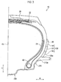
- Fig. 3 is a cross-sectional view showing the pneumatic tire 10 according to the embodiment of the present invention.
- the pneumatic tire 10 has projections 100 for turbulent flow generation extending along the tire radial direction on the tire side portion 30 positioned between a tread 20 grounded on a road surface during running and a bead. It is noted that although the pneumatic tire 10 is filled with air at a predetermined pressure, an inert gas such as nitrogen may also be filled in place of air.
- a projection 100 for turbulent flow generation includes at least a first projection 110 and a second projection 120 separate from the first projection 110. Furthermore, the projection 100 for turbulent flow generation includes a third projection 130 separate from the first projection 110 and the second projection 120.
- the pneumatic tire 10 has a carcass 21 that forms the framework of the pneumatic tire 10, a bead 40 that fits the carcass 21 into a rim flange 210 (described later), and a belt layer 22 arranged outside of the tire radial direction of the carcass 21.
- the carcass 21 is configured by a carcass cord, and a layer made from rubber covering the carcass cord.
- the belt layer 22 is configured such that an organic fiber cord is impregnated with a rubber component. Furthermore, the belt layer 22 is configured by a plurality of layers, and each layer is aligned along a tire radial direction D.
- a bead 40 is arranged along a tire circumferential direction, and is provided on both sides of the tread widthwise direction W via a tire equatorial line CL.
- the second projection 120 is provided at a different position from the first projection 110 in the tire circumferential direction.
- the third projection 130 is provided at the same position as the first projection 110 in the tire circumferential direction. Specifically, the second projection 120 is adjacent to the first projection 110 and the third projection 130 in the tire circumferential direction, and a predetermined gap is formed between the first projection 110 and the second projection 120. Similarly, a predetermined gap is formed between the third projection 130 and the second projection 120.
- a distance d from an upper end 210a of a rim flange 210 of the rim wheel 200 up to the lower end 100a of the projection 100 for turbulent flow generation is 50 mm or more and 250 mm or less.
- the state when the pneumatic tire 10 is assembled in the rim wheel 200 refers to the state when the pneumatic tire 10 is assembled in a standard rim described in ETRTO at an air pressure corresponding to the maximum load described in ETRTO.
- the upper end 210a of the rim flange 210 indicates an end portion outside of the tire radial direction of the rim flange 210.
- the lower end 100a of the projection 100 for turbulent flow generation indicates an end portion inside of the tire radial direction of the turbulent generating projection configuring the projection 100 for turbulent flow generation. That is, in the present embodiment, the lower end 100a of the projection 100 for turbulent flow generation indicates the end portion inside of the tire radial direction of the third projection 130.
- Fig. 4 is a partial exploded perspective view showing the projection 100 for turbulent flow generation of the pneumatic tire 10 according to the embodiment of the present invention
- Fig. 5 is a front view showing the projection 100 for turbulent flow generation of the pneumatic tire 10 according to the embodiment of the present invention.
- the inside end portion 110a which is the end portion inside of the tire radial direction of the first projection 110 overlaps the outside end portion 120b, which is the end portion outside of the tire radial direction of the second projection 120, in the tire radial direction D.
- the outside end portion 130b which is the end portion outside of the tire radial direction of the third projection 130 overlaps the inside end portion 120a, which is the end portion inside of the tire radial direction of the second projection 120, in the tire radial direction D.
- the projection 100 for turbulent flow generation has a width W along the tire circumferential direction, and a length L and height h along the tire radial direction D.
- each of the first projection 110, the second projection 120, and the third projection 130 included in the projection 100 for turbulent flow generation has the width W, length L, and height h. Therefore, the details of the width W, length L, and height h of the projection 100 for turbulent flow generation that are described below are common for the first projection 110, the second projection 120, and the third projection 130.
- the width W along the tire circumferential direction of the projection 100 for turbulent flow generation is 2 mm or more and 10 mm or less.
- the height h of the projection 100 for turbulent flow generation is 3 mm or more and 25 mm or less.
- the length of a region along the tire radial direction D in which the projection 100 for turbulent flow generation is positioned is set to length L1.
- the length L1 indicates the length from the end portion inside of the tire radial direction of the third projection 130 up to the end portion outside of the tire radial direction of the first projection 110.
- the height h of the projection 100 for turbulent flow generation can be set to 10 mm or more and 25 mm or less. Furthermore, more preferably, the height h of the projection 100 for turbulent flow generation is 15 mm or more and 25 mm or less.
- the length L of the projection 100 for turbulent flow generation is calculated by the relational expression between the width W and height h of the projection 100 for turbulent flow generation.
- the length L of the projection 100 for turbulent flow generation is explained in further detail by using the second projection 120 as an example. Note that this point is also common to the first projection 110 and the third projection 130, and therefore, the description concerning the length L of the first projection 110 and the third projection 130 is omitted.
- the length L along the tire radial direction D of the end portion 120c, which is the end portion at the side of the tire side portion 30 of the second projection 120 and is a fixed end is length L2
- the length L along the tire radial direction D of the end portion 120d which is the end portion at the apex side of the second projection 120 and is a free end is length L3.
- the length L3' (corresponding to L3 of the present invention) at the apex side of a turbulent generating projection
- the turbulent generating projection did not swell up even when the oil content adhered to it, and the length remained as length L2'. That is, due to the occurrence of a difference between the length L2' and the length L3", the turbulent generating projection got deformed into a wavy shape.
- the length L3 satisfies the relationship of the Equation 1 although the end portion 120d of the second projection 120 is a free end at the apex side of the second projection 120, no deformation occurs in the end portion 120d of the second projection 120 even when the oil content oozing out from the strut-type shock absorbers that repeat an intense reciprocating motion, and the oil content on the road gets dispersed and adheres to the turbulent generating projection.
- the width G along the tire circumferential direction of the predetermined gap formed between the first projection 110 and the second projection 120 is equal to or less than the width W along the tire circumferential direction of the projection 100 for turbulent flow generation.
- the projection 100 for turbulent flow generation satisfies the relationships of 1.0 ⁇ P/h ⁇ 50.0 and 1.0 ⁇ (P-w)/w ⁇ 100.0.
- P indicates the pitch of projections 100 for turbulent flow generation, which are adjacent in the tire circumferential direction.
- p indicates the distance between the center lines of projections 100 for turbulent flow generation that are adjacent in the tire circumferential direction.
- a slant angle ⁇ a with respect to a radial direction of the projection 100 for turbulent flow generation satisfies the relationship of -30° ⁇ ⁇ a ⁇ 30°.
- the pneumatic tires according to comparative examples 1 to 3 and examples 1 to 6 were used and (3.1.1) heat dissipation effect evaluation was conducted.
- the pneumatic tires according to comparative examples 1 to 3 and examples 1 to 6 used in the comparative evaluation are explained specifically. Data items relating to the pneumatic tire were measured under the following condition:
- Each pneumatic tire differs in the shape and arrangement of the projections for turbulent flow generation, and the other configurations are similar to those of the pneumatic tire 10 of the present embodiment. Hereinafter, the characteristics of each pneumatic tire will be explained.
- the pneumatic tire according to comparative example 1 differs from the pneumatic tire 10 in that it does not have a turbulent generating projection.
- the pneumatic tire according to comparative example 2 has a turbulent generating projection with a vast length in the tire radial direction, and does not have a plurality of projections for turbulent flow generation in the tire radial direction as in the case of the pneumatic tire 10.
- the pneumatic tire according to comparative example 3 has one turbulent generating projection in the tire radial direction such that it satisfies L 2 ⁇ 3.5 ⁇ E ⁇ I as in the pneumatic tire 10.
- the first projection 110 and the second projection 120 of the pneumatic tire 10 are provided alternately along the tire radial direction.
- the Young's modulus E of each of the projections for turbulent flow generation of the pneumatic tire according to examples 1 to 6 is 0.35 kg/mm 2
- the projections for turbulent flow generation satisfy L 2 ⁇ 3.5 ⁇ E ⁇ I of the pneumatic tire 10.
- the length L1 (length of the region in which the projections for turbulent flow generation are positioned along the tire radial direction) of the pneumatic tire according to the examples is 240 mm.
- Pinholes positioned at an interval of 10 mm along the tire radial direction of each pneumatic tire are formed at six locations along the tire circumferential direction. Furthermore, in the tread widthwise direction, a pinhole was formed outside of the tread widthwise direction at approximately 5 mm from the carcass.
- Each pneumatic tire was installed in the front wheel of the vehicle, was made to run on a dry road surface at 15 km/h for 24 hours, the temperature of the pneumatic tire after running was measured with a thermocouple, and the average value was calculated.
- the heat dissipation effect improved as compared to the pneumatic tire according to comparative examples 1 and 3. Furthermore, in the pneumatic tire according to the examples, it was possible to secure the same heat dissipation effect as the pneumatic tire according to comparative example 2.
- the length L of the projection 100 for turbulent flow generation along the tire radial direction D satisfies the Equation 1. That is, the length L becomes the length in which deformation due to bending of the projection 100 for turbulent flow generation does not occur.
- a pneumatic tire 10 that prevents the deformation of the projection 100 for turbulent flow generation due to the oil content dispersed from outside while maintaining the heat dissipation effect of the tire side portion 30 in cases where projections for turbulent flow generation are provided on the tire side portion 30 can be provided.
- the size of the pneumatic tire is extremely large as compared to a general pneumatic tire, the deformation of the projections 100 for turbulent flow generation can be controlled, and the heat dissipation effect of a vast tire side portion 30 can be secured.
- the projection 100 for turbulent flow generation includes at least the first projection 110 and the second projection 120 separate from the first projection 110, and the second projection 120 is provided at a position different from the first projection 110 in the tire circumferential direction. That is, because the projection 100 for turbulent flow generation includes a plurality of projections, the amount of deformation of the projection 100 for turbulent flow generation along the tire radial direction D becomes further less as compared to the conventional turbulent generating projection having a vast length in the tire radial direction D.
- the second projection 120 is provided at a different position from the first projection 110 in the tire circumferential direction, a contact between the second projection 120 and the first projection 110 can be prevented in spite of a deformation in the tire radial direction D, and therefore, the deformation of each projection can be controlled further.
- the end portion inside of the tire radial direction of the first projection 110 overlaps the end portion outside of the tire radial direction of the second projection 120, in the tire radial direction D. Therefore, the flow of the air flowing along the tire side portion 30 is disturbed when the air climbs over the first projection 110 or the second projection 120. When the air whose flow has been disturbed adheres again to the tire side portion 30, the heat dissipation effect of the tire side portion 30 can be achieved.
- the second projection 120 is adjacent to the first projection 110 in the tire circumferential direction, and a predetermined gap (width G) is formed between the first projection 110 and the second projection 120. Therefore, the probability of the air flowing along the tire side portion 30 climbing over the first projection 110 or the second projection 120 becomes higher, That is, by climbing over the first projection 110 or the second projection 120, the heat dissipation effect of the tire side portion 30 can be improved further.
- a predetermined gap (width G) is formed between the first projection 110 and the second projection 120, a contact between the second projection 120 and the first projection 110 can be prevented even when the second projection 120 and the first projection 110 get deformed in the tire radial direction D.
- the pneumatic tire 10 can further improve the heat dissipation effect of the tire side portion 30 while preventing the deformation of the projection 100 for turbulent flow generation.
- the air flowing along the tire side portion 30 has a high probability of climbing over the first projection 110 or the second projection 120. That is, by climbing over the first projection 110 or the second projection 120, the heat dissipation effect of the tire side portion 30 can be improved further.
- the width W of the projection 100 for turbulent flow generation along the tire circumferential direction is 2 mm or more and 10 mm or less, it can further improve the heat dissipation effect of the tire side portion 30 while maintaining the function as a projection that disturbs the flow of the air flowing along the tire side portion 30. It is noted that if the width W is less than 2 mm, the projection 100 for turbulent flow generation might vibrate as a result of the air flowing along the tire side portion 30. Furthermore, if the width W is more than 10 mm, the storage of heat accumulated in the projection 100 for turbulent flow generation is feared to become large.
- the height h of the projection 100 for turbulent flow generation is 3 mm or more and 25 mm or less, when the projection 100 for turbulent flow generation is installed as a tire for a construction vehicle, the heat dissipation effect of the tire side portion 30 can certainly be secured in the practical velocity range of the tire for construction vehicle.
- the distance d from the upper end 210a of the rim flange 210 of the rim wheel 200 up to the lower end 100a of the projection 100 for turbulent flow generation is 50 mm or more and 250 mm or less.
- the projection 100 for turbulent flow generation is feared to get deformed. Furthermore, if an inclination occurs due to a load on the pneumatic tire 10, the projection 100 for turbulent flow generation is feared to get deformed by the rim flange 210. By contrast, when the distance d is 50 mm or more, the deformation of the projection 100 for turbulent flow generation can certainly be prevented. Thus, the occurrence of cracks in the projection 100 for turbulent flow generation as a result of deformation of the projection 100 for turbulent flow generation can also be prevented certainly.
- the projection 100 for turbulent flow generation can sufficiently secure the function as a projection that disturbs the flow of the air flowing along the tire side portion 30.
- the projection 100 for turbulent flow generation can sufficiently secure the function as a projection that disturbs the flow of the air flowing along the tire side portion 30.
- Fig. 6 is a front view showing a projection 100A for turbulent flow generation of a pneumatic tire which is not according to the present invention.
- the projection 100A for turbulent flow generation may be provided such that a slant angle ⁇ is formed with respect to a straight line SL along the tire radial direction D.
- the second projection 120 in the aforementioned embodiment is adjacent to the first projection 110 in the tire circumferential direction, and a predetermined gap including width G is formed between the first projection 110 and the second projection 120.
- a turbulent generating projection as shown in Fig. 7 may also be provided.
- Fig. 7 is a front view showing a projection 100B for turbulent flow generation of a pneumatic tire according to another embodiment of the present invention.
- the projection 100B for turbulent flow generation includes a first projection 110B and a second projection 120B, and a predetermined gap including a width G1 equivalent to the width of the first projection 110B may be formed between the first projection 110B and the second projection 120B.
- the pneumatic tire 10 in the aforementioned embodiment is a tire filled with air or an inert gas, but it is not limited thereto, and for example, it may be a solid tire formed entirely with rubber.
- the shape of the cross section of the projection 100 for turbulent flow generation perpendicularly intersecting in the direction in which the projection 100 for turbulent flow generation in the aforementioned embodiment is extending is rectangular, but it is not limited thereto, and for example, the shape may be triangular.
- the length L of the turbulent generating projection along the tire radial direction D can be set.
- the present invention it is possible to prevent the deformation of the projections for turbulent flow generation due to the oil content dispersed from outside while maintaining the heat dissipation effect of the tire side portion, and therefore, the present invention can be applied to a tire for construction vehicle that runs on an irregular ground and dirty road surface on many occasions.
Claims (10)
- Luftreifen (10), der Turbulenzerzeugungsvorsprünge (100) umfasst, die sich entlang einer Reifenradialrichtung (D), auf einem Reifenseitenabschnitt (30), der zwischen einer Lauffläche (20) und einer Wulst (40) angeordnet ist, erstrecken, wobei
die Turbulenzerzeugungsvorsprünge (100) wenigstens einen ersten Vorsprung (110), einen von dem ersten Vorsprung (110) getrennten zweiten Vorsprung (120) und einen von dem ersten Vorsprung (110) und zweiten Vorsprung (120) getrennten dritten Vorsprung (130) einschließen,
der erste Vorsprung (110) und der dritte Vorsprung (130) an der in einer Reifenumfangsrichtung gleichen Position bereitgestellt werden und getrennt angeordnet sind, wobei sie einen vorbestimmten Spalt haben,
der zweite Vorsprung (120) an einer in der Reifenumfangsrichtung von dem ersten Vorsprung (110) und dem dritten Vorsprung (130) verschiedenen Position bereitgestellt wird und
der Endabschnitt (110a) des ersten Vorsprungs (110) auf der Innenseite in der Reifenradialrichtung (D) den Endabschnitt (120b) des zweiten Vorsprungs (120) auf der Außenseite in der Reifenradialrichtung (D) in der Reifenradialrichtung überlappt und
der Endabschnitt (130b) des dritten Vorsprungs (130) auf der Außenseite in der Reifenradialrichtung (D) den Endabschnitt (120a) des zweiten Vorsprungs (120) auf der Innenseite in der Reifenradialrichtung (D) in der Reifenradialrichtung überlappt, wobei
wenn eine Teilung der benachbarten Turbulenzerzeugungsvorsprünge (100) in der Reifenumfangsrichtung als P definiert ist, eine Höhe der benachbarten Turbulenzerzeugungsvorsprünge (100) als h definiert ist und eine Breite der benachbarten Turbulenzerzeugungsvorsprünge (100) in der Reifenumfangsrichtung als W definiert ist, eine Beziehung von 1,0 ≤ P/h ≤ 50,0 und 1,0 ≤ (P-W)/W≤ 100,0 erfüllt ist. - Luftreifen (10) nach Anspruch 1, wobei
der zweite Vorsprung (120) dem ersten Vorsprung (110) in der Reifenumfangsrichtung benachbart ist,
ein vorbestimmter Spalt (G) zwischen dem ersten Vorsprung (110) und dem zweite Vorsprung (120) geformt ist. - Luftreifen (10) nach Anspruch 2, wobei
der zweite Vorsprung (120) dem dritten Vorsprung (130) in der Reifenumfangsrichtung benachbart ist, und
ein vorbestimmter Spalt zwischen dem dritten Vorsprung (130) und dem zweite Vorsprung (120) geformt ist. - Luftreifen (10) nach Anspruch 3, wobei der vorbestimmte Spalt (G) gleich einer Breite (W) des Turbulenzerzeugungsvorsprungs (100) entlang der Reifenumfangsrichtung oder geringer als dieselbe ist.
- Luftreifen (10) nach einem der Ansprüche 1 bis 4, wobei eine Breite des Turbulenzerzeugungsvorsprungs (100) entlang der Reifenumfangsrichtung 2 mm oder mehr und 10 mm oder weniger beträgt.
- Luftreifen (10) nach einem der Ansprüche 1 bis 5, wobei eine Höhe (h) des Turbulenzerzeugungsvorsprungs (100) 3 mm oder mehr und 25 mm oder weniger beträgt.
- Luftreifen (10) nach einem der Ansprüche 1 bis 6, wobei in einem Zustand, in dem der Luftreifen in einem Felgenrad (200) montiert ist, ein Abstand von einem oberen Ende (210a) eines Felgenflanschs des Felgenrades hinauf zu einem unteren Ende (100a) des Turbulenzerzeugungsvorsprungs (100) 50 mm und mehr und 250 mm und weniger beträgt.
- Luftreifen (10) nach Anspruch 6, wobei die Höhe des Turbulenzerzeugungsvorsprungs (100) 10 mm oder mehr und 25 mm oder weniger beträgt.
- Luftreifen (10) nach einem der Ansprüche 1 bis 7, wobei, wenn L eine Länge des Turbulenzerzeugungsvorsprungs (100) entlang der Reifenradialrichtung (D) bezeichnet, E einen Elastizitätsmodul von Formmaterial, das den Turbulenzerzeugungsvorsprung (100) bildet, bezeichnet und I ein Flächenträgheitsmoment eines Querschnitts des Turbulenzerzeugungsvorsprungs (100), der senkrecht in der Richtung schneidet, in der sich der Turbulenzerzeugungsvorsprung (100) erstreckt, bezeichnet,
der Turbulenzerzeugungsvorsprung (100) die Beziehung von L2 ≤ 3,5 × E × I erfüllt. - Luftreifen (10) nach einem der Ansprüche 1 bis 9, wobei der Luftreifen (10) ein Reifen für schwere Lasten ist.
Applications Claiming Priority (2)
| Application Number | Priority Date | Filing Date | Title |
|---|---|---|---|
| JP2009109150 | 2009-04-28 | ||
| EP10769789.8A EP2425992B1 (de) | 2009-04-28 | 2010-04-28 | Luftreifen |
Related Parent Applications (2)
| Application Number | Title | Priority Date | Filing Date |
|---|---|---|---|
| EP10769789.8A Division EP2425992B1 (de) | 2009-04-28 | 2010-04-28 | Luftreifen |
| EP10769789.8A Division-Into EP2425992B1 (de) | 2009-04-28 | 2010-04-28 | Luftreifen |
Publications (2)
| Publication Number | Publication Date |
|---|---|
| EP2711203A1 EP2711203A1 (de) | 2014-03-26 |
| EP2711203B1 true EP2711203B1 (de) | 2015-12-09 |
Family
ID=43032235
Family Applications (2)
| Application Number | Title | Priority Date | Filing Date |
|---|---|---|---|
| EP10769789.8A Not-in-force EP2425992B1 (de) | 2009-04-28 | 2010-04-28 | Luftreifen |
| EP13197717.5A Not-in-force EP2711203B1 (de) | 2009-04-28 | 2010-04-28 | Luftreifen |
Family Applications Before (1)
| Application Number | Title | Priority Date | Filing Date |
|---|---|---|---|
| EP10769789.8A Not-in-force EP2425992B1 (de) | 2009-04-28 | 2010-04-28 | Luftreifen |
Country Status (8)
| Country | Link |
|---|---|
| US (2) | US20120097305A1 (de) |
| EP (2) | EP2425992B1 (de) |
| JP (2) | JP5451753B2 (de) |
| CN (2) | CN103419572B (de) |
| BR (1) | BRPI1014613A8 (de) |
| ES (2) | ES2561101T3 (de) |
| RU (2) | RU2499682C2 (de) |
| WO (1) | WO2010126091A1 (de) |
Families Citing this family (12)
| Publication number | Priority date | Publication date | Assignee | Title |
|---|---|---|---|---|
| JP5781852B2 (ja) * | 2011-07-13 | 2015-09-24 | 株式会社ブリヂストン | タイヤ |
| JP5695543B2 (ja) * | 2011-10-31 | 2015-04-08 | 住友ゴム工業株式会社 | 空気入りタイヤ |
| CN104428147A (zh) * | 2012-07-11 | 2015-03-18 | 横滨橡胶株式会社 | 充气轮胎 |
| JP5246370B1 (ja) * | 2012-08-20 | 2013-07-24 | 横浜ゴム株式会社 | 空気入りタイヤ |
| JP5956942B2 (ja) | 2013-02-22 | 2016-07-27 | 株式会社ブリヂストン | タイヤ |
| JP2015034004A (ja) * | 2013-08-08 | 2015-02-19 | クムホ タイヤ カンパニー インコーポレーテッド | 冷却ピンのピッチ決定方法およびこれを用いた空気入りタイヤ |
| JP6257438B2 (ja) * | 2014-05-08 | 2018-01-10 | 東洋ゴム工業株式会社 | 空気入りタイヤ |
| JP6349199B2 (ja) * | 2014-08-08 | 2018-06-27 | 株式会社ブリヂストン | 空気入りタイヤ |
| JP6699192B2 (ja) * | 2016-01-21 | 2020-05-27 | 住友ゴム工業株式会社 | 空気入りタイヤ |
| JP6720044B2 (ja) * | 2016-10-06 | 2020-07-08 | 株式会社ブリヂストン | タイヤ |
| FR3060458A1 (fr) * | 2016-12-20 | 2018-06-22 | Compagnie Generale Des Etablissements Michelin | Pneumatique aux flancs renforces resistant aux attaques chimiques |
| JP6969279B2 (ja) * | 2017-10-24 | 2021-11-24 | 住友ゴム工業株式会社 | タイヤ |
Family Cites Families (18)
| Publication number | Priority date | Publication date | Assignee | Title |
|---|---|---|---|---|
| GB178496A (en) * | 1920-12-16 | 1922-04-18 | Wood Milne Ltd | Improvements in pneumatic tyre covers for motor and other vehicles |
| JPS5424762B2 (de) * | 1974-09-18 | 1979-08-23 | ||
| US4328850A (en) * | 1978-08-07 | 1982-05-11 | The Toyo Rubber Industry Co., Ltd. | Radial tire for truck and bus having specified tread to tire width ratio |
| JPS62155108A (ja) * | 1985-12-27 | 1987-07-10 | Bridgestone Corp | 空気入りラジアルタイヤ |
| US5253690A (en) * | 1989-12-28 | 1993-10-19 | Sumitomo Rubber Industries, Ltd. | High speed heavy duty tire including bead part with side packing rubber |
| JPH11321243A (ja) * | 1998-05-18 | 1999-11-24 | Bridgestone Corp | 多数の半球状の突起よりなる環状装飾体を備えた空気入りタイヤ |
| EP1201414B2 (de) * | 2000-10-30 | 2019-12-04 | Sumitomo Rubber Industries, Ltd. | Verfahren zum Herstellen der Seitenwände von Fahrzeugreifen |
| JP4234468B2 (ja) * | 2003-03-11 | 2009-03-04 | 横浜ゴム株式会社 | 空気入りタイヤ |
| JP4510545B2 (ja) * | 2004-08-04 | 2010-07-28 | 東洋ゴム工業株式会社 | 回転補助翼付きの車両用タイヤ |
| JP4818272B2 (ja) * | 2005-09-13 | 2011-11-16 | 株式会社ブリヂストン | ランフラットタイヤ |
| WO2008096879A1 (ja) * | 2007-02-09 | 2008-08-14 | Bridgestone Corporation | 空気入りタイヤ |
| JP5081477B2 (ja) * | 2007-03-12 | 2012-11-28 | 株式会社ブリヂストン | 空気入りタイヤ |
| JP5081476B2 (ja) * | 2007-03-12 | 2012-11-28 | 株式会社ブリヂストン | 空気入りタイヤ |
| EP2141031B1 (de) * | 2007-03-12 | 2016-03-09 | Bridgestone Corporation | Luftreifen |
| WO2009029088A1 (en) * | 2007-08-24 | 2009-03-05 | Societe De Technologie Michelin | Tire having sidewall protection |
| JP5109595B2 (ja) | 2007-10-31 | 2012-12-26 | ダイキン工業株式会社 | 調湿装置 |
| JP5222551B2 (ja) * | 2007-12-28 | 2013-06-26 | 株式会社ブリヂストン | 空気入りタイヤ |
| CN101909907B (zh) * | 2007-12-28 | 2014-03-12 | 株式会社普利司通 | 充气轮胎 |
-
2010
- 2010-04-28 CN CN201310367333.3A patent/CN103419572B/zh not_active Expired - Fee Related
- 2010-04-28 JP JP2011511442A patent/JP5451753B2/ja not_active Expired - Fee Related
- 2010-04-28 WO PCT/JP2010/057595 patent/WO2010126091A1/ja active Application Filing
- 2010-04-28 CN CN201080026786.4A patent/CN102458885B/zh not_active Expired - Fee Related
- 2010-04-28 BR BRPI1014613A patent/BRPI1014613A8/pt active Search and Examination
- 2010-04-28 EP EP10769789.8A patent/EP2425992B1/de not_active Not-in-force
- 2010-04-28 EP EP13197717.5A patent/EP2711203B1/de not_active Not-in-force
- 2010-04-28 ES ES13197717.5T patent/ES2561101T3/es active Active
- 2010-04-28 ES ES10769789.8T patent/ES2562638T3/es active Active
- 2010-04-28 US US13/266,704 patent/US20120097305A1/en not_active Abandoned
- 2010-04-28 RU RU2011148145/11A patent/RU2499682C2/ru active
- 2010-04-28 RU RU2013138225A patent/RU2630878C2/ru active
-
2013
- 2013-07-08 US US13/936,700 patent/US20130292025A1/en not_active Abandoned
- 2013-09-12 JP JP2013189301A patent/JP5837907B2/ja not_active Expired - Fee Related
Also Published As
| Publication number | Publication date |
|---|---|
| BRPI1014613A2 (pt) | 2018-06-19 |
| CN102458885A (zh) | 2012-05-16 |
| RU2011148145A (ru) | 2013-06-10 |
| US20120097305A1 (en) | 2012-04-26 |
| JP2013241184A (ja) | 2013-12-05 |
| RU2630878C2 (ru) | 2017-09-13 |
| CN102458885B (zh) | 2016-01-06 |
| BRPI1014613A8 (pt) | 2019-10-22 |
| JP5837907B2 (ja) | 2015-12-24 |
| CN103419572A (zh) | 2013-12-04 |
| RU2013138225A (ru) | 2015-02-20 |
| EP2711203A1 (de) | 2014-03-26 |
| CN103419572B (zh) | 2016-01-06 |
| JP5451753B2 (ja) | 2014-03-26 |
| WO2010126091A1 (ja) | 2010-11-04 |
| EP2425992A1 (de) | 2012-03-07 |
| US20130292025A1 (en) | 2013-11-07 |
| RU2499682C2 (ru) | 2013-11-27 |
| JPWO2010126091A1 (ja) | 2012-11-01 |
| EP2425992B1 (de) | 2015-11-25 |
| ES2561101T3 (es) | 2016-02-24 |
| ES2562638T3 (es) | 2016-03-07 |
| EP2425992A4 (de) | 2013-04-03 |
Similar Documents
| Publication | Publication Date | Title |
|---|---|---|
| EP2711203B1 (de) | Luftreifen | |
| RU2436685C2 (ru) | Пневматическая шина | |
| WO2009084633A1 (ja) | 空気入りタイヤ | |
| KR101677304B1 (ko) | 공기 타이어 | |
| US10226969B2 (en) | Heavy load tire with curved sidewall recess | |
| EP2783882B1 (de) | Reifen | |
| EP2610079B1 (de) | Reifen | |
| EP2881266B1 (de) | Luftreifen | |
| EP3501858B1 (de) | Luftreifen sowie luftreifen und felgenanordnung | |
| US20120211135A1 (en) | Tire | |
| AU2016336312B2 (en) | Pneumatic tire | |
| JP2009160991A (ja) | 空気入りタイヤ | |
| US20200009921A1 (en) | Tire | |
| AU2016334764A1 (en) | Pneumatic tire | |
| JP3075487B2 (ja) | 建設車両用ラジアルタイヤ | |
| JP2007118903A (ja) | 空気入りタイヤ | |
| JP6660251B2 (ja) | ランフラットラジアルタイヤ | |
| JP2000177314A (ja) | 重荷重用空気入りラジアルタイヤ | |
| JPH08290706A (ja) | 重荷重用空気入りタイヤ | |
| JP2022006591A (ja) | タイヤ | |
| JP6911560B2 (ja) | 空気入りタイヤ | |
| JP4316324B2 (ja) | 空気入りタイヤ | |
| CN112292272A (zh) | 工程车辆用轮胎 | |
| JPH089282B2 (ja) | 重荷重用ラジアルタイヤ | |
| JPH06227210A (ja) | 重荷重用空気入りラジアルタイヤ |
Legal Events
| Date | Code | Title | Description |
|---|---|---|---|
| PUAI | Public reference made under article 153(3) epc to a published international application that has entered the european phase |
Free format text: ORIGINAL CODE: 0009012 |
|
| 17P | Request for examination filed |
Effective date: 20131217 |
|
| AC | Divisional application: reference to earlier application |
Ref document number: 2425992 Country of ref document: EP Kind code of ref document: P |
|
| AK | Designated contracting states |
Kind code of ref document: A1 Designated state(s): AT BE BG CH CY CZ DE DK EE ES FI FR GB GR HR HU IE IS IT LI LT LU LV MC MK MT NL NO PL PT RO SE SI SK SM TR |
|
| GRAP | Despatch of communication of intention to grant a patent |
Free format text: ORIGINAL CODE: EPIDOSNIGR1 |
|
| INTG | Intention to grant announced |
Effective date: 20150608 |
|
| GRAS | Grant fee paid |
Free format text: ORIGINAL CODE: EPIDOSNIGR3 |
|
| GRAA | (expected) grant |
Free format text: ORIGINAL CODE: 0009210 |
|
| AC | Divisional application: reference to earlier application |
Ref document number: 2425992 Country of ref document: EP Kind code of ref document: P |
|
| AK | Designated contracting states |
Kind code of ref document: B1 Designated state(s): AT BE BG CH CY CZ DE DK EE ES FI FR GB GR HR HU IE IS IT LI LT LU LV MC MK MT NL NO PL PT RO SE SI SK SM TR |
|
| REG | Reference to a national code |
Ref country code: GB Ref legal event code: FG4D |
|
| REG | Reference to a national code |
Ref country code: AT Ref legal event code: REF Ref document number: 764397 Country of ref document: AT Kind code of ref document: T Effective date: 20151215 Ref country code: CH Ref legal event code: EP |
|
| REG | Reference to a national code |
Ref country code: IE Ref legal event code: FG4D |
|
| REG | Reference to a national code |
Ref country code: DE Ref legal event code: R096 Ref document number: 602010029446 Country of ref document: DE |
|
| REG | Reference to a national code |
Ref country code: ES Ref legal event code: FG2A Ref document number: 2561101 Country of ref document: ES Kind code of ref document: T3 Effective date: 20160224 |
|
| REG | Reference to a national code |
Ref country code: LT Ref legal event code: MG4D |
|
| REG | Reference to a national code |
Ref country code: NL Ref legal event code: MP Effective date: 20151209 |
|
| REG | Reference to a national code |
Ref country code: FR Ref legal event code: PLFP Year of fee payment: 7 |
|
| PG25 | Lapsed in a contracting state [announced via postgrant information from national office to epo] |
Ref country code: LT Free format text: LAPSE BECAUSE OF FAILURE TO SUBMIT A TRANSLATION OF THE DESCRIPTION OR TO PAY THE FEE WITHIN THE PRESCRIBED TIME-LIMIT Effective date: 20151209 Ref country code: NO Free format text: LAPSE BECAUSE OF FAILURE TO SUBMIT A TRANSLATION OF THE DESCRIPTION OR TO PAY THE FEE WITHIN THE PRESCRIBED TIME-LIMIT Effective date: 20160309 |
|
| REG | Reference to a national code |
Ref country code: AT Ref legal event code: MK05 Ref document number: 764397 Country of ref document: AT Kind code of ref document: T Effective date: 20151209 |
|
| PG25 | Lapsed in a contracting state [announced via postgrant information from national office to epo] |
Ref country code: SE Free format text: LAPSE BECAUSE OF FAILURE TO SUBMIT A TRANSLATION OF THE DESCRIPTION OR TO PAY THE FEE WITHIN THE PRESCRIBED TIME-LIMIT Effective date: 20151209 Ref country code: LV Free format text: LAPSE BECAUSE OF FAILURE TO SUBMIT A TRANSLATION OF THE DESCRIPTION OR TO PAY THE FEE WITHIN THE PRESCRIBED TIME-LIMIT Effective date: 20151209 Ref country code: NL Free format text: LAPSE BECAUSE OF FAILURE TO SUBMIT A TRANSLATION OF THE DESCRIPTION OR TO PAY THE FEE WITHIN THE PRESCRIBED TIME-LIMIT Effective date: 20151209 Ref country code: GR Free format text: LAPSE BECAUSE OF FAILURE TO SUBMIT A TRANSLATION OF THE DESCRIPTION OR TO PAY THE FEE WITHIN THE PRESCRIBED TIME-LIMIT Effective date: 20160310 Ref country code: FI Free format text: LAPSE BECAUSE OF FAILURE TO SUBMIT A TRANSLATION OF THE DESCRIPTION OR TO PAY THE FEE WITHIN THE PRESCRIBED TIME-LIMIT Effective date: 20151209 |
|
| PG25 | Lapsed in a contracting state [announced via postgrant information from national office to epo] |
Ref country code: IS Free format text: LAPSE BECAUSE OF FAILURE TO SUBMIT A TRANSLATION OF THE DESCRIPTION OR TO PAY THE FEE WITHIN THE PRESCRIBED TIME-LIMIT Effective date: 20151209 |
|
| PG25 | Lapsed in a contracting state [announced via postgrant information from national office to epo] |
Ref country code: IT Free format text: LAPSE BECAUSE OF FAILURE TO SUBMIT A TRANSLATION OF THE DESCRIPTION OR TO PAY THE FEE WITHIN THE PRESCRIBED TIME-LIMIT Effective date: 20151209 Ref country code: CZ Free format text: LAPSE BECAUSE OF FAILURE TO SUBMIT A TRANSLATION OF THE DESCRIPTION OR TO PAY THE FEE WITHIN THE PRESCRIBED TIME-LIMIT Effective date: 20151209 |
|
| PG25 | Lapsed in a contracting state [announced via postgrant information from national office to epo] |
Ref country code: PT Free format text: LAPSE BECAUSE OF FAILURE TO SUBMIT A TRANSLATION OF THE DESCRIPTION OR TO PAY THE FEE WITHIN THE PRESCRIBED TIME-LIMIT Effective date: 20160411 Ref country code: IS Free format text: LAPSE BECAUSE OF FAILURE TO SUBMIT A TRANSLATION OF THE DESCRIPTION OR TO PAY THE FEE WITHIN THE PRESCRIBED TIME-LIMIT Effective date: 20160409 Ref country code: BE Free format text: LAPSE BECAUSE OF NON-PAYMENT OF DUE FEES Effective date: 20160430 Ref country code: RO Free format text: LAPSE BECAUSE OF FAILURE TO SUBMIT A TRANSLATION OF THE DESCRIPTION OR TO PAY THE FEE WITHIN THE PRESCRIBED TIME-LIMIT Effective date: 20151209 Ref country code: SM Free format text: LAPSE BECAUSE OF FAILURE TO SUBMIT A TRANSLATION OF THE DESCRIPTION OR TO PAY THE FEE WITHIN THE PRESCRIBED TIME-LIMIT Effective date: 20151209 Ref country code: AT Free format text: LAPSE BECAUSE OF FAILURE TO SUBMIT A TRANSLATION OF THE DESCRIPTION OR TO PAY THE FEE WITHIN THE PRESCRIBED TIME-LIMIT Effective date: 20151209 Ref country code: SK Free format text: LAPSE BECAUSE OF FAILURE TO SUBMIT A TRANSLATION OF THE DESCRIPTION OR TO PAY THE FEE WITHIN THE PRESCRIBED TIME-LIMIT Effective date: 20151209 Ref country code: EE Free format text: LAPSE BECAUSE OF FAILURE TO SUBMIT A TRANSLATION OF THE DESCRIPTION OR TO PAY THE FEE WITHIN THE PRESCRIBED TIME-LIMIT Effective date: 20151209 |
|
| REG | Reference to a national code |
Ref country code: DE Ref legal event code: R097 Ref document number: 602010029446 Country of ref document: DE |
|
| PLBE | No opposition filed within time limit |
Free format text: ORIGINAL CODE: 0009261 |
|
| STAA | Information on the status of an ep patent application or granted ep patent |
Free format text: STATUS: NO OPPOSITION FILED WITHIN TIME LIMIT |
|
| PG25 | Lapsed in a contracting state [announced via postgrant information from national office to epo] |
Ref country code: DK Free format text: LAPSE BECAUSE OF FAILURE TO SUBMIT A TRANSLATION OF THE DESCRIPTION OR TO PAY THE FEE WITHIN THE PRESCRIBED TIME-LIMIT Effective date: 20151209 Ref country code: PL Free format text: LAPSE BECAUSE OF FAILURE TO SUBMIT A TRANSLATION OF THE DESCRIPTION OR TO PAY THE FEE WITHIN THE PRESCRIBED TIME-LIMIT Effective date: 20151209 |
|
| REG | Reference to a national code |
Ref country code: DE Ref legal event code: R119 Ref document number: 602010029446 Country of ref document: DE |
|
| 26N | No opposition filed |
Effective date: 20160912 |
|
| PG25 | Lapsed in a contracting state [announced via postgrant information from national office to epo] |
Ref country code: SI Free format text: LAPSE BECAUSE OF FAILURE TO SUBMIT A TRANSLATION OF THE DESCRIPTION OR TO PAY THE FEE WITHIN THE PRESCRIBED TIME-LIMIT Effective date: 20151209 |
|
| REG | Reference to a national code |
Ref country code: CH Ref legal event code: PL |
|
| GBPC | Gb: european patent ceased through non-payment of renewal fee |
Effective date: 20160428 |
|
| PG25 | Lapsed in a contracting state [announced via postgrant information from national office to epo] |
Ref country code: BE Free format text: LAPSE BECAUSE OF FAILURE TO SUBMIT A TRANSLATION OF THE DESCRIPTION OR TO PAY THE FEE WITHIN THE PRESCRIBED TIME-LIMIT Effective date: 20151209 |
|
| REG | Reference to a national code |
Ref country code: IE Ref legal event code: MM4A |
|
| PG25 | Lapsed in a contracting state [announced via postgrant information from national office to epo] |
Ref country code: GB Free format text: LAPSE BECAUSE OF NON-PAYMENT OF DUE FEES Effective date: 20160428 Ref country code: LI Free format text: LAPSE BECAUSE OF NON-PAYMENT OF DUE FEES Effective date: 20160430 Ref country code: CH Free format text: LAPSE BECAUSE OF NON-PAYMENT OF DUE FEES Effective date: 20160430 Ref country code: DE Free format text: LAPSE BECAUSE OF NON-PAYMENT OF DUE FEES Effective date: 20161101 |
|
| REG | Reference to a national code |
Ref country code: FR Ref legal event code: PLFP Year of fee payment: 8 |
|
| PG25 | Lapsed in a contracting state [announced via postgrant information from national office to epo] |
Ref country code: IE Free format text: LAPSE BECAUSE OF NON-PAYMENT OF DUE FEES Effective date: 20160428 |
|
| REG | Reference to a national code |
Ref country code: FR Ref legal event code: PLFP Year of fee payment: 9 |
|
| PG25 | Lapsed in a contracting state [announced via postgrant information from national office to epo] |
Ref country code: CY Free format text: LAPSE BECAUSE OF FAILURE TO SUBMIT A TRANSLATION OF THE DESCRIPTION OR TO PAY THE FEE WITHIN THE PRESCRIBED TIME-LIMIT Effective date: 20151209 Ref country code: HU Free format text: LAPSE BECAUSE OF FAILURE TO SUBMIT A TRANSLATION OF THE DESCRIPTION OR TO PAY THE FEE WITHIN THE PRESCRIBED TIME-LIMIT; INVALID AB INITIO Effective date: 20100428 |
|
| PG25 | Lapsed in a contracting state [announced via postgrant information from national office to epo] |
Ref country code: MT Free format text: LAPSE BECAUSE OF NON-PAYMENT OF DUE FEES Effective date: 20160430 Ref country code: MK Free format text: LAPSE BECAUSE OF FAILURE TO SUBMIT A TRANSLATION OF THE DESCRIPTION OR TO PAY THE FEE WITHIN THE PRESCRIBED TIME-LIMIT Effective date: 20151209 Ref country code: MC Free format text: LAPSE BECAUSE OF FAILURE TO SUBMIT A TRANSLATION OF THE DESCRIPTION OR TO PAY THE FEE WITHIN THE PRESCRIBED TIME-LIMIT Effective date: 20151209 Ref country code: HR Free format text: LAPSE BECAUSE OF FAILURE TO SUBMIT A TRANSLATION OF THE DESCRIPTION OR TO PAY THE FEE WITHIN THE PRESCRIBED TIME-LIMIT Effective date: 20151209 Ref country code: TR Free format text: LAPSE BECAUSE OF FAILURE TO SUBMIT A TRANSLATION OF THE DESCRIPTION OR TO PAY THE FEE WITHIN THE PRESCRIBED TIME-LIMIT Effective date: 20151209 |
|
| PG25 | Lapsed in a contracting state [announced via postgrant information from national office to epo] |
Ref country code: BG Free format text: LAPSE BECAUSE OF FAILURE TO SUBMIT A TRANSLATION OF THE DESCRIPTION OR TO PAY THE FEE WITHIN THE PRESCRIBED TIME-LIMIT Effective date: 20151209 |
|
| PGFP | Annual fee paid to national office [announced via postgrant information from national office to epo] |
Ref country code: LU Payment date: 20200420 Year of fee payment: 11 Ref country code: ES Payment date: 20200629 Year of fee payment: 11 Ref country code: FR Payment date: 20200420 Year of fee payment: 11 |
|
| PG25 | Lapsed in a contracting state [announced via postgrant information from national office to epo] |
Ref country code: LU Free format text: LAPSE BECAUSE OF NON-PAYMENT OF DUE FEES Effective date: 20210428 |
|
| PG25 | Lapsed in a contracting state [announced via postgrant information from national office to epo] |
Ref country code: FR Free format text: LAPSE BECAUSE OF NON-PAYMENT OF DUE FEES Effective date: 20210430 |
|
| REG | Reference to a national code |
Ref country code: ES Ref legal event code: FD2A Effective date: 20220727 |
|
| PG25 | Lapsed in a contracting state [announced via postgrant information from national office to epo] |
Ref country code: ES Free format text: LAPSE BECAUSE OF NON-PAYMENT OF DUE FEES Effective date: 20210429 |