EP2711132B1 - Messvorrichtung - Google Patents
Messvorrichtung Download PDFInfo
- Publication number
- EP2711132B1 EP2711132B1 EP13004469.6A EP13004469A EP2711132B1 EP 2711132 B1 EP2711132 B1 EP 2711132B1 EP 13004469 A EP13004469 A EP 13004469A EP 2711132 B1 EP2711132 B1 EP 2711132B1
- Authority
- EP
- European Patent Office
- Prior art keywords
- measuring
- calibration
- measuring device
- angle
- axis
- Prior art date
- Legal status (The legal status is an assumption and is not a legal conclusion. Google has not performed a legal analysis and makes no representation as to the accuracy of the status listed.)
- Revoked
Links
Images


Classifications
-
- B—PERFORMING OPERATIONS; TRANSPORTING
- B24—GRINDING; POLISHING
- B24B—MACHINES, DEVICES, OR PROCESSES FOR GRINDING OR POLISHING; DRESSING OR CONDITIONING OF ABRADING SURFACES; FEEDING OF GRINDING, POLISHING, OR LAPPING AGENTS
- B24B49/00—Measuring or gauging equipment for controlling the feed movement of the grinding tool or work; Arrangements of indicating or measuring equipment, e.g. for indicating the start of the grinding operation
- B24B49/02—Measuring or gauging equipment for controlling the feed movement of the grinding tool or work; Arrangements of indicating or measuring equipment, e.g. for indicating the start of the grinding operation according to the instantaneous size and required size of the workpiece acted upon, the measuring or gauging being continuous or intermittent
- B24B49/04—Measuring or gauging equipment for controlling the feed movement of the grinding tool or work; Arrangements of indicating or measuring equipment, e.g. for indicating the start of the grinding operation according to the instantaneous size and required size of the workpiece acted upon, the measuring or gauging being continuous or intermittent involving measurement of the workpiece at the place of grinding during grinding operation
-
- G—PHYSICS
- G01—MEASURING; TESTING
- G01B—MEASURING LENGTH, THICKNESS OR SIMILAR LINEAR DIMENSIONS; MEASURING ANGLES; MEASURING AREAS; MEASURING IRREGULARITIES OF SURFACES OR CONTOURS
- G01B5/00—Measuring arrangements characterised by the use of mechanical techniques
- G01B5/08—Measuring arrangements characterised by the use of mechanical techniques for measuring diameters
- G01B5/10—Measuring arrangements characterised by the use of mechanical techniques for measuring diameters of objects while moving
-
- B—PERFORMING OPERATIONS; TRANSPORTING
- B24—GRINDING; POLISHING
- B24B—MACHINES, DEVICES, OR PROCESSES FOR GRINDING OR POLISHING; DRESSING OR CONDITIONING OF ABRADING SURFACES; FEEDING OF GRINDING, POLISHING, OR LAPPING AGENTS
- B24B49/00—Measuring or gauging equipment for controlling the feed movement of the grinding tool or work; Arrangements of indicating or measuring equipment, e.g. for indicating the start of the grinding operation
- B24B49/02—Measuring or gauging equipment for controlling the feed movement of the grinding tool or work; Arrangements of indicating or measuring equipment, e.g. for indicating the start of the grinding operation according to the instantaneous size and required size of the workpiece acted upon, the measuring or gauging being continuous or intermittent
- B24B49/04—Measuring or gauging equipment for controlling the feed movement of the grinding tool or work; Arrangements of indicating or measuring equipment, e.g. for indicating the start of the grinding operation according to the instantaneous size and required size of the workpiece acted upon, the measuring or gauging being continuous or intermittent involving measurement of the workpiece at the place of grinding during grinding operation
- B24B49/045—Specially adapted gauging instruments
-
- B—PERFORMING OPERATIONS; TRANSPORTING
- B24—GRINDING; POLISHING
- B24B—MACHINES, DEVICES, OR PROCESSES FOR GRINDING OR POLISHING; DRESSING OR CONDITIONING OF ABRADING SURFACES; FEEDING OF GRINDING, POLISHING, OR LAPPING AGENTS
- B24B5/00—Machines or devices designed for grinding surfaces of revolution on work, including those which also grind adjacent plane surfaces; Accessories therefor
- B24B5/36—Single-purpose machines or devices
- B24B5/42—Single-purpose machines or devices for grinding crankshafts or crankpins
-
- G—PHYSICS
- G01—MEASURING; TESTING
- G01B—MEASURING LENGTH, THICKNESS OR SIMILAR LINEAR DIMENSIONS; MEASURING ANGLES; MEASURING AREAS; MEASURING IRREGULARITIES OF SURFACES OR CONTOURS
- G01B5/00—Measuring arrangements characterised by the use of mechanical techniques
- G01B5/08—Measuring arrangements characterised by the use of mechanical techniques for measuring diameters
-
- G—PHYSICS
- G01—MEASURING; TESTING
- G01B—MEASURING LENGTH, THICKNESS OR SIMILAR LINEAR DIMENSIONS; MEASURING ANGLES; MEASURING AREAS; MEASURING IRREGULARITIES OF SURFACES OR CONTOURS
- G01B5/00—Measuring arrangements characterised by the use of mechanical techniques
- G01B5/20—Measuring arrangements characterised by the use of mechanical techniques for measuring contours or curvatures
- G01B5/201—Measuring arrangements characterised by the use of mechanical techniques for measuring contours or curvatures for measuring roundness
Definitions
- the invention relates to a measuring device referred to in the preamble of claim 1 for in-process measurement of test specimens during a machining operation on a processing machine, in particular a grinding machine.
- crankshafts In the manufacture of crankshafts, it is necessary to grind the crankpins of the crankshaft to size on a grinding machine. In order to ensure that the grinding process is terminated as soon as a desired level is reached, it is necessary to continuously check the crank pin during the machining process, in particular with regard to its diameter and its roundness, during an in-process measuring process.
- EP-A-0859689 discloses a corresponding measuring device. A similar measuring device is also through DE 4412682 A1 known.
- a measuring device which is used for in-process measurement of crankpins during a grinding operation on a grinding machine.
- the known measuring device has a measuring head, which is connected via a linkage about a first pivot axis pivotally connected to a base body of the measuring device.
- the known measuring device further comprises means for pivoting in and out of the measuring head in a measuring position or from the measuring position. to Performing an in-process measurement on a crank pin, the measuring head is pivoted by the means provided for this purpose into a measuring position in which the measuring head, for example by means of a measuring prism, comes to rest on the crank pin to be measured.
- the crank pin performs an orbital rotation about the axis of rotation of the crankshaft.
- the grinding wheel remains in contact with the crank pin and is mounted for this purpose to be movable radially to the axis of rotation of the crankshaft.
- the measuring head retraces the movements of the crankpin.
- the main body of the measuring device is connected to a base body of the grinding machine, so that the measuring device is moved synchronously with the grinding wheel of the grinding machine during the grinding process in the radial direction of the crankshaft. Similar measuring devices are also through DE 10 2009 042 252 A1 and DE 2010 013 069 A1 known.
- DE 10205512 A1 is a measuring device for machines for machining workpieces, in particular of crankshafts or camshafts known.
- EP-A-0322120 For example, a device and a method for non-contact measurement of cylindrical workpieces are known.
- a measuring device for in-process measurement on test specimens during a machining operation on a processing machine which has a main body and a measuring head, the is movable between a rest position and a measurement position and is connected to the main body via a linkage, which is designed and arranged such that the measuring head in the measuring position orbital rotation of the specimen follows about an axis of rotation, wherein the measuring head deflectable along a linear axis probe for recording of measured values during a measuring process.
- the measuring device known from the document further comprises a control device for controlling the measuring process, wherein the measuring device is provided for diameter and Lundesmus waist of crankpins of a crankshaft during a machining operation on a grinding machine.
- a measuring device of the type in question for in-process measurement on test specimens during a machining operation on a processing machine comprising a main body and a measuring head, which between a rest position and a measuring position is movable and connected to the main body via a linkage, which is designed and arranged such that the measuring head in the measuring position orbital rotation of the specimen follows about an axis of rotation.
- the measuring head has a measuring probe deflectable along a linear axis for recording measured values during the measuring process and a control device for controlling the measuring process, wherein the measuring device can be calibrated in a calibration mode.
- the invention has for its object to provide a measuring device referred to in the preamble of claim 1, which is improved in terms of measurement accuracy and reliability.
- the known measuring device measured values are recorded relative to the measuring head during a relative rotation of the test object, for example a crank pin, by means of which the component contour is mathematically reconstructed.
- the reconstruction can be carried out by means of an iteration method, as can be seen from the DE 2009 032 353 A1 is known. However, the reconstruction can also be done on the basis of a Fourier analysis, as can be seen from the EP 1 263 547 B1 is known.
- the geometric conditions of the measuring device for example and in particular with regard to the shape of a measuring prism of the measuring head and the arrangement of the measuring head relative to the test object, enter into the reconstruction.
- the geometric conditions of the measuring device with the accuracy of the component tolerances used are considered given.
- the invention is based on the finding that deviations of the actual geometric conditions from the assumed geometrical conditions are sensitive to the measuring accuracy of the measuring device. On this basis, the invention is based on the idea to take into account such deviations of the geometric conditions, which may result from component tolerances and wear of the components of the measuring device in the evaluation or reconstruction.
- the invention provides that the control device is designed and set up such that the measuring device is in a calibration mode can be calibrated. According to the invention, therefore, the geometric conditions of the measuring device are no longer regarded as given, but the actual geometric conditions are taken into account by calibrating the measuring device during the evaluation or reconstruction of the component contour. Since deviations of the assumed geometric relationships from the actual geometric conditions affect the measurement accuracy sensitive and lead to measurement errors, the measurement accuracy of the measuring device according to the invention is increased according to the invention.
- the calibration according to the invention carried out not only caused by component tolerances deviations from the desired geometry of the measuring device are taken into account, but also deviations that result from wear. This is of great importance in particular because with such measuring devices, for example, a measuring prism of the measuring head touches the test specimen with considerable forces during movement from the rest position into the measuring position, so that wear is pre-programmed. Deviations from the desired geometry resulting from wear and tear kinematics of the linkage connecting the measuring head to the base body are also detected by the calibration according to the invention and thus can no longer affect the measurement accuracy.
- the calibration can be carried out according to the invention at predetermined time intervals or after the measurement of a predetermined number of test pieces. However, it is also possible according to the invention to carry out the calibration only in case of need or before or after each measuring process.
- the invention provides that the measuring head a Measuring prism having an opening angle ⁇ (first angle) and an axis of symmetry, that the orientation of the linear axis of the probe relative to the symmetry axis of the measuring prism is given by a second angle ⁇ and that the calibration with respect to the first angle ⁇ and / or the second angle ⁇ he follows.
- the risk of measurement inaccuracies caused by deviations of the assumed geometrical relationships from the actual geometrical conditions of the measuring device is reduced because component tolerances as well as geometrical deviations caused by wear over detect a calibration for the first angle and the second angle.
- control device for switching the measuring device between a measuring mode in which a measuring operation is executed, and a calibration mode in which a calibration process is executed is designed and set up. Switching between the measuring mode and the calibration mode This can be semi-automatic, for example, triggered by an operator, or fully automatic, for example, before the processing of a specimen.
- control device has a memory in which calibration data obtained during a calibration process can be stored, wherein the memory is in data transmission connection with an evaluation device or can be brought to account for the calibration data in the evaluation of obtained during a measurement process measurement data.
- the calibration data obtained during the calibration are stored in a memory, so that they can be used in the evaluation of the measurement and the associated reconstruction of the component contour, in particular in terms of diameter and roundness.
- Another advantageous development of the invention provides that the calibration takes place using a roundness normal.
- a particularly simple calibration results when the calibration is performed using a Flicknormales, as provided for in another advantageous embodiment of the invention.
- a flicknormal consists of a (as ideal as possible with respect to its circular contour) cylinder which has a flattening at a circumferential point with a predetermined extent.
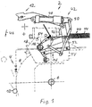
- Fig. 1 shows an embodiment of a measuring device 2 according to the invention, which is used for in-process measurement of test specimens during a machining operation on a grinding machine 4.
- the grinding machine 4 which is only partially shown for reasons of simplicity, has a rotatable about a machine-fixed axis of rotation 6 grinding wheel 8, which serves for processing a test specimen, which is formed in this embodiment by a crank pin 10 of a crankshaft.
- the measuring device 2 has a measuring head 12, which is connected via a linkage 14 about a first pivot axis 16 pivotally connected to a base body 18 of the measuring device 2.
- the measuring device 2 further comprises means for pivoting the measuring head 12 into and out of the measuring position or from the measuring position, which are explained in more detail below.
- the linkage 14 has a first linkage element 20 and a second linkage element 22, which are arranged pivotably about the first pivot axis 16.
- a third linkage element 26 is pivotally connected about a second pivot axis 24, with its fourth end remote from a third pivot axis 28 pivotally connected to a fourth linkage element remote from the third pivot axis 24 Swivel axis 28 is pivotally connected to the first linkage member 20 about a fourth pivot axis.
- the second linkage member 22 has a lever arm 34, such that the lever arm 34 together with the linkage member 22 forms a two-armed angle lever whose function will be explained in more detail below.
- the measuring head 12 is arranged on a holding arm 35, which is connected to the fourth linkage element 30 that extends beyond the fourth pivoting axis 32.
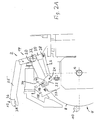
- the connection between the support arm 34 and the fourth linkage element 30 rigidly executed. How out Fig. 2A It can be seen that in the illustrated embodiment, a free end of the holding arm 34 holding the measuring head 12 is angled toward the first pivot axis 16, wherein a part of the holding arm 34 connected to the fourth link element 30 forms an angle of greater than 90 ° with the fourth link element 30 ,
- the measuring head 12 has a linearly displaceable along a linear axis probe 36, which in Fig. 2A is indicated by a dashed line.
- the measuring head 12 also has a measuring prism 38 in the illustrated embodiment.
- the manner in which roundness and / or dimensional measurements are performed on a test specimen, in particular a crank pin of a crankshaft or another cylindrical component, by means of an arrangement of a linearly deflectable probe 36 and a measuring prism 38 is well known to the person skilled in the art and therefore becomes not explained here.
- the measuring device 2 further comprises means for moving the measuring head 12 from a rest position to the measuring position, which in this embodiment comprise means for pivoting the measuring head 12, which engage the linkage 14 and based on Fig. 1 be explained in more detail.
- the means for swiveling in and out of the measuring head 12 have a swivel device 40 and a separate swivel device 42.
- the Einschwenkvoretti 40 spring means which in this embodiment have a trained as a compression spring spring 44, the measuring head 12 via the linkage 14 in a in Fig. 1 by an arrow 46 symbolized Einschwenkraum applied.
- the spring 44 is formed in this embodiment as a compression spring and is supported at its one end on the base body 18 of the measuring device 2 and at its other end on the lever arm 34, so that the spring 44, the lever arm 34 in Fig. 1 counterclockwise and thus the measuring head 12 is acted upon by means of the linkage 14 in the pivoting 46 and seeks to move.
- the swivel device 42 has in this embodiment, a hydraulic cylinder 48, the piston is connected at its free end to the base body 18 of the measuring device 2.
- the piston rod 50 of the hydraulic cylinder 48 formed in this embodiment as a toggle lever assembly 42 is connected, the piston rod 50 facing away from free end to the first pivot axis 16 is eccentrically connected to a one-armed lever 54 which is mounted coaxially to the pivot axis 16.
- the lever 54 has at its free end in the plane extending into a pin 56 which acts on the first linkage member 20 loosely, so that the lever 54 when moving in a Ausschwenkoplasty, which corresponds to a clockwise movement in the drawing, as a driver for the first linkage element 20 acts.
- sensor means For sensing the respective position of the measuring head 12 sensor means are provided which are in operative connection with control means for controlling the Einschwenkvortechnisch 40 and the Ausschwenkvortechnisch 42.
- the measuring head 12 in the pivoting 46 of the hydraulic cylinder 48 is actuated such that its piston rod 50 in Fig. 1 extends to the right.
- the spring 44 presses against the lever arm 34, so that the lever arm 34 in Fig. 2 is pivoted counterclockwise. Since the lever arm 34 is rotatably connected to the second linkage element 22, in this case the second linkage element 22 and thus the entire linkage 14 in Fig. 2 pivoted counterclockwise.
- Fig. 2B shows the measuring head 12 in a position between the rest position and the measuring position.
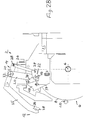
- Fig. 2C When reaching a predetermined, in Fig. 2C illustrated angular position of the lever arm 34 runs on a stop 57, wherein upon emergence of the lever arm 34 on the stop 57, a control signal is transmitted to the control means, due to which the hydraulic cylinder 48 is stopped.
- Fig. 2C shows the measuring head 12 in a search position in which he is not yet in contact with the crank pin 10.
- Fig. 2E corresponds to Fig. 2C wherein the measuring head 12 is shown in its seek position with respect to a larger diameter crank pin 10 '.
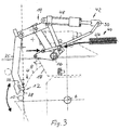
- Fig. 3 shows the measuring device 2 in the search position of the measuring head 12, which also in Fig. 2C is shown.
- Fig. 1 With Fig. 3 results in the lever 54 by means of the lever assembly 42 during extension of the piston rod 50 of the hydraulic cylinder 48 in Fig. 1 pivoted counterclockwise until the in Fig. 3 shown angular position of the lever 54 is reached.
- Fig. 3 can be seen, in this angular position of the pin 56 in the circumferential direction of the first axis of rotation 16 to the first linkage member 20 spaced so that the first linkage member 20 and thus the entire linkage 14 under the action of the weight of the measuring head 12 including the holding arm 34 and the the spring 44 can exert pressure force exerted freely.
- the gauge head 12 abuts the crankpin 10 with the gauge tracking orbital rotation of the crankpin 10 about the crankshaft during the grinding process.
- the base body 18 of the measuring device 2 is fixedly connected with a holder of the grinding wheel 8, so that the measuring device 2 traceable translational movements of the grinding wheel 8 in the radial direction of the axis of rotation 6.
- the measuring probe 36 receives measured values, by means of which the roundness and / or the diameter of the crank pin can be assessed in the evaluation computer 36 downstream of the evaluation computer. For example reaches a certain degree of diameter, the grinding wheel 8 is disengaged from the crankpin 10.
- the measuring head moves in the circumferential direction of the crank pin 10 with an angular stroke, which is in the illustrated embodiment, about -7 ° and + 5 °, ie a total of 12 °.
- Fig. 4 shows block-like components of the measuring device 2 according to the invention, which are used in the calibration.
- the measuring device 2 has a Control device 80, which is designed and arranged such that the measuring device 2 between a measuring mode in which a measuring operation is executed, and a calibration mode in which a calibration process is executable, is switchable.
- the control device 80 is further configured and configured such that the measuring device can be calibrated in a calibration mode.
- the measuring probe 36 continuously records measured values which are fed to an evaluation device 82, which reconstructs the profile of the test object on the basis of the measured values.
- the reconstruction can in particular by means of an iterative method according to the DE 10 2009 032 353 A1 respectively. However, the reconstruction can also be done by means of a Fourier analysis EP 1 263 547 B1 respectively.
- the control device 80 switches the measuring device 2 from the measuring mode into the calibration mode.
- the calibration mode the calibration of the measuring device 2 is performed, in the illustrated embodiment using a patch standard, as described below with reference to FIG Fig. 5 is explained in more detail.
- the patch standard is clamped by means of a suitable tensioning device, to which a rotary drive 84 is assigned, so that the patch standard is rotatable relative to the measuring head 12.
- control device 80 controls the Einschwenkvorraum 40 such that the measuring head 12 is pivoted and the measuring prism 38 and the probe 36 is brought into contact with the Flicknormal. Subsequently, the control device 80 controls the rotary drive 84 of the Flicknormales such that this rotates relative to the probe 36.
- the flick normal scans the flick normal.
- the measured values obtained form calibration data, by means of which a calibration of the measuring device is carried out in a manner explained in more detail below.
- the calibration data are stored in a memory 86 of the control device 80, which is in data transmission connection with the evaluation device 82.
- the controller 82 switches the measuring device 2 back to the measuring mode.
- the Ausschwenkvorraum 42 is driven, which then moves the measuring head 12 from the measuring position back to the rest position.
- the rotary actuator 84 is stopped, so that the Flicknormal can be stretched and clamped to perform a measurement process on a DUT the same.
- the calibration data available to the evaluation device 82 are taken into account in the subsequent measuring process for calibrating the measuring device 2.
- the calibration of the measuring device 2 can, if necessary, and / or after a predetermined number of measuring operations and / or after a predetermined period of operation of the measuring device 2 are made.
- FIG. 4 illustrates a highly schematic view of the measuring prism 38 together with a patch standard 88.
- Fig. 5 is the opening angle of the measuring prism 38 ⁇ (first angle) recognizable. It can also be seen that the flick standard 88 is in contact with the measuring prism 38 at two contact points 94, 96, while the measuring probe 36 is in contact with the flick standard 88 at a contact point located in the circumferential direction of the flick standard 88.
- the symmetry axis of the measuring prism 38 is in Fig. 5 symbolized by a dot-dash line 100 and forms the y-axis of a right-handed Cartesian coordinate system for the following consideration.
- the linear axis of the probe 36 extends at an angle ⁇ (second angle) to the x-axis of this coordinate system.
- ⁇ second angle
- the goal of the evaluation or reconstruction carried out in the evaluation device 82 is to reconstruct the component contour R ( ⁇ ) from the distance function A ( ⁇ ) by calculation.
- the angles ⁇ and ⁇ must be known for the reconstruction. Deviations of the actual values of the angles ⁇ and ⁇ from assumed values of these angles lead to measurement inaccuracies which are avoided by the calibration carried out according to the invention.
- the flick standard 88 has the radius R 0 in the regions in which its contour is circularly delimited, then the smallest component radius R 0 -Pt occurs at the angle ⁇ 0 .
- the flattening of the flick standard always has only one point of contact with the measuring device 2, which however can be readily ensured by appropriate dimensioning of the flattening 90.
- the result is the in Fig. 6 shown function course.
- the transformation rule according to equation (1.1) ensures that the peaks in Fig. 6 have the same shape, but different amplitudes.
- the unknown angles may be determined by identifying the local extrema or performing an integral evaluation of the distance function using the Fourier transform.
- Measurement errors that are based on a deviation of the actual geometric conditions of the measuring device 2 of assumed geometric relationships are thus reliably avoided compared to the prior art.
- the invention thus offers compared to measuring devices of the prior art improved with a relatively low cost measurement accuracy.
- FIGS. 2A to 2E show a structurally slightly modified variant of the embodiment according to Fig. 1 and Fig. 3 However, with respect to the basic principle according to the invention with the embodiment according to Fig. 1 and Fig. 3 matches.
Landscapes
- Physics & Mathematics (AREA)
- General Physics & Mathematics (AREA)
- Engineering & Computer Science (AREA)
- Mechanical Engineering (AREA)
- A Measuring Device Byusing Mechanical Method (AREA)
- Machine Tool Sensing Apparatuses (AREA)
- Constituent Portions Of Griding Lathes, Driving, Sensing And Control (AREA)
- Length Measuring Devices With Unspecified Measuring Means (AREA)
Applications Claiming Priority (1)
| Application Number | Priority Date | Filing Date | Title |
|---|---|---|---|
| DE102012018580.4A DE102012018580B4 (de) | 2012-09-20 | 2012-09-20 | Messvorrichtung und Messverfahren zur Inprozess-Messung an Prüflingen während eines Bearbeitungsvorganges an einer Bearbeitungsmaschine, insbesondere einer Schleifmaschine |
Publications (2)
| Publication Number | Publication Date |
|---|---|
| EP2711132A1 EP2711132A1 (de) | 2014-03-26 |
| EP2711132B1 true EP2711132B1 (de) | 2016-01-20 |
Family
ID=49293415
Family Applications (1)
| Application Number | Title | Priority Date | Filing Date |
|---|---|---|---|
| EP13004469.6A Revoked EP2711132B1 (de) | 2012-09-20 | 2013-09-13 | Messvorrichtung |
Country Status (7)
| Country | Link |
|---|---|
| US (1) | US9562756B2 (enExample) |
| EP (1) | EP2711132B1 (enExample) |
| JP (1) | JP5873470B2 (enExample) |
| CN (1) | CN103769965B (enExample) |
| BR (1) | BR102013024131B1 (enExample) |
| DE (1) | DE102012018580B4 (enExample) |
| RU (1) | RU2581326C2 (enExample) |
Families Citing this family (18)
| Publication number | Priority date | Publication date | Assignee | Title |
|---|---|---|---|---|
| TW201524683A (zh) * | 2013-09-16 | 2015-07-01 | Marposs Spa | 用來檢查銷之直徑尺寸的裝置 |
| DE102013226733B4 (de) * | 2013-12-19 | 2021-12-23 | Erwin Junker Grinding Technology A.S. | VERFAHREN UND SCHLEIFMASCHINE ZUM MESSEN UND ERZEUGEN EINER AUßENSOLLKONTUR EINES WERKSTÜCKES DURCH SCHLEIFEN |
| DE102014118753A1 (de) | 2014-10-01 | 2016-04-07 | Jenoptik Industrial Metrology Germany Gmbh | Prüfvorrichtung |
| DE202014011033U1 (de) * | 2014-12-16 | 2017-06-23 | Jenoptik Industrial Metrology Germany Gmbh | Messvorrichtung |
| JP6537852B2 (ja) * | 2015-03-09 | 2019-07-03 | 株式会社ミツトヨ | 形状測定装置の軸ずれ判定方法、形状測定装置の調整方法、形状測定装置の軸ずれ判定プログラム、および、形状測定装置 |
| DE102016107135A1 (de) | 2016-04-18 | 2017-10-19 | Jenoptik Industrial Metrology Germany Gmbh | Messanordnung |
| DE102016122695A1 (de) | 2016-07-20 | 2018-01-25 | Jenoptik Industrial Metrology Germany Gmbh | Oberflächenmessvorrichtung |
| US11085793B2 (en) * | 2016-10-03 | 2021-08-10 | Government Of The United States Of America, As Represented By The Secretary Of Commerce | Inertial measurement unit and diagnostic system |
| DE102017106741B4 (de) | 2017-03-29 | 2019-11-14 | Jenoptik Industrial Metrology Germany Gmbh | Oberflächenmessgerät |
| JP7000785B2 (ja) * | 2017-10-04 | 2022-01-19 | 株式会社ジェイテクト | 工作機械 |
| DE102018103420A1 (de) | 2018-02-15 | 2019-08-22 | Jenoptik Industrial Metrology Germany Gmbh | Messgerät zur Oberflächen- oder Konturmessung |
| RU190136U1 (ru) * | 2018-07-03 | 2019-06-21 | Акционерное общество (АО) "Научно-исследовательский институт лопастных машин" ("НИИ ЛМ") | Устройство для копирования сложного контура сечения пространственного объекта |
| DE102019105059A1 (de) | 2018-12-19 | 2020-06-25 | Jenoptik Industrial Metrology Germany Gmbh | Verfahren zum Betreiben eines Oberflächenmessgeräts |
| DE102019104949A1 (de) | 2019-01-07 | 2020-07-09 | Jenoptik Industrial Metrology Germany Gmbh | Messkopf einer Messvorrichtung zur Formmessung an wellenartigen Werkstücken |
| DE102020108182A1 (de) | 2019-05-07 | 2020-11-12 | Jenoptik Industrial Metrology Germany Gmbh | Oberflächenmessgerät |
| DE102019135732B4 (de) * | 2019-12-23 | 2021-09-23 | Neura Robotics GmbH | Vorrichtung zur Messung einer Längenänderung |
| CN112247741B (zh) * | 2020-09-25 | 2022-04-08 | 深圳市裕展精密科技有限公司 | 校准系统、校准方法及校准装置 |
| CN115401543B (zh) * | 2022-08-25 | 2023-09-05 | 青岛高测科技股份有限公司 | 磨床及其控制方法及系统、设备、计算机可读存储介质 |
Citations (3)
| Publication number | Priority date | Publication date | Assignee | Title |
|---|---|---|---|---|
| US5077908A (en) | 1987-11-04 | 1992-01-07 | David Moore | Apparatus for measuring the roundness of a surface of an object |
| WO2001066306A1 (en) | 2000-03-06 | 2001-09-13 | Marposs Società per Azioni | Apparatus and method to measure the dimensional and form deviation of crankpins at the place of grinding |
| WO2001066305A1 (en) | 2000-03-06 | 2001-09-13 | Marposs Società per Azioni | Apparatus and methods for measuring the pins diameter of a crankshaft at the place of grinding |
Family Cites Families (161)
| Publication number | Priority date | Publication date | Assignee | Title |
|---|---|---|---|---|
| DE88446C (enExample) | 1896-02-19 | 1896-09-03 | ||
| GB136275A (en) | 1918-12-14 | 1919-12-15 | Samuel Griffin | Automatic Adjustment of Friction Clutches. |
| US1425283A (en) | 1921-04-02 | 1922-08-08 | Frederick J Pratt | Grinding gauge |
| DE347056C (de) | 1921-04-18 | 1922-01-13 | Skf Svenska Kullagerfab Ab | Vorrichtung zum Pruefen des Fortschrittes der Arbeit bei Schleifmaschinen |
| DE441965C (de) | 1926-03-19 | 1927-03-18 | August Blume | Mahlscheiben aus Stahl, Hartguss o. dgl. |
| US1815049A (en) | 1927-07-08 | 1931-07-21 | Norton Co | Work size mechanism for grinding machines |
| US1892005A (en) | 1930-12-15 | 1932-12-27 | Int Harvester Co | Gauge |
| US2003334A (en) | 1931-07-25 | 1935-06-04 | Norton Co | Caliper controlled grinding machine |
| US1947456A (en) | 1931-11-28 | 1934-02-20 | Sattley Company | Coin handling machine |
| US2001447A (en) | 1932-03-12 | 1935-05-14 | Landis Tool Co | Automatic control mechanism |
| BE458323A (enExample) | 1944-04-22 | |||
| FR1005430A (fr) | 1947-07-18 | 1952-04-10 | Gendron Freres Ets | Dispositif d'auto-calibrage pour machine-outil et en particulier pour rectifieuses en plongée |
| US2789354A (en) | 1949-01-21 | 1957-04-23 | Optical Gaging Prod Inc | Profile contour machine |
| US2909873A (en) | 1957-04-29 | 1959-10-27 | James C Fisk | Gauge support |
| US2949708A (en) | 1959-06-24 | 1960-08-23 | Cincinnati Milling Machine Co | Gage head for in-process gaging in machine tool |
| US3157971A (en) | 1963-02-07 | 1964-11-24 | Landis Tool Co | Size control device adaptable to different diameters |
| US3321869A (en) | 1964-07-13 | 1967-05-30 | Farrel Corp | Machine tool |
| NL6410508A (enExample) | 1964-09-09 | 1966-03-10 | ||
| US3274693A (en) | 1965-02-04 | 1966-09-27 | Bendix Corp | Method and apparatus for roundness measurement |
| US3386178A (en) | 1965-08-11 | 1968-06-04 | Philip S. Arnold | Grinding gage |
| US3352022A (en) | 1965-10-11 | 1967-11-14 | James C Fisk | Upright grinding gauge |
| CH451548A (de) | 1966-06-01 | 1968-05-15 | Volpi Ag | Panorama-Objektiv für Aufnahme- oder Projektionszwecke |
| JPS5124892B1 (enExample) | 1969-04-26 | 1976-07-27 | ||
| US3603044A (en) | 1969-06-10 | 1971-09-07 | Litton Industries Inc | Gauge mechanism for grinding machines |
| US3648377A (en) | 1969-06-25 | 1972-03-14 | Bendix Corp | Sling roundness gage |
| US3663190A (en) | 1970-04-22 | 1972-05-16 | James C Fisk | Gauge support |
| US3694970A (en) | 1970-09-18 | 1972-10-03 | Litton Industries Inc | Offset size adjustment circuit for grinding machines |
| JPS519587B1 (enExample) | 1970-12-03 | 1976-03-27 | ||
| GB1320480A (en) | 1971-06-03 | 1973-06-13 | Toyoda Machine Works Ltd | Grinding machine |
| US3802087A (en) | 1971-07-19 | 1974-04-09 | Inductosyn Corp | Measuring apparatus |
| US3863352A (en) | 1973-06-14 | 1975-02-04 | American Gage & Mach | Gaging apparatus with flow control mechanism |
| US3987552A (en) | 1974-07-01 | 1976-10-26 | Inductosyn Corporation | Measuring apparatus |
| US3992615A (en) * | 1975-05-14 | 1976-11-16 | Sun Studs, Inc. | Electro-optical ranging system for distance measurements to moving targets |
| JPS5824223B2 (ja) | 1976-06-30 | 1983-05-19 | 豊田工機株式会社 | クランクピンの位置決め方法および装置 |
| US4141149A (en) | 1976-09-30 | 1979-02-27 | Gravure Research Institute, Inc. | Portable comparator gage for measuring the relative deviation in the diameter of cylinders |
| US4106241A (en) | 1976-10-28 | 1978-08-15 | Fisk James C | Grinding gauge support |
| US4175462A (en) | 1977-06-17 | 1979-11-27 | Simon Jonathan C | System for selection and phase control of humbucking coils in guitar pickups |
| JPS6055258B2 (ja) | 1979-02-28 | 1985-12-04 | トヨタ自動車株式会社 | 長尺物の円筒研削方法 |
| IT1120335B (it) | 1979-04-05 | 1986-03-19 | Finike Italiana Marposs | Apparecchiatura per il controllo di dimensioni lineari di alberi |
| JPS5841042Y2 (ja) | 1979-04-13 | 1983-09-16 | 豊田工機株式会社 | 心押台 |
| FR2464456A1 (fr) * | 1979-08-29 | 1981-03-06 | Onera (Off Nat Aerospatiale) | Appareil de metrologie capacitive pour la mesure de sections droites d'une piece |
| US4394683A (en) | 1980-06-26 | 1983-07-19 | Diffracto Ltd. | New photodetector array based optical measurement systems |
| GB2086778B (en) | 1980-10-28 | 1984-02-22 | Landis Lund Ltd | Method and apparatus for indexing of a crankshaft |
| IT1135893B (it) | 1980-12-23 | 1986-08-27 | Finike Italiana Marposs | Dispositivo di misura per il controllo dimensionale di un pezzo meccanico |
| DE3121609A1 (de) | 1981-05-30 | 1982-12-23 | Naxos-Union Schleifmittel- Und Schleifmaschinenfabrik, 6000 Frankfurt | Schleifmaschine fuer hublager |
| DE3123489A1 (de) | 1981-06-13 | 1982-12-30 | Dr. Johannes Heidenhain Gmbh, 8225 Traunreut | Verfahren zur messung der rundheitsabweichungen von rotationskoerpern und einrichtungen zur durchfuehrung des verfahrens |
| US4429464A (en) | 1982-01-29 | 1984-02-07 | Burrus Brice M | Roundness calibration standard |
| US4414748A (en) | 1982-02-16 | 1983-11-15 | The Unites States Of America As Represented By The Department Of Energy | Ball mounting fixture for a roundness gage |
| CH647189A5 (fr) | 1982-06-03 | 1985-01-15 | Meseltron Sa | Dispositif de manipulation d'une piece cylindrique ou spherique. |
| US4480412A (en) | 1982-09-03 | 1984-11-06 | Litton Industrial Products, Inc. | In-process grinding gage |
| DE3232904A1 (de) | 1982-09-04 | 1984-03-08 | Robert Bosch Gmbh, 7000 Stuttgart | Sonde zum automatischen pruefen von oberflaechen |
| JPS5993844U (ja) | 1982-12-16 | 1984-06-26 | 豊田工機株式会社 | クランクピン割出精度確認装置 |
| HU192125B (en) | 1983-02-08 | 1987-05-28 | Budapesti Mueszaki Egyetem | Block of forming image for centre theory projection adn reproduction of spaces |
| JPS59125001U (ja) | 1983-02-14 | 1984-08-23 | 三洋電機株式会社 | 充電式灯器 |
| US4524546A (en) | 1983-06-06 | 1985-06-25 | Armco Inc | Roll profile gauge |
| US4493168A (en) * | 1983-06-16 | 1985-01-15 | Coburn Optical Industries, Inc. | Calibration gauge for computer-controlled lens generator, or the like |
| IT1183093B (it) | 1984-01-13 | 1987-10-05 | Schaudt Maschinenbau Gmbh | Testa di misurazione per rettificatrici |
| DE8425377U1 (de) | 1984-07-03 | 1986-04-17 | Schaudt Maschinenbau Gmbh, 7000 Stuttgart | Schleifmaschine zum meßgesteuerten Gewindeschleifen |
| US4637144A (en) | 1984-07-03 | 1987-01-20 | Schaudt Maschinenbau Gmbh | Apparatus for monitoring the diameters of crankpins during treatment in grinding machines |
| IT1180539B (it) | 1984-10-15 | 1987-09-23 | Finike Italiana Marposs | Testa per il controllo di dimensioni pezzi meccanici |
| DE3511564A1 (de) | 1985-03-29 | 1986-10-02 | Hommelwerke GmbH, 7730 Villingen-Schwenningen | Einrichtung zur messung der kreisformabweichung exzentrischer lagerflaechen, insbesondere von pleuellagern |
| US4679331A (en) | 1985-08-26 | 1987-07-14 | Ppg Industries, Inc. | Apparatus and method for determining contour characteristics of a contoured article |
| GB8603060D0 (en) | 1986-02-07 | 1986-03-12 | Rank Taylor Hobson Ltd | Usefulness of in situ roundness measurement |
| IT1191690B (it) | 1986-03-20 | 1988-03-23 | Giustina International Spa | Apparato di misura indipendente per macchine rettificatrici per cilindri e simili con organi di controllo strutturale e superficiale |
| GB8625702D0 (en) | 1986-10-28 | 1986-12-03 | Armstrong D A | Profile gauging |
| US4819195A (en) | 1987-01-20 | 1989-04-04 | The Warner & Swasey Company | Method for calibrating a coordinate measuring machine and the like and system therefor |
| IT1213718B (it) | 1987-11-09 | 1989-12-29 | Marposs Spa | Apparecchio per il controllo di caratteristiche di pezzi a simmetria di rotazioni |
| IT1213698B (it) | 1987-10-09 | 1989-12-29 | Marposs Spa | Apparecchio a grande campo per il controllo di dimensioni lineari di pezzi |
| GB8728016D0 (en) * | 1987-11-30 | 1988-01-06 | Grosvenor R I | Methods and apparatus for measuring transverse dimensions of workpieces |
| US4949469A (en) * | 1988-07-01 | 1990-08-21 | Albion Devices, Inc. | Temperature-compensated quantitative dimensional measurement device with rapid temperature sensing and compensation |
| IT1225040B (it) | 1988-08-11 | 1990-11-02 | Marposs Spa | Apparecchio per il controllo di caratteristiche di pezzi |
| DE3828181A1 (de) | 1988-08-19 | 1990-03-08 | Voith Gmbh J M | Messvorrichtung, insbesondere zur messung der durchmesser von walzen bei walzenschleifmaschinen |
| FR2636877B1 (fr) | 1988-09-27 | 1994-07-01 | Procedes Machines Speciales | Machine pour l'usinage par abrasif de portees cylindriques sur des pieces, notamment pour l'usinage par toilage des tourillons et manetons sur des vilebrequins |
| DE3841439A1 (de) | 1988-12-09 | 1990-06-13 | Pietzsch Automatisierungstech | Vorrichtung zum gleichzeitigen vermessen hintereinanderliegender zylinderbohrungen |
| DE3900106C2 (de) | 1989-01-04 | 1994-01-05 | Bbc Pat Mestechnik Gmbh | Verfahren und Vorrichtung zum Vermessen der Form von Zylinderbohrungen in Werkstücken |
| US5095663A (en) | 1989-02-07 | 1992-03-17 | Industrial Metal Products Corporation | Size control shoe for microfinishing machine |
| AT393029B (de) | 1989-03-29 | 1991-07-25 | Rsf Elektronik Gmbh | Inkrementales laengenmesssystem |
| US5088207A (en) | 1989-12-13 | 1992-02-18 | Betsill Harry E | True end-to-end electronic saddle micrometer |
| US5097602A (en) | 1990-07-09 | 1992-03-24 | Westinghouse Electric Corp. | Apparatus and method for automated inspection of a surface contour on a workpiece |
| FR2665526A1 (fr) | 1990-08-02 | 1992-02-07 | Meseltron Sa | Dispositif pour la mesure de diametres de pieces cylindriques en cours d'usinage. |
| DE4025522A1 (de) | 1990-08-11 | 1992-02-13 | Wolter Doll Dieter | Verfahren und vorrichtung zur erkennung von bearbeitungsfehlern, insbesondere von schleifmaschinen |
| US6205371B1 (en) | 1990-08-11 | 2001-03-20 | Dieter Wolter-Doll | Method and apparatus for detecting machining flaws, especially caused by grinding machines |
| US5136527A (en) | 1990-10-05 | 1992-08-04 | Precision Devices, Inc. | Surface finish measuring device and method for gear teeth |
| DE4031931A1 (de) | 1990-10-06 | 1992-04-09 | Perthen Feinpruef Gmbh | Induktiver laengenmesstaster |
| DK16791D0 (da) | 1991-01-30 | 1991-01-30 | Leif Groenskov | Fremgangsmaade og middel til maaling af et profil |
| US5099585A (en) | 1991-02-19 | 1992-03-31 | Control Gaging, Inc. | In-process machine gage |
| US5337485A (en) | 1992-01-28 | 1994-08-16 | Chien An Y | Roundness error and crown electronic measuring system |
| AU665048B2 (en) | 1992-02-14 | 1995-12-14 | Toyota Jidosha Kabushiki Kaisha | Apparatus and method for feedback-adjusting working condition for improving dimensional accuracy of processed workpieces |
| JP3246961B2 (ja) | 1992-11-05 | 2002-01-15 | 株式会社小松製作所 | クランクシャフトミラーの制御装置 |
| IT1266221B1 (it) | 1993-01-21 | 1996-12-27 | Marposs Spa | Apparecchiatura per il controllo geometrico di pezzi a simmetria di rotazione |
| US5914593A (en) | 1993-06-21 | 1999-06-22 | Micro Strain Company, Inc. | Temperature gradient compensation circuit |
| DE4320845C1 (de) | 1993-06-23 | 1994-10-27 | Fraunhofer Ges Forschung | Anordnung zur Messung von Streulicht in Bohrungen von Werkstücken oder in Rohren |
| US5473474A (en) | 1993-07-16 | 1995-12-05 | National Research Council Of Canada | Panoramic lens |
| US5419056A (en) | 1993-07-29 | 1995-05-30 | Thomas E. Breitenstein | Centerless gaging apparatus for checking the concentricity and straightness of shank-type tools and the like |
| JP3386548B2 (ja) * | 1994-01-31 | 2003-03-17 | トヨタ自動車株式会社 | フィードバック式加工条件補正装置 |
| DE4412682C2 (de) * | 1994-04-13 | 1998-09-03 | Doerries Scharmann Ag I K | Vorrichtung zum Vermessen exzentrisch umlaufender Werkstücke |
| DE4416493A1 (de) | 1994-05-10 | 1995-11-16 | Bosch Gmbh Robert | Oberflächenprüfvorrichtung |
| DE4419656C2 (de) | 1994-06-06 | 1996-05-15 | Naxos Union Schleifmittel | Einrichtung zur Durchmesser- und/oder Rundheitsmessung beim exzentrischen Rundschleifen |
| DE4420137A1 (de) | 1994-06-09 | 1995-12-14 | Zeiss Messgeraetebau Gmbh | Meßgerät zur Überprüfung der Abmessungen von zylindrischen Werkstücken |
| US5479096A (en) | 1994-08-08 | 1995-12-26 | Lucas Industries, Inc. | Analog sensing system with digital temperature and measurement gain and offset correction |
| US5551906A (en) | 1994-11-23 | 1996-09-03 | Voith Sulzer Paper Technology North America Inc. | Caliper assembly for grinder |
| GB9509294D0 (en) | 1995-05-06 | 1995-06-28 | Western Atlas Uk Ltd | Improvements relating to guaging the diameter of cylindrical workpiece sections |
| IT1279641B1 (it) | 1995-10-03 | 1997-12-16 | Marposs Spa | Apparecchio per il controllo del diametro di perni di biella in moto orbitale |
| DE69608291T2 (de) | 1995-10-06 | 2001-01-04 | Etamic S.A., Saint-Martin-Des-Entrees | Mess-und regelgerät für die bearbeitung von umlaufenden zylindrischen werkstücken |
| GB9612383D0 (en) | 1995-12-07 | 1996-08-14 | Rank Taylor Hobson Ltd | Surface form measurement |
| DE19602470A1 (de) | 1996-01-24 | 1997-07-31 | Siemens Ag | Bestimmung und Optimierung der Arbeitsgenauigkeit einer Werkzeugmaschine oder eines Roboters oder dergleichen |
| US6062948A (en) | 1996-04-19 | 2000-05-16 | Schmitt Measurement Systems, Inc. | Apparatus and method for gauging a workpiece |
| GB9608352D0 (en) | 1996-04-23 | 1996-06-26 | Western Atlas Uk Ltd | Workpiece grinding method and apparatus |
| US5785770A (en) | 1996-05-30 | 1998-07-28 | Advance Research Chemicals, Inc. | Brazing flux |
| JPH09323257A (ja) | 1996-05-31 | 1997-12-16 | Toshiba Mach Co Ltd | ロール研削盤におけるロール径計測方法およびロール径計測装置 |
| US5902925A (en) | 1996-07-01 | 1999-05-11 | Integrated Sensor Solutions | System and method for high accuracy calibration of a sensor for offset and sensitivity variation with temperature |
| US5919081A (en) | 1996-09-04 | 1999-07-06 | Unova Ip Corporation | Method and apparatus for computer numerically controlled pin grinder gauge |
| JPH10118974A (ja) | 1996-10-14 | 1998-05-12 | M Alpha Giken:Kk | 多関節ロボットにおけるハンドの回転位置検出装置 |
| KR19980053785U (ko) | 1996-12-31 | 1998-10-07 | 추호석 | 공작기계의 공구 보정장치 |
| DE19712622C5 (de) | 1997-03-26 | 2010-07-15 | Dr. Johannes Heidenhain Gmbh | Anordnung und Verfahren zur automatischen Korrektur fehlerbehafteter Abtastsignale inkrementaler Positionsmeßeinrichtungen |
| EP0878704B1 (de) | 1997-05-13 | 2005-11-09 | Gretag-Macbeth AG | Remissionsmessvorrichtung |
| DE19740141C1 (de) | 1997-09-12 | 1999-04-29 | Daimler Chrysler Ag | Verfahren zur Ermittlung einer Drallstruktur in der Oberflächenrauheit eines feinbearbeiteten Wellenzapfens |
| ES2189094T3 (es) | 1997-09-23 | 2003-07-01 | Unova Uk Ltd | Perfeccionamientos relativos a la calibracion en piezas a mecanizar. |
| WO1999047884A1 (en) | 1998-03-13 | 1999-09-23 | Marposs Societa' Per Azioni | Head, system and method for the linear dimension checking of a mechanical piece |
| KR100264247B1 (ko) | 1998-03-28 | 2000-08-16 | 김영삼 | 공작기계의 열변형오차 측정 및 보정시스템 |
| IT1298976B1 (it) | 1998-03-31 | 2000-02-07 | Balance Systems Spa | Apparato di misura di pezzi in lavorazione, particolarmente per macchine rettificatrici |
| US6321171B1 (en) | 1998-04-03 | 2001-11-20 | Tektronix, Inc. | Electronic measurement instrument probe accessory offset, gain, and linearity correction method |
| US6029363A (en) | 1998-04-03 | 2000-02-29 | Mitutoyo Corporation | Self-calibrating position transducer system and method |
| US6116269A (en) | 1998-07-07 | 2000-09-12 | Fasco Controls Corporation | Solenoid pressure transducer |
| US6159074A (en) | 1999-01-07 | 2000-12-12 | Kube; Samuel C. | Caliper assembly for a grinding machine |
| WO2000050841A1 (fr) | 1999-02-22 | 2000-08-31 | Obschestvo S Ogranichennoi Otvetstvennostiju 'tekhnomash' | Procede et dispositif permettant de mesurer les inclinaisons de la forme geometrique d'une piece cylindrique, lunette de correction et variantes |
| NO312567B1 (no) | 1999-05-27 | 2002-05-27 | Det Norske Veritas As | Fremgangsmåte ved måling av materialtykkelsesfordeling |
| JP4487387B2 (ja) * | 1999-06-25 | 2010-06-23 | 株式会社ジェイテクト | 真円度測定装置 |
| US6304827B1 (en) | 1999-09-16 | 2001-10-16 | Sensonor Asa | Sensor calibration |
| DE19952592C1 (de) | 1999-11-02 | 2001-05-10 | Hommelwerke Gmbh | Taster zur Abtastung des Verlaufs einer Oberfläche eines Werkstücks |
| ITBO20000012A1 (it) | 2000-01-18 | 2001-07-18 | Marposs Spa | Apparecchiatura per il controllo del diametro di perni . |
| DE10006372A1 (de) | 2000-02-12 | 2001-08-16 | Hauni Maschinenbau Ag | Verfahren und Vorrichtung zum fortlaufenden Verdichten eines bewegten Stromes aus Filtermaterial |
| DE10018107A1 (de) | 2000-04-12 | 2001-10-25 | Helios Mestechnik Gmbh & Co Kg | Vorrichtung und Verfahren zum dreidimensionalen Vermessen von Objekten |
| JP4051872B2 (ja) | 2000-09-29 | 2008-02-27 | 株式会社ジェイテクト | 加工部の測定方法及び加工方法 |
| US20020066179A1 (en) | 2000-12-01 | 2002-06-06 | Hall Hendley W. | System and method for metalization of deep vias |
| ITBO20010113A1 (it) | 2001-03-02 | 2002-09-02 | Marposs Spa | Apparecchiatura per il controllo di caratteristiche dimensionali e geometriche di perni |
| JP2002307268A (ja) | 2001-04-19 | 2002-10-23 | Toyoda Mach Works Ltd | 測定装置を用いた工作物の偏心円筒部の加工方法及び加工装置 |
| ITBO20010268A1 (it) | 2001-05-07 | 2002-11-07 | Marposs Spa | Apparecchiatura per il controllo del diametro di porzioni eccentrichedi un pezzo meccanico durante la lavorazione su una rettificatrice |
| US6487787B1 (en) | 2001-08-03 | 2002-12-03 | Mitutoyo Corporation | System and method for determination of error parameters for performing self-calibration and other functions without an external position reference in a transducer |
| JP3377995B1 (ja) | 2001-11-29 | 2003-02-17 | 株式会社立山アールアンドディ | パノラマ撮像レンズ |
| DE10205212A1 (de) * | 2002-02-08 | 2003-08-21 | Heller Geb Gmbh Maschf | Meßeinrichtung für Maschinen zum Bearbeiten von Werkstücken, insbesondere von Kurbelwellen, Nockenwellen |
| US6560890B1 (en) | 2002-02-21 | 2003-05-13 | General Electric Company | Fixture for locating and clamping a part for laser drilling |
| ITBO20020369A1 (it) | 2002-06-12 | 2003-12-12 | Marposs Spa | Apparecchiatura per il controllo di caratteristiche dimensionali e geometriche di perni |
| US6859756B2 (en) | 2002-09-06 | 2005-02-22 | Red X Holdings Llc | Diagnostic method for manufacturing processes |
| DE20214856U1 (de) | 2002-09-26 | 2003-01-02 | BBi Brunnen- und Bohrlochinspektion GmbH, 39245 Gommern | Bohrlochsonde zur optischen Erfassung der inneren Wandung von Bohrlöchern und Schächten |
| JP4163545B2 (ja) * | 2003-04-11 | 2008-10-08 | 株式会社ミツトヨ | 真円度測定機用基準治具 |
| DE102005045374A1 (de) | 2005-09-22 | 2007-04-05 | Siemens Ag | Messvorrichtung mit einem Messkopf zur Positionsbestimmung eines Primärteils auf einem Sekundärteil und Verfahren zur Positionsbestimmung eines Primärteils auf einem Sekundärteil mit einem Messkopf |
| ITBO20060118A1 (it) | 2006-02-16 | 2007-08-17 | Marposs Spa | Comparatore per il controllo di dimensioni radiali di pezzi meccanici. |
| DE102007031358B4 (de) | 2007-07-05 | 2023-03-16 | Jenoptik Industrial Metrology Germany Gmbh | Vorrichtung zur Abbildung der Innenfläche eines zylindrischen Hohlraums |
| DE102008016228A1 (de) | 2008-03-27 | 2009-10-08 | Hollinger Maschinen Gmbh | Eckenverputzmaschine sowie Verfahren zum Bearbeiten von Ecken eines verschweißten Profilrahmens |
| DE102009019459B4 (de) | 2009-05-04 | 2012-02-02 | Hommel-Etamic Gmbh | Vorrichtung zur Abbildung der Innenfläche eines Hohlraumes in einem Werkstück |
| JP5292564B2 (ja) * | 2009-05-18 | 2013-09-18 | 株式会社ミツトヨ | 形状測定装置、その校正方法、及び校正プログラム |
| DE102009032353A1 (de) | 2009-07-08 | 2011-09-08 | Hommel-Etamic Gmbh | Verfahren zur Ermittlung der Form eines Werkstücks |
| RU2010148768A (ru) * | 2009-07-28 | 2013-09-10 | Комацу Нтк Лтд. | Шлифованный станок и измерительный прибор |
| DE102009042252B4 (de) | 2009-09-22 | 2014-03-06 | Jenoptik Industrial Metrology Germany Gmbh | Meßvorrichtung |
| DE102009052254A1 (de) | 2009-11-06 | 2011-05-12 | Behr Gmbh & Co. Kg | Energiespeichervorrichtung |
| DE102010013069B4 (de) | 2010-03-26 | 2012-12-06 | Hommel-Etamic Gmbh | Meßvorrichtung |
| DE102010018820B3 (de) | 2010-04-29 | 2011-10-13 | Hommel-Etamic Gmbh | Verfahren zur Ermittlung einer Drallstruktur |
| JP5494267B2 (ja) * | 2010-06-15 | 2014-05-14 | セイコーエプソン株式会社 | 三次元形状計測装置、三次元形状計測装置のキャリブレーション方法、およびロボット装置 |
| DE102010035147B4 (de) * | 2010-08-23 | 2016-07-28 | Jenoptik Industrial Metrology Germany Gmbh | Meßvorrichtung |
| DE102011013089A1 (de) | 2011-03-04 | 2012-09-06 | Hommel-Etamic Gmbh | Kurbelwellen-Prüfverfahren |
-
2012
- 2012-09-20 DE DE102012018580.4A patent/DE102012018580B4/de active Active
-
2013
- 2013-09-13 EP EP13004469.6A patent/EP2711132B1/de not_active Revoked
- 2013-09-17 CN CN201310424817.7A patent/CN103769965B/zh active Active
- 2013-09-18 JP JP2013192646A patent/JP5873470B2/ja active Active
- 2013-09-19 RU RU2013142727/02A patent/RU2581326C2/ru active
- 2013-09-20 BR BR102013024131-8A patent/BR102013024131B1/pt active IP Right Grant
- 2013-09-20 US US14/032,571 patent/US9562756B2/en active Active
Patent Citations (3)
| Publication number | Priority date | Publication date | Assignee | Title |
|---|---|---|---|---|
| US5077908A (en) | 1987-11-04 | 1992-01-07 | David Moore | Apparatus for measuring the roundness of a surface of an object |
| WO2001066306A1 (en) | 2000-03-06 | 2001-09-13 | Marposs Società per Azioni | Apparatus and method to measure the dimensional and form deviation of crankpins at the place of grinding |
| WO2001066305A1 (en) | 2000-03-06 | 2001-09-13 | Marposs Società per Azioni | Apparatus and methods for measuring the pins diameter of a crankshaft at the place of grinding |
Non-Patent Citations (5)
| Title |
|---|
| "- Operatinq Instructions Annex 6 (A6) Manual D917N342G1", FENAR L BIG CRANKSHAFTS, 2011, XP055325261 |
| "Manual D2910299GA", MANUAL D2910299GA - MARPOSS SHAPE CONTROL, October 2008 (2008-10-01), XP055325258 |
| MANUAL D2910201 UC - OPERATOR GUIDE, 9 November 2008 (2008-11-09), XP055325264 |
| MANUAL D2910201 UD - PROGRAMMING MANUAL |
| MARPOSS: "Fenar L", BROCHURE, October 2005 (2005-10-01), pages 1 - 4, XP055318068 |
Also Published As
| Publication number | Publication date |
|---|---|
| BR102013024131A2 (pt) | 2014-10-14 |
| US20140083162A1 (en) | 2014-03-27 |
| DE102012018580A1 (de) | 2014-03-20 |
| RU2013142727A (ru) | 2015-04-10 |
| BR102013024131B1 (pt) | 2021-09-08 |
| EP2711132A1 (de) | 2014-03-26 |
| CN103769965A (zh) | 2014-05-07 |
| JP5873470B2 (ja) | 2016-03-01 |
| JP2014061590A (ja) | 2014-04-10 |
| RU2581326C2 (ru) | 2016-04-20 |
| US9562756B2 (en) | 2017-02-07 |
| DE102012018580B4 (de) | 2015-06-11 |
| CN103769965B (zh) | 2017-03-01 |
Similar Documents
| Publication | Publication Date | Title |
|---|---|---|
| EP2711132B1 (de) | Messvorrichtung | |
| EP2298497B1 (de) | Inprozeß-Meßvorrichtung für das Schleifen von Kurbelwellenzapfen | |
| DE102010013069B4 (de) | Meßvorrichtung | |
| DE19521369C2 (de) | Bearbeitungsmaschine zum Umformen von Werkstücken | |
| EP2998691B1 (de) | Kurbellagerflanken-messvorrichtung | |
| EP2092991B1 (de) | Biegegesenk für eine Biegepresse, insbesondere Abkantpresse und Verfahren zum Abkanten eines Werkstücks | |
| DE102010035147A1 (de) | Meßvorrichtung | |
| DE102013010866A1 (de) | Bodenfräsmaschine mit einer Sensoreinrichtung zur berührungslosen Bestimmung von Verschleiß an Meißeleinrichtungen und Verfahren zur berührungslosen Bestimmung von Verschleiß an Meißeleinrichtungen einer Bodenfräsmaschine | |
| DE102014110801B4 (de) | Verfahren zur Ausrichtung eines an einem Koordinatenmessgerät angeordneten Rauheitssensors sowie Koordinatenmessgerät zur Durchführung des Verfahrens | |
| DE102018005304A1 (de) | Werkzeugmaschine und Nullpunkt-Korrekturverfahren | |
| DE4419656C2 (de) | Einrichtung zur Durchmesser- und/oder Rundheitsmessung beim exzentrischen Rundschleifen | |
| EP2036645A2 (de) | Schlittenanordnung für eine Werkzeugmaschine | |
| DE2626079A1 (de) | Vorrichtung zur messung geometrischer abmessungen und/oder fehler | |
| EP3254801A1 (de) | Lünette mit einer kraftmesseinrichtung | |
| WO2019110051A9 (de) | Anordnung für ein messsystem zum messen an einem messobjekt und verfahren zum messen an einem messobjekt mittels eines messsystems | |
| WO2018215556A1 (de) | Spannvorrichtung zum fixieren eines werkstücks sowie werkzeugmaschine mit einer derartigen spannvorrichtung | |
| DE19828675C2 (de) | Verfahren und Vorrichtung zum Einstellen von mittels eines Verstellmechanismus translatorisch verstellbaren Richtrollen eines Richtapparates zum Richten von Draht | |
| DE10006512C2 (de) | Vorrichtung für eine Abkantpresse zum Messen des Biegewinkels am Werkstück | |
| EP2871445B1 (de) | Vorrichtung zur Finishbearbeitung eines Werkstücks | |
| AT396838B (de) | Winkelmessgerät | |
| EP4186610B1 (de) | Rollfalzkopf zum befestigen an einem roboterarm und system umfassend einen rollfalzkopf und einen roboter mit einem roboterarm | |
| DE102019104949A1 (de) | Messkopf einer Messvorrichtung zur Formmessung an wellenartigen Werkstücken | |
| WO2011035864A1 (de) | Inprozess-messvorrichtung für das schleifen von kurbelwellenzapfen | |
| DE102014105714B4 (de) | Einstellvorrichtung zur Einstellung von Stabmessern in einem Werkzeughalter für eine Bearbeitung von Kegelrädern | |
| DE102020211956B4 (de) | Werkzeugschneidkantenmessvorrichtung und Werkzeugmaschine |
Legal Events
| Date | Code | Title | Description |
|---|---|---|---|
| PUAI | Public reference made under article 153(3) epc to a published international application that has entered the european phase |
Free format text: ORIGINAL CODE: 0009012 |
|
| AK | Designated contracting states |
Kind code of ref document: A1 Designated state(s): AL AT BE BG CH CY CZ DE DK EE ES FI FR GB GR HR HU IE IS IT LI LT LU LV MC MK MT NL NO PL PT RO RS SE SI SK SM TR |
|
| AX | Request for extension of the european patent |
Extension state: BA ME |
|
| 17P | Request for examination filed |
Effective date: 20140926 |
|
| RBV | Designated contracting states (corrected) |
Designated state(s): AL AT BE BG CH CY CZ DE DK EE ES FI FR GB GR HR HU IE IS IT LI LT LU LV MC MK MT NL NO PL PT RO RS SE SI SK SM TR |
|
| 17Q | First examination report despatched |
Effective date: 20141209 |
|
| REG | Reference to a national code |
Ref country code: DE Ref legal event code: R079 Ref document number: 502013001822 Country of ref document: DE Free format text: PREVIOUS MAIN CLASS: B24B0049040000 Ipc: G01B0005100000 |
|
| GRAP | Despatch of communication of intention to grant a patent |
Free format text: ORIGINAL CODE: EPIDOSNIGR1 |
|
| RIC1 | Information provided on ipc code assigned before grant |
Ipc: G01B 5/10 20060101AFI20150708BHEP Ipc: G01B 5/20 20060101ALI20150708BHEP Ipc: G01B 5/08 20060101ALI20150708BHEP |
|
| INTG | Intention to grant announced |
Effective date: 20150724 |
|
| GRAS | Grant fee paid |
Free format text: ORIGINAL CODE: EPIDOSNIGR3 |
|
| GRAA | (expected) grant |
Free format text: ORIGINAL CODE: 0009210 |
|
| AK | Designated contracting states |
Kind code of ref document: B1 Designated state(s): AL AT BE BG CH CY CZ DE DK EE ES FI FR GB GR HR HU IE IS IT LI LT LU LV MC MK MT NL NO PL PT RO RS SE SI SK SM TR |
|
| REG | Reference to a national code |
Ref country code: GB Ref legal event code: FG4D Free format text: NOT ENGLISH |
|
| REG | Reference to a national code |
Ref country code: CH Ref legal event code: EP |
|
| REG | Reference to a national code |
Ref country code: IE Ref legal event code: FG4D Free format text: LANGUAGE OF EP DOCUMENT: GERMAN |
|
| REG | Reference to a national code |
Ref country code: AT Ref legal event code: REF Ref document number: 771930 Country of ref document: AT Kind code of ref document: T Effective date: 20160215 |
|
| REG | Reference to a national code |
Ref country code: DE Ref legal event code: R096 Ref document number: 502013001822 Country of ref document: DE |
|
| REG | Reference to a national code |
Ref country code: LT Ref legal event code: MG4D Ref country code: NL Ref legal event code: MP Effective date: 20160120 |
|
| REG | Reference to a national code |
Ref country code: DE Ref legal event code: R082 Ref document number: 502013001822 Country of ref document: DE Representative=s name: MANITZ FINSTERWALD PATENT- UND RECHTSANWALTSPA, DE Ref country code: DE Ref legal event code: R082 Ref document number: 502013001822 Country of ref document: DE Representative=s name: WAGNER, CARSTEN, DIPL.-ING. (UNIV.), DE |
|
| PG25 | Lapsed in a contracting state [announced via postgrant information from national office to epo] |
Ref country code: NL Free format text: LAPSE BECAUSE OF FAILURE TO SUBMIT A TRANSLATION OF THE DESCRIPTION OR TO PAY THE FEE WITHIN THE PRESCRIBED TIME-LIMIT Effective date: 20160120 |
|
| PG25 | Lapsed in a contracting state [announced via postgrant information from national office to epo] |
Ref country code: HR Free format text: LAPSE BECAUSE OF FAILURE TO SUBMIT A TRANSLATION OF THE DESCRIPTION OR TO PAY THE FEE WITHIN THE PRESCRIBED TIME-LIMIT Effective date: 20160120 Ref country code: GR Free format text: LAPSE BECAUSE OF FAILURE TO SUBMIT A TRANSLATION OF THE DESCRIPTION OR TO PAY THE FEE WITHIN THE PRESCRIBED TIME-LIMIT Effective date: 20160421 Ref country code: NO Free format text: LAPSE BECAUSE OF FAILURE TO SUBMIT A TRANSLATION OF THE DESCRIPTION OR TO PAY THE FEE WITHIN THE PRESCRIBED TIME-LIMIT Effective date: 20160420 Ref country code: FI Free format text: LAPSE BECAUSE OF FAILURE TO SUBMIT A TRANSLATION OF THE DESCRIPTION OR TO PAY THE FEE WITHIN THE PRESCRIBED TIME-LIMIT Effective date: 20160120 Ref country code: ES Free format text: LAPSE BECAUSE OF FAILURE TO SUBMIT A TRANSLATION OF THE DESCRIPTION OR TO PAY THE FEE WITHIN THE PRESCRIBED TIME-LIMIT Effective date: 20160120 |
|
| PG25 | Lapsed in a contracting state [announced via postgrant information from national office to epo] |
Ref country code: IS Free format text: LAPSE BECAUSE OF FAILURE TO SUBMIT A TRANSLATION OF THE DESCRIPTION OR TO PAY THE FEE WITHIN THE PRESCRIBED TIME-LIMIT Effective date: 20160520 Ref country code: RS Free format text: LAPSE BECAUSE OF FAILURE TO SUBMIT A TRANSLATION OF THE DESCRIPTION OR TO PAY THE FEE WITHIN THE PRESCRIBED TIME-LIMIT Effective date: 20160120 Ref country code: PT Free format text: LAPSE BECAUSE OF FAILURE TO SUBMIT A TRANSLATION OF THE DESCRIPTION OR TO PAY THE FEE WITHIN THE PRESCRIBED TIME-LIMIT Effective date: 20160520 Ref country code: LT Free format text: LAPSE BECAUSE OF FAILURE TO SUBMIT A TRANSLATION OF THE DESCRIPTION OR TO PAY THE FEE WITHIN THE PRESCRIBED TIME-LIMIT Effective date: 20160120 Ref country code: SE Free format text: LAPSE BECAUSE OF FAILURE TO SUBMIT A TRANSLATION OF THE DESCRIPTION OR TO PAY THE FEE WITHIN THE PRESCRIBED TIME-LIMIT Effective date: 20160120 Ref country code: PL Free format text: LAPSE BECAUSE OF FAILURE TO SUBMIT A TRANSLATION OF THE DESCRIPTION OR TO PAY THE FEE WITHIN THE PRESCRIBED TIME-LIMIT Effective date: 20160120 Ref country code: LV Free format text: LAPSE BECAUSE OF FAILURE TO SUBMIT A TRANSLATION OF THE DESCRIPTION OR TO PAY THE FEE WITHIN THE PRESCRIBED TIME-LIMIT Effective date: 20160120 |
|
| REG | Reference to a national code |
Ref country code: DE Ref legal event code: R026 Ref document number: 502013001822 Country of ref document: DE |
|
| PLBI | Opposition filed |
Free format text: ORIGINAL CODE: 0009260 |
|
| PG25 | Lapsed in a contracting state [announced via postgrant information from national office to epo] |
Ref country code: DK Free format text: LAPSE BECAUSE OF FAILURE TO SUBMIT A TRANSLATION OF THE DESCRIPTION OR TO PAY THE FEE WITHIN THE PRESCRIBED TIME-LIMIT Effective date: 20160120 Ref country code: EE Free format text: LAPSE BECAUSE OF FAILURE TO SUBMIT A TRANSLATION OF THE DESCRIPTION OR TO PAY THE FEE WITHIN THE PRESCRIBED TIME-LIMIT Effective date: 20160120 |
|
| 26 | Opposition filed |
Opponent name: MARPOSS SOCIETA PER AZIONI Effective date: 20161019 |
|
| PLAX | Notice of opposition and request to file observation + time limit sent |
Free format text: ORIGINAL CODE: EPIDOSNOBS2 |
|
| PG25 | Lapsed in a contracting state [announced via postgrant information from national office to epo] |
Ref country code: RO Free format text: LAPSE BECAUSE OF FAILURE TO SUBMIT A TRANSLATION OF THE DESCRIPTION OR TO PAY THE FEE WITHIN THE PRESCRIBED TIME-LIMIT Effective date: 20160120 Ref country code: SK Free format text: LAPSE BECAUSE OF FAILURE TO SUBMIT A TRANSLATION OF THE DESCRIPTION OR TO PAY THE FEE WITHIN THE PRESCRIBED TIME-LIMIT Effective date: 20160120 Ref country code: CZ Free format text: LAPSE BECAUSE OF FAILURE TO SUBMIT A TRANSLATION OF THE DESCRIPTION OR TO PAY THE FEE WITHIN THE PRESCRIBED TIME-LIMIT Effective date: 20160120 Ref country code: SM Free format text: LAPSE BECAUSE OF FAILURE TO SUBMIT A TRANSLATION OF THE DESCRIPTION OR TO PAY THE FEE WITHIN THE PRESCRIBED TIME-LIMIT Effective date: 20160120 |
|
| PG25 | Lapsed in a contracting state [announced via postgrant information from national office to epo] |
Ref country code: SI Free format text: LAPSE BECAUSE OF FAILURE TO SUBMIT A TRANSLATION OF THE DESCRIPTION OR TO PAY THE FEE WITHIN THE PRESCRIBED TIME-LIMIT Effective date: 20160120 Ref country code: BG Free format text: LAPSE BECAUSE OF FAILURE TO SUBMIT A TRANSLATION OF THE DESCRIPTION OR TO PAY THE FEE WITHIN THE PRESCRIBED TIME-LIMIT Effective date: 20160420 Ref country code: BE Free format text: LAPSE BECAUSE OF NON-PAYMENT OF DUE FEES Effective date: 20160930 |
|
| PLBB | Reply of patent proprietor to notice(s) of opposition received |
Free format text: ORIGINAL CODE: EPIDOSNOBS3 |
|
| PG25 | Lapsed in a contracting state [announced via postgrant information from national office to epo] |
Ref country code: MC Free format text: LAPSE BECAUSE OF FAILURE TO SUBMIT A TRANSLATION OF THE DESCRIPTION OR TO PAY THE FEE WITHIN THE PRESCRIBED TIME-LIMIT Effective date: 20160120 |
|
| REG | Reference to a national code |
Ref country code: CH Ref legal event code: PL |
|
| REG | Reference to a national code |
Ref country code: IE Ref legal event code: MM4A |
|
| REG | Reference to a national code |
Ref country code: FR Ref legal event code: ST Effective date: 20170531 |
|
| PG25 | Lapsed in a contracting state [announced via postgrant information from national office to epo] |
Ref country code: CH Free format text: LAPSE BECAUSE OF NON-PAYMENT OF DUE FEES Effective date: 20160930 Ref country code: LI Free format text: LAPSE BECAUSE OF NON-PAYMENT OF DUE FEES Effective date: 20160930 Ref country code: IE Free format text: LAPSE BECAUSE OF NON-PAYMENT OF DUE FEES Effective date: 20160913 Ref country code: FR Free format text: LAPSE BECAUSE OF NON-PAYMENT OF DUE FEES Effective date: 20160930 |
|
| PG25 | Lapsed in a contracting state [announced via postgrant information from national office to epo] |
Ref country code: LU Free format text: LAPSE BECAUSE OF NON-PAYMENT OF DUE FEES Effective date: 20160913 |
|
| REG | Reference to a national code |
Ref country code: BE Ref legal event code: MM Effective date: 20160930 |
|
| RDAF | Communication despatched that patent is revoked |
Free format text: ORIGINAL CODE: EPIDOSNREV1 |
|
| STAA | Information on the status of an ep patent application or granted ep patent |
Free format text: STATUS: THE PATENT HAS BEEN GRANTED |
|
| APBM | Appeal reference recorded |
Free format text: ORIGINAL CODE: EPIDOSNREFNO |
|
| APBP | Date of receipt of notice of appeal recorded |
Free format text: ORIGINAL CODE: EPIDOSNNOA2O |
|
| APAH | Appeal reference modified |
Free format text: ORIGINAL CODE: EPIDOSCREFNO |
|
| GBPC | Gb: european patent ceased through non-payment of renewal fee |
Effective date: 20170913 |
|
| PG25 | Lapsed in a contracting state [announced via postgrant information from national office to epo] |
Ref country code: CY Free format text: LAPSE BECAUSE OF FAILURE TO SUBMIT A TRANSLATION OF THE DESCRIPTION OR TO PAY THE FEE WITHIN THE PRESCRIBED TIME-LIMIT Effective date: 20160120 Ref country code: HU Free format text: LAPSE BECAUSE OF FAILURE TO SUBMIT A TRANSLATION OF THE DESCRIPTION OR TO PAY THE FEE WITHIN THE PRESCRIBED TIME-LIMIT; INVALID AB INITIO Effective date: 20130913 |
|
| APBQ | Date of receipt of statement of grounds of appeal recorded |
Free format text: ORIGINAL CODE: EPIDOSNNOA3O |
|
| PG25 | Lapsed in a contracting state [announced via postgrant information from national office to epo] |
Ref country code: MT Free format text: LAPSE BECAUSE OF FAILURE TO SUBMIT A TRANSLATION OF THE DESCRIPTION OR TO PAY THE FEE WITHIN THE PRESCRIBED TIME-LIMIT Effective date: 20160120 Ref country code: MK Free format text: LAPSE BECAUSE OF FAILURE TO SUBMIT A TRANSLATION OF THE DESCRIPTION OR TO PAY THE FEE WITHIN THE PRESCRIBED TIME-LIMIT Effective date: 20160120 |
|
| PG25 | Lapsed in a contracting state [announced via postgrant information from national office to epo] |
Ref country code: GB Free format text: LAPSE BECAUSE OF NON-PAYMENT OF DUE FEES Effective date: 20170913 |
|
| PG25 | Lapsed in a contracting state [announced via postgrant information from national office to epo] |
Ref country code: AL Free format text: LAPSE BECAUSE OF FAILURE TO SUBMIT A TRANSLATION OF THE DESCRIPTION OR TO PAY THE FEE WITHIN THE PRESCRIBED TIME-LIMIT Effective date: 20160120 Ref country code: TR Free format text: LAPSE BECAUSE OF FAILURE TO SUBMIT A TRANSLATION OF THE DESCRIPTION OR TO PAY THE FEE WITHIN THE PRESCRIBED TIME-LIMIT Effective date: 20160120 |
|
| REG | Reference to a national code |
Ref country code: AT Ref legal event code: MM01 Ref document number: 771930 Country of ref document: AT Kind code of ref document: T Effective date: 20180913 |
|
| PG25 | Lapsed in a contracting state [announced via postgrant information from national office to epo] |
Ref country code: AT Free format text: LAPSE BECAUSE OF NON-PAYMENT OF DUE FEES Effective date: 20180913 |
|
| PGFP | Annual fee paid to national office [announced via postgrant information from national office to epo] |
Ref country code: IT Payment date: 20200918 Year of fee payment: 8 |
|
| PGFP | Annual fee paid to national office [announced via postgrant information from national office to epo] |
Ref country code: DE Payment date: 20200930 Year of fee payment: 8 |
|
| REG | Reference to a national code |
Ref country code: DE Ref legal event code: R103 Ref document number: 502013001822 Country of ref document: DE Ref country code: DE Ref legal event code: R064 Ref document number: 502013001822 Country of ref document: DE |
|
| APBU | Appeal procedure closed |
Free format text: ORIGINAL CODE: EPIDOSNNOA9O |
|
| REG | Reference to a national code |
Ref country code: DE Ref legal event code: R082 Ref document number: 502013001822 Country of ref document: DE Representative=s name: MANITZ FINSTERWALD PATENT- UND RECHTSANWALTSPA, DE |
|
| RDAG | Patent revoked |
Free format text: ORIGINAL CODE: 0009271 |
|
| STAA | Information on the status of an ep patent application or granted ep patent |
Free format text: STATUS: PATENT REVOKED |
|
| REG | Reference to a national code |
Ref country code: FI Ref legal event code: MGE |
|
| 27W | Patent revoked |
Effective date: 20210716 |
|
| REG | Reference to a national code |
Ref country code: AT Ref legal event code: MA03 Ref document number: 771930 Country of ref document: AT Kind code of ref document: T Effective date: 20210716 |