EP2707186B1 - Schüttelrost für einen füllwagen einer steinformmaschine - Google Patents
Schüttelrost für einen füllwagen einer steinformmaschine Download PDFInfo
- Publication number
- EP2707186B1 EP2707186B1 EP12718998.3A EP12718998A EP2707186B1 EP 2707186 B1 EP2707186 B1 EP 2707186B1 EP 12718998 A EP12718998 A EP 12718998A EP 2707186 B1 EP2707186 B1 EP 2707186B1
- Authority
- EP
- European Patent Office
- Prior art keywords
- rocker
- feed box
- joint
- oscillating grate
- filling
- Prior art date
- Legal status (The legal status is an assumption and is not a legal conclusion. Google has not performed a legal analysis and makes no representation as to the accuracy of the status listed.)
- Active
Links
Images
Classifications
-
- B—PERFORMING OPERATIONS; TRANSPORTING
- B65—CONVEYING; PACKING; STORING; HANDLING THIN OR FILAMENTARY MATERIAL
- B65D—CONTAINERS FOR STORAGE OR TRANSPORT OF ARTICLES OR MATERIALS, e.g. BAGS, BARRELS, BOTTLES, BOXES, CANS, CARTONS, CRATES, DRUMS, JARS, TANKS, HOPPERS, FORWARDING CONTAINERS; ACCESSORIES, CLOSURES, OR FITTINGS THEREFOR; PACKAGING ELEMENTS; PACKAGES
- B65D81/00—Containers, packaging elements, or packages, for contents presenting particular transport or storage problems, or adapted to be used for non-packaging purposes after removal of contents
- B65D81/18—Containers, packaging elements, or packages, for contents presenting particular transport or storage problems, or adapted to be used for non-packaging purposes after removal of contents providing specific environment for contents, e.g. temperature above or below ambient
- B65D81/20—Containers, packaging elements, or packages, for contents presenting particular transport or storage problems, or adapted to be used for non-packaging purposes after removal of contents providing specific environment for contents, e.g. temperature above or below ambient under vacuum or superatmospheric pressure, or in a special atmosphere, e.g. of inert gas
- B65D81/2046—Containers, packaging elements, or packages, for contents presenting particular transport or storage problems, or adapted to be used for non-packaging purposes after removal of contents providing specific environment for contents, e.g. temperature above or below ambient under vacuum or superatmospheric pressure, or in a special atmosphere, e.g. of inert gas under superatmospheric pressure
- B65D81/2053—Containers, packaging elements, or packages, for contents presenting particular transport or storage problems, or adapted to be used for non-packaging purposes after removal of contents providing specific environment for contents, e.g. temperature above or below ambient under vacuum or superatmospheric pressure, or in a special atmosphere, e.g. of inert gas under superatmospheric pressure in an least partially rigid container
-
- B—PERFORMING OPERATIONS; TRANSPORTING
- B28—WORKING CEMENT, CLAY, OR STONE
- B28B—SHAPING CLAY OR OTHER CERAMIC COMPOSITIONS; SHAPING SLAG; SHAPING MIXTURES CONTAINING CEMENTITIOUS MATERIAL, e.g. PLASTER
- B28B13/00—Feeding the unshaped material to moulds or apparatus for producing shaped articles; Discharging shaped articles from such moulds or apparatus
- B28B13/02—Feeding the unshaped material to moulds or apparatus for producing shaped articles
- B28B13/0215—Feeding the moulding material in measured quantities from a container or silo
- B28B13/023—Feeding the moulding material in measured quantities from a container or silo by using a feed box transferring the moulding material from a hopper to the moulding cavities
- B28B13/0235—Feeding the moulding material in measured quantities from a container or silo by using a feed box transferring the moulding material from a hopper to the moulding cavities the feed box being provided with agitating means, e.g. stirring vanes to avoid premature setting of the moulding material
-
- B—PERFORMING OPERATIONS; TRANSPORTING
- B28—WORKING CEMENT, CLAY, OR STONE
- B28B—SHAPING CLAY OR OTHER CERAMIC COMPOSITIONS; SHAPING SLAG; SHAPING MIXTURES CONTAINING CEMENTITIOUS MATERIAL, e.g. PLASTER
- B28B13/00—Feeding the unshaped material to moulds or apparatus for producing shaped articles; Discharging shaped articles from such moulds or apparatus
- B28B13/02—Feeding the unshaped material to moulds or apparatus for producing shaped articles
-
- A—HUMAN NECESSITIES
- A63—SPORTS; GAMES; AMUSEMENTS
- A63B—APPARATUS FOR PHYSICAL TRAINING, GYMNASTICS, SWIMMING, CLIMBING, OR FENCING; BALL GAMES; TRAINING EQUIPMENT
- A63B39/00—Hollow non-inflatable balls, i.e. having no valves
- A63B39/02—Arrangements for maintaining the pressure
- A63B39/025—Arrangements for maintaining the pressure using containers with pressurising means for balls not in use
-
- B—PERFORMING OPERATIONS; TRANSPORTING
- B28—WORKING CEMENT, CLAY, OR STONE
- B28B—SHAPING CLAY OR OTHER CERAMIC COMPOSITIONS; SHAPING SLAG; SHAPING MIXTURES CONTAINING CEMENTITIOUS MATERIAL, e.g. PLASTER
- B28B13/00—Feeding the unshaped material to moulds or apparatus for producing shaped articles; Discharging shaped articles from such moulds or apparatus
- B28B13/02—Feeding the unshaped material to moulds or apparatus for producing shaped articles
- B28B13/0215—Feeding the moulding material in measured quantities from a container or silo
- B28B13/023—Feeding the moulding material in measured quantities from a container or silo by using a feed box transferring the moulding material from a hopper to the moulding cavities
- B28B13/0255—Disposal of residual material, e.g. by means of the return stroke of the feed drawer
-
- B—PERFORMING OPERATIONS; TRANSPORTING
- B30—PRESSES
- B30B—PRESSES IN GENERAL
- B30B15/00—Details of, or accessories for, presses; Auxiliary measures in connection with pressing
- B30B15/30—Feeding material to presses
-
- A—HUMAN NECESSITIES
- A63—SPORTS; GAMES; AMUSEMENTS
- A63B—APPARATUS FOR PHYSICAL TRAINING, GYMNASTICS, SWIMMING, CLIMBING, OR FENCING; BALL GAMES; TRAINING EQUIPMENT
- A63B2102/00—Application of clubs, bats, rackets or the like to the sporting activity ; particular sports involving the use of balls and clubs, bats, rackets, or the like
- A63B2102/02—Tennis
-
- B—PERFORMING OPERATIONS; TRANSPORTING
- B28—WORKING CEMENT, CLAY, OR STONE
- B28B—SHAPING CLAY OR OTHER CERAMIC COMPOSITIONS; SHAPING SLAG; SHAPING MIXTURES CONTAINING CEMENTITIOUS MATERIAL, e.g. PLASTER
- B28B13/00—Feeding the unshaped material to moulds or apparatus for producing shaped articles; Discharging shaped articles from such moulds or apparatus
- B28B13/02—Feeding the unshaped material to moulds or apparatus for producing shaped articles
- B28B13/0215—Feeding the moulding material in measured quantities from a container or silo
- B28B13/023—Feeding the moulding material in measured quantities from a container or silo by using a feed box transferring the moulding material from a hopper to the moulding cavities
- B28B2013/024—Feeding the moulding material in measured quantities from a container or silo by using a feed box transferring the moulding material from a hopper to the moulding cavities the feed box being provided with means for transporting the moulded products, e.g. out of the machine
-
- Y—GENERAL TAGGING OF NEW TECHNOLOGICAL DEVELOPMENTS; GENERAL TAGGING OF CROSS-SECTIONAL TECHNOLOGIES SPANNING OVER SEVERAL SECTIONS OF THE IPC; TECHNICAL SUBJECTS COVERED BY FORMER USPC CROSS-REFERENCE ART COLLECTIONS [XRACs] AND DIGESTS
- Y02—TECHNOLOGIES OR APPLICATIONS FOR MITIGATION OR ADAPTATION AGAINST CLIMATE CHANGE
- Y02P—CLIMATE CHANGE MITIGATION TECHNOLOGIES IN THE PRODUCTION OR PROCESSING OF GOODS
- Y02P40/00—Technologies relating to the processing of minerals
Definitions
- the present invention relates to a filling a stone molding machine with a Sc.lrost wherein the Sc.lrost has a Sc.lrostschlitten with a Sc.lrostgestfite, and the Sc.lrostschlitten is connected to a drive, as he, for example, from DE 927560 C is known.
- stone forming machines are known in various embodiments. Essentially, it is a matter of providing a stone mold in a cyclic process, filling a concrete amount into the mold cavity of the stone mold, compacting the concrete quantity with a stamp and / or a vibrating device and then demolding the concrete end products, the so-called moldings, produced thereby.
- the concrete quantity is filled from concrete bunkers in one or more filling cars and let into the stone form of the filling carts.
- the support palette is shaken with a vibration unit and / or lowered a punch in the stone form.
- the concrete is compacted in the stone form.
- the punch and the mold are raised again and the base pallet with the moldings is removed from the stone forming machine.
- Quality and strength of the moldings depend strongly on the filling of the stone form by the filling car. Since the level-related material pressure in the filling vehicle decreases during the stuffing carriage travel or during the progressive filling of the stone mold, the mold cavities located in the filling direction are filled to a lesser extent. This results in an unwanted and sloping filling curve across the width of the stone shape to be filled. This problem occurs especially when filling high brick shapes or lean ones.
- the different mass distribution over the stone form and the resulting mass difference have a negative effect on the stone density and appearance and can also have a disruptive effect on the subsequent processes.
- Sc.lrosten moves with a linkage within the filling carriage during the filling process substantially horizontally back and forth. This causes the raw material to be evenly distributed in the stone form.
- a well-known Scdazzlinglrost is approximately in the JP 2003 127 128 A shown.
- the connecting rod linkage has a connecting rod, a rocker joint and a drive rocker connected to the drive.
- the connecting rod is attached via a first articulated connection on Sc.lrostschlitten.
- Via a second articulated connection the connecting rod is fastened to the articulated rocker, wherein the articulated rocker is fastened to a static bearing via a third articulated connection.
- the drive rocker is attached via a fourth hinge connection to the articulated rocker.
- the filling car according to the invention with a Scierelrost differs from the initially described filling carriage in that the Scierelrostschlitten is guided horizontally in sliding guides.
- This design has the advantage that a rotational movement of the drive is translated into a horizontal movement of the Scierelrosts, since the static storage of the articulated rocker and the other articulated joints the system substantially one degree of freedom is withdrawn. As a result, the vertical force component of the Scierelrostschlittens is limited, which has a positive effect on the life of the guides.
- a vibrating grate according to the invention also has the advantage that a vertical stimulation of the mold over the pallet with the vibrating table unit for a better filling of the stone mold with the raw material could be completely eliminated.
- the stone forming machine can be operated under optimal conditions even with less energy.
- the connecting rod and the rocker arm on at least two, preferably three, coupling points for the second hinge connection.
- the location of the joints to be changed can be changed. This can be done by relatively simple repositioning or reconnecting the hinge connection. Due to the change in position, the horizontal stroke component of the Scierelrostschlittens can be adjusted, and at the same time the applied force can be changed by changing the lever travel. In other words, therefore, the horizontal lifting and force component of the Scierelrosts be changed by changing the motion variables.
- the articulated rocker has at least two coupling points for the fourth articulated connection.
- further adjustment options for the horizontal lifting and force components result by changing the position of the articulated joint on the articulated rocker.
- a suitable number and arrangement of coupling points for example, 3 ⁇ 2 different coupling possibilities can result.
- the connecting rod on an L-shaped or T-shaped tab wherein the coupling points for the second hinge connection are arranged in the region of the tab.
- the drive rocker is an eccentric rocker. This has the advantage that over the eccentric rocker a rotary motion is translated into a horizontal or straight-line movement. Thereby, a vertical lifting component and an associated vertical force component, which would act on the guides of the Scierelrostschlittens, substantially avoided.
- the drive is a hydraulic motor.
- Hydromotors have the advantage that they save space and have a high torque.
- a hydraulic motor such a large force can be provided, as is not possible by electric motors of the same size.
- the speed for the hydraulic motor can be adjusted by means of a throttle valve, for example.
- Another advantage of hydraulic motors is that the applied torque can be adjusted without changing the speed.
- the articulated connections are designed as bolt connections, in particular as plug-in pin connections and / or bolt connections.
- Bolt connections allow a simple and quick coupling of the joints.
- the horizontal lifting and force component of the vibrating carriage can be adjusted in a simple manner.
- the first and third articulated joints are usually not reversed, it is conceivable that these articulated joints are designed as screwed connections or the like.
- a Scrissalrostschlitten be arranged in any way in the filling, z. B. can also be arranged one or two Scblinlrostschlitten left and / or right.
- a Scrissalrostschlitten is arranged centrally in the filling. Due to the central arrangement of the Scierelrostschlittens results in an optimal effect on the raw material and thus a uniform filling of the mold cavities of the stone form by the movement of the Scdazzlinglrosts.
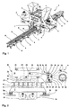
- a stone forming machine 1 is shown in a perspective view.
- the stone forming machine 1 comprises a movable main frame 2, which is mounted and guided on a static frame 32 and on the side two concrete bunkers 3, 4 are arranged.
- the first bunker 3 serves to accommodate the so-called core concrete and the second bunker 4 serves to accommodate the so-called facing concrete. Since the facing concrete is usually applied to the core concrete as a thin cover layer, the facing concrete bunker 4 has a smaller volume than the core concrete bunker 3.
- the block making machine 1 is fed by means of a conveying device 5 in cycles with underlay pallets 6.
- the sub-pallets 6 come to a centrally arranged in the stone forming machine 1 vibrating table 7 to a stop and serve to accommodate the moldings. 8
- a in Fig. 2 arranged in more detail filling car 9.
- the filling carriage 9 is filled with concrete from the bunkers 3, 4 via a filling device and moved via a drive in the direction of the stationary support pallet 6 or of the vibrating table 7. There, the concrete located in the filling car is introduced into the mold cavity of a lowered on the base pallet 6 stone mold.
- the concrete in the stone form can be compacted via a stamp and / or by movement of the vibrating table 7.
- the movement of the vibrating table 7 takes place via two unbalance vibrators 31 arranged below the vibrating table 7.
- the unbalance vibrators 31 have opposite directions of rotation, as indicated by the corresponding arrows.
- a filling carriage 9 with a vibrating grate 10 according to the invention which is in the in Fig. 1 shown stone forming machine 1 is used.
- the Scrissalrost 10 has a Scrissalrostschlitten 11 and a ScrissalrostgestShe 12 and is arranged centrally in the filling carriage 9. To move the Scrissalrosts 10 this is connected via a connecting rod 14 with a drive 13.
- the connecting rod 14 comprises a connecting rod 15, a rocker arm 16 and connected to the drive 13 drive rocker 17, which is designed in the form of an eccentric rocker.
- the connecting rod 15 is connected via a first articulated connection 18 with the Scierelrostschlitten 11, and via a second articulated connection 19 with the articulated rocker 16.
- the articulated rocker 16 is rotatably connected to a static bearing 21 by a third articulation 20.
- the static bearing 21 is part of the frame of the filling carriage.
- the rocker arm 16 is connected to the drive rocker 17.
- a hydraulic motor which can provide a high torque of 900 Nm in a small size.
- the Scierelrostschlitten 11 is guided horizontally in slide bushes designed as sliding guides 26 which are arranged on the frame of the filling carriage 9.
- a rotational movement DB generated by the drive 13 is converted into a horizontal movement HB of the Scierelrostschlittens 11, as is also indicated by the corresponding arrows.
- the connecting rod 15 and the rocker arm 16 three coupling points 23 for the second hinge connection 19.
- the connecting rod 15 at its end facing the drive 13 has an L-shaped tab 25, in the region of which the coupling points 23 of the second articulated connection 19 are arranged.
- the articulated rocker 16 has corresponding coupling points 23 for this purpose.
- the articulated rocker 16 has two coupling points 24 for the fourth articulated connection 22.
- the connecting rod 15 is coupled to the hinge link 16 at the middle coupling point 19.
- the drive rocker 17 is coupled at the lower coupling point 24 to the rocker arm 16.
- the horizontal lifting and force component of Scierelrostschlittens 11 are changed.
- the horizontal lifting component of the vibrating conveyor carriage 11 can be reduced by repositioning the connecting bolt of the second articulated connection 19 into the lowest coupling point 23. At the same time, this increases the horizontal force component.
- the said horizontal movement HB of the Scierelrostschlittens 11 causes the raw material 28 can be optimally and evenly distributed in the mold cavities of the lowered on the pad pallet 6 stone mold 27.
- the brick mold 27 has six mold cavities per row, but the vibrating grate 10 according to the invention is flexible adjustable to a plurality of brick molds 27 with variable width, length, depth and number of mold cavities.
- the Sc5.lrostgest briefly 12 can be solved by loosening the compounds 29 from Sc.lrostschlitten 11 and thus replaced, implemented or adjusted in height, which increases the variability and flexibility of Scrissalrosts 10 according to the invention again.
- the compounds 29 between Sc.lrostschlitten 11 and Sc.lrostgestShe 12 may be performed for example as screw or the like.
Landscapes
- Engineering & Computer Science (AREA)
- Mechanical Engineering (AREA)
- Manufacturing & Machinery (AREA)
- Ceramic Engineering (AREA)
- Chemical & Material Sciences (AREA)
- General Health & Medical Sciences (AREA)
- Physical Education & Sports Medicine (AREA)
- Health & Medical Sciences (AREA)
- Press-Shaping Or Shaping Using Conveyers (AREA)
- Revetment (AREA)
- On-Site Construction Work That Accompanies The Preparation And Application Of Concrete (AREA)
- Apparatuses For Generation Of Mechanical Vibrations (AREA)
- Combined Means For Separation Of Solids (AREA)
- Moulds, Cores, Or Mandrels (AREA)
- Devices For Post-Treatments, Processing, Supply, Discharge, And Other Processes (AREA)
Priority Applications (1)
| Application Number | Priority Date | Filing Date | Title |
|---|---|---|---|
| PL12718998T PL2707186T3 (pl) | 2011-05-13 | 2012-05-04 | Ruszt wstrząsany dla podajnika wsadu maszyny do formowania bloczków |
Applications Claiming Priority (2)
| Application Number | Priority Date | Filing Date | Title |
|---|---|---|---|
| DE102011050367A DE102011050367B4 (de) | 2011-05-13 | 2011-05-13 | Schüttelrost für einen Füllwagen einer Steinformmaschine |
| PCT/EP2012/058216 WO2012156212A1 (de) | 2011-05-13 | 2012-05-04 | Schüttelrost für einen füllwagen einer steinformmaschine |
Publications (2)
| Publication Number | Publication Date |
|---|---|
| EP2707186A1 EP2707186A1 (de) | 2014-03-19 |
| EP2707186B1 true EP2707186B1 (de) | 2016-10-12 |
Family
ID=46027976
Family Applications (1)
| Application Number | Title | Priority Date | Filing Date |
|---|---|---|---|
| EP12718998.3A Active EP2707186B1 (de) | 2011-05-13 | 2012-05-04 | Schüttelrost für einen füllwagen einer steinformmaschine |
Country Status (10)
| Country | Link |
|---|---|
| US (1) | US8899958B2 (pl) |
| EP (1) | EP2707186B1 (pl) |
| CN (1) | CN103732367B (pl) |
| BR (1) | BR112013029303B1 (pl) |
| DE (2) | DE202011110087U1 (pl) |
| DK (1) | DK2707186T3 (pl) |
| ES (1) | ES2606485T3 (pl) |
| PL (1) | PL2707186T3 (pl) |
| RU (1) | RU2554973C1 (pl) |
| WO (1) | WO2012156212A1 (pl) |
Families Citing this family (12)
| Publication number | Priority date | Publication date | Assignee | Title |
|---|---|---|---|---|
| CN104786362B (zh) * | 2015-04-16 | 2017-06-16 | 张历豪 | 一种建筑预制件的生产设备 |
| CN104760131B (zh) * | 2015-04-16 | 2017-02-01 | 广西宏发重工机械有限公司 | 一种用于砌块成型机的布料系统 |
| CN106938493A (zh) * | 2017-03-30 | 2017-07-11 | 福建群峰机械有限公司 | 一种砌块机的布料车总成 |
| CN108340619B (zh) * | 2018-02-08 | 2023-12-29 | 山西沁新能源集团股份有限公司 | 一种高效自动型煤液压装置 |
| CN109352800B (zh) * | 2018-08-28 | 2021-07-16 | 昆明理工大学 | 一种陶瓷颗粒增强金属基复合材料预制体成形方法及装置 |
| DE102018121741A1 (de) | 2018-09-06 | 2020-03-12 | Franz Carl Nüdling Basaltwerke GmbH + Co KG | Vorrichtung zur Herstellung von Betonsteinen |
| DE102019105867B4 (de) * | 2019-03-07 | 2025-12-24 | Masa GmbH | Füllvorrichtung für eine Steinformmaschine |
| DE102019114402B4 (de) * | 2019-05-29 | 2026-02-26 | Godelmann Gmbh & Co. Kg | Verfahren zum Herstellen eines Beton-Fertigbauteils |
| CN110744704B (zh) * | 2019-11-01 | 2021-02-26 | 吉林建筑科技学院 | 一种建筑水泥钢板节能制备装置 |
| CN110774435B (zh) * | 2019-11-07 | 2024-09-13 | 福建鸿益机械有限公司 | 一种分料装置 |
| CN111070398B (zh) * | 2019-12-31 | 2021-03-19 | 广东海源管业有限公司 | 一种精准混凝土试块制作方法及工装模具 |
| IL280802B2 (en) * | 2021-02-10 | 2023-05-01 | Ackerstein Ind Ltd | System and method for painting upper surfaces of bricks and concrete paving stones. |
Family Cites Families (38)
| Publication number | Priority date | Publication date | Assignee | Title |
|---|---|---|---|---|
| US1586804A (en) * | 1926-06-01 | heskett | ||
| US151492A (en) * | 1874-06-02 | Improvement in brick-machines | ||
| US70585A (en) * | 1867-11-05 | Stephen w | ||
| US171453A (en) * | 1875-12-21 | Improvement in brick-machines | ||
| US661008A (en) * | 1900-07-12 | 1900-10-30 | Confectioners Machinery And Mfg Company | Depositing-machine for confectionery. |
| US1336598A (en) * | 1918-09-11 | 1920-04-13 | Charles E Throop | Sheet-moving mechanism |
| US1424469A (en) * | 1921-04-02 | 1922-08-01 | Gillard William | Cement-tile-making machine |
| US1765064A (en) * | 1927-04-04 | 1930-06-17 | Charles M Eberling | Building-block machine |
| US1690422A (en) * | 1927-08-05 | 1928-11-06 | Multiplex Concrete Machinery C | Block machine |
| US1891790A (en) * | 1928-12-20 | 1932-12-20 | American Wilderman Porous Ebon | Spreading apparatus |
| US2314577A (en) * | 1941-07-29 | 1943-03-23 | W E Dunn Mfg Company | Cement block molding machine |
| US2308132A (en) * | 1942-01-16 | 1943-01-12 | Harry A Wellnitz | Concrete block forming machine |
| US2512163A (en) * | 1946-01-24 | 1950-06-20 | Nat Gypsum Co | Self-cleaning mixer gate |
| US2562541A (en) * | 1946-05-18 | 1951-07-31 | Flam John | Concrete block molding machine |
| US2514971A (en) * | 1946-10-18 | 1950-07-11 | Robert S Reed | Brick or block casting machine |
| US2464641A (en) * | 1947-05-16 | 1949-03-15 | Duncan G Grant | Block stripping and height control means |
| DE927560C (de) * | 1951-05-05 | 1955-05-12 | Schlosser & Co | Fuellkasten fuer Steinformmaschinen |
| US3184818A (en) * | 1953-10-19 | 1965-05-25 | Eugene E Crile | Automatic mix regulating devices for cement block molding machines |
| US2957222A (en) * | 1954-11-23 | 1960-10-25 | Zmania Leo | Apparatus for producing concrete blocks and the like |
| US2839810A (en) * | 1955-02-10 | 1958-06-24 | Bergen Machine & Tool Co Inc | Aggregate feed apparatus for concrete block machines |
| US3055075A (en) * | 1960-01-11 | 1962-09-25 | William F Stefanick | Block making machine |
| US2957221A (en) * | 1960-03-02 | 1960-10-25 | Zmania Leo | Concrete block forming apparatus |
| FR1261590A (fr) * | 1960-06-24 | 1961-05-19 | Brouiller & Cie | Dispositif de frittage pour machines à mouler les moellons à commande hydraulique |
| US3213511A (en) * | 1962-04-10 | 1965-10-26 | S & S Mfg Co | Cement block machine |
| US3504408A (en) * | 1965-01-09 | 1970-04-07 | William E Jones | Apparatus for molding interlocking concrete blocks |
| US3816052A (en) * | 1972-07-17 | 1974-06-11 | Package Machinery Co | Operating apparatus for the platens in a thermoforming machine |
| US3885900A (en) * | 1973-09-21 | 1975-05-27 | George E Kanta | Feed box cut-off gate |
| DE7600208U1 (de) * | 1976-01-07 | 1976-05-06 | Misch- Und Transport-Anlagen Gmbh, 5470 Andernach | Füllvorrichtung für Steinformmaschine |
| JPS5361618A (en) * | 1976-11-16 | 1978-06-02 | Chiyoda Giken Kogyo Kk | Apparatus for making concrete products |
| SU779780A1 (ru) * | 1978-12-26 | 1980-11-15 | Всесоюзный Научно-Исследовательский Институт Цементного Машиностроения | Колосникова решетка |
| US5807591A (en) * | 1994-07-28 | 1998-09-15 | Columbia Machine, Inc. | Method and apparatus for forming concrete products |
| RU2096176C1 (ru) * | 1996-08-06 | 1997-11-20 | Алексей Иванович Аленин | Устройство для изготовления полых изделий из термопластов |
| ITRE20010072A1 (it) * | 2001-07-05 | 2003-01-05 | Sacmi | Metodo per il caricamento degli stampi ceramici di formatura delle piastrelle, impianto per la sua attuazione, e piastrelle ottenute con det |
| JP2003127128A (ja) * | 2001-10-26 | 2003-05-08 | Kei:Kk | コンクリートブロック成型機用の材料撹拌装置 |
| EP1975507A1 (de) * | 2007-03-29 | 2008-10-01 | ThyssenKrupp Xervon Energy GmbH | Vorschubrost für Feuerungsanlagen |
| CN201124532Y (zh) * | 2007-11-16 | 2008-10-01 | 张鲁军 | 一种砖机定量布料机 |
| US8568129B2 (en) * | 2009-06-03 | 2013-10-29 | Keystone Retaining Wall Systems Llc | Floating cut-off bar for a mold box |
| US20100310695A1 (en) * | 2009-06-03 | 2010-12-09 | Keystone Retaining Wall Systems, Inc. | Floating cut-off bar and method of use thereof |
-
2011
- 2011-05-13 DE DE202011110087U patent/DE202011110087U1/de not_active Expired - Lifetime
- 2011-05-13 DE DE102011050367A patent/DE102011050367B4/de active Active
-
2012
- 2012-05-04 US US14/117,352 patent/US8899958B2/en active Active
- 2012-05-04 ES ES12718998.3T patent/ES2606485T3/es active Active
- 2012-05-04 BR BR112013029303-9A patent/BR112013029303B1/pt active IP Right Grant
- 2012-05-04 DK DK12718998.3T patent/DK2707186T3/en active
- 2012-05-04 CN CN201280034649.4A patent/CN103732367B/zh active Active
- 2012-05-04 WO PCT/EP2012/058216 patent/WO2012156212A1/de not_active Ceased
- 2012-05-04 PL PL12718998T patent/PL2707186T3/pl unknown
- 2012-05-04 EP EP12718998.3A patent/EP2707186B1/de active Active
- 2012-05-04 RU RU2013154018/03A patent/RU2554973C1/ru active
Also Published As
| Publication number | Publication date |
|---|---|
| US20140147544A1 (en) | 2014-05-29 |
| PL2707186T3 (pl) | 2017-06-30 |
| CN103732367B (zh) | 2016-08-24 |
| RU2013154018A (ru) | 2015-06-20 |
| ES2606485T3 (es) | 2017-03-24 |
| BR112013029303A2 (pt) | 2017-06-20 |
| CN103732367A (zh) | 2014-04-16 |
| DE102011050367A1 (de) | 2012-11-15 |
| WO2012156212A1 (de) | 2012-11-22 |
| EP2707186A1 (de) | 2014-03-19 |
| BR112013029303B1 (pt) | 2020-11-17 |
| US8899958B2 (en) | 2014-12-02 |
| RU2554973C1 (ru) | 2015-07-10 |
| DE202011110087U1 (de) | 2012-11-12 |
| DE102011050367B4 (de) | 2012-12-20 |
| DK2707186T3 (en) | 2017-01-23 |
Similar Documents
| Publication | Publication Date | Title |
|---|---|---|
| EP2707186B1 (de) | Schüttelrost für einen füllwagen einer steinformmaschine | |
| EP4076881B1 (de) | Vorrichtung zur herstellung von betonsteinen | |
| EP2173542B1 (de) | Befüllungseinrichtung zum befüllen von formwerkzeugen mit schüttfähigem formmaterial | |
| DE69508540T2 (de) | Formmaschine | |
| EP2258488A2 (de) | Antriebsanordnung für einen länglichen Schwingkörper | |
| DE68910248T2 (de) | Elektrische pulver-giessvorrichtung. | |
| EP2839950A2 (de) | Presse zur Herstellung von Presslingen aus pulverförmigem Material | |
| EP2001432A1 (de) | Vorrichtung zum befüllen von zumindest einer dosierkammer | |
| EP1663605A1 (de) | Einspritzeinheit sowie verfahren für die einstellung der einspritzeinheit | |
| WO1993004831A1 (de) | Vertikalpresse und verfahren zu deren betrieb | |
| EP0326870A1 (de) | Verfahren und Vorrichtung zur Durchführung des Verfahrens zum Verdichten von Giessereiformsand | |
| DE69524078T2 (de) | Verfahren und vorrichtung zum herstellen von zementprodukten | |
| DE102017007785A1 (de) | Anordnung und Verfahren zur Erzeugung einer 3D-Struktur | |
| DE1507959C3 (de) | Maschine zur Erzeugung von Form lingen aus plastischer Masse | |
| DE19903417B4 (de) | Verfahren zum Befüllen einer Hydraulikpresse mit Pulvern | |
| EP2697141B1 (de) | Transportvorrichtung | |
| DD241711A5 (de) | Verfahren und vorrichtung zum giessen von betonprodukten | |
| DE102004009382B3 (de) | Verfahren und Vorrichtung zum Herstellen von Betonsteinen | |
| DE102007012593B4 (de) | Vorrichtung zum Beschicken von Formen zum Herstellen von Betonplatten oder Betonsteinen | |
| DE102004046147A1 (de) | Verfahren zum Herstellen von Betonsteinen | |
| DE102021128776A1 (de) | Rüttelvorrichtung und Verfahren zur Bodenverdichtung | |
| DE2059760C2 (de) | Gleitfertiger zum Herstellen von Formkörpern aus Beton oder ähnlichem Material | |
| DE2913305A1 (de) | Vorrichtung zum verdichten von formkoerpern aus beton o.dgl. plastischen massen | |
| DE2548956C3 (de) | Verfahren und Formmaschine zur Herstellung einer Gießereiform | |
| DE102015102212A1 (de) | Pressvorrichtung zur Herstellung von Steinen |
Legal Events
| Date | Code | Title | Description |
|---|---|---|---|
| PUAI | Public reference made under article 153(3) epc to a published international application that has entered the european phase |
Free format text: ORIGINAL CODE: 0009012 |
|
| 17P | Request for examination filed |
Effective date: 20131108 |
|
| AK | Designated contracting states |
Kind code of ref document: A1 Designated state(s): AL AT BE BG CH CY CZ DE DK EE ES FI FR GB GR HR HU IE IS IT LI LT LU LV MC MK MT NL NO PL PT RO RS SE SI SK SM TR |
|
| DAX | Request for extension of the european patent (deleted) | ||
| 17Q | First examination report despatched |
Effective date: 20141103 |
|
| GRAP | Despatch of communication of intention to grant a patent |
Free format text: ORIGINAL CODE: EPIDOSNIGR1 |
|
| RIC1 | Information provided on ipc code assigned before grant |
Ipc: B28B 13/02 20060101AFI20160517BHEP |
|
| INTG | Intention to grant announced |
Effective date: 20160606 |
|
| GRAS | Grant fee paid |
Free format text: ORIGINAL CODE: EPIDOSNIGR3 |
|
| GRAA | (expected) grant |
Free format text: ORIGINAL CODE: 0009210 |
|
| AK | Designated contracting states |
Kind code of ref document: B1 Designated state(s): AL AT BE BG CH CY CZ DE DK EE ES FI FR GB GR HR HU IE IS IT LI LT LU LV MC MK MT NL NO PL PT RO RS SE SI SK SM TR |
|
| REG | Reference to a national code |
Ref country code: GB Ref legal event code: FG4D Free format text: NOT ENGLISH |
|
| REG | Reference to a national code |
Ref country code: CH Ref legal event code: EP |
|
| REG | Reference to a national code |
Ref country code: AT Ref legal event code: REF Ref document number: 836079 Country of ref document: AT Kind code of ref document: T Effective date: 20161015 |
|
| REG | Reference to a national code |
Ref country code: IE Ref legal event code: FG4D Free format text: LANGUAGE OF EP DOCUMENT: GERMAN |
|
| REG | Reference to a national code |
Ref country code: DE Ref legal event code: R096 Ref document number: 502012008501 Country of ref document: DE |
|
| REG | Reference to a national code |
Ref country code: DE Ref legal event code: R108 Ref document number: 502012008501 Country of ref document: DE |
|
| RBV | Designated contracting states (corrected) |
Designated state(s): AL AT BE BG CH CY CZ DK EE ES FI FR GB GR HR HU IE IS IT LI LT LU LV MC MK MT NL NO PL PT RO RS SE SI SK SM TR |
|
| REG | Reference to a national code |
Ref country code: NL Ref legal event code: FP |
|
| REG | Reference to a national code |
Ref country code: DK Ref legal event code: T3 Effective date: 20170116 |
|
| REG | Reference to a national code |
Ref country code: DE Ref legal event code: R107 Ref document number: 502012008501 Country of ref document: DE |
|
| REG | Reference to a national code |
Ref country code: LT Ref legal event code: MG4D |
|
| PG25 | Lapsed in a contracting state [announced via postgrant information from national office to epo] |
Ref country code: LV Free format text: LAPSE BECAUSE OF FAILURE TO SUBMIT A TRANSLATION OF THE DESCRIPTION OR TO PAY THE FEE WITHIN THE PRESCRIBED TIME-LIMIT Effective date: 20161012 |
|
| PG25 | Lapsed in a contracting state [announced via postgrant information from national office to epo] |
Ref country code: NO Free format text: LAPSE BECAUSE OF FAILURE TO SUBMIT A TRANSLATION OF THE DESCRIPTION OR TO PAY THE FEE WITHIN THE PRESCRIBED TIME-LIMIT Effective date: 20170112 Ref country code: GR Free format text: LAPSE BECAUSE OF FAILURE TO SUBMIT A TRANSLATION OF THE DESCRIPTION OR TO PAY THE FEE WITHIN THE PRESCRIBED TIME-LIMIT Effective date: 20170113 Ref country code: SE Free format text: LAPSE BECAUSE OF FAILURE TO SUBMIT A TRANSLATION OF THE DESCRIPTION OR TO PAY THE FEE WITHIN THE PRESCRIBED TIME-LIMIT Effective date: 20161012 Ref country code: LT Free format text: LAPSE BECAUSE OF FAILURE TO SUBMIT A TRANSLATION OF THE DESCRIPTION OR TO PAY THE FEE WITHIN THE PRESCRIBED TIME-LIMIT Effective date: 20161012 |
|
| REG | Reference to a national code |
Ref country code: FR Ref legal event code: PLFP Year of fee payment: 6 |
|
| PG25 | Lapsed in a contracting state [announced via postgrant information from national office to epo] |
Ref country code: HR Free format text: LAPSE BECAUSE OF FAILURE TO SUBMIT A TRANSLATION OF THE DESCRIPTION OR TO PAY THE FEE WITHIN THE PRESCRIBED TIME-LIMIT Effective date: 20161012 Ref country code: FI Free format text: LAPSE BECAUSE OF FAILURE TO SUBMIT A TRANSLATION OF THE DESCRIPTION OR TO PAY THE FEE WITHIN THE PRESCRIBED TIME-LIMIT Effective date: 20161012 Ref country code: PT Free format text: LAPSE BECAUSE OF FAILURE TO SUBMIT A TRANSLATION OF THE DESCRIPTION OR TO PAY THE FEE WITHIN THE PRESCRIBED TIME-LIMIT Effective date: 20170213 Ref country code: RS Free format text: LAPSE BECAUSE OF FAILURE TO SUBMIT A TRANSLATION OF THE DESCRIPTION OR TO PAY THE FEE WITHIN THE PRESCRIBED TIME-LIMIT Effective date: 20161012 Ref country code: IS Free format text: LAPSE BECAUSE OF FAILURE TO SUBMIT A TRANSLATION OF THE DESCRIPTION OR TO PAY THE FEE WITHIN THE PRESCRIBED TIME-LIMIT Effective date: 20170212 |
|
| PG25 | Lapsed in a contracting state [announced via postgrant information from national office to epo] |
Ref country code: EE Free format text: LAPSE BECAUSE OF FAILURE TO SUBMIT A TRANSLATION OF THE DESCRIPTION OR TO PAY THE FEE WITHIN THE PRESCRIBED TIME-LIMIT Effective date: 20161012 Ref country code: CZ Free format text: LAPSE BECAUSE OF FAILURE TO SUBMIT A TRANSLATION OF THE DESCRIPTION OR TO PAY THE FEE WITHIN THE PRESCRIBED TIME-LIMIT Effective date: 20161012 Ref country code: RO Free format text: LAPSE BECAUSE OF FAILURE TO SUBMIT A TRANSLATION OF THE DESCRIPTION OR TO PAY THE FEE WITHIN THE PRESCRIBED TIME-LIMIT Effective date: 20161012 Ref country code: SK Free format text: LAPSE BECAUSE OF FAILURE TO SUBMIT A TRANSLATION OF THE DESCRIPTION OR TO PAY THE FEE WITHIN THE PRESCRIBED TIME-LIMIT Effective date: 20161012 |
|
| PLBE | No opposition filed within time limit |
Free format text: ORIGINAL CODE: 0009261 |
|
| STAA | Information on the status of an ep patent application or granted ep patent |
Free format text: STATUS: NO OPPOSITION FILED WITHIN TIME LIMIT |
|
| PG25 | Lapsed in a contracting state [announced via postgrant information from national office to epo] |
Ref country code: SM Free format text: LAPSE BECAUSE OF FAILURE TO SUBMIT A TRANSLATION OF THE DESCRIPTION OR TO PAY THE FEE WITHIN THE PRESCRIBED TIME-LIMIT Effective date: 20161012 Ref country code: BG Free format text: LAPSE BECAUSE OF FAILURE TO SUBMIT A TRANSLATION OF THE DESCRIPTION OR TO PAY THE FEE WITHIN THE PRESCRIBED TIME-LIMIT Effective date: 20170112 Ref country code: LU Free format text: LAPSE BECAUSE OF NON-PAYMENT OF DUE FEES Effective date: 20170531 Ref country code: IT Free format text: LAPSE BECAUSE OF FAILURE TO SUBMIT A TRANSLATION OF THE DESCRIPTION OR TO PAY THE FEE WITHIN THE PRESCRIBED TIME-LIMIT Effective date: 20161012 |
|
| 26N | No opposition filed |
Effective date: 20170713 |
|
| PG25 | Lapsed in a contracting state [announced via postgrant information from national office to epo] |
Ref country code: SI Free format text: LAPSE BECAUSE OF FAILURE TO SUBMIT A TRANSLATION OF THE DESCRIPTION OR TO PAY THE FEE WITHIN THE PRESCRIBED TIME-LIMIT Effective date: 20161012 |
|
| REG | Reference to a national code |
Ref country code: CH Ref legal event code: PL |
|
| PG25 | Lapsed in a contracting state [announced via postgrant information from national office to epo] |
Ref country code: MC Free format text: LAPSE BECAUSE OF FAILURE TO SUBMIT A TRANSLATION OF THE DESCRIPTION OR TO PAY THE FEE WITHIN THE PRESCRIBED TIME-LIMIT Effective date: 20161012 |
|
| REG | Reference to a national code |
Ref country code: IE Ref legal event code: MM4A |
|
| PG25 | Lapsed in a contracting state [announced via postgrant information from national office to epo] |
Ref country code: CH Free format text: LAPSE BECAUSE OF NON-PAYMENT OF DUE FEES Effective date: 20170531 Ref country code: LI Free format text: LAPSE BECAUSE OF NON-PAYMENT OF DUE FEES Effective date: 20170531 |
|
| PG25 | Lapsed in a contracting state [announced via postgrant information from national office to epo] |
Ref country code: LU Free format text: LAPSE BECAUSE OF NON-PAYMENT OF DUE FEES Effective date: 20170504 |
|
| PG25 | Lapsed in a contracting state [announced via postgrant information from national office to epo] |
Ref country code: IE Free format text: LAPSE BECAUSE OF NON-PAYMENT OF DUE FEES Effective date: 20170504 |
|
| REG | Reference to a national code |
Ref country code: FR Ref legal event code: PLFP Year of fee payment: 7 |
|
| REG | Reference to a national code |
Ref country code: AT Ref legal event code: MM01 Ref document number: 836079 Country of ref document: AT Kind code of ref document: T Effective date: 20170504 |
|
| PG25 | Lapsed in a contracting state [announced via postgrant information from national office to epo] |
Ref country code: AT Free format text: LAPSE BECAUSE OF NON-PAYMENT OF DUE FEES Effective date: 20170504 |
|
| PG25 | Lapsed in a contracting state [announced via postgrant information from national office to epo] |
Ref country code: MT Free format text: LAPSE BECAUSE OF FAILURE TO SUBMIT A TRANSLATION OF THE DESCRIPTION OR TO PAY THE FEE WITHIN THE PRESCRIBED TIME-LIMIT Effective date: 20161012 |
|
| PG25 | Lapsed in a contracting state [announced via postgrant information from national office to epo] |
Ref country code: HU Free format text: LAPSE BECAUSE OF FAILURE TO SUBMIT A TRANSLATION OF THE DESCRIPTION OR TO PAY THE FEE WITHIN THE PRESCRIBED TIME-LIMIT; INVALID AB INITIO Effective date: 20120504 |
|
| PG25 | Lapsed in a contracting state [announced via postgrant information from national office to epo] |
Ref country code: CY Free format text: LAPSE BECAUSE OF NON-PAYMENT OF DUE FEES Effective date: 20161012 |
|
| PG25 | Lapsed in a contracting state [announced via postgrant information from national office to epo] |
Ref country code: MK Free format text: LAPSE BECAUSE OF FAILURE TO SUBMIT A TRANSLATION OF THE DESCRIPTION OR TO PAY THE FEE WITHIN THE PRESCRIBED TIME-LIMIT Effective date: 20161012 |
|
| PG25 | Lapsed in a contracting state [announced via postgrant information from national office to epo] |
Ref country code: TR Free format text: LAPSE BECAUSE OF FAILURE TO SUBMIT A TRANSLATION OF THE DESCRIPTION OR TO PAY THE FEE WITHIN THE PRESCRIBED TIME-LIMIT Effective date: 20161012 |
|
| PG25 | Lapsed in a contracting state [announced via postgrant information from national office to epo] |
Ref country code: AL Free format text: LAPSE BECAUSE OF FAILURE TO SUBMIT A TRANSLATION OF THE DESCRIPTION OR TO PAY THE FEE WITHIN THE PRESCRIBED TIME-LIMIT Effective date: 20161012 |
|
| PGFP | Annual fee paid to national office [announced via postgrant information from national office to epo] |
Ref country code: NL Payment date: 20250522 Year of fee payment: 14 |
|
| PGFP | Annual fee paid to national office [announced via postgrant information from national office to epo] |
Ref country code: PL Payment date: 20250417 Year of fee payment: 14 |
|
| PGFP | Annual fee paid to national office [announced via postgrant information from national office to epo] |
Ref country code: GB Payment date: 20250522 Year of fee payment: 14 Ref country code: ES Payment date: 20250616 Year of fee payment: 14 Ref country code: DK Payment date: 20250521 Year of fee payment: 14 |
|
| PGFP | Annual fee paid to national office [announced via postgrant information from national office to epo] |
Ref country code: BE Payment date: 20250520 Year of fee payment: 14 |
|
| PGFP | Annual fee paid to national office [announced via postgrant information from national office to epo] |
Ref country code: FR Payment date: 20250523 Year of fee payment: 14 |