EP2700545B1 - Procédé de fonctionnement d'un système de commande d'une moto - Google Patents
Procédé de fonctionnement d'un système de commande d'une moto Download PDFInfo
- Publication number
- EP2700545B1 EP2700545B1 EP13190738.8A EP13190738A EP2700545B1 EP 2700545 B1 EP2700545 B1 EP 2700545B1 EP 13190738 A EP13190738 A EP 13190738A EP 2700545 B1 EP2700545 B1 EP 2700545B1
- Authority
- EP
- European Patent Office
- Prior art keywords
- locking
- locking member
- steering lock
- actuating element
- motorcycle
- Prior art date
- Legal status (The legal status is an assumption and is not a legal conclusion. Google has not performed a legal analysis and makes no representation as to the accuracy of the status listed.)
- Active
Links
- 238000000034 method Methods 0.000 title claims description 62
- 230000008569 process Effects 0.000 claims description 47
- 230000005540 biological transmission Effects 0.000 claims description 39
- 230000009471 action Effects 0.000 claims description 38
- 230000004913 activation Effects 0.000 claims description 25
- 230000006854 communication Effects 0.000 claims description 11
- 238000004891 communication Methods 0.000 claims description 11
- 230000001960 triggered effect Effects 0.000 claims description 8
- 238000012546 transfer Methods 0.000 claims description 6
- 230000003213 activating effect Effects 0.000 description 3
- 230000007175 bidirectional communication Effects 0.000 description 2
- 230000001419 dependent effect Effects 0.000 description 2
- 238000011161 development Methods 0.000 description 2
- 230000018109 developmental process Effects 0.000 description 2
- 238000013459 approach Methods 0.000 description 1
- 238000013475 authorization Methods 0.000 description 1
- 230000008878 coupling Effects 0.000 description 1
- 238000010168 coupling process Methods 0.000 description 1
- 238000005859 coupling reaction Methods 0.000 description 1
- 238000006073 displacement reaction Methods 0.000 description 1
- 210000003746 feather Anatomy 0.000 description 1
- 230000001939 inductive effect Effects 0.000 description 1
- 230000000977 initiatory effect Effects 0.000 description 1
- 238000004519 manufacturing process Methods 0.000 description 1
- 230000003287 optical effect Effects 0.000 description 1
- 238000003825 pressing Methods 0.000 description 1
- 230000002035 prolonged effect Effects 0.000 description 1
- 230000007420 reactivation Effects 0.000 description 1
Images


Classifications
-
- B—PERFORMING OPERATIONS; TRANSPORTING
- B60—VEHICLES IN GENERAL
- B60R—VEHICLES, VEHICLE FITTINGS, OR VEHICLE PARTS, NOT OTHERWISE PROVIDED FOR
- B60R25/00—Fittings or systems for preventing or indicating unauthorised use or theft of vehicles
- B60R25/01—Fittings or systems for preventing or indicating unauthorised use or theft of vehicles operating on vehicle systems or fittings, e.g. on doors, seats or windscreens
- B60R25/02—Fittings or systems for preventing or indicating unauthorised use or theft of vehicles operating on vehicle systems or fittings, e.g. on doors, seats or windscreens operating on the steering mechanism
- B60R25/021—Fittings or systems for preventing or indicating unauthorised use or theft of vehicles operating on vehicle systems or fittings, e.g. on doors, seats or windscreens operating on the steering mechanism restraining movement of the steering column or steering wheel hub, e.g. restraining means controlled by ignition switch
- B60R25/02147—Fittings or systems for preventing or indicating unauthorised use or theft of vehicles operating on vehicle systems or fittings, e.g. on doors, seats or windscreens operating on the steering mechanism restraining movement of the steering column or steering wheel hub, e.g. restraining means controlled by ignition switch comprising a locking member having other than linear, axial or radial motion, e.g. rotatable; Steering column locking using balls, rollers or the like
-
- B—PERFORMING OPERATIONS; TRANSPORTING
- B60—VEHICLES IN GENERAL
- B60R—VEHICLES, VEHICLE FITTINGS, OR VEHICLE PARTS, NOT OTHERWISE PROVIDED FOR
- B60R25/00—Fittings or systems for preventing or indicating unauthorised use or theft of vehicles
- B60R25/01—Fittings or systems for preventing or indicating unauthorised use or theft of vehicles operating on vehicle systems or fittings, e.g. on doors, seats or windscreens
- B60R25/02—Fittings or systems for preventing or indicating unauthorised use or theft of vehicles operating on vehicle systems or fittings, e.g. on doors, seats or windscreens operating on the steering mechanism
- B60R25/021—Fittings or systems for preventing or indicating unauthorised use or theft of vehicles operating on vehicle systems or fittings, e.g. on doors, seats or windscreens operating on the steering mechanism restraining movement of the steering column or steering wheel hub, e.g. restraining means controlled by ignition switch
- B60R25/0215—Fittings or systems for preventing or indicating unauthorised use or theft of vehicles operating on vehicle systems or fittings, e.g. on doors, seats or windscreens operating on the steering mechanism restraining movement of the steering column or steering wheel hub, e.g. restraining means controlled by ignition switch using electric means, e.g. electric motors or solenoids
- B60R25/02153—Fittings or systems for preventing or indicating unauthorised use or theft of vehicles operating on vehicle systems or fittings, e.g. on doors, seats or windscreens operating on the steering mechanism restraining movement of the steering column or steering wheel hub, e.g. restraining means controlled by ignition switch using electric means, e.g. electric motors or solenoids comprising a locking member radially and linearly moved towards the steering column
-
- B—PERFORMING OPERATIONS; TRANSPORTING
- B60—VEHICLES IN GENERAL
- B60R—VEHICLES, VEHICLE FITTINGS, OR VEHICLE PARTS, NOT OTHERWISE PROVIDED FOR
- B60R25/00—Fittings or systems for preventing or indicating unauthorised use or theft of vehicles
- B60R25/01—Fittings or systems for preventing or indicating unauthorised use or theft of vehicles operating on vehicle systems or fittings, e.g. on doors, seats or windscreens
- B60R25/04—Fittings or systems for preventing or indicating unauthorised use or theft of vehicles operating on vehicle systems or fittings, e.g. on doors, seats or windscreens operating on the propulsion system, e.g. engine or drive motor
-
- B—PERFORMING OPERATIONS; TRANSPORTING
- B60—VEHICLES IN GENERAL
- B60R—VEHICLES, VEHICLE FITTINGS, OR VEHICLE PARTS, NOT OTHERWISE PROVIDED FOR
- B60R25/00—Fittings or systems for preventing or indicating unauthorised use or theft of vehicles
- B60R25/20—Means to switch the anti-theft system on or off
- B60R25/2063—Ignition switch geometry
-
- B—PERFORMING OPERATIONS; TRANSPORTING
- B60—VEHICLES IN GENERAL
- B60R—VEHICLES, VEHICLE FITTINGS, OR VEHICLE PARTS, NOT OTHERWISE PROVIDED FOR
- B60R25/00—Fittings or systems for preventing or indicating unauthorised use or theft of vehicles
- B60R25/20—Means to switch the anti-theft system on or off
- B60R25/24—Means to switch the anti-theft system on or off using electronic identifiers containing a code not memorised by the user
- B60R25/243—Means to switch the anti-theft system on or off using electronic identifiers containing a code not memorised by the user with more than one way to gain access
-
- B—PERFORMING OPERATIONS; TRANSPORTING
- B60—VEHICLES IN GENERAL
- B60R—VEHICLES, VEHICLE FITTINGS, OR VEHICLE PARTS, NOT OTHERWISE PROVIDED FOR
- B60R2325/00—Indexing scheme relating to vehicle anti-theft devices
- B60R2325/30—Vehicles applying the vehicle anti-theft devices
- B60R2325/306—Motorcycles
-
- Y—GENERAL TAGGING OF NEW TECHNOLOGICAL DEVELOPMENTS; GENERAL TAGGING OF CROSS-SECTIONAL TECHNOLOGIES SPANNING OVER SEVERAL SECTIONS OF THE IPC; TECHNICAL SUBJECTS COVERED BY FORMER USPC CROSS-REFERENCE ART COLLECTIONS [XRACs] AND DIGESTS
- Y10—TECHNICAL SUBJECTS COVERED BY FORMER USPC
- Y10T—TECHNICAL SUBJECTS COVERED BY FORMER US CLASSIFICATION
- Y10T70/00—Locks
- Y10T70/50—Special application
- Y10T70/5889—For automotive vehicles
- Y10T70/5956—Steering mechanism with switch
Definitions
- the invention relates to a method for operating a control system of a motorcycle for transferring an electromechanical steering lock from an unlocked position to a locked position and vice versa, with an ignition system for engine start of the motorcycle, which is controlled by the control system, an authentication in which an ID transmitter with the control system is in data communication, wherein after a positive authentication in an action process, the steering lock is brought into the respective position.
- a Authentication is started by sending a request signal from the motorcycle to the ID transmitter. If the ID transmitter identified as valid, that is, if the authentication is positive, that is, the electronic code of the ID transmitter matches the motorcycle-side code, the steering lock, in particular the electromechanical immobilizer is disabled. For some applications, it has been shown that, despite a positive authentication, a unlocking or locking process that can not be influenced directly by the user is not desired.
- An example of this is that, for example, when the motorcycle is switched off and the motorcyclist has dismounted, it may be desirable for the motorcycle to remain in an unlatched condition, for example because it is still several meters into the final parking position, especially into the garage shut off motor to be moved by the user.
- the document US5343077 discloses a system for controlling a steering lock with a locking member for a motor vehicle.
- the authentication of a user is done by an ID transmitter, wherein the user can operate the steering lock via an actuator.
- the method is provided with a first actuating element which is in signal communication with the control system and is accessible to a user, and the action process starts only after the positive authentication via a conscious activation of the first actuating element downstream of the authentication.
- the authentication can be started both unconsciously and by a conscious activation via the first actuator.
- bidirectional communication can take place in optical, inductive or capacitive ways or in a further alternative by radio transmission.
- the user After a positive authentication has been established, the user now has to start the actual action process, in particular the locking process or the unlocking process, by deliberately activating the first actuating element. If the user does not activate the actuator after a positive authentication process, the steering lock remains in its current position. That is, when the motor of the motorcycle has been turned off and there is no separate activation of the operating member by the user, the steering lock of the motorcycle remains in the unlocked position. According to this example, it should be added that while the motor of the motorcycle is on, there is always a process of authentication taking place in parallel at defined time intervals.
- a re-intentional activation of a second actuating element after the action process, in which the steering lock was brought into the unlocked position initiated a provision process in which energy of the ignition system of the motorcycle is provided, in particular via a renewed Activation of a third actuator, the engine start process is activated.
- the user can trigger the engine starting operation by actuating the respective actuating element twice.
- the control system checks during the action process an actual position of the steering unit with a desired position, wherein if the actual position corresponds to the desired position, the steering lock is brought from the unlocked position into the locking position. If the actual position is not equal to the desired position, the action process, in particular the locking process is aborted.
- the user receives a cancellation of the action process feedback on a malposition of the steering unit.
- the feedback can be done for example via a display on the steering unit. Also a feedback on the acoustic way is conceivable. If the handlebar of the handlebar unit is not in a defined, hammered handlebar position, there is thus no transfer of Steering lock from the unlocked position to the locked position. This check can be detected, for example, via push-button elements, sensors, etc., which are in data communication with the control system.
- an engine shutdown is triggered during engine operation via a deliberate activation of a fourth actuating element, wherein the control system of the ignition system interrupts the provision of energy.
- the engine shutdown is triggered only under defined motorcycle condition conditions, which are checked by the control system.
- one possible condition of the condition may be that the motorcycle must have a speed of 0 km / h, which means that it is stationary.
- the on-board electronics shutdown takes place in which, for example, the electronics of the display is turned off.
- the motorcycle is now in such a condition that the engine is switched off and only a "residual electronics" is powered, which among other things provides for the still active authentication or power the steering device with energy.
- the steering lock of the motorcycle is still in its unlocked position. The user can now bring the steering lock on the action process in the locked position by further activation of the first or the second actuating element.
- the first, the second and the fourth actuating element form a common central actuating element, which is arranged on the steering unit of the motorcycle freely accessible to the user.
- the aforementioned actuators may be configured as buttons, switches, proximity or touch switches, etc.
- the operation times of the central operating member for activating the action process and the provisioning operation may differ.
- the operating times of the action process and the on-board electronics shutdown can be different. This means that, for example, over a long operation of the central actuating element of the action process can be triggered. About a short operation of the central actuator, the deployment process or the on-board electronics shutdown can take place.
- the object is further achieved by an arrangement for controlling a steering lock with a locking member of a functionally essential component, in particular a steering column of a motorcycle, with a gear that is in mechanical engagement with the locking member, wherein the locking member in an action process between a locking position and an unlocked position is movable, with an authentication process in which an ID transmitter with a control system is in data communication, wherein after a positive authentication in the action process, the steering lock can be brought into the respective position in which engages in the locking position, the locking member in the functionally essential component and in the unlocked position, the locking member is released from the functionally essential component, wherein an accessible for a user operating element is provided, whereby a conscious activation of the actuating element the action starts.
- the control system with the steering lock is so in data communication that the action process is triggered only via a conscious, after the positive authentication downstream activation of the actuator.
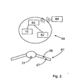
- FIG. 1 represents purely schematically, in a simplified representation of the inventive method for operating a control system 63 of a motorcycle for transferring an electromechanical steering lock 10 from an unlocked position 2 in a locking position 1, which in the FIGS. 5 to 12 are shown.
- FIG. 1 starts from an off motor of the motorcycle 60 (according to FIG. 2 ). If the potential user (motorcyclist) approaches the motorcycle 60 with an ID transmitter 64, an authentication 70 "automatically" starts at a defined distance from the motorcycle 60 and checks to what extent the code contained in the ID transmitter 64 corresponds to the code on the motorcycle side equivalent. The process of authentication 70 may be unconsciously triggered, for example, by moving the motorcycle stand, contacting the motorcycle seat, etc.
- the ID transmitter 64 is in communication with a control system 63 of the motorcycle 60.
- the control system 63 is further in signal communication with an electromechanical steering lock 10 and an ignition system 62 for starting the engine of the motorcycle 60.
- an activation operation of an actuating element 31, which is in signal communication with the control system 63, can be followed by an action process 71a, 71b, which is shown in FIG FIG. 3 and FIG. 4 is shown schematically in the flowchart, are triggered.
- the action process 71a, 71b the steering lock 10 is brought from its unlocked position 2 in a locking position 1 or vice versa, which in particular in the FIGS. 7 to 12 is shown.
- the actuating element 31 is arranged on the steering unit 61 of the motorcycle 60 (see FIG. 2 ). The user has to unlock the motorcycle 60 - after the positive authentication 70 - consciously activate the actuator 31, so that the steering lock 10 is driven accordingly.
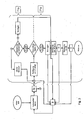
- the action process 71 a for unlocking the steering lock 10 is triggered by a prolonged actuation of the actuating element 31.
- FIG. 3 first checks the control system 63, to what extent the steering lock 10 is in the unlocked position 2 or in the locked position 1. If the steering lock 10 is in a locking position 2, an unlocking 71a of the steering lock 10 takes place.
- a provisioning process 72 is initiated in which energy of the ignition system 62 is made available. Compared to the operation time for initiating the steering lock unlocking action indicated at 71a, the actuation period for activating the provisioning operation 72 is shorter. Via a re-activation of the engine start switch 66 according to FIG. 2 the engine starting operation 73 is activated.
- the operation of authentication 70, during the action process 71a, 71b, the provisioning operation 72, the engine starting operation 73, and while the engine of the motorcycle 60 is in the ON state is repeatedly performed.
- the control system 63 changes the position of the steering lock 10 during the action 71 a, 71 b depending on the current position of the steering lock 10. This means that upon activation of the actuating element 31 to trigger an action process 71 a, 71 b, the control system 63 first checks which position 1, 2, the steering lock 10 currently has. Is the steering lock 10 in a locked position 1 is unlocked, the steering lock 10 is in the unlocked position 2 is locked. The action process 71b of the locking takes place in such a way that during the action procedure 71b the control system 63 checks an actual position of the steering unit 61 with a desired position. If the actual position corresponds to the desired position, the steering lock 10 is brought from the unlocked position 2 in the locking position 1.
- the action process 71b is aborted and the user receives information or a feedback that a misalignment of the steering unit 61 is present (see FIG. 3 ).
- a lock can thus take place only when the steering unit 61 is taken in a defined position.
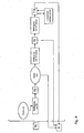
- FIG. 4 illustrates the control system 63, the authentication 70 during the engine shutdown 75, during the on-board electronics shutdown 76 and the action process 71 b for locking the steering lock 10.
- the control system 63 may switch to a sleep mode 77, if a corresponding activation of the respective actuating element omitted. If the method is in idle mode 77, there is no need for a constantly repeated authentication process.
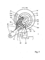
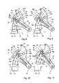
- FIGS. 7 to 12 show a possible embodiment of a steering lock 10, which is controlled via the described method.
- the steering lock 10 has a locking member 13 which can block a functionally essential component 40, here a steering column 40 of the motorcycle 60.
- the steering lock 10 has a gear 20 which is in mechanical coupling with the locking member 13.
- the locking member 13 In the FIGS. 7 and 8th is the locking member 13 in a locking position 1.
- the gear 20 about the gear 20, the steering lock 10, in particular the locking member 13 from the locking position 1 in an unlocked position 2 movable, in FIG. 11 is shown.
- the locking position 1 the locking member 13 protrudes with its free end into a groove 41 of the steering column 40, whereby the steering column 40 is locked.
- the locking member 13 is in the unlocked position 2 detached from the steering column 40th
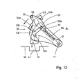
- the transmission 20 has a transmission member 21, which is designed as a drive wheel and is rotatably mounted on an axis 24.
- the transmission member 21 is connected via an electronic motor 25, which in FIG. 5 and FIG. 6 is shown, driven.
- the electronic motor 25 has a pinion which engages a toothed region 26 of the transmission member 21.
- the axis of rotation 24 of the transmission member 21 and the axis of rotation of the pinion, not shown, are parallel to each other, whereby a spur gear between the toothed portion 26 of the transmission member 21 and the pinion of the electric motor 25 is present.
- an accessible to a user actuator unit 30 is provided which is in a normal operation with the transmission 20 in signal communication.
- the transmission 20 is electronically controlled, whereby the locking member 13 is brought into its respective position 1, 2, which in the following with reference to FIGS. 8 to 12 is explained.
- the actuator 30 is mechanically decoupled from the transmission 20.
- the actuator unit 30 can be mechanically coupled to the transmission 20, in which an emergency key 33 in a receiving body 32, in particular lock cylinder the operating unit 30 is guided (see FIG. 6 ).
- the receiving body 32 is covered by an actuating element 31, which in FIG. 5 can be seen. This actuator 31 must first be removed, pivoted or moved away in a further alternative of the receiving body 32 before the emergency key 33 is inserted into the receiving body 32.
- the operating unit 30 is in FIG. 5 shown in a rest position 5. In this rest position 5, the actuating unit 30 is positioned detached from the gear 20. In FIG. 6 For example, the actuating unit 30 is shown in an actuating position 6 in which the actuating unit 30 is in operative connection with the gear 20. While the emergency key 33 is inserted into the receiving body 32, there is a translational movement of the receiving body 32 in the direction of the transfer member 21. In the operating position 6 of the actuating unit 30 is a positive connection between the two components 30, 21 before. A subsequent rotation of the emergency key 33 about the axis 24, a force is introduced into the transmission 20, which ultimately causes a corresponding movement of the locking member 10 via the lever 22.
- the free end of the receiving body 32 extends both in FIG. 5 as well as in FIG. 6
- the interior of the sleeve 27 and the free end of the transmission member 21 are geometrically designed such that in the operating position 6, a positive connection of the actuator 30 and the transmission member 21 is present, so that by a manual rotational movement of the emergency key 33 a reliable activation of the transmission 20 can be achieved.
- the transmission 20 has a hubwindes transfer member 21 which acts on the lever 22 which is arranged movable between the transmission member 21 and the locking member 13. Furthermore, the transmission 20 has a locking device 50, which can reliably hold the locking member 13 in its respective position 1, 2.
- the locking device 50 has a locking element 51, which is guided in a link 52 of the lever 22. In the gate 52 engages a cam 53 of the locking element 51, which in FIG. 8 to FIG. 12 is clarified.
- the locking element 51 is arranged on the locking device 50 such that the locking element 51 between a first position 3 and a second position 4 along the link 52 is movable. In the locked position 1, the in FIG. 7 and FIG. 8 is shown, and in the unlocked position 2, the in FIG.
- the locking device 50 is shown holding the locking device 50, the locking member 13 lockingly secured while the locking member 51 is in the first retracted position 3.
- the locking element 51 extends into a first receiving opening 54 a, which is fixedly arranged on the housing of the device 10 according to the invention.
- the locking element 51 is movably mounted on the locking member 13, wherein it is hereby spring loaded on the locking member 13 is arranged.
- the locking element 51 is linearly displaceable along an axis 12 from the first 3 to the second position 4 and vice versa.
- the transmission member 21 has a spiral-type slotted guide 21a into which the lever 22 engages with a projection-type contact region 23.
- the lever 22 and the locking member 13 are in this case rotatably mounted about a common axis 11.
- the slotted guide 21a is arranged on the side facing away from the receiving body 32 of the transmission member 21.
- the link 52 is also designed with a first 52a, a second stop area 52b and a locking portion 52c.
- the cam 53 moves in the direction of the first stop portion 52a.
- the cam 53 has not reached the first stop portion 52a of the lever 22, only a linear displacement of the locking element 51 along the axis 12, without the locking member 13 is moved from its locking position 1. Only when the cam 53 according to FIG.
- the locking element 51 reaches a second receiving opening 54b, which in FIG. 11 is shown. If this rotational position of the lever 22 is reached, pushes a spring disposed within the locking member 13, the locking member 51 in the second receiving opening 54b in, while the cam 53 of the locking member 51 is pressed within the gate 52 to the locking portion 52c and at this Place remains. Between the first 54a and the second receiving opening 54b is an abutment 55, against which the locking element 51 slides during its movement from the first 54a to the second receiving opening 54b and vice versa with its free end along.
- FIG. 11 is shown schematically, the locking operation (action 71 b) takes place in such a way that via an opposite rotation of the transmission member 21, that is counterclockwise in accordance with FIG. 7 , the lever 22 is guided with its contact region 23 along the slotted guide 21a.
- the cam 53 moves in the direction of the second stopper portion 52b of the link 52 until the cam 53 actually abuts the second stopper portion 52b.
- the locking member 13 remains unchanged in its unlocked position 2. At the same time, however, leaves the locking member 51, the second receiving opening 54b. If the locking element 51 is no longer in engagement with the second receiving opening 54b, the second position 4 of the locking element 51 is reached, in which the axis 11 facing away from the side of the locking element 51 contacts the abutment 55. Only when contacting the second stop portion 52b by the cam 53 is effected by the corresponding movement of the lever 22 counterclockwise about the axis 11, a power transmission to the locking member 13, which moves from the unlocked position 2 in the direction of the locking position 1, which in FIG. 12 is indicated. If the corresponding angle of rotation of the lever 22 is reached, the locking element 51 is pressed by the force acting within the locking member 13 spring 56 into the first receiving opening 54a, so that the locking state according to FIG. 8 is reached.
- This special kinematics ensures reliable operation in the control of the locking member 13, at the same time a very compact arrangement of the transmission 20 is achieved.
- the essential elements of the locking device 50 in particular the locking element 51 and the contour of the link 52 serve at the same time as necessary components of the transmission 20 to achieve a corresponding power transmission from the transmission member 21 via the lever 22 to the locking member 10.
- the Locking element 51 at the same time an essential component of the transmission 20 to bring the locking member 13 in its respective position 1, 2.
Claims (4)
- Agencement dévolu à la commande d'un verrouillage de direction (10) muni d'un organe (13) de blocage d'un composant structurel (40) fonctionnellement essentiel, en particulier d'une colonne de direction (40) d'une motocyclette (60), présentant une transmission (20) en liaison mécanique interactive avec l'organe de blocage (13), ledit organe de blocage (13) pouvant être mû, en un processus d'actionnement (71a, 71b), entre une position de verrouillage (1) et une position de déverrouillage (2), incluant un processus d'authentification (70), au cours duquel un identificateur (64) est en communication par données avec un système de commande (63), le verrouillage de direction (10) pouvant être amené à la position considérée (1, 2) à l'issue d'une authentification positive (70), au cours du processus d'actionnement (71a, 71b), durant laquelle l'organe de blocage (13) pénètre dans le composant structurel (40) fonctionnellement essentiel, dans la position de verrouillage (1), et ledit organe de blocage (13) est dissocié d'avec ledit composant structurel (40) fonctionnellement essentiel, dans la position de déverrouillage (2), sachant
qu'il est prévu un élément d'actionnement (31) accessible à un utilisateur, de sorte que ledit processus d'actionnement (71a, 71b) débute sur la base d'une activation délibérée dudit élément d'actionnement (31),
ledit système de commande (63) étant en communication par données avec ledit verrouillage de direction (10), de telle sorte que ledit processus d'actionnement (71 a, 71b) soit déclenché uniquement sur la base d'une activation délibérée dudit élément d'actionnement (31), postérieure à ladite authentification positive (70),
caractérisé par le fait
que l'élément d'actionnement (31) est intégré dans une unité d'actionnement (30) qui est découplée de la transmission (20) en service normal, ladite unité d'actionnement (30) pouvant être couplée mécaniquement à ladite transmission (20), en fonctionnement d'urgence, de façon telle qu'un mouvement de l'organe de blocage (13), vers sa position considérée (1, 2), s'opère par une commande manuelle dudit élément d'actionnement (31). - Agencement selon la revendication 1,
caractérisé par le fait
que la transmission (20) comprend un dispositif d'arrêt (50) maintenant l'organe de blocage (13) dans sa position considérée (1, 2), et un organe de transmission (21) générateur de courses, qui agit sur un levier (22) interposé, avec mobilité, entre ledit organe de transmission (21) et ledit organe de blocage (13). - Agencement selon la revendication 1 ou 2,
caractérisé par le fait
que le dispositif d'arrêt (50) comporte un élément de verrouillage (51) guidé dans une coulisse (52) et implanté, sur ledit dispositif d'arrêt (50), de telle sorte que ledit élément de verrouillage (51) soit mobile entre des premier (3) et second (4) emplacements, le long de ladite coulisse (52), sachant que
ledit dispositif d'arrêt (50) maintient fermement l'organe de blocage (13) dans la position de verrouillage (1) et dans la position de déverrouillage (2), lorsque ledit élément de verrouillage (51) occupe le premier emplacement (3),
ledit élément de verrouillage (51) occupe le second emplacement (4) au cours du mouvement dudit organe de blocage (13) entre ladite position de verrouillage (1) et ladite position de déverrouillage (2),
le levier (22) est doté de la coulisse (52) dans laquelle pénètre une came (53) dudit élément de verrouillage (51), et d'une zone de contact (23) du type saillie qui pénètre dans un guide (21a), à coulisse spiroïdale, de l'organe de transmission (21) apte à tourner autour d'un axe (24). - Agencement selon l'une des revendications précédentes, pouvant être actionné suivant un procédé incluant au moins l'une des étapes suivantes :il est prévu un premier élément d'actionnement (31) accessible à un utilisateur, en liaison par signaux avec le système de commande (63), et le processus d'actionnement (71a, 71b) débute uniquement à l'issue de l'authentification positive (70), sur la base d'une activation délibérée dudit premier élément d'actionnement (31) qui est postérieure à ladite authentification (70).
Applications Claiming Priority (2)
| Application Number | Priority Date | Filing Date | Title |
|---|---|---|---|
| DE200810032586 DE102008032586A1 (de) | 2008-07-11 | 2008-07-11 | Verfahren zum Betrieb eines Steuerungssystems eines Motorrads |
| EP09780466.0A EP2300280B1 (fr) | 2008-07-11 | 2009-07-10 | Procédé servant à commander le système de direction d'une moto |
Related Parent Applications (2)
| Application Number | Title | Priority Date | Filing Date |
|---|---|---|---|
| EP09780466.0A Division-Into EP2300280B1 (fr) | 2008-07-11 | 2009-07-10 | Procédé servant à commander le système de direction d'une moto |
| EP09780466.0A Division EP2300280B1 (fr) | 2008-07-11 | 2009-07-10 | Procédé servant à commander le système de direction d'une moto |
Publications (2)
| Publication Number | Publication Date |
|---|---|
| EP2700545A1 EP2700545A1 (fr) | 2014-02-26 |
| EP2700545B1 true EP2700545B1 (fr) | 2015-09-16 |
Family
ID=41119437
Family Applications (2)
| Application Number | Title | Priority Date | Filing Date |
|---|---|---|---|
| EP09780466.0A Active EP2300280B1 (fr) | 2008-07-11 | 2009-07-10 | Procédé servant à commander le système de direction d'une moto |
| EP13190738.8A Active EP2700545B1 (fr) | 2008-07-11 | 2009-07-10 | Procédé de fonctionnement d'un système de commande d'une moto |
Family Applications Before (1)
| Application Number | Title | Priority Date | Filing Date |
|---|---|---|---|
| EP09780466.0A Active EP2300280B1 (fr) | 2008-07-11 | 2009-07-10 | Procédé servant à commander le système de direction d'une moto |
Country Status (5)
| Country | Link |
|---|---|
| US (1) | US8825296B2 (fr) |
| EP (2) | EP2300280B1 (fr) |
| JP (1) | JP5587879B2 (fr) |
| DE (1) | DE102008032586A1 (fr) |
| WO (1) | WO2010004045A2 (fr) |
Families Citing this family (9)
| Publication number | Priority date | Publication date | Assignee | Title |
|---|---|---|---|---|
| DE102011082413A1 (de) * | 2011-09-09 | 2013-03-14 | Robert Bosch Gmbh | Lenkunterstützungssystem für ein Zweirad sowie Steuerung für ein solches Lenkunterstützungssystem |
| DE102013101339A1 (de) * | 2013-02-12 | 2014-08-14 | Dr. Ing. H.C. F. Porsche Aktiengesellschaft | Bedienelement |
| CN106696894B (zh) * | 2014-07-28 | 2018-12-21 | 保汇通(厦门)网络科技有限公司 | 一种基于智能手机的汽车无钥匙进入系统 |
| TWI613363B (zh) * | 2015-04-17 | 2018-02-01 | 三陽工業股份有限公司 | 啓動兼發電裝置控制引擎起動之方法 |
| JP6746948B2 (ja) * | 2016-02-25 | 2020-08-26 | オムロン株式会社 | ハンドルロックシステム |
| CN109843649B (zh) * | 2016-10-14 | 2023-04-18 | Tvs电机股份有限公司 | 用于车辆的车把的位置和致动感测设备 |
| DE102018003614A1 (de) * | 2017-05-11 | 2018-11-15 | Marquardt Gmbh | Verriegelungseinrichtung, insbesondere für ein Kraftfahrzeug |
| DE102017215356A1 (de) * | 2017-09-01 | 2019-03-07 | Bayerische Motoren Werke Aktiengesellschaft | Motorrad |
| DE102018111287A1 (de) * | 2018-05-11 | 2019-11-14 | ABUS August Bremicker Söhne KG | Bremsscheibenschloss |
Family Cites Families (16)
| Publication number | Priority date | Publication date | Assignee | Title |
|---|---|---|---|---|
| DE4019478A1 (de) * | 1989-06-20 | 1991-01-10 | Honda Motor Co Ltd | Elektrische spannungsversorgungs-kontrolleinheit fuer ein kraftfahrzeug |
| JP2907870B2 (ja) * | 1989-06-20 | 1999-06-21 | 本田技研工業株式会社 | 車輌盗難防止装置 |
| DE10049442A1 (de) | 2000-10-06 | 2002-06-13 | Conti Temic Microelectronic | System zur Inbetriebnahme eines motorangetriebenen Kraftfahrzeugs |
| TWI236987B (en) * | 2001-02-19 | 2005-08-01 | Honda Motor Co Ltd | Remote lock operation apparatus for light vehicle |
| DE10115337B4 (de) * | 2001-03-28 | 2016-09-15 | Huf Hülsbeck & Fürst Gmbh & Co. Kg | Zugriffsprüfung für Krafträder |
| DE10125064B4 (de) * | 2001-05-23 | 2012-08-30 | Robert Bosch Gmbh | Vorrichtung zur Aktivierung eines Motorrads |
| JP3847140B2 (ja) * | 2001-10-30 | 2006-11-15 | 株式会社モリック | 乗り物における盗難防止装置 |
| JP4248214B2 (ja) * | 2002-09-26 | 2009-04-02 | 本田技研工業株式会社 | 自動二輪車における盗難防止装置 |
| JP4097132B2 (ja) * | 2002-09-26 | 2008-06-11 | 本田技研工業株式会社 | 自動二輪車における盗難防止装置 |
| DE10344415A1 (de) * | 2002-10-10 | 2004-04-22 | U-Shin Ltd. | Elektrisch betätigte Lenkradschlosseinrichtung |
| DE10356660B4 (de) | 2003-12-04 | 2005-12-08 | Siemens Ag | Elektrische Lenkungsverriegelung mit einem Kurvengetriebe |
| JP2006321454A (ja) * | 2005-05-20 | 2006-11-30 | Yamaha Motor Co Ltd | 鞍乗型車両の車両制御装置 |
| JP2006321453A (ja) * | 2005-05-20 | 2006-11-30 | Yamaha Motor Co Ltd | 鞍乗型車両の車両制御装置 |
| JP2006321452A (ja) * | 2005-05-20 | 2006-11-30 | Yamaha Motor Co Ltd | 鞍乗型車両の車両制御装置 |
| DE102005062685A1 (de) * | 2005-12-23 | 2007-07-05 | Daimlerchrysler Ag | Fahrberechtigungssystem, insbesondere für ein Kraftfahrzeug |
| FR2929061B1 (fr) | 2008-03-20 | 2012-11-30 | Alcatel Lucent | Procede pour generer un ensemble d'identifiants d'utilisateurs associes a des informations de presentation d'utilisateurs,procede pour l'acces a ces informations, serveur et terminal associes |
-
2008
- 2008-07-11 DE DE200810032586 patent/DE102008032586A1/de not_active Withdrawn
-
2009
- 2009-07-10 JP JP2011517174A patent/JP5587879B2/ja not_active Expired - Fee Related
- 2009-07-10 US US13/003,527 patent/US8825296B2/en active Active
- 2009-07-10 WO PCT/EP2009/058865 patent/WO2010004045A2/fr active Application Filing
- 2009-07-10 EP EP09780466.0A patent/EP2300280B1/fr active Active
- 2009-07-10 EP EP13190738.8A patent/EP2700545B1/fr active Active
Also Published As
| Publication number | Publication date |
|---|---|
| US20110178679A1 (en) | 2011-07-21 |
| EP2300280B1 (fr) | 2016-01-13 |
| JP2011527258A (ja) | 2011-10-27 |
| EP2300280A2 (fr) | 2011-03-30 |
| WO2010004045A3 (fr) | 2010-04-22 |
| EP2700545A1 (fr) | 2014-02-26 |
| WO2010004045A2 (fr) | 2010-01-14 |
| JP5587879B2 (ja) | 2014-09-10 |
| DE102008032586A1 (de) | 2010-01-14 |
| US8825296B2 (en) | 2014-09-02 |
Similar Documents
| Publication | Publication Date | Title |
|---|---|---|
| EP2700545B1 (fr) | Procédé de fonctionnement d'un système de commande d'une moto | |
| DE19635414C2 (de) | Schloß, insbesondere für Fahrzeugtüren oder dergleichen | |
| DE19956300B4 (de) | Lenkradschlossvorrichtung | |
| DE102006056042B4 (de) | System zur Verriegelung und Freigabe einer elektromechanischen Lenkung | |
| EP3303742B1 (fr) | Procédé de commande d'une serrure de porte de véhicule | |
| EP0982202A2 (fr) | Systéme immoblisateur pour véhicules à moteur | |
| EP3303741A1 (fr) | Fermeture de porte d'un véhicule à moteur | |
| WO1995009748A1 (fr) | SYSTèME DE SERRURE ELECTRONIQUE DE CONTACT POUR VEHICULES à MOTEUR | |
| DE102004063240B4 (de) | Lenkschloss für Persönliche-Identifikationskarte-System | |
| EP2300281B1 (fr) | Dispositif servant à commander un élément de blocage | |
| EP2658749A1 (fr) | Dispositif de commande d'un élément de blocage non sollicité élastiquement | |
| DE19957624C2 (de) | Elektronisches Lenkschloß und elektronischer Zündanlaßschalter für Kraftfahrzeuge | |
| EP0722865B1 (fr) | Dispositif antivol pour un véhicule | |
| EP1029756B1 (fr) | Système de serrure d'allumage électronique pour un véhicule à moteur | |
| EP0721869A1 (fr) | Dispositif de verrouillage pour véhicules | |
| DE19838992C2 (de) | Zündanlaßschalter für Kraftfahrzeuge mit elektronischer Lenkungsverriegelung | |
| EP1121278B1 (fr) | Dispositif de commande pour l'allumage et le blocage de la direction d'une automobile | |
| DE19860350A1 (de) | Schlüssellose Motorstartberechtigungskontrolleinrichung | |
| EP2651701B1 (fr) | Dispositif de verrouillage mécanique pour motocycle | |
| DE102008051366B4 (de) | Zündstartsystem | |
| EP1029757A2 (fr) | Interrupteur d'allumage actionné manuellement pour un dispositif de contrôle d'autorisation sans clé du démarrage d'un véhicule à moteur | |
| DE102016123331A1 (de) | Verbesserte Verriegelungsvorrichtung | |
| DE102009028934A1 (de) | Einrichtung und Verfahren zum automatischen Schalten eines Getriebes | |
| WO2021136690A1 (fr) | Dispositif de blocage, en particulier pour un véhicule à moteur | |
| DE102021122944A1 (de) | Kraftfahrzeugschloss |
Legal Events
| Date | Code | Title | Description |
|---|---|---|---|
| PUAI | Public reference made under article 153(3) epc to a published international application that has entered the european phase |
Free format text: ORIGINAL CODE: 0009012 |
|
| AC | Divisional application: reference to earlier application |
Ref document number: 2300280 Country of ref document: EP Kind code of ref document: P |
|
| AK | Designated contracting states |
Kind code of ref document: A1 Designated state(s): AT BE BG CH CY CZ DE DK EE ES FI FR GB GR HR HU IE IS IT LI LT LU LV MC MK MT NL NO PL PT RO SE SI SK SM TR |
|
| 17P | Request for examination filed |
Effective date: 20140826 |
|
| RBV | Designated contracting states (corrected) |
Designated state(s): AT BE BG CH CY CZ DE DK EE ES FI FR GB GR HR HU IE IS IT LI LT LU LV MC MK MT NL NO PL PT RO SE SI SK SM TR |
|
| GRAP | Despatch of communication of intention to grant a patent |
Free format text: ORIGINAL CODE: EPIDOSNIGR1 |
|
| RIC1 | Information provided on ipc code assigned before grant |
Ipc: B60R 25/02 20130101AFI20150128BHEP Ipc: B60R 25/0215 20130101ALI20150128BHEP Ipc: B60R 25/20 20130101ALI20150128BHEP Ipc: B60R 25/24 20130101ALI20150128BHEP Ipc: B60R 25/021 20130101ALI20150128BHEP |
|
| INTG | Intention to grant announced |
Effective date: 20150209 |
|
| GRAP | Despatch of communication of intention to grant a patent |
Free format text: ORIGINAL CODE: EPIDOSNIGR1 |
|
| INTG | Intention to grant announced |
Effective date: 20150325 |
|
| GRAS | Grant fee paid |
Free format text: ORIGINAL CODE: EPIDOSNIGR3 |
|
| GRAA | (expected) grant |
Free format text: ORIGINAL CODE: 0009210 |
|
| AC | Divisional application: reference to earlier application |
Ref document number: 2300280 Country of ref document: EP Kind code of ref document: P |
|
| AK | Designated contracting states |
Kind code of ref document: B1 Designated state(s): AT BE BG CH CY CZ DE DK EE ES FI FR GB GR HR HU IE IS IT LI LT LU LV MC MK MT NL NO PL PT RO SE SI SK SM TR |
|
| REG | Reference to a national code |
Ref country code: GB Ref legal event code: FG4D Free format text: NOT ENGLISH |
|
| REG | Reference to a national code |
Ref country code: CH Ref legal event code: EP |
|
| REG | Reference to a national code |
Ref country code: IE Ref legal event code: FG4D Free format text: LANGUAGE OF EP DOCUMENT: GERMAN |
|
| REG | Reference to a national code |
Ref country code: AT Ref legal event code: REF Ref document number: 749548 Country of ref document: AT Kind code of ref document: T Effective date: 20151015 |
|
| REG | Reference to a national code |
Ref country code: DE Ref legal event code: R096 Ref document number: 502009011603 Country of ref document: DE |
|
| REG | Reference to a national code |
Ref country code: NL Ref legal event code: MP Effective date: 20150916 |
|
| PG25 | Lapsed in a contracting state [announced via postgrant information from national office to epo] |
Ref country code: NO Free format text: LAPSE BECAUSE OF FAILURE TO SUBMIT A TRANSLATION OF THE DESCRIPTION OR TO PAY THE FEE WITHIN THE PRESCRIBED TIME-LIMIT Effective date: 20151216 Ref country code: GR Free format text: LAPSE BECAUSE OF FAILURE TO SUBMIT A TRANSLATION OF THE DESCRIPTION OR TO PAY THE FEE WITHIN THE PRESCRIBED TIME-LIMIT Effective date: 20151217 Ref country code: LT Free format text: LAPSE BECAUSE OF FAILURE TO SUBMIT A TRANSLATION OF THE DESCRIPTION OR TO PAY THE FEE WITHIN THE PRESCRIBED TIME-LIMIT Effective date: 20150916 Ref country code: LV Free format text: LAPSE BECAUSE OF FAILURE TO SUBMIT A TRANSLATION OF THE DESCRIPTION OR TO PAY THE FEE WITHIN THE PRESCRIBED TIME-LIMIT Effective date: 20150916 Ref country code: FI Free format text: LAPSE BECAUSE OF FAILURE TO SUBMIT A TRANSLATION OF THE DESCRIPTION OR TO PAY THE FEE WITHIN THE PRESCRIBED TIME-LIMIT Effective date: 20150916 |
|
| REG | Reference to a national code |
Ref country code: LT Ref legal event code: MG4D |
|
| PG25 | Lapsed in a contracting state [announced via postgrant information from national office to epo] |
Ref country code: HR Free format text: LAPSE BECAUSE OF FAILURE TO SUBMIT A TRANSLATION OF THE DESCRIPTION OR TO PAY THE FEE WITHIN THE PRESCRIBED TIME-LIMIT Effective date: 20150916 Ref country code: SE Free format text: LAPSE BECAUSE OF FAILURE TO SUBMIT A TRANSLATION OF THE DESCRIPTION OR TO PAY THE FEE WITHIN THE PRESCRIBED TIME-LIMIT Effective date: 20150916 |
|
| PG25 | Lapsed in a contracting state [announced via postgrant information from national office to epo] |
Ref country code: NL Free format text: LAPSE BECAUSE OF FAILURE TO SUBMIT A TRANSLATION OF THE DESCRIPTION OR TO PAY THE FEE WITHIN THE PRESCRIBED TIME-LIMIT Effective date: 20150916 |
|
| PG25 | Lapsed in a contracting state [announced via postgrant information from national office to epo] |
Ref country code: EE Free format text: LAPSE BECAUSE OF FAILURE TO SUBMIT A TRANSLATION OF THE DESCRIPTION OR TO PAY THE FEE WITHIN THE PRESCRIBED TIME-LIMIT Effective date: 20150916 Ref country code: IS Free format text: LAPSE BECAUSE OF FAILURE TO SUBMIT A TRANSLATION OF THE DESCRIPTION OR TO PAY THE FEE WITHIN THE PRESCRIBED TIME-LIMIT Effective date: 20160116 Ref country code: ES Free format text: LAPSE BECAUSE OF FAILURE TO SUBMIT A TRANSLATION OF THE DESCRIPTION OR TO PAY THE FEE WITHIN THE PRESCRIBED TIME-LIMIT Effective date: 20150916 Ref country code: IT Free format text: LAPSE BECAUSE OF FAILURE TO SUBMIT A TRANSLATION OF THE DESCRIPTION OR TO PAY THE FEE WITHIN THE PRESCRIBED TIME-LIMIT Effective date: 20150916 Ref country code: SK Free format text: LAPSE BECAUSE OF FAILURE TO SUBMIT A TRANSLATION OF THE DESCRIPTION OR TO PAY THE FEE WITHIN THE PRESCRIBED TIME-LIMIT Effective date: 20150916 Ref country code: CZ Free format text: LAPSE BECAUSE OF FAILURE TO SUBMIT A TRANSLATION OF THE DESCRIPTION OR TO PAY THE FEE WITHIN THE PRESCRIBED TIME-LIMIT Effective date: 20150916 |
|
| PG25 | Lapsed in a contracting state [announced via postgrant information from national office to epo] |
Ref country code: PT Free format text: LAPSE BECAUSE OF FAILURE TO SUBMIT A TRANSLATION OF THE DESCRIPTION OR TO PAY THE FEE WITHIN THE PRESCRIBED TIME-LIMIT Effective date: 20160118 Ref country code: PL Free format text: LAPSE BECAUSE OF FAILURE TO SUBMIT A TRANSLATION OF THE DESCRIPTION OR TO PAY THE FEE WITHIN THE PRESCRIBED TIME-LIMIT Effective date: 20150916 Ref country code: RO Free format text: LAPSE BECAUSE OF FAILURE TO SUBMIT A TRANSLATION OF THE DESCRIPTION OR TO PAY THE FEE WITHIN THE PRESCRIBED TIME-LIMIT Effective date: 20150916 |
|
| REG | Reference to a national code |
Ref country code: DE Ref legal event code: R097 Ref document number: 502009011603 Country of ref document: DE |
|
| PLBE | No opposition filed within time limit |
Free format text: ORIGINAL CODE: 0009261 |
|
| STAA | Information on the status of an ep patent application or granted ep patent |
Free format text: STATUS: NO OPPOSITION FILED WITHIN TIME LIMIT |
|
| 26N | No opposition filed |
Effective date: 20160617 |
|
| PG25 | Lapsed in a contracting state [announced via postgrant information from national office to epo] |
Ref country code: DK Free format text: LAPSE BECAUSE OF FAILURE TO SUBMIT A TRANSLATION OF THE DESCRIPTION OR TO PAY THE FEE WITHIN THE PRESCRIBED TIME-LIMIT Effective date: 20150916 |
|
| PG25 | Lapsed in a contracting state [announced via postgrant information from national office to epo] |
Ref country code: SI Free format text: LAPSE BECAUSE OF FAILURE TO SUBMIT A TRANSLATION OF THE DESCRIPTION OR TO PAY THE FEE WITHIN THE PRESCRIBED TIME-LIMIT Effective date: 20150916 |
|
| PG25 | Lapsed in a contracting state [announced via postgrant information from national office to epo] |
Ref country code: BE Free format text: LAPSE BECAUSE OF NON-PAYMENT OF DUE FEES Effective date: 20160731 |
|
| REG | Reference to a national code |
Ref country code: FR Ref legal event code: PLFP Year of fee payment: 8 |
|
| REG | Reference to a national code |
Ref country code: CH Ref legal event code: PL |
|
| GBPC | Gb: european patent ceased through non-payment of renewal fee |
Effective date: 20160710 |
|
| PG25 | Lapsed in a contracting state [announced via postgrant information from national office to epo] |
Ref country code: MC Free format text: LAPSE BECAUSE OF FAILURE TO SUBMIT A TRANSLATION OF THE DESCRIPTION OR TO PAY THE FEE WITHIN THE PRESCRIBED TIME-LIMIT Effective date: 20150916 |
|
| PG25 | Lapsed in a contracting state [announced via postgrant information from national office to epo] |
Ref country code: CH Free format text: LAPSE BECAUSE OF NON-PAYMENT OF DUE FEES Effective date: 20160731 Ref country code: LI Free format text: LAPSE BECAUSE OF NON-PAYMENT OF DUE FEES Effective date: 20160731 |
|
| REG | Reference to a national code |
Ref country code: IE Ref legal event code: MM4A |
|
| PG25 | Lapsed in a contracting state [announced via postgrant information from national office to epo] |
Ref country code: GB Free format text: LAPSE BECAUSE OF NON-PAYMENT OF DUE FEES Effective date: 20160710 |
|
| REG | Reference to a national code |
Ref country code: FR Ref legal event code: PLFP Year of fee payment: 9 |
|
| PG25 | Lapsed in a contracting state [announced via postgrant information from national office to epo] |
Ref country code: IE Free format text: LAPSE BECAUSE OF NON-PAYMENT OF DUE FEES Effective date: 20160710 |
|
| PG25 | Lapsed in a contracting state [announced via postgrant information from national office to epo] |
Ref country code: LU Free format text: LAPSE BECAUSE OF NON-PAYMENT OF DUE FEES Effective date: 20160710 |
|
| REG | Reference to a national code |
Ref country code: AT Ref legal event code: MM01 Ref document number: 749548 Country of ref document: AT Kind code of ref document: T Effective date: 20160710 |
|
| PG25 | Lapsed in a contracting state [announced via postgrant information from national office to epo] |
Ref country code: AT Free format text: LAPSE BECAUSE OF NON-PAYMENT OF DUE FEES Effective date: 20160710 |
|
| PG25 | Lapsed in a contracting state [announced via postgrant information from national office to epo] |
Ref country code: CY Free format text: LAPSE BECAUSE OF FAILURE TO SUBMIT A TRANSLATION OF THE DESCRIPTION OR TO PAY THE FEE WITHIN THE PRESCRIBED TIME-LIMIT Effective date: 20150916 Ref country code: SM Free format text: LAPSE BECAUSE OF FAILURE TO SUBMIT A TRANSLATION OF THE DESCRIPTION OR TO PAY THE FEE WITHIN THE PRESCRIBED TIME-LIMIT Effective date: 20150916 Ref country code: HU Free format text: LAPSE BECAUSE OF FAILURE TO SUBMIT A TRANSLATION OF THE DESCRIPTION OR TO PAY THE FEE WITHIN THE PRESCRIBED TIME-LIMIT; INVALID AB INITIO Effective date: 20090710 |
|
| PG25 | Lapsed in a contracting state [announced via postgrant information from national office to epo] |
Ref country code: MT Free format text: LAPSE BECAUSE OF FAILURE TO SUBMIT A TRANSLATION OF THE DESCRIPTION OR TO PAY THE FEE WITHIN THE PRESCRIBED TIME-LIMIT Effective date: 20150916 Ref country code: TR Free format text: LAPSE BECAUSE OF FAILURE TO SUBMIT A TRANSLATION OF THE DESCRIPTION OR TO PAY THE FEE WITHIN THE PRESCRIBED TIME-LIMIT Effective date: 20150916 Ref country code: MK Free format text: LAPSE BECAUSE OF FAILURE TO SUBMIT A TRANSLATION OF THE DESCRIPTION OR TO PAY THE FEE WITHIN THE PRESCRIBED TIME-LIMIT Effective date: 20150916 |
|
| REG | Reference to a national code |
Ref country code: FR Ref legal event code: PLFP Year of fee payment: 10 |
|
| PG25 | Lapsed in a contracting state [announced via postgrant information from national office to epo] |
Ref country code: BG Free format text: LAPSE BECAUSE OF FAILURE TO SUBMIT A TRANSLATION OF THE DESCRIPTION OR TO PAY THE FEE WITHIN THE PRESCRIBED TIME-LIMIT Effective date: 20150916 |
|
| PGFP | Annual fee paid to national office [announced via postgrant information from national office to epo] |
Ref country code: FR Payment date: 20190724 Year of fee payment: 11 |
|
| PG25 | Lapsed in a contracting state [announced via postgrant information from national office to epo] |
Ref country code: FR Free format text: LAPSE BECAUSE OF NON-PAYMENT OF DUE FEES Effective date: 20200731 |
|
| P01 | Opt-out of the competence of the unified patent court (upc) registered |
Effective date: 20230425 |
|
| PGFP | Annual fee paid to national office [announced via postgrant information from national office to epo] |
Ref country code: DE Payment date: 20230731 Year of fee payment: 15 |