EP1029757A2 - Interrupteur d'allumage actionné manuellement pour un dispositif de contrôle d'autorisation sans clé du démarrage d'un véhicule à moteur - Google Patents
Interrupteur d'allumage actionné manuellement pour un dispositif de contrôle d'autorisation sans clé du démarrage d'un véhicule à moteur Download PDFInfo
- Publication number
- EP1029757A2 EP1029757A2 EP00102368A EP00102368A EP1029757A2 EP 1029757 A2 EP1029757 A2 EP 1029757A2 EP 00102368 A EP00102368 A EP 00102368A EP 00102368 A EP00102368 A EP 00102368A EP 1029757 A2 EP1029757 A2 EP 1029757A2
- Authority
- EP
- European Patent Office
- Prior art keywords
- actuator
- locking
- movement
- engine start
- starter switch
- Prior art date
- Legal status (The legal status is an assumption and is not a legal conclusion. Google has not performed a legal analysis and makes no representation as to the accuracy of the status listed.)
- Withdrawn
Links
Images


Classifications
-
- B—PERFORMING OPERATIONS; TRANSPORTING
- B60—VEHICLES IN GENERAL
- B60R—VEHICLES, VEHICLE FITTINGS, OR VEHICLE PARTS, NOT OTHERWISE PROVIDED FOR
- B60R25/00—Fittings or systems for preventing or indicating unauthorised use or theft of vehicles
- B60R25/01—Fittings or systems for preventing or indicating unauthorised use or theft of vehicles operating on vehicle systems or fittings, e.g. on doors, seats or windscreens
- B60R25/02—Fittings or systems for preventing or indicating unauthorised use or theft of vehicles operating on vehicle systems or fittings, e.g. on doors, seats or windscreens operating on the steering mechanism
- B60R25/021—Fittings or systems for preventing or indicating unauthorised use or theft of vehicles operating on vehicle systems or fittings, e.g. on doors, seats or windscreens operating on the steering mechanism restraining movement of the steering column or steering wheel hub, e.g. restraining means controlled by ignition switch
- B60R25/0211—Fittings or systems for preventing or indicating unauthorised use or theft of vehicles operating on vehicle systems or fittings, e.g. on doors, seats or windscreens operating on the steering mechanism restraining movement of the steering column or steering wheel hub, e.g. restraining means controlled by ignition switch comprising a locking member radially and linearly moved towards the steering column
- B60R25/02113—Fittings or systems for preventing or indicating unauthorised use or theft of vehicles operating on vehicle systems or fittings, e.g. on doors, seats or windscreens operating on the steering mechanism restraining movement of the steering column or steering wheel hub, e.g. restraining means controlled by ignition switch comprising a locking member radially and linearly moved towards the steering column manually actuated, e.g. using removable locking means
-
- B—PERFORMING OPERATIONS; TRANSPORTING
- B60—VEHICLES IN GENERAL
- B60R—VEHICLES, VEHICLE FITTINGS, OR VEHICLE PARTS, NOT OTHERWISE PROVIDED FOR
- B60R25/00—Fittings or systems for preventing or indicating unauthorised use or theft of vehicles
- B60R25/20—Means to switch the anti-theft system on or off
- B60R25/2063—Ignition switch geometry
-
- B—PERFORMING OPERATIONS; TRANSPORTING
- B60—VEHICLES IN GENERAL
- B60R—VEHICLES, VEHICLE FITTINGS, OR VEHICLE PARTS, NOT OTHERWISE PROVIDED FOR
- B60R25/00—Fittings or systems for preventing or indicating unauthorised use or theft of vehicles
- B60R25/20—Means to switch the anti-theft system on or off
- B60R25/24—Means to switch the anti-theft system on or off using electronic identifiers containing a code not memorised by the user
Definitions
- the invention relates to an ignition starter switch, which is in the frame a keyless engine start authorization control device, one so-called keyless go system is used.
- Keyless engine start authorization control devices are known and are used in motor vehicles to increase operational safety as well ease of use.
- Such an engine start authorization control device comprises a transceiver device arranged on the motor vehicle side to perform the permission of one of querying a user carrying the identification transmitter (ID transmitter) Communication between the transceiver and the ID transmitter. Communication takes place on a radio link.
- ID transmitter identification transmitter
- System side recognized that an authorized ID transmitter within the An operating device is activated, with which the steering wheel is then mechanically unlocked and the desired one Engine start is triggered.
- An electromechanical device is used to unlock and lock the steering wheel Device provided in the case of a solenoid a steering wheel bolt from its locking engaging in the steering spindle Position is pulled out. The engine is then started by appropriate control of an electronic ignition lock brought about.
- the desired authorization request is from a known institution an electric one in the gear stick or gear selector lever on the top Integrated pushbutton. By pressing this button and by simultaneous depression of the brake pedal, taking the latter measure it is ensured that the driver's seat is actually occupied by the Send-receive facility of question-answer dialog started.
- This Dialogue can be preceded by a wake-up signal with which the ID transmitter is switched off its sleep mode is switched to its work mode if it is not in its working mode.
- the device for unlocking the steering wheel and the electronic ignition starter switch causes the engine to start.
- an engine stop is activated by pressing the The pushbutton is activated while the brake pedal is pressed at the same time, whereby an actual engine stop is only triggered when further Condition conditions, for example engine speed is in the Idling or wheel sensors detect a standstill, are fulfilled.
- the known keyless engine start authorization control systems are mostly integrated in keyless access control systems.
- To carry out the desired question-answer dialogues the same hardware components can be used.
- a manually operable Ignition switch for a keyless engine start authorization control device solved a motor vehicle, the one based on his Starting position against the force of a spring element in the direction movable along its longitudinal axis and then about its longitudinal axis rotatable actuator with a handle arranged at its free end with which rotational movement of the actuator a steering spindle unlocking can be effected and an engine start can be brought about which actuator is one by the engine start authorization control device controlled locking device for locking or unlocking one released after a positive completion of an authorization query Actuator movement acts, the actuator after a movement release in its rotatable position by a controllable by a control unit Holding means is held and from this rotational position in its Starting position by the energy stored in the spring element can be moved back if the control device is operated by an authorized person User triggered by an actuation of the ignition starter switch independent control command is applied, with a steering spindle lock is only activated when the actuator is one has moved a certain amount towards its starting
- the ignition starter switch comprises a rotary switch trained actuator, arranged at one end of a handle is.
- the actuator is from its starting position against the force of one Spring element movable in the direction of its longitudinal axis and can then around its longitudinal axis to effect a steering spindle release and rotated to bring about the desired engine start become.
- the actuator is controlled by the engine start authorization control device controlled locking device for Lock or release an actuator movement, depending on whether on the train a previously performed authorization query is an authorized user has been detected or not. After a positive conclusion The locking device is released to request authorization controlled by the actuator movement. It is essential that before a release of the actuator movement, a rotary movement of the actuator is prevented.
- the actuator moves from its initial position in a first movement step by a certain stroke in the direction of his Longitudinal axis moves until it is in its rotatable position.
- the actuator In the rotatable position, the actuator is rotatable about its axis, so - As with a conventional key-operated ignition switch - First unlocks the steering spindle and then the engine start can be brought about.
- a holding device that is Actuator held in its rotatable position so that this does not go through the spring force acting on the actuator is returned to its initial position becomes. The actuator remains in this position even after one Switch off the engine by turning back the actuator.
- the actuator holding the actuator in this position is connected to a control unit, which the holding means then with a control signal to Release the actuator acted on, so that this by the Spring stored energy pushed back to its original position can be, if a predetermined user Action has been triggered and the control unit as a result of this action has received a corresponding control command from the system.
- a predetermined user Action has been triggered and the control unit as a result of this action has received a corresponding control command from the system.
- a gear selector lever into the action Park position or the actuation of a central locking.
- the steering spindle lock is activated when the Actuator by a certain amount in the direction of its starting position has moved. This ensures that even when switched off Motor steering of the motor vehicle is possible as long as the user does not trigger the action required to lock the steering shaft.
- the on the actuator acting locking device and the actuator in its rotational position holding means holding a single electromagnetic actuatable locking device is provided.
- a locking device comprises expediently a locking bolt which in its one actuator movement locking position the axial mobility of the actuator blocked.
- a section of the final member expediently in Form the area of the front end tangentially flattened and in the locked actuator position this straight section to a corresponding to limit the complementary configured sliding block.
- the locking bolt is released by a lifting magnet when the actuator is released from its blocking position to its movement Actuator releasing position moves.
- the actuator is in its rotational position, the locking pin engages in the outer surface of the Actuator introduced retaining groove, so that a return of the Actuator is prevented by the spring force.
- the Actuating locking device and this in its rotational position holding means as independently operable electromagnetic locking devices are realized.
- the locking bolt of the locking device in one of the longitudinal extension of the actuator Groove engages to prevent rotation of the actuator. Nevertheless, the actuator can be moved in its axial direction his.
- the actuator can be equipped with a Switch for triggering the authorization query by the engine start authorization control device interact with this switch is closed when the actuator has a predetermined axial stroke has been operated.
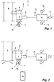
- a keyless engine start authorization control device 1 comprises an ignition starter switch 2.
- the ignition starter switch 2 is a mechanical Steering wheel lock 3 integrated, the bolt 4 in that shown in Figure 1 Position the rotational movement of the steering shaft 5 by radial intervention blocked in a bolt holder introduced into the steering spindle 5.
- the ignition starter switch 2 comprises an actuator 6, which is a physical Unit with the ignition starter switch 2 forms.
- the actuator 6 is rotatable both about its longitudinal axis and according to the The direction of the arrow can be pressed into the housing 7 of the ignition starter switch 2.
- a locking device 8 is also assigned to the ignition starter switch 2, with which the movement of the actuating element 6 can be mechanically blocked is. The locking device is in its position shown in FIG 8 in its blocking an actuator movement Position.
- the engine start authorization control device 1 further includes a transceiver 9 with an evaluation unit that is to be carried out a question-answer dialog with an ID transmitter shown in Figure 2 14 is provided.
- the illustrated transceiver 9 consists of three transmitters 10, 11, 12, each with different motor vehicle sides assigned.
- the transmitter 10 is on the driver side of the Motor vehicle, the transmitter 11 is arranged on the passenger side and the Transmitter 12 assigned to the rear area.
- the transmission ranges of the transmitters 10, 11, 12 only overlap in the interior of the motor vehicle.
- the transmitters 10, 11, 12 are used to send one directed to the ID transmitter 14 Question signal, which is preceded by a wake-up signal, the Transceiver 9 operated with the transmitters 10, 11, 12 so is that the ID transmitter 14 is located within the motor vehicle is possible.
- the transceiver 9 also includes a central receiving unit a receiving antenna 13 via which those sent back by the ID transmitter 14 Signals can be received. To start communication between the transceiver 9 and the ID transmitter 14 is on the handle 15 of the actuator 6 arranged electrical push button 16 provided.
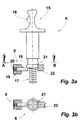
- the actuator 6 is the one acting on it Locking device 8 shown in its different positions.
- Figure 3a shows the actuator 6 in its initial position. In this Starting position is the axial directed against the coil spring 17 Movability of the actuator 6 by the locking bolt 18 of the locking device 8 blocked.
- the locking bolt 18 is by a solenoid 19 against the force of a spring 20 in its axial direction movable.
- the bordering on the lower end face of the actuator 6 The jacket section is tangentially flattened to form a sliding surface 21.
- This sliding surface 21 is adjacent to a sliding block 22, so that in this Position of the actuator 6 is prevented from rotating. From the 3b is the flattened configuration of the sliding surface 21 and the flat side adjoining the sliding surface 21 Setting stone 22 recognizable.
- the authorization request is made on the system side triggered.
- the locking device 8 controlled to move the locking bolt 18 so that the locking bolt 18 drawn against the spring 20 in the solenoid 19 becomes.
- the axial movement of the actuator 6 is then no longer blocked, so that this can be moved axially by pressing.
- the area of the lower section of the actuator 6 is circumferential trained holding and guide groove 23 introduced. Is the actuator 6 in the axial direction to the coil spring 17 by a predetermined Moved amount, the solenoid 19 is turned off, so that now the locking bolt 18 by the spring force 20 to the outer surface of the actuator is pressed.
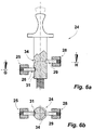
- Figure 5a shows another actuator 24, which is constructed similarly to the actuator 6 described in FIGS. 3a to 4b.
- a locking device 25 consisting of a locking bolt 26 and a solenoid 27 and a holding device 28 comprising a retaining bolt 29 and a lifting magnet 30.
- the locking device 25 serves to block a rotational movement of the Actuator 24 when it is in its initial position and if a rotary movement to bring about a steering spindle release and an engine start has not yet been released.
- the latch bolt In this position, 26 engages in one of the longitudinal axes of the actuator 24 following groove 31, the groove width essentially the diameter corresponds to the locking bolt 26.
- the engagement of the locking bolt 26 in the groove 31 can be clearly seen from the cross section of Figure 5b.
- the Groove 31 has a longitudinal extent so that the actuator 24 in the direction its longitudinal axis against the force of a coil spring 32 movable is. This freedom of movement is exploited to move through this an electrical switch, not shown in the figures close with which the authorization query is triggered. This Switch is closed when the actuator 24 towards it Longitudinal axis to the coil spring 32 is moved.
- the holding bolt 29 of the holding device 28 is by the force of a spring 33 pressed at the end against the outer lateral surface of the actuator 24.
- the holding bolt 29 does not have any effect in this position.
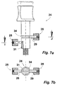
- FIG. 6a shows the actuator 26 in its wireless authorization request performing position.
- the holding magnet already grips in this position 29 of the holding device 28 into a circumference in the actuator 24 introduced retaining groove 34, since the actuator 24 is in this position is already in its rotational position.
- a rotary movement of the actuator 24 is however only released when the locking bolt 26 of the Locking device 25 has been moved out of the groove 31. If the authorization query dialog ends negatively, so that an unlock of the actuator 24 for releasing the rotary movement is not done the holding device 28 is subjected to a control command which leads to a Moving the solenoid 29 results from the holding groove 34.
- the Actuator 24 is then stored in the coil spring 32 Energy moves back to its original position.
- the deadbolt is released 26 moved out of the groove 31 by actuating the locking device 25, so that the rotary movement of the actuator 24 is now released is (see FIG. 7a).
- the entire angular range of the actuator 24 engages the retaining boss 29 in the retaining groove 34, so that a return movement the actuator in its initial position is not possible is.
- the travel position of the actuator 24 at which the retaining bolt 29 in the retaining groove 34 engages can also be seen from the cross section in FIG. 7b. In this position, the end face of the locking bolt 26 rests the outer surface of the actuator 24.
Landscapes
- Engineering & Computer Science (AREA)
- Mechanical Engineering (AREA)
- Lock And Its Accessories (AREA)
- Control Of Vehicle Engines Or Engines For Specific Uses (AREA)
Applications Claiming Priority (2)
| Application Number | Priority Date | Filing Date | Title |
|---|---|---|---|
| DE29902770U | 1999-02-17 | ||
| DE29902770U DE29902770U1 (de) | 1999-02-17 | 1999-02-17 | Manuell betätigbarer Zündanlaßschalter für eine schlüssellose Motorstartberechtigungskontrolleinrichtung eines Kraftfahrzeuges |
Publications (2)
| Publication Number | Publication Date |
|---|---|
| EP1029757A2 true EP1029757A2 (fr) | 2000-08-23 |
| EP1029757A3 EP1029757A3 (fr) | 2004-09-29 |
Family
ID=8069491
Family Applications (1)
| Application Number | Title | Priority Date | Filing Date |
|---|---|---|---|
| EP00102368A Withdrawn EP1029757A3 (fr) | 1999-02-17 | 2000-02-04 | Interrupteur d'allumage actionné manuellement pour un dispositif de contrôle d'autorisation sans clé du démarrage d'un véhicule à moteur |
Country Status (2)
| Country | Link |
|---|---|
| EP (1) | EP1029757A3 (fr) |
| DE (1) | DE29902770U1 (fr) |
Cited By (3)
| Publication number | Priority date | Publication date | Assignee | Title |
|---|---|---|---|---|
| WO2002092404A1 (fr) * | 2001-05-15 | 2002-11-21 | Leopold Kostal Gmbh & Co. Kg | Demarreur a commande manuelle pour unite sans cle servant au controle d'autorisation de demarrage de moteur d'un vehicule automobile |
| EP1262385A3 (fr) * | 2001-05-31 | 2004-01-02 | ArvinMeritor Light Vehicle Systems (UK) Ltd | Système de démarrage |
| DE102006054832B4 (de) | 2006-10-10 | 2018-09-27 | Hyundai Motor Company | Lenksäulen-Sperrvorrichtung mit Druck-Freigabefunktion |
Families Citing this family (2)
| Publication number | Priority date | Publication date | Assignee | Title |
|---|---|---|---|---|
| DE10010450C2 (de) * | 2000-03-03 | 2002-04-25 | Audi Ag | Fahrzeugverriegelungsvorrichtung |
| DE10144507B4 (de) * | 2001-09-10 | 2017-09-14 | Leopold Kostal Gmbh & Co. Kg | Zündanlaßschalter |
Family Cites Families (6)
| Publication number | Priority date | Publication date | Assignee | Title |
|---|---|---|---|---|
| US5036687A (en) * | 1989-07-31 | 1991-08-06 | Nissan Motor Company, Limited | Automotive steering lock system with portable radio code signal transmitter |
| US5801614A (en) | 1994-11-30 | 1998-09-01 | Kabushiki Kaisha Tokai-Rika-Denki-Seisakusho | Vehicle starting control device |
| JPH10315914A (ja) * | 1997-05-19 | 1998-12-02 | Tokai Rika Co Ltd | 車両用始動装置 |
| JP3142508B2 (ja) * | 1997-07-23 | 2001-03-07 | トヨタ自動車株式会社 | 車両電子キー装置 |
| DE19811786A1 (de) | 1998-03-18 | 1999-09-23 | Volkswagen Ag | Vorrichtung zum schlüssellosen Starten eines Kraftfahrzeuges |
| DE19860350C5 (de) * | 1998-12-24 | 2011-01-13 | Leopold Kostal Gmbh & Co. Kg | Schlüssellose Motorstartberechtigungskontrolleinrichung |
-
1999
- 1999-02-17 DE DE29902770U patent/DE29902770U1/de not_active Expired - Lifetime
-
2000
- 2000-02-04 EP EP00102368A patent/EP1029757A3/fr not_active Withdrawn
Non-Patent Citations (1)
| Title |
|---|
| None |
Cited By (3)
| Publication number | Priority date | Publication date | Assignee | Title |
|---|---|---|---|---|
| WO2002092404A1 (fr) * | 2001-05-15 | 2002-11-21 | Leopold Kostal Gmbh & Co. Kg | Demarreur a commande manuelle pour unite sans cle servant au controle d'autorisation de demarrage de moteur d'un vehicule automobile |
| EP1262385A3 (fr) * | 2001-05-31 | 2004-01-02 | ArvinMeritor Light Vehicle Systems (UK) Ltd | Système de démarrage |
| DE102006054832B4 (de) | 2006-10-10 | 2018-09-27 | Hyundai Motor Company | Lenksäulen-Sperrvorrichtung mit Druck-Freigabefunktion |
Also Published As
| Publication number | Publication date |
|---|---|
| DE29902770U1 (de) | 1999-04-29 |
| EP1029757A3 (fr) | 2004-09-29 |
Similar Documents
| Publication | Publication Date | Title |
|---|---|---|
| EP1268959B1 (fr) | Systeme d'acces pour vehicule | |
| DE19956300B4 (de) | Lenkradschlossvorrichtung | |
| DE3436761C2 (fr) | ||
| DE4434587A1 (de) | Elektronisches Zündstartschloßsystem an einem Kraftfahrzeug | |
| EP0846820A1 (fr) | Système de verrouillage, notamment pour un véhicule à moteur | |
| EP2700545B1 (fr) | Procédé de fonctionnement d'un système de commande d'une moto | |
| EP0935543A1 (fr) | Dispositif avec un cylindre de fermeture et un commutateur de fonctions electriques diverses, notamment contacteur d'allumage pour vehicules a moteur | |
| WO2001033017A1 (fr) | Dispositif de verrouillage de portiere d'un vehicule a moteur | |
| EP1135284B1 (fr) | Systeme de fermeture, notamment pour automobiles | |
| DE102004063240B4 (de) | Lenkschloss für Persönliche-Identifikationskarte-System | |
| DE19957624C2 (de) | Elektronisches Lenkschloß und elektronischer Zündanlaßschalter für Kraftfahrzeuge | |
| EP1029757A2 (fr) | Interrupteur d'allumage actionné manuellement pour un dispositif de contrôle d'autorisation sans clé du démarrage d'un véhicule à moteur | |
| DE19860350B4 (de) | Schlüssellose Motorstartberechtigungskontrolleinrichung | |
| EP1121278B1 (fr) | Dispositif de commande pour l'allumage et le blocage de la direction d'une automobile | |
| EP0721869B1 (fr) | Dispositif de verrouillage pour véhicules | |
| DE4314854C2 (de) | Lenkschloß | |
| DE3318359C2 (de) | Lenk- und Zündschloß für Kraftfahrzeuge | |
| DE19957546C2 (de) | Lenkschloß für Kraftfahrzeuge | |
| DE19838992C2 (de) | Zündanlaßschalter für Kraftfahrzeuge mit elektronischer Lenkungsverriegelung | |
| EP2651701B1 (fr) | Dispositif de verrouillage mécanique pour motocycle | |
| DE3521570C2 (de) | Mit einer Fernbedienungseinrichtung ausgerüstete Zentralverriegelungsanlage für ein Kraftfahrzeug | |
| AT401760B (de) | Schaltsperre für kraftfahrzeuge mit schaltgetriebe oder automatgetriebe als diebstahlsicherung | |
| EP3453579B1 (fr) | Dispositif de verrouillage | |
| DE10238886B4 (de) | Startvorrichtung für ein Kraftfahrzeug, welches ein Lenkelement zur Fahrtrichtungswahl aufweist, sowie Startverfahren hierfür | |
| WO2002092403A1 (fr) | Systeme de commande d'autorisation de demarrage de moteur sans cle pour vehicules automobiles |
Legal Events
| Date | Code | Title | Description |
|---|---|---|---|
| PUAI | Public reference made under article 153(3) epc to a published international application that has entered the european phase |
Free format text: ORIGINAL CODE: 0009012 |
|
| AK | Designated contracting states |
Kind code of ref document: A2 Designated state(s): AT BE CH CY DE DK ES FI FR GB GR IE IT LI LU MC NL PT SE |
|
| AX | Request for extension of the european patent |
Free format text: AL;LT;LV;MK;RO;SI |
|
| PUAL | Search report despatched |
Free format text: ORIGINAL CODE: 0009013 |
|
| AK | Designated contracting states |
Kind code of ref document: A3 Designated state(s): AT BE CH CY DE DK ES FI FR GB GR IE IT LI LU MC NL PT SE |
|
| AX | Request for extension of the european patent |
Extension state: AL LT LV MK RO SI |
|
| AKX | Designation fees paid | ||
| REG | Reference to a national code |
Ref country code: DE Ref legal event code: 8566 |
|
| STAA | Information on the status of an ep patent application or granted ep patent |
Free format text: STATUS: THE APPLICATION IS DEEMED TO BE WITHDRAWN |
|
| 18D | Application deemed to be withdrawn |
Effective date: 20050330 |