EP2696245B1 - Conductive member, process cartridge, and electrophotographic device - Google Patents
Conductive member, process cartridge, and electrophotographic device Download PDFInfo
- Publication number
- EP2696245B1 EP2696245B1 EP12767902.5A EP12767902A EP2696245B1 EP 2696245 B1 EP2696245 B1 EP 2696245B1 EP 12767902 A EP12767902 A EP 12767902A EP 2696245 B1 EP2696245 B1 EP 2696245B1
- Authority
- EP
- European Patent Office
- Prior art keywords
- block
- group
- conductive
- conductive member
- microphase
- Prior art date
- Legal status (The legal status is an assumption and is not a legal conclusion. Google has not performed a legal analysis and makes no representation as to the accuracy of the status listed.)
- Not-in-force
Links
- 238000000034 method Methods 0.000 title claims description 26
- 230000008569 process Effects 0.000 title claims description 9
- 229920000642 polymer Polymers 0.000 claims description 59
- 229920000428 triblock copolymer Polymers 0.000 claims description 32
- 238000005342 ion exchange Methods 0.000 claims description 27
- 125000003178 carboxy group Chemical group [H]OC(*)=O 0.000 claims description 26
- 125000004435 hydrogen atom Chemical group [H]* 0.000 claims description 14
- 239000011159 matrix material Substances 0.000 claims description 12
- 125000002887 hydroxy group Chemical group [H]O* 0.000 claims description 8
- 241000047703 Nonion Species 0.000 claims description 6
- 125000002496 methyl group Chemical group [H]C([H])([H])* 0.000 claims description 4
- 229910006069 SO3H Inorganic materials 0.000 claims description 3
- 125000004432 carbon atom Chemical group C* 0.000 claims description 2
- 229930195734 saturated hydrocarbon Natural products 0.000 claims description 2
- 125000001183 hydrocarbyl group Chemical group 0.000 claims 1
- 229920002725 thermoplastic elastomer Polymers 0.000 description 88
- 238000011156 evaluation Methods 0.000 description 85
- RRHGJUQNOFWUDK-UHFFFAOYSA-N Isoprene Chemical compound CC(=C)C=C RRHGJUQNOFWUDK-UHFFFAOYSA-N 0.000 description 72
- KAKZBPTYRLMSJV-UHFFFAOYSA-N Butadiene Chemical group C=CC=C KAKZBPTYRLMSJV-UHFFFAOYSA-N 0.000 description 71
- PPBRXRYQALVLMV-UHFFFAOYSA-N Styrene Chemical group C=CC1=CC=CC=C1 PPBRXRYQALVLMV-UHFFFAOYSA-N 0.000 description 68
- 239000010410 layer Substances 0.000 description 47
- 229920001971 elastomer Polymers 0.000 description 34
- SMZOUWXMTYCWNB-UHFFFAOYSA-N 2-(2-methoxy-5-methylphenyl)ethanamine Chemical compound COC1=CC=C(C)C=C1CCN SMZOUWXMTYCWNB-UHFFFAOYSA-N 0.000 description 29
- NIXOWILDQLNWCW-UHFFFAOYSA-N 2-Propenoic acid Natural products OC(=O)C=C NIXOWILDQLNWCW-UHFFFAOYSA-N 0.000 description 29
- OKKJLVBELUTLKV-UHFFFAOYSA-N Methanol Chemical compound OC OKKJLVBELUTLKV-UHFFFAOYSA-N 0.000 description 27
- 239000000806 elastomer Substances 0.000 description 26
- VVQNEPGJFQJSBK-UHFFFAOYSA-N Methyl methacrylate Chemical group COC(=O)C(C)=C VVQNEPGJFQJSBK-UHFFFAOYSA-N 0.000 description 25
- 239000000203 mixture Substances 0.000 description 24
- 150000002500 ions Chemical class 0.000 description 22
- 239000000243 solution Substances 0.000 description 22
- 238000002156 mixing Methods 0.000 description 20
- YXFVVABEGXRONW-UHFFFAOYSA-N Toluene Chemical compound CC1=CC=CC=C1 YXFVVABEGXRONW-UHFFFAOYSA-N 0.000 description 18
- 229920001577 copolymer Polymers 0.000 description 17
- 150000001993 dienes Chemical class 0.000 description 17
- 239000003795 chemical substances by application Substances 0.000 description 14
- 230000015572 biosynthetic process Effects 0.000 description 13
- 229910052751 metal Inorganic materials 0.000 description 12
- 239000002184 metal Substances 0.000 description 12
- 238000000425 proton nuclear magnetic resonance spectrum Methods 0.000 description 12
- 238000006243 chemical reaction Methods 0.000 description 11
- 230000000052 comparative effect Effects 0.000 description 11
- 229920000346 polystyrene-polyisoprene block-polystyrene Polymers 0.000 description 11
- 238000003786 synthesis reaction Methods 0.000 description 10
- 238000012546 transfer Methods 0.000 description 10
- YMWUJEATGCHHMB-UHFFFAOYSA-N Dichloromethane Chemical compound ClCCl YMWUJEATGCHHMB-UHFFFAOYSA-N 0.000 description 9
- ZMXDDKWLCZADIW-UHFFFAOYSA-N N,N-Dimethylformamide Chemical compound CN(C)C=O ZMXDDKWLCZADIW-UHFFFAOYSA-N 0.000 description 9
- 239000002174 Styrene-butadiene Substances 0.000 description 9
- QAOWNCQODCNURD-UHFFFAOYSA-N Sulfuric acid Chemical compound OS(O)(=O)=O QAOWNCQODCNURD-UHFFFAOYSA-N 0.000 description 9
- MTAZNLWOLGHBHU-UHFFFAOYSA-N butadiene-styrene rubber Chemical compound C=CC=C.C=CC1=CC=CC=C1 MTAZNLWOLGHBHU-UHFFFAOYSA-N 0.000 description 9
- 239000011115 styrene butadiene Substances 0.000 description 9
- 229920003048 styrene butadiene rubber Polymers 0.000 description 9
- 229920001400 block copolymer Polymers 0.000 description 8
- 238000000465 moulding Methods 0.000 description 8
- 239000005060 rubber Substances 0.000 description 8
- 239000007795 chemical reaction product Substances 0.000 description 7
- 239000000463 material Substances 0.000 description 7
- 239000004793 Polystyrene Substances 0.000 description 6
- 239000011230 binding agent Substances 0.000 description 6
- RXLSZKRKKCDZOQ-UHFFFAOYSA-N methyl 2-methylprop-2-enoate;prop-2-enoic acid Chemical compound OC(=O)C=C.COC(=O)C(C)=C.COC(=O)C(C)=C RXLSZKRKKCDZOQ-UHFFFAOYSA-N 0.000 description 6
- ABLZXFCXXLZCGV-UHFFFAOYSA-N phosphonic acid group Chemical group P(O)(O)=O ABLZXFCXXLZCGV-UHFFFAOYSA-N 0.000 description 6
- 229920002223 polystyrene Polymers 0.000 description 6
- 238000007334 copolymerization reaction Methods 0.000 description 5
- 238000004090 dissolution Methods 0.000 description 5
- IJGRMHOSHXDMSA-UHFFFAOYSA-N nitrogen Substances N#N IJGRMHOSHXDMSA-UHFFFAOYSA-N 0.000 description 5
- -1 polyethylene-propylene Polymers 0.000 description 5
- 150000008053 sultones Chemical class 0.000 description 5
- 230000003746 surface roughness Effects 0.000 description 5
- QTBSBXVTEAMEQO-UHFFFAOYSA-N Acetic acid Chemical compound CC(O)=O QTBSBXVTEAMEQO-UHFFFAOYSA-N 0.000 description 4
- PXHVJJICTQNCMI-UHFFFAOYSA-N Nickel Chemical compound [Ni] PXHVJJICTQNCMI-UHFFFAOYSA-N 0.000 description 4
- NBIIXXVUZAFLBC-UHFFFAOYSA-N Phosphoric acid Chemical compound OP(O)(O)=O NBIIXXVUZAFLBC-UHFFFAOYSA-N 0.000 description 4
- JUJWROOIHBZHMG-UHFFFAOYSA-N Pyridine Chemical compound C1=CC=NC=C1 JUJWROOIHBZHMG-UHFFFAOYSA-N 0.000 description 4
- 229920002125 Sokalan® Polymers 0.000 description 4
- 230000008901 benefit Effects 0.000 description 4
- 229910052799 carbon Inorganic materials 0.000 description 4
- 239000003999 initiator Substances 0.000 description 4
- 239000007788 liquid Substances 0.000 description 4
- 239000012299 nitrogen atmosphere Substances 0.000 description 4
- 229920003229 poly(methyl methacrylate) Polymers 0.000 description 4
- 238000006116 polymerization reaction Methods 0.000 description 4
- 239000004926 polymethyl methacrylate Substances 0.000 description 4
- 239000000047 product Substances 0.000 description 4
- 238000001226 reprecipitation Methods 0.000 description 4
- 229920001897 terpolymer Polymers 0.000 description 4
- HVLLSGMXQDNUAL-UHFFFAOYSA-N triphenyl phosphite Chemical compound C=1C=CC=CC=1OP(OC=1C=CC=CC=1)OC1=CC=CC=C1 HVLLSGMXQDNUAL-UHFFFAOYSA-N 0.000 description 4
- 238000005406 washing Methods 0.000 description 4
- XEKOWRVHYACXOJ-UHFFFAOYSA-N Ethyl acetate Chemical compound CCOC(C)=O XEKOWRVHYACXOJ-UHFFFAOYSA-N 0.000 description 3
- KFZMGEQAYNKOFK-UHFFFAOYSA-N Isopropanol Chemical compound CC(C)O KFZMGEQAYNKOFK-UHFFFAOYSA-N 0.000 description 3
- 239000005062 Polybutadiene Substances 0.000 description 3
- 238000004140 cleaning Methods 0.000 description 3
- 150000001875 compounds Chemical class 0.000 description 3
- 238000005227 gel permeation chromatography Methods 0.000 description 3
- 230000009477 glass transition Effects 0.000 description 3
- 101150085091 lat-2 gene Proteins 0.000 description 3
- 238000005259 measurement Methods 0.000 description 3
- 239000002808 molecular sieve Substances 0.000 description 3
- VLKZOEOYAKHREP-UHFFFAOYSA-N n-Hexane Chemical compound CCCCCC VLKZOEOYAKHREP-UHFFFAOYSA-N 0.000 description 3
- 229910052757 nitrogen Inorganic materials 0.000 description 3
- 239000004584 polyacrylic acid Substances 0.000 description 3
- 229920002857 polybutadiene Polymers 0.000 description 3
- URGAHOPLAPQHLN-UHFFFAOYSA-N sodium aluminosilicate Chemical compound [Na+].[Al+3].[O-][Si]([O-])=O.[O-][Si]([O-])=O URGAHOPLAPQHLN-UHFFFAOYSA-N 0.000 description 3
- 229920000468 styrene butadiene styrene block copolymer Polymers 0.000 description 3
- 239000002344 surface layer Substances 0.000 description 3
- 238000004073 vulcanization Methods 0.000 description 3
- XLYOFNOQVPJJNP-UHFFFAOYSA-N water Substances O XLYOFNOQVPJJNP-UHFFFAOYSA-N 0.000 description 3
- ZMCHBSMFKQYNKA-UHFFFAOYSA-N 2-aminobenzenesulfonic acid Chemical compound NC1=CC=CC=C1S(O)(=O)=O ZMCHBSMFKQYNKA-UHFFFAOYSA-N 0.000 description 2
- XKRFYHLGVUSROY-UHFFFAOYSA-N Argon Chemical compound [Ar] XKRFYHLGVUSROY-UHFFFAOYSA-N 0.000 description 2
- HEDRZPFGACZZDS-UHFFFAOYSA-N Chloroform Chemical compound ClC(Cl)Cl HEDRZPFGACZZDS-UHFFFAOYSA-N 0.000 description 2
- 229910021589 Copper(I) bromide Inorganic materials 0.000 description 2
- VEXZGXHMUGYJMC-UHFFFAOYSA-N Hydrochloric acid Chemical compound Cl VEXZGXHMUGYJMC-UHFFFAOYSA-N 0.000 description 2
- XEEYBQQBJWHFJM-UHFFFAOYSA-N Iron Chemical compound [Fe] XEEYBQQBJWHFJM-UHFFFAOYSA-N 0.000 description 2
- 229920002367 Polyisobutene Polymers 0.000 description 2
- VYPSYNLAJGMNEJ-UHFFFAOYSA-N Silicium dioxide Chemical compound O=[Si]=O VYPSYNLAJGMNEJ-UHFFFAOYSA-N 0.000 description 2
- WYURNTSHIVDZCO-UHFFFAOYSA-N Tetrahydrofuran Chemical compound C1CCOC1 WYURNTSHIVDZCO-UHFFFAOYSA-N 0.000 description 2
- DTQVDTLACAAQTR-UHFFFAOYSA-N Trifluoroacetic acid Chemical compound OC(=O)C(F)(F)F DTQVDTLACAAQTR-UHFFFAOYSA-N 0.000 description 2
- 229960000583 acetic acid Drugs 0.000 description 2
- 229910052782 aluminium Inorganic materials 0.000 description 2
- XAGFODPZIPBFFR-UHFFFAOYSA-N aluminium Chemical compound [Al] XAGFODPZIPBFFR-UHFFFAOYSA-N 0.000 description 2
- 229910000147 aluminium phosphate Inorganic materials 0.000 description 2
- 239000012300 argon atmosphere Substances 0.000 description 2
- 230000005540 biological transmission Effects 0.000 description 2
- 230000015556 catabolic process Effects 0.000 description 2
- 230000008859 change Effects 0.000 description 2
- NKNDPYCGAZPOFS-UHFFFAOYSA-M copper(i) bromide Chemical compound Br[Cu] NKNDPYCGAZPOFS-UHFFFAOYSA-M 0.000 description 2
- 238000004132 cross linking Methods 0.000 description 2
- 238000010511 deprotection reaction Methods 0.000 description 2
- 238000010586 diagram Methods 0.000 description 2
- 238000009826 distribution Methods 0.000 description 2
- 230000000694 effects Effects 0.000 description 2
- 239000012362 glacial acetic acid Substances 0.000 description 2
- 238000010438 heat treatment Methods 0.000 description 2
- 230000007774 longterm Effects 0.000 description 2
- DWFKOMDBEKIATP-UHFFFAOYSA-N n'-[2-[2-(dimethylamino)ethyl-methylamino]ethyl]-n,n,n'-trimethylethane-1,2-diamine Chemical compound CN(C)CCN(C)CCN(C)CCN(C)C DWFKOMDBEKIATP-UHFFFAOYSA-N 0.000 description 2
- 229910052759 nickel Inorganic materials 0.000 description 2
- 239000002245 particle Substances 0.000 description 2
- 125000002467 phosphate group Chemical group [H]OP(=O)(O[H])O[*] 0.000 description 2
- 230000000379 polymerizing effect Effects 0.000 description 2
- 238000003825 pressing Methods 0.000 description 2
- UMJSCPRVCHMLSP-UHFFFAOYSA-N pyridine Natural products COC1=CC=CN=C1 UMJSCPRVCHMLSP-UHFFFAOYSA-N 0.000 description 2
- 238000000197 pyrolysis Methods 0.000 description 2
- 239000002994 raw material Substances 0.000 description 2
- 239000011347 resin Substances 0.000 description 2
- 229920005989 resin Polymers 0.000 description 2
- 229920006395 saturated elastomer Polymers 0.000 description 2
- 238000000235 small-angle X-ray scattering Methods 0.000 description 2
- ISXSCDLOGDJUNJ-UHFFFAOYSA-N tert-butyl prop-2-enoate Chemical compound CC(C)(C)OC(=O)C=C ISXSCDLOGDJUNJ-UHFFFAOYSA-N 0.000 description 2
- INDYTVBCIOVVRC-UHFFFAOYSA-M trimethyl(octyl)azanium;perchlorate Chemical compound [O-]Cl(=O)(=O)=O.CCCCCCCC[N+](C)(C)C INDYTVBCIOVVRC-UHFFFAOYSA-M 0.000 description 2
- NWUYHJFMYQTDRP-UHFFFAOYSA-N 1,2-bis(ethenyl)benzene;1-ethenyl-2-ethylbenzene;styrene Chemical compound C=CC1=CC=CC=C1.CCC1=CC=CC=C1C=C.C=CC1=CC=CC=C1C=C NWUYHJFMYQTDRP-UHFFFAOYSA-N 0.000 description 1
- ROGIWVXWXZRRMZ-UHFFFAOYSA-N 2-methylbuta-1,3-diene;styrene Chemical compound CC(=C)C=C.C=CC1=CC=CC=C1 ROGIWVXWXZRRMZ-UHFFFAOYSA-N 0.000 description 1
- ICGLPKIVTVWCFT-UHFFFAOYSA-N 4-methylbenzenesulfonohydrazide Chemical compound CC1=CC=C(S(=O)(=O)NN)C=C1 ICGLPKIVTVWCFT-UHFFFAOYSA-N 0.000 description 1
- WKBOTKDWSSQWDR-UHFFFAOYSA-N Bromine atom Chemical compound [Br] WKBOTKDWSSQWDR-UHFFFAOYSA-N 0.000 description 1
- RYGMFSIKBFXOCR-UHFFFAOYSA-N Copper Chemical compound [Cu] RYGMFSIKBFXOCR-UHFFFAOYSA-N 0.000 description 1
- XDTMQSROBMDMFD-UHFFFAOYSA-N Cyclohexane Chemical compound C1CCCCC1 XDTMQSROBMDMFD-UHFFFAOYSA-N 0.000 description 1
- JOYRKODLDBILNP-UHFFFAOYSA-N Ethyl urethane Chemical compound CCOC(N)=O JOYRKODLDBILNP-UHFFFAOYSA-N 0.000 description 1
- 229920000459 Nitrile rubber Polymers 0.000 description 1
- 239000006057 Non-nutritive feed additive Substances 0.000 description 1
- KEAYESYHFKHZAL-UHFFFAOYSA-N Sodium Chemical compound [Na] KEAYESYHFKHZAL-UHFFFAOYSA-N 0.000 description 1
- 239000004902 Softening Agent Substances 0.000 description 1
- RTAQQCXQSZGOHL-UHFFFAOYSA-N Titanium Chemical compound [Ti] RTAQQCXQSZGOHL-UHFFFAOYSA-N 0.000 description 1
- 229920006311 Urethane elastomer Polymers 0.000 description 1
- 238000004220 aggregation Methods 0.000 description 1
- 230000002776 aggregation Effects 0.000 description 1
- 229910045601 alloy Inorganic materials 0.000 description 1
- 239000000956 alloy Substances 0.000 description 1
- PNEYBMLMFCGWSK-UHFFFAOYSA-N aluminium oxide Inorganic materials [O-2].[O-2].[O-2].[Al+3].[Al+3] PNEYBMLMFCGWSK-UHFFFAOYSA-N 0.000 description 1
- 238000010539 anionic addition polymerization reaction Methods 0.000 description 1
- 239000007864 aqueous solution Substances 0.000 description 1
- 229910052786 argon Inorganic materials 0.000 description 1
- QVGXLLKOCUKJST-UHFFFAOYSA-N atomic oxygen Chemical group [O] QVGXLLKOCUKJST-UHFFFAOYSA-N 0.000 description 1
- GDTBXPJZTBHREO-UHFFFAOYSA-N bromine Substances BrBr GDTBXPJZTBHREO-UHFFFAOYSA-N 0.000 description 1
- 229910052794 bromium Inorganic materials 0.000 description 1
- RTACIUYXLGWTAE-UHFFFAOYSA-N buta-1,3-diene;2-methylbuta-1,3-diene;styrene Chemical compound C=CC=C.CC(=C)C=C.C=CC1=CC=CC=C1 RTACIUYXLGWTAE-UHFFFAOYSA-N 0.000 description 1
- CQEYYJKEWSMYFG-UHFFFAOYSA-N butyl acrylate Chemical compound CCCCOC(=O)C=C CQEYYJKEWSMYFG-UHFFFAOYSA-N 0.000 description 1
- 239000006229 carbon black Substances 0.000 description 1
- 150000001732 carboxylic acid derivatives Chemical class 0.000 description 1
- 239000000969 carrier Substances 0.000 description 1
- 239000003086 colorant Substances 0.000 description 1
- 238000013329 compounding Methods 0.000 description 1
- 230000006835 compression Effects 0.000 description 1
- 238000007906 compression Methods 0.000 description 1
- 238000000748 compression moulding Methods 0.000 description 1
- 239000004020 conductor Substances 0.000 description 1
- 238000001816 cooling Methods 0.000 description 1
- 229910052802 copper Inorganic materials 0.000 description 1
- 239000010949 copper Substances 0.000 description 1
- 238000005520 cutting process Methods 0.000 description 1
- 238000000151 deposition Methods 0.000 description 1
- 238000011161 development Methods 0.000 description 1
- 229910003460 diamond Inorganic materials 0.000 description 1
- 239000010432 diamond Substances 0.000 description 1
- 238000002050 diffraction method Methods 0.000 description 1
- AWWJYEJSCIDADZ-UHFFFAOYSA-N dimethyl 2,6-dibromoheptanedioate Chemical compound COC(=O)C(Br)CCCC(Br)C(=O)OC AWWJYEJSCIDADZ-UHFFFAOYSA-N 0.000 description 1
- 239000002270 dispersing agent Substances 0.000 description 1
- 238000001704 evaporation Methods 0.000 description 1
- 230000008020 evaporation Effects 0.000 description 1
- 238000001125 extrusion Methods 0.000 description 1
- 239000000945 filler Substances 0.000 description 1
- 239000010419 fine particle Substances 0.000 description 1
- 239000004088 foaming agent Substances 0.000 description 1
- 150000002430 hydrocarbons Chemical group 0.000 description 1
- 230000002209 hydrophobic effect Effects 0.000 description 1
- 230000001771 impaired effect Effects 0.000 description 1
- 238000001746 injection moulding Methods 0.000 description 1
- 230000003993 interaction Effects 0.000 description 1
- 238000011835 investigation Methods 0.000 description 1
- 239000003456 ion exchange resin Substances 0.000 description 1
- 229920003303 ion-exchange polymer Polymers 0.000 description 1
- 229920000554 ionomer Polymers 0.000 description 1
- 229910052742 iron Inorganic materials 0.000 description 1
- 230000002427 irreversible effect Effects 0.000 description 1
- WGOPGODQLGJZGL-UHFFFAOYSA-N lithium;butane Chemical compound [Li+].CC[CH-]C WGOPGODQLGJZGL-UHFFFAOYSA-N 0.000 description 1
- 238000010550 living polymerization reaction Methods 0.000 description 1
- 238000004519 manufacturing process Methods 0.000 description 1
- 238000002844 melting Methods 0.000 description 1
- 230000008018 melting Effects 0.000 description 1
- 150000002739 metals Chemical class 0.000 description 1
- 239000000178 monomer Substances 0.000 description 1
- QJGQUHMNIGDVPM-UHFFFAOYSA-N nitrogen group Chemical group [N] QJGQUHMNIGDVPM-UHFFFAOYSA-N 0.000 description 1
- 239000012044 organic layer Substances 0.000 description 1
- 239000001301 oxygen Substances 0.000 description 1
- 229910052760 oxygen Inorganic materials 0.000 description 1
- 230000000737 periodic effect Effects 0.000 description 1
- 238000005191 phase separation Methods 0.000 description 1
- IYDGMDWEHDFVQI-UHFFFAOYSA-N phosphoric acid;trioxotungsten Chemical compound O=[W](=O)=O.O=[W](=O)=O.O=[W](=O)=O.O=[W](=O)=O.O=[W](=O)=O.O=[W](=O)=O.O=[W](=O)=O.O=[W](=O)=O.O=[W](=O)=O.O=[W](=O)=O.O=[W](=O)=O.O=[W](=O)=O.OP(O)(O)=O IYDGMDWEHDFVQI-UHFFFAOYSA-N 0.000 description 1
- OJMIONKXNSYLSR-UHFFFAOYSA-N phosphorous acid Chemical group OP(O)O OJMIONKXNSYLSR-UHFFFAOYSA-N 0.000 description 1
- 238000007747 plating Methods 0.000 description 1
- 229920006112 polar polymer Polymers 0.000 description 1
- 238000005498 polishing Methods 0.000 description 1
- 229920000728 polyester Polymers 0.000 description 1
- 229920001195 polyisoprene Polymers 0.000 description 1
- 239000002244 precipitate Substances 0.000 description 1
- 239000011241 protective layer Substances 0.000 description 1
- 238000000746 purification Methods 0.000 description 1
- 150000003242 quaternary ammonium salts Chemical class 0.000 description 1
- 238000010791 quenching Methods 0.000 description 1
- 230000000171 quenching effect Effects 0.000 description 1
- 238000010526 radical polymerization reaction Methods 0.000 description 1
- 229920005604 random copolymer Polymers 0.000 description 1
- 238000010992 reflux Methods 0.000 description 1
- 239000011369 resultant mixture Substances 0.000 description 1
- 229910001927 ruthenium tetroxide Inorganic materials 0.000 description 1
- 239000000377 silicon dioxide Substances 0.000 description 1
- 229910000104 sodium hydride Inorganic materials 0.000 description 1
- 239000012312 sodium hydride Substances 0.000 description 1
- 239000002904 solvent Substances 0.000 description 1
- 238000010186 staining Methods 0.000 description 1
- 238000003756 stirring Methods 0.000 description 1
- 238000006467 substitution reaction Methods 0.000 description 1
- 239000000758 substrate Substances 0.000 description 1
- BDHFUVZGWQCTTF-UHFFFAOYSA-M sulfonate Chemical compound [O-]S(=O)=O BDHFUVZGWQCTTF-UHFFFAOYSA-M 0.000 description 1
- 238000006277 sulfonation reaction Methods 0.000 description 1
- 125000000999 tert-butyl group Chemical group [H]C([H])([H])C(*)(C([H])([H])[H])C([H])([H])[H] 0.000 description 1
- YLQBMQCUIZJEEH-UHFFFAOYSA-N tetrahydrofuran Natural products C=1C=COC=1 YLQBMQCUIZJEEH-UHFFFAOYSA-N 0.000 description 1
- 229920002803 thermoplastic polyurethane Polymers 0.000 description 1
- 229920001187 thermosetting polymer Polymers 0.000 description 1
- 239000010936 titanium Substances 0.000 description 1
- 229910052719 titanium Inorganic materials 0.000 description 1
- 230000001131 transforming effect Effects 0.000 description 1
- 238000001291 vacuum drying Methods 0.000 description 1
Images


Classifications
-
- G—PHYSICS
- G03—PHOTOGRAPHY; CINEMATOGRAPHY; ANALOGOUS TECHNIQUES USING WAVES OTHER THAN OPTICAL WAVES; ELECTROGRAPHY; HOLOGRAPHY
- G03G—ELECTROGRAPHY; ELECTROPHOTOGRAPHY; MAGNETOGRAPHY
- G03G15/00—Apparatus for electrographic processes using a charge pattern
- G03G15/02—Apparatus for electrographic processes using a charge pattern for laying down a uniform charge, e.g. for sensitising; Corona discharge devices
- G03G15/0208—Apparatus for electrographic processes using a charge pattern for laying down a uniform charge, e.g. for sensitising; Corona discharge devices by contact, friction or induction, e.g. liquid charging apparatus
- G03G15/0216—Apparatus for electrographic processes using a charge pattern for laying down a uniform charge, e.g. for sensitising; Corona discharge devices by contact, friction or induction, e.g. liquid charging apparatus by bringing a charging member into contact with the member to be charged, e.g. roller, brush chargers
- G03G15/0233—Structure, details of the charging member, e.g. chemical composition, surface properties
-
- G—PHYSICS
- G03—PHOTOGRAPHY; CINEMATOGRAPHY; ANALOGOUS TECHNIQUES USING WAVES OTHER THAN OPTICAL WAVES; ELECTROGRAPHY; HOLOGRAPHY
- G03G—ELECTROGRAPHY; ELECTROPHOTOGRAPHY; MAGNETOGRAPHY
- G03G15/00—Apparatus for electrographic processes using a charge pattern
- G03G15/02—Apparatus for electrographic processes using a charge pattern for laying down a uniform charge, e.g. for sensitising; Corona discharge devices
-
- C—CHEMISTRY; METALLURGY
- C08—ORGANIC MACROMOLECULAR COMPOUNDS; THEIR PREPARATION OR CHEMICAL WORKING-UP; COMPOSITIONS BASED THEREON
- C08F—MACROMOLECULAR COMPOUNDS OBTAINED BY REACTIONS ONLY INVOLVING CARBON-TO-CARBON UNSATURATED BONDS
- C08F297/00—Macromolecular compounds obtained by successively polymerising different monomer systems using a catalyst of the ionic or coordination type without deactivating the intermediate polymer
- C08F297/02—Macromolecular compounds obtained by successively polymerising different monomer systems using a catalyst of the ionic or coordination type without deactivating the intermediate polymer using a catalyst of the anionic type
-
- G—PHYSICS
- G03—PHOTOGRAPHY; CINEMATOGRAPHY; ANALOGOUS TECHNIQUES USING WAVES OTHER THAN OPTICAL WAVES; ELECTROGRAPHY; HOLOGRAPHY
- G03G—ELECTROGRAPHY; ELECTROPHOTOGRAPHY; MAGNETOGRAPHY
- G03G15/00—Apparatus for electrographic processes using a charge pattern
- G03G15/06—Apparatus for electrographic processes using a charge pattern for developing
- G03G15/08—Apparatus for electrographic processes using a charge pattern for developing using a solid developer, e.g. powder developer
- G03G15/0806—Apparatus for electrographic processes using a charge pattern for developing using a solid developer, e.g. powder developer on a donor element, e.g. belt, roller
- G03G15/0818—Apparatus for electrographic processes using a charge pattern for developing using a solid developer, e.g. powder developer on a donor element, e.g. belt, roller characterised by the structure of the donor member, e.g. surface properties
-
- G—PHYSICS
- G03—PHOTOGRAPHY; CINEMATOGRAPHY; ANALOGOUS TECHNIQUES USING WAVES OTHER THAN OPTICAL WAVES; ELECTROGRAPHY; HOLOGRAPHY
- G03G—ELECTROGRAPHY; ELECTROPHOTOGRAPHY; MAGNETOGRAPHY
- G03G15/00—Apparatus for electrographic processes using a charge pattern
- G03G15/14—Apparatus for electrographic processes using a charge pattern for transferring a pattern to a second base
- G03G15/16—Apparatus for electrographic processes using a charge pattern for transferring a pattern to a second base of a toner pattern, e.g. a powder pattern, e.g. magnetic transfer
- G03G15/1665—Apparatus for electrographic processes using a charge pattern for transferring a pattern to a second base of a toner pattern, e.g. a powder pattern, e.g. magnetic transfer by introducing the second base in the nip formed by the recording member and at least one transfer member, e.g. in combination with bias or heat
- G03G15/167—Apparatus for electrographic processes using a charge pattern for transferring a pattern to a second base of a toner pattern, e.g. a powder pattern, e.g. magnetic transfer by introducing the second base in the nip formed by the recording member and at least one transfer member, e.g. in combination with bias or heat at least one of the recording member or the transfer member being rotatable during the transfer
- G03G15/1685—Structure, details of the transfer member, e.g. chemical composition
-
- Y—GENERAL TAGGING OF NEW TECHNOLOGICAL DEVELOPMENTS; GENERAL TAGGING OF CROSS-SECTIONAL TECHNOLOGIES SPANNING OVER SEVERAL SECTIONS OF THE IPC; TECHNICAL SUBJECTS COVERED BY FORMER USPC CROSS-REFERENCE ART COLLECTIONS [XRACs] AND DIGESTS
- Y10—TECHNICAL SUBJECTS COVERED BY FORMER USPC
- Y10T—TECHNICAL SUBJECTS COVERED BY FORMER US CLASSIFICATION
- Y10T428/00—Stock material or miscellaneous articles
- Y10T428/31504—Composite [nonstructural laminate]
- Y10T428/31786—Of polyester [e.g., alkyd, etc.]
-
- Y—GENERAL TAGGING OF NEW TECHNOLOGICAL DEVELOPMENTS; GENERAL TAGGING OF CROSS-SECTIONAL TECHNOLOGIES SPANNING OVER SEVERAL SECTIONS OF THE IPC; TECHNICAL SUBJECTS COVERED BY FORMER USPC CROSS-REFERENCE ART COLLECTIONS [XRACs] AND DIGESTS
- Y10—TECHNICAL SUBJECTS COVERED BY FORMER USPC
- Y10T—TECHNICAL SUBJECTS COVERED BY FORMER US CLASSIFICATION
- Y10T428/00—Stock material or miscellaneous articles
- Y10T428/31504—Composite [nonstructural laminate]
- Y10T428/31855—Of addition polymer from unsaturated monomers
- Y10T428/31931—Polyene monomer-containing
-
- Y—GENERAL TAGGING OF NEW TECHNOLOGICAL DEVELOPMENTS; GENERAL TAGGING OF CROSS-SECTIONAL TECHNOLOGIES SPANNING OVER SEVERAL SECTIONS OF THE IPC; TECHNICAL SUBJECTS COVERED BY FORMER USPC CROSS-REFERENCE ART COLLECTIONS [XRACs] AND DIGESTS
- Y10—TECHNICAL SUBJECTS COVERED BY FORMER USPC
- Y10T—TECHNICAL SUBJECTS COVERED BY FORMER US CLASSIFICATION
- Y10T428/00—Stock material or miscellaneous articles
- Y10T428/31504—Composite [nonstructural laminate]
- Y10T428/31855—Of addition polymer from unsaturated monomers
- Y10T428/31935—Ester, halide or nitrile of addition polymer
Definitions
- the present invention relates to a conductive member to be used in an electrophotographic apparatus, a process cartridge, and an electrophotographic apparatus.
- a layer containing a polar polymer such as a butadiene rubber (BR) or a hydrin rubber and an ion conducting agent is available as an elastic layer which a conductive member to be used as a charging roller or the like in an electrophotographic apparatus has.
- a polar polymer such as a butadiene rubber (BR) or a hydrin rubber and an ion conducting agent
- Such elastic layer has an advantage in that partial unevenness of its electrical resistance is small as compared with that of an elastic layer whose conductivity is imparted by electron conductive particles.
- the ion conducting agent may gradually polarize in the elastic layer to be unevenly distributed. That is, the ion conducting agent is divided into a plus ion and a minus ion, and the ions move in directions opposite to each other. Accordingly, a portion in the elastic layer where the concentration of the ion conducting agent becomes relatively low may occur. As a result, the number of carriers contributing to ionic conduction reduces and hence the electrical resistance of the elastic layer increases over time in some cases.
- PTL 1 describes that a specific quaternary ammonium salt is used as an ion conducting agent.
- the present invention is directed to providing a conductive member for electrophotography whose electrical resistance hardly increases even by long-term application of a high voltage.
- the present invention is directed to providing an electrophotographic apparatus and a process cartridge capable of stably providing high-quality electrophotographic images.
- a conductive member for electrophotography including: a conductive support; and a conductive elastic layer, in which: the elastic layer comprises an A-B-A type block copolymer; where A block in the A-B-A type block copolymer comprises a non-ion conducting block and B block therein comprises an ion conducting block having an ion exchange group; the A-B-A type block copolymer forms a microphase-separated structure; and the microphase-separated structure comprises a matrix phase formed of the B block, and any one of structures selected from the group consisting of a spherical structure, a cylindrical structure, and a bicontinuous structure, and the structure is formed of the
- a process cartridge which is removably mounted onto a main body of an electrophotographic apparatus, including the above-mentioned conductive member for electrophotography as at least one member selected from a charging member and a developing member.
- an electrophotographic apparatus including the above-mentioned conductive member for electrophotography as at least one member selected from a charging member and a developing member.
- such a conductive member for electrophotography that a resistance change caused by its long-term use is suppressed can be obtained.
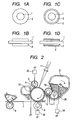
- FIG. 1A illustrates a section in a direction perpendicular to the axis of a conductive roller according to the present invention
- FIG. 1B illustrates a section in the axial direction.
- the conductive member is formed of a conductive support 1 and an elastic layer 2 formed on its outer periphery.
- the support 1 has conductivity and supports the conductive elastic layer to be provided thereon.
- Metals such as iron, aluminum, titanium, copper, and nickel, and alloys thereof can be given as examples of a material for the support.
- the elastic layer 2 contains an A-B-A type block copolymer constituted of two kinds of polymer blocks, i.e., a non-ion conducting block (hereinafter referred to as "A block”) and an ion conducting block having an ion exchange group (hereinafter referred to as "B block”).
- a block non-ion conducting block
- B block ion conducting block having an ion exchange group
- the block copolymer is a thermoplastic elastomer
- the A block forms any structure selected from the group consisting of a spherical structure, a cylindrical structure, and a bicontinuous structure
- the B block forms a matrix for the structure.
- the A-B-A type block copolymer according to the present invention shows ionic conductivity because the copolymer has the ion exchange group in the ion conducting block. Further, the ion exchange group is directly bonded to the main chain of a molecule of the ion conducting block through a covalent bond. Accordingly, the movement of the ion exchange group in the elastic layer when a DC voltage is applied to the conductive member over a long time period is restricted, and hence an increase in electrical resistance of the conductive member over time can be suppressed.
- the amount of the ion conducting material that dissolves in the binder rubber is determined by the kinds of the binder rubber and the ion conducting agent, and hence the ion conducting agent does not dissolve in more than its saturated dissolution amount.
- the ion conducting agent when the ion conducting agent is added in more than its saturated dissolution amount to the binder rubber, molecules of the ion conducting agent merely aggregate and hence a resistance value that can be achieved by the conductive roller is limited in some cases.
- the A-B-A type block copolymer having, in a molecule thereof, the B block formed of a polymer block having an ion exchange group is used as a binder like the present invention, aggregation in association with an increase in its addition amount does not occur in the elastic layer.
- the ion exchange group which the B block according to the present invention has include a sulfonic group (-SO 3 H), a carboxyl group, a phosphate group (H 2 PO 4 -), and a phosphite group.
- a sulfonic group, a phosphate group, or a carboxyl group is preferred because high conductivity can be imparted to the elastic layer.
- a sulfonic group is particularly suitably used.
- the electrical resistance value of the elastic layer can be adjusted to fall within the range of 1 ⁇ 10 2 to 1 ⁇ 10 11 ⁇ cm, which are desirable electrical resistance values upon its use in the conductive member, depending on the content of the ion exchange group bonded to the B block.
- the amount of the ion exchange group with respect to the ion conducting block for adjusting the electrical resistance value within the range is 10 to 30 mol%, preferably 15 to 25 mol%.
- the introduction amount of the ion exchange group can be easily measured by employing proton NMR.
- a method of introducing the ion exchange group is as described below.
- the ion exchange group is a sulfonic group and the main chain of the ion conducting block is a diene-based polymer
- a dichloromethane solution of the block copolymer is prepared and then sulfuric acid is added to the solution.
- a sulfonic group can be selectively introduced into a double bond by doing so.
- the A-B-A type block copolymer of the present invention needs to serve as a thermoplastic elastomer to show rubber elasticity. Accordingly, the glass transition temperature of the ion conducting block as the B block is 10°C or less, preferably 0°C or less.
- Examples of the B block that satisfies the above-mentioned conditions include the following polymers: a polybutadiene, a polyisoprene, a polyethylene-butadiene, a polyethylene-propylene, a polyisobutylene, a polyacrylic acid, a maleic acid-modified polyethylene-butylene (M-PEB), a maleic acid-modified polyethylene-propylene (M-PEP), a maleic acid-modified polyethylene-ethylene-propylene (M-PEEP), and a maleic acid-modified polyisobutylene.
- M-PEB maleic acid-modified polyethylene-butylene
- M-PEP maleic acid-modified polyethylene-propylene
- M-PEEP maleic acid-modified polyethylene-ethylene-propylene
- the B block preferably has at least one constitutional unit selected from the group consisting of constitutional units represented by the following formulae (1) to (3):
- X's each independently represent a hydroxyl group (-OH) or a sulfonic group (-SO 3 H)
- Y's each independently represent a hydroxyl group or a sulfonic group
- Z's each independently represent a hydrogen atom or a methyl group, provided that when X represents a sulfonic group, Y represents a hydroxyl group, and when X represents a hydroxyl group, Y represents a sulfonic group.
- the B block preferably has at least one constitutional unit selected from the group consisting of constitutional units represented by the following formulae (4) to (6):
- X's each independently represent a carboxyl group or a hydrogen atom
- Y's each independently represent a carboxyl group or a hydrogen atom
- Z's each independently represent a hydrogen atom or a methyl group, provided that when X represents a carboxyl group, Y represents a hydrogen atom, and when X represents a hydrogen atom, Y represents a carboxyl group or a hydrogen atom.
- the B block is preferably a linear polymer block having constitutional units represented by the following formula (7) and the following formula (8):
- R represents a divalent, saturated hydrocarbon group having 2 or more and 4 or less carbon atoms.
- the A block in the A-B-A type block copolymer according to the present invention is a non-ion conducting block.
- the A block serves as a crosslinking point of the thermoplastic elastomer constituted of the A-B-A type block copolymer according to the present invention.
- a phase having any one of a spherical structure, a cylindrical structure, and a bicontinuous structure, the structure being formed of the A block to serve as a crosslinking point is microscopically dispersed in a matrix phase constituted of the B block.
- the strength of the elastic layer increases and hence the occurrence of irreversible deformation of the elastic layer, i.e., compression set is effectively suppressed.
- the A block according to the present invention is preferably a block capable of constituting a polymer that hardly deforms even at normal temperature.
- the melting point or glass transition temperature of the block is preferably higher than room temperature.
- Such A block is preferably, for example, at least one constitutional unit selected from the group consisting of constitutional units represented by the following formulae (9) to (11).
- the A-B-A type block copolymer according to the present invention constituted of the A block and the B block as described above undergoes a phase separation as a result of the following.
- a repulsive interaction acts between the A block and the B block as dissimilar polymers, and polymer chains of the same kind agglomerate.
- the copolymer cannot produce a phase-separated structure larger than the spread of each polymer chain owing to connectivity between the dissimilar polymer chains.
- the copolymer produces a periodic self-assembled structure of several nanometers to several hundreds of nanometers.
- microphase-separated structure Such structure is referred to as "microphase-separated structure.”
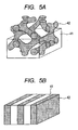
- FIGS. 4A, 4B , 5A, and 5B each show a schematic view of the microphase-separated structure formed by the A-B-A type block copolymer according to the present invention.
- reference numeral 41 represents a matrix phase formed of the B block and reference numeral 42 represents a phase formed of the A block.
- FIG. 4A illustrates such a microphase-separated structure that the phase formed of the A block has a spherical structure
- FIG. 4B illustrates such a microphase-separated structure that the phase formed of the A block has a cylindrical structure.
- FIG. 5A illustrates such a microphase-separated structure that the phase formed of the A block has a bicontinuous structure.
- FIG. 5B illustrates such a microphase-separated structure that the phase formed of the A block has a lamellar structure.
- the microphase-separated structure of the block copolymer can be identified by directly observing the structure with a transmission electron microscope (TEM) or by performing crystallography based on small-angle X-ray scattering (SAXS) measurement.
- TEM transmission electron microscope
- SAXS small-angle X-ray scattering
- the A-B-A type block copolymer to be used in the present invention is observed as described below when a hydrophilic stain such as phosphotungstic acid is used because the B block having the ion exchange group is hydrophilic and the A block as the non-ion conducting block is hydrophobic. That is, the B block is relatively dimly observed and the A block is relatively brightly observed at the time of the observation with the TEM. Accordingly, it can be recognized that such a microphase-separated structure that the B block has a phase having any one of the spherical structure, the cylindrical structure, and the bicontinuous structure is formed, and the A block is a continuous phase.
- the A-B-A type block copolymer constitutes a microphase-separated structure formed by the presence of the phase formed of the A block having a spherical structure, a cylindrical structure, or a spherical structure, the structure being illustrated in FIG. 4A, FIG. 4B , or FIG. 5A , in a continuous phase formed of the B block that contributes to ionic conduction.
- the elastic layer according to the present invention shows good conductivity.
- the molecular weight of the A-B-A type block copolymer is not particularly limited under such a condition that the microphase-separated structure is formed. It should be noted that the molecular weight is desirably 10,000 or more here because the film strength of the elastic layer increases as the molecular weight becomes higher.
- the block copolymer is synthesized by a living polymerization method, the molecular weight distribution of the polymer itself is so narrow that nearly no low-molecular weight oligomer or polymer is produced and such oligomer or polymer does not contribute to a variation in electrical resistance of the elastic layer.
- a filler, a softening agent, a processing aid, a tackifier, a dispersant, a foaming agent, or the like which has been generally used as a compounding agent for rubber can be added to the A-B-A type block copolymer of the present invention as required to such an extent that an effect of the invention is not remarkably impaired.
- an additional elastic layer, conductive elastic surface layer (see FIG. 1C and FIG. 1D ), or protective layer can be formed on the outer periphery of the elastic layer depending on purposes.
- the substitution amount of the ion exchange group is preferably such an amount that the volume resistivity of the elastic layer falls within a moderate resistance region (the volume resistivity is 1 ⁇ 10 2 to 1 ⁇ 10 11 ⁇ cm) in each of the following three environments:
- a method of molding the elastic layer is, for example, a known method such as extrusion molding, injection molding, or compression molding. That is, a method involving molding the thermoplastic elastomer into an arbitrary shape through heating and cooling the elastomer to form the elastic layer is available.
- the elastic layer may be produced by directly molding the thermoplastic elastomer on the conductive support, or the conductive support may be covered with the thermoplastic elastomer molded into a tube shape. It should be noted that the shape of the elastic layer may be put in order by polishing its surface after its production.
- the shape of the elastic layer is preferably such that the shape at the central portion on the electrophotographic photosensitive member side of a conductive member for electrophotography is convexed toward the electrophotographic photosensitive member side with respect to an end portion thereof in order that an abutting nip width between the resultant charging member and the electrophotographic photosensitive member may be as uniform as possible in a distribution in the lengthwise direction of the charging member.
- the shape of the conductive member for electrophotography is a roller shape, such a crown shape that the diameter at the central portion of the roller is larger than the diameter at an end portion thereof is preferred.
- the run-out of the resultant conductive member for electrophotography is preferably as small as possible in order that the abutting nip width of the conductive member for electrophotography may be uniform.
- the electrical resistance of the conductive member for electrophotography is preferably 1 ⁇ 10 4 ⁇ or more in the H/H environment, and is preferably 1 ⁇ 10 8 ⁇ or less in the L/L environment.
- the electrical resistance is preferably 2 ⁇ 10 4 ⁇ or more and 6 ⁇ 10 7 ⁇ or less in the N/N environment.
- the electrical resistance in the L/L environment is preferably set to the value or less because a voltage drop in the conductive member for electrophotography is suppressed and hence the electrophotographic photosensitive member can be uniformly charged to a desired value.
- the resistance in the high-temperature, high-humidity environment preferably exceeds the range because even when the electrophotographic photosensitive member is shaved to expose its substrate metal, no applied current leaks and hence no density unevenness due to charging appears on a halftone image.
- the conductive member for electrophotography is not of a roller shape, its resistance is represented in the unit of ⁇ /cm 2 . In that case, the resistance is determined by depositing a 1-cm 2 metal electrode from the vapor onto the surface of the charging member for electrophotography, applying a voltage, and measuring a current that flows as a result of the application.
- FIG. 2 illustrates an electrophotographic image-forming apparatus using, as a charging roller 6, a charging member as one embodiment of the conductive member according to the present invention.
- An electrophotographic photosensitive drum 5 as an image-bearing member is subjected to primary charging by the charging roller 6 while rotating in the direction indicated by an arrow.
- an electrostatic latent image is formed on the drum by exposure light 11 from exposing means (not shown). While a developer in a developer container 31 is charged by being rubbed between a developing roller 12 and a developing blade 30, the developing roller 12 carries the developer on its surface and then the developer is conveyed to the surface of the electrophotographic photosensitive drum 5. As a result, the electrostatic latent image is developed and hence a toner image is formed.
- the toner image is transferred onto a recording medium 7 in a gap between a transfer roller 8 and the electrophotographic photosensitive drum 5, and is then fixed in a fixing portion 9.
- Toner remaining on the surface of the electrophotographic photosensitive member 5 without being transferred is recovered by a cleaning blade 10. Voltages are applied to, for example, the developing roller 12, the charging roller 6, and the transfer roller 8 from power supplies 18, 20, and 22 of the image-forming apparatus, respectively.
- a DC voltage is applied from the power supply 20 to the charging roller 6.
- the use of the DC voltage as an applied voltage has an advantage in that a cost for the power supply can be suppressed to a low level.
- the use has an advantage in that no charging sound is generated.
- the absolute value for the DC voltage to be applied is preferably the sum of the breakdown voltage of air and the primary charging potential of the surface of the body to be charged (the surface of the electrophotographic photosensitive member).
- a primary charging voltage is preferably set to 900 to 1,500 V because the breakdown voltage of air is about 600 to 700 V and the primary charging potential of the surface of the electrophotographic photosensitive member is about 300 to 800 V in ordinary cases.
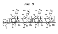
- the electrophotographic image-forming apparatus may be a color electrophotographic image-forming apparatus provided with four colors' worth of members needed for image formation as illustrated in FIG. 3 .
- toner images are transferred between an electrophotographic photosensitive drum 5d and a transfer roller 8d, between an electrophotographic photosensitive drum 5c and a transfer roller 8c, between an electrophotographic photosensitive drum 5b and a transfer roller 8b, and between an electrophotographic photosensitive drum 5a and a transfer roller 8a in the stated order.
- the toner images transferred onto the recording medium 7 are fixed in the fixing portion 9.
- Charging rollers 6a, 6b, 6c, and 6d charge the electrophotographic photosensitive drums 5a, 5b, 5c, and 5d, respectively.
- Four color toners i.e., cyan, yellow, magenta, and black toners are typically used for forming a color electrophotographic image.
- the four color toners may be transferred onto the recording medium 7 in an arbitrary order.
- FIG. 8 is a schematic sectional view of a process cartridge obtained by applying the conductive member for electrophotography according to the present invention to the charging roller 302.
- the process cartridge according to the present invention is such that the electrophotographic photosensitive member 301, the charging roller 302, the developing apparatus 303, the cleaning apparatus 307, and the like are integrated, and is removably (detachably) mounted onto the main body of the electrophotographic apparatus.
- the conductive member according to the present invention is described in more detail by way of examples. It should be noted that a method of measuring the electrical resistance of a conductive roller according to each of the examples and comparative examples, and a method of measuring the surface roughness thereof are as described below.
- Measured is the resistance of the conductive roller when the roller is energized by being brought into abutment with a columnar metal 32 having the same curvature as that of an electrophotographic photosensitive member with the same stress as that in a use state when the photosensitive member is used in an electrophotographic apparatus as illustrated in FIGS. 6A and 6B .
- bearings 33a and 33b are fixed to dead weights, and apply, to both ends of the conductive support 1 of a conductive base layer member 40, stresses for pressing the member vertically downward. Placed in the vertically downward direction of the conductive base layer member 40 is the columnar metal 32 parallel to the conductive base layer member 40.
- the conductive base layer member 40 is pressed against the columnar metal 32 with the bearings 33a and 33b as illustrated in FIG. 6B while the columnar metal 32 is rotated by a driving apparatus (not shown). While the columnar metal 32 is rotated at the same rotational speed as that of the electrophotographic photosensitive drum in its use state to cause the conductive base layer member 40 to rotate in association with the rotation, a DC voltage of -200 V is applied from a power supply 34 and then a current flowing out of the columnar metal 32 is measured with an ammeter A. The electrical resistance of the conductive base layer member 40 is calculated from the applied voltage at this time and the measured current.
- the member 40 was brought into abutment with the columnar metal 32 having a diameter of 30 mm by applying a force of 5 N to each of both ends of the conductive support 1, and then the columnar metal 32 was rotated at a circumferential speed of 150 mm/sec.
- the surface roughness of the conductive base layer is preferably 50 ⁇ m or less, particularly preferably 30 ⁇ m or less, more preferably 20 ⁇ m or less in terms of ten-point average roughness (Rz jis 1994).
- a surface roughness-measuring apparatus (trade name: SURFCORDER SE3500, manufactured by Kosaka Laboratory Ltd.) was used in the measurement of the surface roughness and a contact needle made of diamond having a tip radius of 2 ⁇ m was also used. Measurement conditions were based on JIS B0601:1994, a measuring speed was set to 0.5 mm/sec, a cut-off frequency ⁇ c was set to 0.8 mm, a reference length was set to 0.8 mm, and an evaluation length was set to 8.0 mm.
- a polymer No. 1 was synthesized by a living anion polymerization method.
- a pressure-resistant container having a volume of 10 L was prepared and air in the pressure-resistant container was replaced with dry argon.
- 8.46 g of a styrene monomer purified with molecular sieves, 1.0 L of cyclohexane as a polymerization solvent purified with molecular sieves, and 0.80 g of a 10-wt% hexane solution of sec-butyllithium as an initiator were added to the container.
- the terpolymer is represented as "styrene-butadiene/isoprene-styrene" in Table 1-2 below.
- the resultant terpolymer had a mass-average molecular weight Mw by gel permeation chromatography (GPC) of 8.0 ⁇ 10 4 .
- the terpolymer is defined as the polymer No. 1.
- Table 1-2 shows a volume ratio among the styrene block, block obtained by the random copolymerization of butadiene and isoprene, and styrene block of the polymer No. 1. In addition, Table 1-2 also shows a volume ratio between butadiene and isoprene in the block obtained by the random copolymerization of butadiene and isoprene.
- Polymers Nos. 2 to 13 and a polymer No. 19 were each synthesized in the same manner as in the polymer No. 1 except that the blending quantities of the raw materials and the initiator were changed as shown in Table 1-1.
- Table 1-2 shows the weight-average molecular weight of each of the resultant polymers, a volume ratio among the respective blocks thereof, and a volume ratio between butadiene and isoprene in the block obtained by the random copolymerization of butadiene and isoprene.
- Table 1-1 Polymer No.
- Blending quantity (g) 10-Wt% solution of initiator Styrene (first time) Butadiene Isoprene Styrene (second time) 1 0.80 8.46 41.08 42.00 8.46 2 0.80 16.54 33.09 33.82 16.54 3 0.80 19.94 29.73 30.39 19.94 4 0.43 8.46 41.08 42.00 8.46 5 1.60 8.46 41.08 42.00 8.46 6 0.80 8.54 82.93 0.00 8.54 7 0.80 16.67 66.67 0.00 16.67 8 0.80 20.07 59.86 0.00 20.07 9 0.80 8.38 0.00 83.24 8.38 10 0.80 16.42 0.00 67.15 16.42 11 0.80 19.81 0.00 60.39 19.81 12 0.80 8.41 16.34 66.83 8.41 13 0.80 8.51 66.10 16.89 8.51 19 0.80 43.37 6.56 6.71 43.37 Table 1-2 Polymer No.
- a polymer No. 14 was synthesized by a living radical polymerization method.
- a deprotection reaction for a tert-butyl group of the PtBA segment was performed by mixing the resultant block copolymer with 400 g of trifluoroacetic acid in chloroform at room temperature, thereby transforming the segment into a carboxylic acid.
- a PMMA-b-polyacrylic acid (PAA)-b-PMMA triblock copolymer was obtained.
- the resultant triblock copolymer had a mass-average molecular weight by GPC of 4.0 ⁇ 10 4 .
- the copolymer was defined as the polymer No. 14.
- Polymers Nos. 15 to 18 and 20 were each synthesized in the same manner as in the polymer No. 14 except that the blending quantities of the raw materials and the initiator were changed as shown in Table 2-1.
- Table 2-1 shows the weight-average molecular weight Mw of each of the resultant polymers and a volume ratio among the respective blocks thereof.
- Blending quantity (g) Amount of resultant polymer (g) tert-Butyl acrylate Copper bromide Hexamethyltriethylenetetramine Dimethyl-2,6-dibromoheptane dioate Methyl methacrylate First time Second time First time Second time 14 90.23 0.28 0.45 0.675 9.770 0.060 0.10 60.50 15 79.17 0.28 0.45 0.675 20.830 0.060 0.10 65.34 16 73.92 0.28 0.45 0.675 26.080 0.060 0.10 67.64 17 90.23 0.14 0.23 0.337 9.770 0.030 0.05 60.50 18 90.23 0.56 0.90 1.350 9.770 0.120 0.20 60.50 20 36.51 0.28 0.45 0.675 63.490 0.060 0.10 84.02 Table 2-2 Polymer No.
- the dried reaction product was dissolved in 1.0 L of toluene, and then the solution was subjected to dry distillation at a temperature of 120°C while being stirred in a nitrogen atmosphere. During the dry distillation, 500 g of p-toluenesulfonylhydrazine were added to the solution to perform a reaction for 4 hours. Thus, a double bond derived from diene was hydrogenated.
- thermoplastic elastomer No. 1 according to Example 1 was obtained.
- thermoplastic elastomer No. 1 The sulfonation ratio of the thermoplastic elastomer No. 1 was measured by proton NMR. As a result, it was found that 20 mol% of a sulfonic group was introduced to a double bond of a diene block.
- thermoplastic elastomer No. 1 was cut out with a cryosectioning apparatus (trade name: Cryoultramicrotome, manufactured by Leica Microsystems) and then subjected to steam staining with ruthenium tetroxide.
- the ultrathin section was observed with a transmission electron microscope (TEM). As a result, it was confirmed that a polystyrene block component formed a spherical microphase-separated structure.
- thermoplastic elastomer No. 1 was set in a transfer die in which a tubular die having a maximum inner diameter of 8.6 mm and a crown of 150 ⁇ m with a cored bar (diameter: 6 mm, length: 252 mm, made of SUM22, electroless nickel plating: 6 ⁇ m) set in its central portion had been set. Then, the elastomer was molded with a pressing machine having a temperature of 240°C and then cooled to room temperature with a cold press. After that, the resultant roller was taken out of the transfer die. Thus, a conductive roller No. 1 having a crown shape with a diameter at an end portion of 8.40 mm and a diameter at the central portion of 8.55 mm was obtained.
- the conductive roller No. 1 was left to stand in the N/N environment for 24 hours. After that, its microhardness was measured with a microrubber hardness meter (trade name: MD-1 capa Type A, manufactured by KOBUNSHI KEIKI CO., LTD.).
- the surface roughness (Rzjis) of the conductive roller No. 1 was measured by the method described in the foregoing.
- the electrical resistance value of the conductive roller No. 1 was calculated by the method described in the foregoing.
- An electrophotographic laser printer capable of outputting a recording medium at a speed of 160 mm/sec and having an image resolution of 1,200 dpi was prepared as an electrophotographic laser printer.
- the electrophotographic laser printer can convey A4-sized paper in its longitudinal direction.
- its electrophotographic photosensitive member is an electrophotographic photosensitive drum according to a reversal development mode obtained by forming an organic photosensitive layer having a thickness of 16 ⁇ m on an aluminum cylinder. It should be noted that the outermost layer of the electrophotographic photosensitive drum is formed of a charge-transporting layer using a modified polyallylate resin as a binder resin.
- the toner of the printer is a polymerized toner having a glass transition temperature of 63°C and a mass-average particle diameter of 6.5 ⁇ m obtained by: polymerizing a random copolymer of styrene and butyl acrylate containing a wax as a main agent, a charge control agent, a dye, and the like; further polymerizing a polyester thin layer on its surface; and externally adding silica fine particles and the like.
- the conductive roller No. 1 was mounted as a charging roller on the electrophotographic laser printer. Then, the electrophotographic laser printer was placed in the N/N environment for 24 hours. After that, image output was performed in the N/N environment.
- Image patterns to be output were five kinds, i.e., (pattern 1) to (pattern 5) shown in Table 3 below.
- Table 3 Pattern No. Kind of image 1 An intermediate image exactly intermediate in charged potential between a blank black image and a blank white image obtained by reducing the quantity of laser light to 35% as compared with that in the case where the blank black image is output.
- the resultant image patterns were visually observed and evaluated for the presence or absence of unevenness resulting from the charging roller on the basis of criteria shown in Table 4 below.
- Table 4 Rank Evaluation criterion A No unevenness is observed in each of all image patterns.
- B Unevenness is observed in an image of the pattern 1. No unevenness is observed in an image of any other pattern.
- C Unevenness is observed in each of images of the pattern 1 and the pattern 2. No unevenness is observed in an image of any other pattern.
- D Unevenness is observed in each of images of the pattern 1, the pattern 2, and the pattern 3. No unevenness is observed in an image of any other pattern.
- E Unevenness is observed in an image of any pattern except the pattern 5.
- F Unevenness is observed in each of all image patterns.
- the term "intermittent mode" as used in this evaluation means that an operation in which the printer is stopped after the output of only one electrophotographic image from a state where the printer is stopped is repeated. That is, in the intermittent mode, the electrophotographic photosensitive member repeats the operations of an idle rotation, the output of an electrophotographic image, an idle rotation, and a stop. Therefore, the operation of outputting one electrophotographic image and the operation of stopping the electrophotographic photosensitive member are alternately repeated 15,000 times each.
- the charging roller as an object to be evaluated was taken out and then its surface was washed by being sprayed with high-pressure ion-exchanged water with a high-pressure water washing machine. Next, high-pressure dry air was blown on the surface to remove the water.
- the charging roller after the washing was left to stand in the N/N environment for 24 hours and then its electrical resistance was calculated by the same method as that in Evaluation (1).
- Thermoplastic elastomers Nos. 2 to 17 were each synthesized in the same manner as in Example 1 except that in Example 1, the polymer No. 1 was changed to a polymer with a polymer number shown in Table 5-1 and the blending quantity of concentrated sulfuric acid was changed to an amount shown in Table 5-1.
- the introduction ratio of a sulfonic group with respect to a double bond of a diene block was determined for each of the resultant thermoplastic elastomers Nos. 2 to 17 in the same manner as in Example 1 by employing proton NMR.
- thermoplastic elastomers Nos. 2 to 17 were observed in the same manner as in Example 1.
- Table 5-2 shows the composition of each of the thermoplastic elastomers Nos. 1 to 17 each serving as the A-B-A type copolymer of the present invention, the kind of microphase-separated structure constituted of the polystyrene block of each elastomer, and the introduction ratio of a sulfonic group with respect to a double bond of the diene block of each elastomer.
- conductive rollers Nos. 2 to 17 were produced in the same manner as in Example 1 by using the thermoplastic elastomers Nos. 2 to 17 and then subjected to Evaluations (1) to (6). Table 5-3 shows the results.
- a sulfonic group was introduced to the polymer No. 1 in the same manner as in Example 1 except that the blending quantity of concentrated sulfuric acid in Example 1 was changed to 27.52 g.
- 1.0 L of methanol was dropped into the reaction solution to stop the reaction.
- the resultant reaction product was washed by repeating each of dissolution in toluene and reprecipitation with methanol three times. After the washing, the reaction product was dried in the air at 80°C for 24 hours. Next, the dried reaction product was dissolved in 1 L of toluene and then 200 g of glacial acetic acid were gradually dropped to the solution while the solution was stirred in a nitrogen atmosphere.
- thermoplastic elastomer No. 18 was obtained.
- the introduction ratio of a carboxyl group with respect to a double bond of a diene block was determined for the thermoplastic elastomer No. 18 in the same manner as in Example 1 by employing proton NMR.
- thermoplastic elastomer No. 18 shows the state of the microphase-separated structure of the thermoplastic elastomer No. 18 in the same manner as in Example 1.
- Table 5-2 shows the composition of the thermoplastic elastomer No. 18 serving as the A-B-A type copolymer of the present invention, the kind of microphase-separated structure constituted of the polystyrene block of the elastomer, and the introduction ratio of a carboxyl group with respect to a double bond of the diene block of the elastomer.
- a conductive roller No. 18 was produced in the same manner as in Example 1 by using the thermoplastic elastomer No. 18 and then subjected to Evaluations (1) to (4). Table 5-3 shows the results.
- Thermoplastic elastomers of Examples 19 and 20 were each obtained in the same manner as in Example 18 except that in Example 18, the polymer No. 1 was changed to a polymer with a polymer number shown in Table 5-1 and the blending quantity of concentrated sulfuric acid was changed to an amount shown in Table 5-1, and in the same manner as in Example 18 except that the compositions of the thermoplastic elastomers Nos. 19 and 20 were changed as described below.
- the introduction ratio of a carboxyl group with respect to a double bond of a diene block was determined for each of the resultant thermoplastic elastomers Nos. 19 and 20 in the same manner as in Example 18 by employing proton NMR.
- thermoplastic elastomers Nos. 19 and 20 were observed in the same manner as in Example 18.
- Table 5-2 shows the composition of each of the thermoplastic elastomers Nos. 19 and 20 each serving as the A-B-A type copolymer of the present invention, the kind of microphase-separated structure constituted of the polystyrene block of each elastomer, and the introduction ratio of a carboxyl group with respect to a double bond of the diene block of each elastomer.
- conductive rollers Nos. 19 and 20 were produced in the same manner as in Example 1 by using the thermoplastic elastomers Nos. 19 and 20 and then subjected to Evaluations (1) to (6).
- Table 5-3 shows the results.
- Table 5-1 Example No. Number of polymer used in synthesis Blending quantity of concentrated sulfuric acid (g) 2 2 22.17 3 3 19.92 4 4 27.52 5 5 27.52 6 6 30.66 7 7 24.65 8 8 22.13 9 9 24.44 10 10 19.72 11 11 17.73 12 12 25.66 13 13 29.4 14 1 13.76 15 1 20.64 16 1 34.4 17 1 41.28 18 1 27.52 19 6 22.13 20 9 24.44
- Table 5-2 Example Thermoplastic elastomer No.
- Type of structure of A block in microphase-separated structure Composition of A-B-A type block copolymer A block B block Introduction ratio of ion exchange group Constitutional unit Volume fraction (%) Constitutional unit Volume fraction (%) (Mol%) 1 1 Spherical Styrene 15 Butadiene/isoprene 85 20 2 2 Cylindrical Styrene 30 Butadiene/isoprene 70 20 3 3 Bicontinuous Styrene 36.5 Butadiene/isoprene 63.5 20 4 4 Spherical Styrene 15 Butadiene/isoprene 85 20 5 5 Spherical Styrene 15 Butadiene/isoprene 85 20 6 6 Spherical Styrene 15 Butadiene 85 20 7 7 Cylindrical Styrene 30 Butadiene 70 20 8 8 Bicontinuous Styrene 36.5 Butadiene 63.5 20 9 9 Spherical Styrene 15 Isoprene 85 20 10 10 Cylindrical Styrene 30 I
- thermoplastic elastomer No. 21 formed of a triblock copolymer having a PMMA at each of both terminals of the sulfonic group-containing segment was obtained.
- thermoplastic elastomer No. 21 The introduction ratio of a sulfonic group with respect to the carboxyl group of the acrylic acid block was determined for the thermoplastic elastomer No. 21 in the same manner as in Example 1 by employing proton NMR.
- thermoplastic elastomer No. 21 shows the state of the microphase-separated structure of the thermoplastic elastomer No. 21 in the same manner as in Example 1.
- Table 6-2 shows the composition of the thermoplastic elastomer No. 21 serving as the A-B-A type copolymer of the present invention, the kind of microphase-separated structure constituted of the methyl methacrylate block of the elastomer, and the introduction ratio of a sulfonic group with respect to the carboxyl group of the acrylic acid block of the elastomer.
- a conductive roller No. 21 was produced in the same manner as in Example 1 by using the thermoplastic elastomer No. 21 and then subjected to Evaluations (1) to (6). Table 6-3 shows the results.
- Thermoplastic elastomers Nos. 22 to 33 were each synthesized in the same manner as in Example 21 except that in Example 21, the polymer used in the synthesis and its blending quantity, and the blending quantity of the sultone represented by the formula (12) were changed as shown in Table 6-1.
- the introduction ratio of a sulfonic group with respect to the carboxyl group of the acrylic acid block was determined for the thermoplastic elastomer Nos. 22 to 33 in the same manner as in Example 1 by employing proton NMR.
- thermoplastic elastomer Nos. 22 to 33 shows the state of the microphase-separated structure of the thermoplastic elastomer Nos. 22 to 33 observed in the same manner as in Example 1.
- Table 6-2 shows the composition of the thermoplastic elastomer Nos. 22 to 33 serving as the A-B-A type copolymer of the present invention, the kind of microphase-separated structure constituted of the methyl methacrylate block of the elastomer, and the introduction ratio of a sulfonic group with respect to the carboxyl group of the acrylic acid block of the elastomer.
- a conductive roller Nos. 22 to 33 was produced in the same manner as in Example 1 by using the thermoplastic elastomer Nos. 22 to 33 and then subjected to Evaluations (1) to (6).
- Table 6-3 shows the results.
- Table 6-1 Example No. Polymer used in synthesis Sultone No.
- Blending quantity (g) Kind Blending quantity (g) 22 15 65.34 Formula (12) 15.09 23 16 67.64 Formula (12) 14.09 24 17 60.60 Formula (12) 17.93 25 18 60.50 Formula (13) 17.93 26 14 60.50 Formula (13) 15.22 27 14 60.50 Formula (14) 16.91 28 14 60.50 Formula (15) 19.17 29 14 60.50 Formula (16) 19.17 30 14 60.50 Formula (12) 8.60 31 14 60.50 Formula I (12) 12.90 32 14 60.50 Formula (12) 21.50 33 14 60.50 Formula (12) 25.79
- a conductive tube having an outer diameter of 8.5 mm and a wall thickness of 0.40 mm was produced with the thermoplastic elastomer No. 17.
- the conductive member of Example 14 was covered with the resultant conductive tube while the tube was inflated with an air pressure. Thus, a conductive elastic body surface layer was produced.
- a conductive roller No. 34 was produced by cutting and evening the end portions of the tube, and was then subjected to Evaluations (1) to (6).
- a conductive roller No. 35 was produced in the same manner as in Example 34 except that the thermoplastic elastomer No. 14 was used, and was then subjected to Evaluations (1) to (6).
- a conductive roller No. 36 and a conductive roller No. 37 were produced in the same manner as in the conductive roller No. 1 and the conductive roller No. 35, respectively, and were then subjected to Evaluation (7) below.
- the conductive roller No. 36 and the conductive roller No. 37 were each mounted as a developing roller for the electrophotographic laser printer used in Evaluation (4). After the electrophotographic laser printer had been placed in the N/N environment for 24 hours, image output was performed in the N/N environment. Image patterns to be output were the five kinds, i.e., (pattern 1) to (pattern 5) shown in Table 3. The resultant images were evaluated for the presence or absence of unevenness resulting from the developing roller on the basis of the criteria shown in Table 4.
- Electrophotographic images were output in the same manner as in Evaluation (5) with the electrophotographic laser printer used in Evaluation (7). Subsequently, the five kinds of image patterns shown in Table 3 were output and then the respective images were evaluated on the basis of the criteria shown in Table 4.
- each conductive roller was taken out of the laser printer, its electrical resistance value was calculated, and a variation ratio with respect to its initial electrical resistance value was calculated.
- Table 6-3 shows the results of the evaluations of the conductive rollers Nos. 21 to 37.
- Table 6-3 Example Conductive roller No. Evaluation (1) Evaluation (2) Evaluation for electrical resistance value Image evaluation Evaluation (3) Evaluation (6) Evaluation (9) Variation ratio of electrical resistance value Evaluation (4) Evaluation (5) Evaluation (7) Evaluation (8) (°) ( ⁇ m) ( ⁇ ) ( ⁇ ) ( ⁇ ) 21 21 62 2.4 483,870 488,225 - 1% A A - - 22 22 68 2.5 707,547 711,792 - 1% A A - - 23 23 70 2.3 986,842 990,789 - 0% A A - - 24 24 63 2.6 555,555 561,666 - 1% A A - - 25 25 61 2.7 454,545 458,181 - 1% A A - - 26 26 61 2.6 471,698 475,943 - 1% A A - - 27 27 62 2.3 496,688 501,158 - 1% A
- Thermoplastic elastomers Nos. 38 to 40 were each synthesized in the same manner as in the thermoplastic elastomer No. 1 except that in the synthesis of the thermoplastic elastomer No. 1 in Example 1, concentrated sulfuric acid was changed to a compound shown in Table 7-1 and its blending quantity was set to an amount shown in Table 7-1.
- the introduction ratio of a phosphonic acid group with respect to a double bond of a diene block (Examples 38 and 39) and the introduction ratio of a carboxyl group with respect to a double bond of a diene block (Example 40) were determined for the resultant thermoplastic elastomers Nos. 38 to 40, respectively in the same manner as in Example 1 by employing proton NMR.
- thermoplastic elastomer Nos. 38 to 40 the state of the microphase-separated structure of the thermoplastic elastomer Nos. 38 to 40 was observed in the same manner as in Example 1.
- Table 7-2 shows the composition of the thermoplastic elastomer Nos. 38 to 40 serving as the A-B-A type copolymer of the present invention, the kind of microphase-separated structure constituted of the polystyrene block of the elastomer, and the introduction ratio of a phosphonic acid group with respect to a double bond of a diene block or the introduction ratio of a carboxyl group with respect to a double bond of a diene block of the elastomer.
- a conductive roller Nos. 38 to 40 was produced in the same manner as in Example 1 by using the thermoplastic elastomer Nos. 38 to 40 and then subjected to Evaluations (1) to (6).
- Table 7-3 shows the results.
- Table 7-1 Example No. Compound Blending quantity (g) 38 Phosphoric acid 53.94 39 Phosphoric acid 94.40 40 Glacial acetic acid 200.00
- thermoplastic elastomer No. 41 The introduction ratio of a phosphonic acid group with respect to the carboxyl group of the acrylic acid block was determined for the thermoplastic elastomer No. 41 in the same manner as in Example 1 by employing proton NMR.
- thermoplastic elastomer No. 41 shows the state of the microphase-separated structure of the thermoplastic elastomer No. 41 in the same manner as in Example 1.
- Table 7-2 shows the composition of the thermoplastic elastomer No. 41 serving as the A-B-A type copolymer of the present invention, the kind of microphase-separated structure constituted of the methyl methacrylate block of the elastomer, and the introduction ratio of a phosphonic acid group with respect to the carboxyl group of the acrylic acid block of the elastomer.
- a conductive roller No. 41 was produced in the same manner as in Example 1 by using the thermoplastic elastomer No. 41 and then subjected to Evaluations (1) to (6). Table 7-3 shows the results.
- thermoplastic elastomer No. 42 was obtained in the same manner as in Example 41 except that in Example 41, the blending quantity of 2-aminobenzenesulfonic acid was changed to 85.34 g and the blending quantity of triphenyl phosphite was changed to 305.80 g.
- thermoplastic elastomer No. 42 The introduction ratio of a phosphonic acid group with respect to the carboxyl group of the acrylic acid block was determined for the thermoplastic elastomer No. 42 in the same manner as in Example 1 by employing proton NMR.
- thermoplastic elastomer No. 42 shows the state of the microphase-separated structure of the thermoplastic elastomer No. 42 in the same manner as in Example 1.
- Table 7-2 shows the composition of the thermoplastic elastomer No. 42 serving as the A-B-A type copolymer of the present invention, the kind of microphase-separated structure constituted of the methyl methacrylate block of the elastomer, and the introduction ratio of a phosphonic acid group with respect to the carboxyl group of the acrylic acid block of the elastomer.
- a conductive roller No. 42 was produced in the same manner as in Example 1 by using the thermoplastic elastomer No. 42 and then subjected to Evaluations (1) to (6). Table 7-3 shows the results.
- the polymer No. 14 was prepared as a thermoplastic elastomer No. 43.
- the state of the microphase-separated structure of the thermoplastic elastomer No. 43 was observed in the same manner as in Example 1.
- Table 7-2 shows the composition of the thermoplastic elastomer No. 43 serving as the A-B-A type copolymer of the present invention and the kind of microphase-separated structure constituted of the methyl methacrylate block of the elastomer. It should be noted that in this example, the introduction ratio of an ion exchange group in Table 7-2 was set to 0% because the carboxyl group which the acrylic acid block constituting the B block of the polymer No. 14 had was not substituted with any other ion exchange group.
- a conductive roller No. 43 was produced in the same manner as in Example 1 by using the thermoplastic elastomer No. 43 and then subjected to Evaluations (1) to (6).
- Table 7-3 shows the results.
- Table 7-2 Example Thermoplastic elastomer No.
- Type of structure of A block in microphase-separated structure Composition of A-B-A type block copolymer A block B block Introduction ratio of ion exchange group Material Volume fraction (%) Material Volume fraction (%) (Mol%) 38 38 Spherical Styrene 15 Butadiene/isopr ene 85 40 39 39 Spherical Styrene 15 Butadiene/isopr ene 85 70 40 40 Spherical Styrene 15 Butadiene/isopr ene 85 100 41 41 Spherical Methyl methacrylate 15 Acrylic acid 85 40 42 42 Spherical Methyl methacrylate 15 Acrylic acid 85 70 43 43 Spherical Methyl methacrylate 15 Acrylic acid 85 100 Table 7-3 Example Evaluation (1) Evaluation (2) Evaluation for electrical resistance value Image evaluation Evaluation (3) Evaluation (6) Variation ratio of electrical resistance value Evaluation (4) Evaluation (5) (°) ( ⁇ m) ( ⁇ ) ( ⁇ ) 38 62 2.5 428,571 443,142 3% B (Horizontal streak) C (Horiz
- a hydrin rubber containing 1 part of trimethyl octyl ammonium perchlorate was subjected to vulcanization molding in a die.
- a conductive roller No. C-1 having the same shape as that of Example 1 was obtained.
- the roller was subjected to Evaluations (1) to (6).
- Table 8-2 shows the results.
- thermoplastic urethane elastomer containing 1 part of trimethyl octyl ammonium perchlorate was subjected to molding in a die.
- a conductive roller No. C-3 having the same shape as that of Example 1 was obtained.
- the roller was subjected to Evaluations (1) to (6).
- Table 8-2 shows the results.
- thermosetting urethane ionomer containing 15 mol% of a sulfonic group was subjected to vulcanization molding in a die.
- a conductive roller No. C-4 having the same shape as that of Example 1 was obtained.
- the roller was subjected to Evaluations (1) to (6).
- Table 8-2 shows the results.
- thermoplastic elastomer No. C-1 was obtained in the same manner as in the thermoplastic elastomer No. 1 except that in the synthesis of the thermoplastic elastomer No. 1 of Example 1, the polymer No. 1 was changed to the polymer No. 19 and the blending quantity of concentrated sulfuric acid was changed to 4.39 g. The introduction ratio of a sulfonic group with respect to a double bond of a diene block was determined for the resultant thermoplastic elastomer No. C-1 in the same manner as in Example 1 by employing proton NMR.
- thermoplastic elastomer No. C-1 the state of the microphase-separated structure of the thermoplastic elastomer No. C-1 was observed in the same manner as in Example 1.
- the diene block component having a sulfonic group formed a spherical microphase-separated structure and a styrene block component served as a matrix for the structure. That is, a B block having an ion exchange group constituted a phase having a spherical structure and an A block as a non-ion conducting block constituted a matrix phase.
- Table 8-1 shows the composition of the thermoplastic elastomer No. C-1 serving as an A-B-A type copolymer, the kind of microphase-separated structure constituted of the styrene block of the elastomer, and the introduction ratio of a sulfonic group with respect to a double bond of the diene block of the elastomer.
- a conductive roller No. C-5 was produced in the same manner as in Example 1 by using the thermoplastic elastomer No. C-1 and then subjected to Evaluations (1) to (6).
- Table 8-2 shows the results.
- thermoplastic elastomer No. C-2 was synthesized in the same manner as in the thermoplastic elastomer No. 21 except that in the synthesis of the thermoplastic elastomer No. 21 of Example 21, the polymer No. 14 was changed to the polymer No. 20, its blending quantity was set to 84.02 g, and the blending quantity of the sultone represented by the formula (12) was changed to 6.96 g.
- thermoplastic elastomer No. C-1 The introduction ratio of a sulfonic group with respect to the carboxyl group of the acrylic acid block was determined for the resultant thermoplastic elastomer No. C-1 in the same manner as in Example 1 by employing proton NMR.
- thermoplastic elastomer No. C-2 the state of the microphase-separated structure of the thermoplastic elastomer No. C-2 was observed in the same manner as in Example 1.
- the thermoplastic elastomer had a microphase-separated structure in which the acrylic acid block having a sulfonic group forms a spherical structure and a methyl methacrylate block constitutes a matrix for the structure. That is, the B block in the present invention constituted a phase having a spherical structure and the A block constituted a matrix phase.
- Table 8-1 shows the composition of the thermoplastic elastomer No. C-2 serving as the A-B-A type copolymer of the present invention, the kind of microphase-separated structure constituted of the polystyrene block of the elastomer, and the introduction ratio of a sulfonic group with respect to a double bond of the diene block of the elastomer.
- a conductive roller No. C-5 was produced in the same manner as in Example 1 by using the thermoplastic elastomer No. C-2 and then subjected to Evaluations (1) to (6).
- Table 8-2 shows the results.
- the polymer No. 1 was prepared as a thermoplastic elastomer No. C-3.
- thermoplastic elastomer No. C-3 The state of the microphase-separated structure of the thermoplastic elastomer No. C-3 was observed in the same manner as in Example 1.
- Table 8-2 shows the composition of the thermoplastic elastomer No. C-3 and the kind of microphase-separated structure of the elastomer. It should be noted that the value "0%" was described in the item of the introduction ratio of an ion exchange group in Table 8-2 because the thermoplastic elastomer No. C-3 was free of any ion exchange group.
- a conductive roller No. 41 was produced in the same manner as in Example 1 by using the thermoplastic elastomer No. C-3 and then subjected to Evaluations (1) to (6).
- the conductive roller No. C-6 was not subjected to Evaluation (5) nor Evaluation (6) because the roller could not exert any function as a charging roller from an initial stage.
- thermoplastic elastomer No. C-4 formed of a PMMA-b-PtBA-b-PMMA triblock copolymer was obtained without the performance of any deprotection reaction for the polymer No. 14.
- thermoplastic elastomer No. C-4 The state of the microphase-separated structure of the thermoplastic elastomer No. C-4 was observed in the same manner as in Example 1.
- Table 8-2 shows the composition of the thermoplastic elastomer No. C-4 and the kind of microphase-separated structure of the elastomer. It should be noted that the value "0%" was described in the item of the introduction ratio of an ion exchange group in Table 8-2 because the thermoplastic elastomer No. C-4 was free of any ion exchange group.
- a conductive roller No. 41 was produced in the same manner as in Example 1 by using the thermoplastic elastomer No. C-4 and then subjected to Evaluations (1) to (6).
- the conductive roller No. C-6 was not subjected to Evaluation (5) nor Evaluation (6) because the roller could not exert any function as a charging roller from an initial stage.
- Table 8-1 Comparative Example Thermoplastic elastomer No.
- Type of structure of A block in microphase-separated structure Composition of A-B-A type block j copolymer A block B block Introduction ratio of ion exchange group Material Volume fraction (%) Material Volume fraction (%) (Mol%) 5 C-1
- a block constitutes matrix phase Styrene 85 Butadiene/ isoprene 15 20 6
- a block constitutes matrix phase Methyl methacrylate 85 Acrylic acid 15 20 7 C-3 *Spherical Styrene 15 Butadiene/ isoprene 85 0 8 C-4 *Spherical Methyl methacrylate 15 Acrylic acid 85 0 Table 8-2 Comparative Example Conductive roller No.
Landscapes
- Physics & Mathematics (AREA)
- General Physics & Mathematics (AREA)
- Engineering & Computer Science (AREA)
- Plasma & Fusion (AREA)
- Chemical & Material Sciences (AREA)
- Medicinal Chemistry (AREA)
- Health & Medical Sciences (AREA)
- Chemical Kinetics & Catalysis (AREA)
- Inorganic Chemistry (AREA)
- Polymers & Plastics (AREA)
- Organic Chemistry (AREA)
- Electrostatic Charge, Transfer And Separation In Electrography (AREA)
- Electrophotography Configuration And Component (AREA)
- Compositions Of Macromolecular Compounds (AREA)
- Dry Development In Electrophotography (AREA)
- Graft Or Block Polymers (AREA)
- Addition Polymer Or Copolymer, Post-Treatments, Or Chemical Modifications (AREA)
Applications Claiming Priority (2)
| Application Number | Priority Date | Filing Date | Title |
|---|---|---|---|
| JP2011082218 | 2011-04-01 | ||
| PCT/JP2012/002065 WO2012137438A1 (ja) | 2011-04-01 | 2012-03-26 | 導電性部材、プロセスカートリッジおよび電子写真装置 |
Publications (3)
| Publication Number | Publication Date |
|---|---|
| EP2696245A1 EP2696245A1 (en) | 2014-02-12 |
| EP2696245A4 EP2696245A4 (en) | 2014-09-10 |
| EP2696245B1 true EP2696245B1 (en) | 2015-08-19 |
Family
ID=46968852
Family Applications (1)
| Application Number | Title | Priority Date | Filing Date |
|---|---|---|---|
| EP12767902.5A Not-in-force EP2696245B1 (en) | 2011-04-01 | 2012-03-26 | Conductive member, process cartridge, and electrophotographic device |
Country Status (6)
| Country | Link |
|---|---|
| US (1) | US20120308261A1 (enExample) |
| EP (1) | EP2696245B1 (enExample) |
| JP (1) | JP5936412B2 (enExample) |
| KR (1) | KR101506834B1 (enExample) |
| CN (1) | CN103492957B (enExample) |
| WO (1) | WO2012137438A1 (enExample) |
Families Citing this family (37)
| Publication number | Priority date | Publication date | Assignee | Title |
|---|---|---|---|---|
| JP5875416B2 (ja) | 2011-03-22 | 2016-03-02 | キヤノン株式会社 | 電子写真用導電性部材 |
| JP6000580B2 (ja) | 2011-03-29 | 2016-09-28 | キヤノン株式会社 | 接触帯電ローラ、現像部材、導電性部材およびこれらの製造方法、プロセスカートリッジならびに電子写真装置 |
| JP5972150B2 (ja) | 2011-12-19 | 2016-08-17 | キヤノン株式会社 | 電子写真用導電性部材、プロセスカートリッジおよび電子写真画像形成装置 |
| CN104011602B (zh) | 2011-12-22 | 2016-08-17 | 佳能株式会社 | 导电性构件、处理盒和电子照相设备 |
| JP5693441B2 (ja) | 2011-12-26 | 2015-04-01 | キヤノン株式会社 | 電子写真用導電性部材、プロセスカートリッジおよび電子写真装置 |
| CN106687869B (zh) | 2014-09-10 | 2019-04-16 | 佳能株式会社 | 电子照相用导电性构件和季铵盐 |
| US9442451B2 (en) | 2014-11-28 | 2016-09-13 | Canon Kabushiki Kaisha | Electroconductive member for electrophotography, process cartridge, and electrophotographic image-forming apparatus |
| US9482986B2 (en) * | 2015-02-27 | 2016-11-01 | Canon Kabushiki Kaisha | Member for electrophotography, process cartridge, and electrophotographic image forming apparatus |
| JP6706101B2 (ja) | 2015-03-27 | 2020-06-03 | キヤノン株式会社 | 電子写真用の導電性部材、プロセスカートリッジおよび電子写真装置 |
| US9740133B2 (en) | 2015-09-30 | 2017-08-22 | Canon Kabushiki Kaisha | Charging member, process cartridge and electrophotographic image forming apparatus |
| US10678158B2 (en) | 2016-09-26 | 2020-06-09 | Canon Kabushiki Kaisha | Electro-conductive member for electrophotography, process cartridge, and electrophotographic image forming apparatus |
| JP6976774B2 (ja) | 2016-09-27 | 2021-12-08 | キヤノン株式会社 | 電子写真用導電性部材、プロセスカートリッジおよび電子写真画像形成装置 |
| US10416588B2 (en) | 2016-10-31 | 2019-09-17 | Canon Kabushiki Kaisha | Charging member, process cartridge, electrophotographic image forming apparatus, and method for manufacturing charging member |
| WO2019203238A1 (ja) | 2018-04-18 | 2019-10-24 | キヤノン株式会社 | 導電性部材及びその製造方法、プロセスカートリッジ並びに電子写真画像形成装置 |
| WO2019203227A1 (ja) | 2018-04-18 | 2019-10-24 | キヤノン株式会社 | 導電性部材、プロセスカートリッジ、および画像形成装置 |
| CN112005173B (zh) | 2018-04-18 | 2023-03-24 | 佳能株式会社 | 导电性构件、处理盒和图像形成设备 |
| CN111989622B (zh) | 2018-04-18 | 2022-11-11 | 佳能株式会社 | 显影构件、处理盒和电子照相设备 |
| JP7336289B2 (ja) | 2018-07-31 | 2023-08-31 | キヤノン株式会社 | 電子写真用部材、電子写真プロセスカートリッジ及び電子写真画像形成装置 |
| JP7114409B2 (ja) | 2018-08-31 | 2022-08-08 | キヤノン株式会社 | 現像ローラ、電子写真プロセスカートリッジおよび電子写真画像形成装置 |
| JP7446878B2 (ja) | 2019-03-29 | 2024-03-11 | キヤノン株式会社 | 導電性部材、電子写真用プロセスカートリッジ、及び電子写真画像形成装置 |
| US11169454B2 (en) | 2019-03-29 | 2021-11-09 | Canon Kabushiki Kaisha | Electrophotographic electro-conductive member, process cartridge, and electrophotographic image forming apparatus |
| JP7337650B2 (ja) | 2019-10-18 | 2023-09-04 | キヤノン株式会社 | プロセスカートリッジおよび電子写真装置 |
| JP7330851B2 (ja) | 2019-10-18 | 2023-08-22 | キヤノン株式会社 | 電子写真装置、プロセスカートリッジ、及びカートリッジセット |
| CN114556231B (zh) | 2019-10-18 | 2023-06-27 | 佳能株式会社 | 导电性构件、其制造方法、处理盒以及电子照相图像形成设备 |
| JP7669134B2 (ja) | 2019-10-18 | 2025-04-28 | キヤノン株式会社 | 導電性部材、プロセスカートリッジ並びに電子写真画像形成装置 |
| JP7337651B2 (ja) | 2019-10-18 | 2023-09-04 | キヤノン株式会社 | プロセスカートリッジ及び電子写真装置 |
| JP7321884B2 (ja) | 2019-10-18 | 2023-08-07 | キヤノン株式会社 | 電子写真装置、プロセスカートリッジ及びカートリッジセット |
| US11112719B2 (en) | 2019-10-18 | 2021-09-07 | Canon Kabushiki Kaisha | Process cartridge and electrophotographic apparatus capable of suppressing lateral running while maintaining satisfactory potential function |
| JP7336351B2 (ja) | 2019-10-18 | 2023-08-31 | キヤノン株式会社 | 電子写真装置、プロセスカートリッジ、及びカートリッジセット |
| CN114556230B (zh) | 2019-10-18 | 2024-03-08 | 佳能株式会社 | 电子照相用导电性构件、处理盒和电子照相图像形成装置 |
| JP7337649B2 (ja) | 2019-10-18 | 2023-09-04 | キヤノン株式会社 | プロセスカートリッジ及び電子写真装置 |
| JP7401255B2 (ja) | 2019-10-18 | 2023-12-19 | キヤノン株式会社 | 電子写真装置、プロセスカートリッジ、及びカートリッジセット |
| JP7337652B2 (ja) | 2019-10-18 | 2023-09-04 | キヤノン株式会社 | プロセスカートリッジ及びそれを用いた電子写真装置 |
| JP7404026B2 (ja) | 2019-10-18 | 2023-12-25 | キヤノン株式会社 | 電子写真装置、プロセスカートリッジ、及びカートリッジセット |
| JP7330852B2 (ja) | 2019-10-18 | 2023-08-22 | キヤノン株式会社 | 電子写真装置、プロセスカートリッジ、及びカートリッジセット |
| WO2021075441A1 (ja) | 2019-10-18 | 2021-04-22 | キヤノン株式会社 | 導電性部材、プロセスカートリッジ及び電子写真画像形成装置 |
| JP7401256B2 (ja) | 2019-10-18 | 2023-12-19 | キヤノン株式会社 | 電子写真装置、プロセスカートリッジ及びカートリッジセット |
Family Cites Families (21)
| Publication number | Priority date | Publication date | Assignee | Title |
|---|---|---|---|---|
| US4120801A (en) * | 1977-05-23 | 1978-10-17 | Mobil Oil Corporation | Waterflooding process employing anionic-nonionic copolymer |
| JP2002511179A (ja) * | 1996-10-11 | 2002-04-09 | マサチューセッツ・インスティテュート・オブ・テクノロジー | 電池のための固体電解質、インターカレーション化合物及び電極 |
| JP2000003085A (ja) * | 1998-06-12 | 2000-01-07 | Mitsubishi Chemicals Corp | 導電性ローラ |
| JP3622541B2 (ja) * | 1998-12-15 | 2005-02-23 | 東海ゴム工業株式会社 | 導電性ロール |
| JP2000293011A (ja) * | 1999-04-12 | 2000-10-20 | Canon Inc | 帯電部材、帯電装置、画像形成装置及びプロセスカートリッジ |
| US6790908B2 (en) * | 2002-05-09 | 2004-09-14 | Rhodia Inc. | Block copolymer |
| JP2004038056A (ja) * | 2002-07-08 | 2004-02-05 | Canon Inc | 電子写真装置 |
| DE60310649T2 (de) * | 2002-07-22 | 2007-11-15 | Sumitomo Rubber Industries Ltd., Kobe | Leitfähige Elastomerzusammensetzung und Verfahren zu ihrer Herstellung |
| JP4111495B2 (ja) * | 2002-10-11 | 2008-07-02 | キヤノン株式会社 | 帯電部材、それを用いた電子写真装置、画像形成装置およびプロセスカートリッジ |
| JP3960214B2 (ja) * | 2002-11-29 | 2007-08-15 | 東海ゴム工業株式会社 | 電子写真機器部材用半導電性組成物およびそれを用いた電子写真機器部材 |
| JP2007277278A (ja) * | 2005-03-30 | 2007-10-25 | Tokai Rubber Ind Ltd | 電子写真機器用半導電性組成物およびそれを用いた電子写真機器用半導電性部材 |
| US20070026282A1 (en) * | 2005-07-26 | 2007-02-01 | Canon Kabushiki Kaisha | Polymer Electrolyte Membrane, Process For Production Thereof, Polymer Electrolyte, Electrolyte Composition, Membrane-Electrode Assembly, And Fuel Cell |
| JP4880310B2 (ja) * | 2006-01-19 | 2012-02-22 | 株式会社リコー | 導電性部材及びそれを有するプロセスカートリッジ、並びに、そのプロセスカートリッジを有する画像形成装置 |
| JP3829877B2 (ja) * | 2006-02-22 | 2006-10-04 | 東海ゴム工業株式会社 | 帯電部材 |
| EP1991915B1 (en) * | 2006-02-28 | 2016-04-13 | Canon Kabushiki Kaisha | Charging member, process cartridge, and electrophotographic apparatus |
| JP2007336790A (ja) | 2006-06-19 | 2007-12-27 | Kuraray Co Ltd | 高分子電気化学素子 |
| JP5162864B2 (ja) * | 2006-09-13 | 2013-03-13 | 株式会社リコー | 導電性部材、プロセスカートリッジ及び画像形成装置 |
| JP2009079120A (ja) * | 2007-09-26 | 2009-04-16 | Kaneka Corp | アクリル系ブロック共重合体からなる成形体および改質剤 |
| US20090258275A1 (en) * | 2008-03-17 | 2009-10-15 | Canon Kabushiki Kaisha | Polymer electrolyte, polymer electrolyte membrane, membrane electrode assembly, and fuel cell |
| US20100147796A1 (en) * | 2008-12-11 | 2010-06-17 | Canon Kabushiki Kaisha | Metal structural body-containing polymer film, method for manufacturing metal structural body-containing polymer film, and method for manufacturing patterned structural body |
| KR101454128B1 (ko) * | 2010-07-13 | 2014-10-22 | 캐논 가부시끼가이샤 | 전자 사진용 도전성 부재, 프로세스 카트리지 및 전자 사진 장치 |
-
2012
- 2012-03-26 EP EP12767902.5A patent/EP2696245B1/en not_active Not-in-force
- 2012-03-26 WO PCT/JP2012/002065 patent/WO2012137438A1/ja not_active Ceased
- 2012-03-26 CN CN201280017244.XA patent/CN103492957B/zh active Active
- 2012-03-26 KR KR1020137028045A patent/KR101506834B1/ko not_active Expired - Fee Related
- 2012-03-27 JP JP2012071674A patent/JP5936412B2/ja active Active
- 2012-08-10 US US13/572,303 patent/US20120308261A1/en not_active Abandoned
Also Published As
| Publication number | Publication date |
|---|---|
| KR20140003609A (ko) | 2014-01-09 |
| JP2012215868A (ja) | 2012-11-08 |
| CN103492957B (zh) | 2015-09-09 |
| JP5936412B2 (ja) | 2016-06-22 |
| EP2696245A4 (en) | 2014-09-10 |
| WO2012137438A1 (ja) | 2012-10-11 |
| US20120308261A1 (en) | 2012-12-06 |
| KR101506834B1 (ko) | 2015-03-27 |
| EP2696245A1 (en) | 2014-02-12 |
| CN103492957A (zh) | 2014-01-01 |
Similar Documents
| Publication | Publication Date | Title |
|---|---|---|
| EP2696245B1 (en) | Conductive member, process cartridge, and electrophotographic device | |
| KR101454128B1 (ko) | 전자 사진용 도전성 부재, 프로세스 카트리지 및 전자 사진 장치 | |
| CN114556230B (zh) | 电子照相用导电性构件、处理盒和电子照相图像形成装置 | |
| JP7599897B2 (ja) | 導電性部材、プロセスカートリッジ及び電子写真画像形成装置 | |
| US8501312B2 (en) | Charging member | |
| US20180088476A1 (en) | Electrophotographic electroconductive member, process cartridge, and electrophotographic image forming apparatus | |
| CN102197343B (zh) | 充电构件、其生产方法、处理盒和电子照相设备 | |
| US20130251403A1 (en) | Charging member, process cartridge, and electrophotographic apparatus | |
| JP4745793B2 (ja) | 弾性ローラ、現像装置及び画像形成装置 | |
| JP2010266512A (ja) | 現像ローラ、並びにこれを用いた現像装置、プロセスカートリッジ及び画像形成装置 | |
| JP2001074034A (ja) | 導電性ロール | |
| JP5245386B2 (ja) | 帯電ローラ | |
| JP2013076861A (ja) | 帯電ローラ及び帯電装置 | |
| JP3684852B2 (ja) | 低硬度導電性ロール | |
| EP4495699A1 (en) | Electrophotographic member, electrophotographic image forming apparatus, and electrically conductive resin composition | |
| EP4600754A2 (en) | Process cartridge and electrophotographic image forming apparatus | |
| US20240219861A1 (en) | Electrophotographic belt and electrophotographic image forming apparatus | |
| JP2025161772A (ja) | 現像ローラ、プロセスカートリッジ及び電子写真画像形成装置 | |
| JPH11338245A (ja) | 現像ロ―ル | |
| CN119717431A (zh) | 电子照相构件、处理盒和电子照相图像形成设备 | |
| JP2026042351A (ja) | 現像装置、画像形成方法、プロセスカートリッジ及び電子写真画像形成装置 | |
| JP2012103337A (ja) | 帯電部材、プロセスカートリッジ及び電子写真装置 | |
| JP2012103367A (ja) | 帯電部材、プロセスカートリッジおよび電子写真装置 | |
| JP2013011813A (ja) | 現像方法 | |
| JP2010152125A (ja) | 現像ローラ、プロセスカートリッジ、画像形成装置、及び現像ローラの製造方法 |
Legal Events
| Date | Code | Title | Description |
|---|---|---|---|
| PUAI | Public reference made under article 153(3) epc to a published international application that has entered the european phase |
Free format text: ORIGINAL CODE: 0009012 |
|
| 17P | Request for examination filed |
Effective date: 20131104 |
|
| AK | Designated contracting states |
Kind code of ref document: A1 Designated state(s): AL AT BE BG CH CY CZ DE DK EE ES FI FR GB GR HR HU IE IS IT LI LT LU LV MC MK MT NL NO PL PT RO RS SE SI SK SM TR |
|
| DAX | Request for extension of the european patent (deleted) | ||
| A4 | Supplementary search report drawn up and despatched |
Effective date: 20140813 |
|
| RIC1 | Information provided on ipc code assigned before grant |
Ipc: G03G 15/00 20060101ALI20140807BHEP Ipc: G03G 15/08 20060101ALI20140807BHEP Ipc: G03G 15/02 20060101AFI20140807BHEP Ipc: G03G 15/16 20060101ALI20140807BHEP |
|
| GRAP | Despatch of communication of intention to grant a patent |
Free format text: ORIGINAL CODE: EPIDOSNIGR1 |
|
| RIC1 | Information provided on ipc code assigned before grant |
Ipc: G03G 15/00 20060101ALI20140915BHEP Ipc: G03G 15/16 20060101ALI20140915BHEP Ipc: G03G 15/08 20060101ALI20140915BHEP Ipc: G03G 15/02 20060101AFI20140915BHEP |
|
| INTG | Intention to grant announced |
Effective date: 20141016 |
|
| GRAP | Despatch of communication of intention to grant a patent |
Free format text: ORIGINAL CODE: EPIDOSNIGR1 |
|
| INTG | Intention to grant announced |
Effective date: 20150320 |
|
| GRAS | Grant fee paid |
Free format text: ORIGINAL CODE: EPIDOSNIGR3 |
|
| GRAA | (expected) grant |
Free format text: ORIGINAL CODE: 0009210 |
|
| AK | Designated contracting states |
Kind code of ref document: B1 Designated state(s): AL AT BE BG CH CY CZ DE DK EE ES FI FR GB GR HR HU IE IS IT LI LT LU LV MC MK MT NL NO PL PT RO RS SE SI SK SM TR |
|
| REG | Reference to a national code |
Ref country code: GB Ref legal event code: FG4D |
|
| REG | Reference to a national code |
Ref country code: CH Ref legal event code: EP |
|
| REG | Reference to a national code |
Ref country code: IE Ref legal event code: FG4D |
|
| REG | Reference to a national code |
Ref country code: AT Ref legal event code: REF Ref document number: 744231 Country of ref document: AT Kind code of ref document: T Effective date: 20150915 |
|
| REG | Reference to a national code |
Ref country code: DE Ref legal event code: R096 Ref document number: 602012009857 Country of ref document: DE |
|
| REG | Reference to a national code |
Ref country code: AT Ref legal event code: MK05 Ref document number: 744231 Country of ref document: AT Kind code of ref document: T Effective date: 20150819 |
|
| REG | Reference to a national code |
Ref country code: LT Ref legal event code: MG4D |
|
| REG | Reference to a national code |
Ref country code: NL Ref legal event code: MP Effective date: 20150819 |
|
| PG25 | Lapsed in a contracting state [announced via postgrant information from national office to epo] |
Ref country code: FI Free format text: LAPSE BECAUSE OF FAILURE TO SUBMIT A TRANSLATION OF THE DESCRIPTION OR TO PAY THE FEE WITHIN THE PRESCRIBED TIME-LIMIT Effective date: 20150819 Ref country code: LT Free format text: LAPSE BECAUSE OF FAILURE TO SUBMIT A TRANSLATION OF THE DESCRIPTION OR TO PAY THE FEE WITHIN THE PRESCRIBED TIME-LIMIT Effective date: 20150819 Ref country code: NO Free format text: LAPSE BECAUSE OF FAILURE TO SUBMIT A TRANSLATION OF THE DESCRIPTION OR TO PAY THE FEE WITHIN THE PRESCRIBED TIME-LIMIT Effective date: 20151119 Ref country code: GR Free format text: LAPSE BECAUSE OF FAILURE TO SUBMIT A TRANSLATION OF THE DESCRIPTION OR TO PAY THE FEE WITHIN THE PRESCRIBED TIME-LIMIT Effective date: 20151120 Ref country code: LV Free format text: LAPSE BECAUSE OF FAILURE TO SUBMIT A TRANSLATION OF THE DESCRIPTION OR TO PAY THE FEE WITHIN THE PRESCRIBED TIME-LIMIT Effective date: 20150819 |
|
| PG25 | Lapsed in a contracting state [announced via postgrant information from national office to epo] |
Ref country code: SE Free format text: LAPSE BECAUSE OF FAILURE TO SUBMIT A TRANSLATION OF THE DESCRIPTION OR TO PAY THE FEE WITHIN THE PRESCRIBED TIME-LIMIT Effective date: 20150819 Ref country code: ES Free format text: LAPSE BECAUSE OF FAILURE TO SUBMIT A TRANSLATION OF THE DESCRIPTION OR TO PAY THE FEE WITHIN THE PRESCRIBED TIME-LIMIT Effective date: 20150819 Ref country code: PT Free format text: LAPSE BECAUSE OF FAILURE TO SUBMIT A TRANSLATION OF THE DESCRIPTION OR TO PAY THE FEE WITHIN THE PRESCRIBED TIME-LIMIT Effective date: 20151221 Ref country code: PL Free format text: LAPSE BECAUSE OF FAILURE TO SUBMIT A TRANSLATION OF THE DESCRIPTION OR TO PAY THE FEE WITHIN THE PRESCRIBED TIME-LIMIT Effective date: 20150819 Ref country code: IS Free format text: LAPSE BECAUSE OF FAILURE TO SUBMIT A TRANSLATION OF THE DESCRIPTION OR TO PAY THE FEE WITHIN THE PRESCRIBED TIME-LIMIT Effective date: 20151219 Ref country code: RS Free format text: LAPSE BECAUSE OF FAILURE TO SUBMIT A TRANSLATION OF THE DESCRIPTION OR TO PAY THE FEE WITHIN THE PRESCRIBED TIME-LIMIT Effective date: 20150819 Ref country code: AT Free format text: LAPSE BECAUSE OF FAILURE TO SUBMIT A TRANSLATION OF THE DESCRIPTION OR TO PAY THE FEE WITHIN THE PRESCRIBED TIME-LIMIT Effective date: 20150819 |
|
| PG25 | Lapsed in a contracting state [announced via postgrant information from national office to epo] |
Ref country code: NL Free format text: LAPSE BECAUSE OF FAILURE TO SUBMIT A TRANSLATION OF THE DESCRIPTION OR TO PAY THE FEE WITHIN THE PRESCRIBED TIME-LIMIT Effective date: 20150819 |
|
| PG25 | Lapsed in a contracting state [announced via postgrant information from national office to epo] |
Ref country code: IT Free format text: LAPSE BECAUSE OF FAILURE TO SUBMIT A TRANSLATION OF THE DESCRIPTION OR TO PAY THE FEE WITHIN THE PRESCRIBED TIME-LIMIT Effective date: 20150819 Ref country code: SK Free format text: LAPSE BECAUSE OF FAILURE TO SUBMIT A TRANSLATION OF THE DESCRIPTION OR TO PAY THE FEE WITHIN THE PRESCRIBED TIME-LIMIT Effective date: 20150819 Ref country code: CZ Free format text: LAPSE BECAUSE OF FAILURE TO SUBMIT A TRANSLATION OF THE DESCRIPTION OR TO PAY THE FEE WITHIN THE PRESCRIBED TIME-LIMIT Effective date: 20150819 Ref country code: DK Free format text: LAPSE BECAUSE OF FAILURE TO SUBMIT A TRANSLATION OF THE DESCRIPTION OR TO PAY THE FEE WITHIN THE PRESCRIBED TIME-LIMIT Effective date: 20150819 Ref country code: EE Free format text: LAPSE BECAUSE OF FAILURE TO SUBMIT A TRANSLATION OF THE DESCRIPTION OR TO PAY THE FEE WITHIN THE PRESCRIBED TIME-LIMIT Effective date: 20150819 |
|
| REG | Reference to a national code |
Ref country code: DE Ref legal event code: R097 Ref document number: 602012009857 Country of ref document: DE |
|
| PG25 | Lapsed in a contracting state [announced via postgrant information from national office to epo] |
Ref country code: RO Free format text: LAPSE BECAUSE OF FAILURE TO SUBMIT A TRANSLATION OF THE DESCRIPTION OR TO PAY THE FEE WITHIN THE PRESCRIBED TIME-LIMIT Effective date: 20150819 |
|
| PLBE | No opposition filed within time limit |
Free format text: ORIGINAL CODE: 0009261 |
|
| STAA | Information on the status of an ep patent application or granted ep patent |
Free format text: STATUS: NO OPPOSITION FILED WITHIN TIME LIMIT |
|
| 26N | No opposition filed |
Effective date: 20160520 |
|
| PG25 | Lapsed in a contracting state [announced via postgrant information from national office to epo] |
Ref country code: SI Free format text: LAPSE BECAUSE OF FAILURE TO SUBMIT A TRANSLATION OF THE DESCRIPTION OR TO PAY THE FEE WITHIN THE PRESCRIBED TIME-LIMIT Effective date: 20150819 Ref country code: BE Free format text: LAPSE BECAUSE OF NON-PAYMENT OF DUE FEES Effective date: 20160331 |
|
| PG25 | Lapsed in a contracting state [announced via postgrant information from national office to epo] |
Ref country code: LU Free format text: LAPSE BECAUSE OF FAILURE TO SUBMIT A TRANSLATION OF THE DESCRIPTION OR TO PAY THE FEE WITHIN THE PRESCRIBED TIME-LIMIT Effective date: 20160326 Ref country code: MC Free format text: LAPSE BECAUSE OF FAILURE TO SUBMIT A TRANSLATION OF THE DESCRIPTION OR TO PAY THE FEE WITHIN THE PRESCRIBED TIME-LIMIT Effective date: 20150819 |
|
| REG | Reference to a national code |
Ref country code: CH Ref legal event code: PL |
|
| REG | Reference to a national code |
Ref country code: IE Ref legal event code: MM4A |
|
| PG25 | Lapsed in a contracting state [announced via postgrant information from national office to epo] |
Ref country code: BE Free format text: LAPSE BECAUSE OF FAILURE TO SUBMIT A TRANSLATION OF THE DESCRIPTION OR TO PAY THE FEE WITHIN THE PRESCRIBED TIME-LIMIT Effective date: 20150819 |
|
| PG25 | Lapsed in a contracting state [announced via postgrant information from national office to epo] |
Ref country code: LI Free format text: LAPSE BECAUSE OF NON-PAYMENT OF DUE FEES Effective date: 20160331 Ref country code: CH Free format text: LAPSE BECAUSE OF NON-PAYMENT OF DUE FEES Effective date: 20160331 Ref country code: IE Free format text: LAPSE BECAUSE OF NON-PAYMENT OF DUE FEES Effective date: 20160326 |
|
| REG | Reference to a national code |
Ref country code: FR Ref legal event code: PLFP Year of fee payment: 6 |
|
| PG25 | Lapsed in a contracting state [announced via postgrant information from national office to epo] |
Ref country code: MT Free format text: LAPSE BECAUSE OF FAILURE TO SUBMIT A TRANSLATION OF THE DESCRIPTION OR TO PAY THE FEE WITHIN THE PRESCRIBED TIME-LIMIT Effective date: 20150819 |
|
| REG | Reference to a national code |
Ref country code: FR Ref legal event code: PLFP Year of fee payment: 7 |
|
| PG25 | Lapsed in a contracting state [announced via postgrant information from national office to epo] |
Ref country code: SM Free format text: LAPSE BECAUSE OF FAILURE TO SUBMIT A TRANSLATION OF THE DESCRIPTION OR TO PAY THE FEE WITHIN THE PRESCRIBED TIME-LIMIT Effective date: 20150819 Ref country code: CY Free format text: LAPSE BECAUSE OF FAILURE TO SUBMIT A TRANSLATION OF THE DESCRIPTION OR TO PAY THE FEE WITHIN THE PRESCRIBED TIME-LIMIT Effective date: 20150819 Ref country code: HU Free format text: LAPSE BECAUSE OF FAILURE TO SUBMIT A TRANSLATION OF THE DESCRIPTION OR TO PAY THE FEE WITHIN THE PRESCRIBED TIME-LIMIT; INVALID AB INITIO Effective date: 20120326 |
|
| PG25 | Lapsed in a contracting state [announced via postgrant information from national office to epo] |
Ref country code: MT Free format text: LAPSE BECAUSE OF FAILURE TO SUBMIT A TRANSLATION OF THE DESCRIPTION OR TO PAY THE FEE WITHIN THE PRESCRIBED TIME-LIMIT Effective date: 20160331 Ref country code: TR Free format text: LAPSE BECAUSE OF FAILURE TO SUBMIT A TRANSLATION OF THE DESCRIPTION OR TO PAY THE FEE WITHIN THE PRESCRIBED TIME-LIMIT Effective date: 20150819 Ref country code: MK Free format text: LAPSE BECAUSE OF FAILURE TO SUBMIT A TRANSLATION OF THE DESCRIPTION OR TO PAY THE FEE WITHIN THE PRESCRIBED TIME-LIMIT Effective date: 20150819 Ref country code: HR Free format text: LAPSE BECAUSE OF FAILURE TO SUBMIT A TRANSLATION OF THE DESCRIPTION OR TO PAY THE FEE WITHIN THE PRESCRIBED TIME-LIMIT Effective date: 20150819 |
|
| PG25 | Lapsed in a contracting state [announced via postgrant information from national office to epo] |
Ref country code: BG Free format text: LAPSE BECAUSE OF FAILURE TO SUBMIT A TRANSLATION OF THE DESCRIPTION OR TO PAY THE FEE WITHIN THE PRESCRIBED TIME-LIMIT Effective date: 20150819 |
|
| PG25 | Lapsed in a contracting state [announced via postgrant information from national office to epo] |
Ref country code: AL Free format text: LAPSE BECAUSE OF FAILURE TO SUBMIT A TRANSLATION OF THE DESCRIPTION OR TO PAY THE FEE WITHIN THE PRESCRIBED TIME-LIMIT Effective date: 20150819 |
|
| PGFP | Annual fee paid to national office [announced via postgrant information from national office to epo] |
Ref country code: FR Payment date: 20210219 Year of fee payment: 10 |
|
| PGFP | Annual fee paid to national office [announced via postgrant information from national office to epo] |
Ref country code: GB Payment date: 20210219 Year of fee payment: 10 Ref country code: DE Payment date: 20210217 Year of fee payment: 10 |
|
| REG | Reference to a national code |
Ref country code: DE Ref legal event code: R119 Ref document number: 602012009857 Country of ref document: DE |
|
| GBPC | Gb: european patent ceased through non-payment of renewal fee |
Effective date: 20220326 |
|
| PG25 | Lapsed in a contracting state [announced via postgrant information from national office to epo] |
Ref country code: GB Free format text: LAPSE BECAUSE OF NON-PAYMENT OF DUE FEES Effective date: 20220326 Ref country code: FR Free format text: LAPSE BECAUSE OF NON-PAYMENT OF DUE FEES Effective date: 20220331 Ref country code: DE Free format text: LAPSE BECAUSE OF NON-PAYMENT OF DUE FEES Effective date: 20221001 |