EP2696083B1 - Multi-angle pop-in mechanical fastener - Google Patents
Multi-angle pop-in mechanical fastener Download PDFInfo
- Publication number
- EP2696083B1 EP2696083B1 EP13187861.3A EP13187861A EP2696083B1 EP 2696083 B1 EP2696083 B1 EP 2696083B1 EP 13187861 A EP13187861 A EP 13187861A EP 2696083 B1 EP2696083 B1 EP 2696083B1
- Authority
- EP
- European Patent Office
- Prior art keywords
- pop
- mechanical fastener
- base
- angle
- pin
- Prior art date
- Legal status (The legal status is an assumption and is not a legal conclusion. Google has not performed a legal analysis and makes no representation as to the accuracy of the status listed.)
- Not-in-force
Links
- 238000003780 insertion Methods 0.000 claims description 74
- 230000037431 insertion Effects 0.000 claims description 74
- 230000013011 mating Effects 0.000 description 21
- 238000013461 design Methods 0.000 description 15
- 238000000605 extraction Methods 0.000 description 15
- 238000012360 testing method Methods 0.000 description 10
- 239000000853 adhesive Substances 0.000 description 9
- 230000001070 adhesive effect Effects 0.000 description 9
- -1 e.g. Substances 0.000 description 9
- 230000006378 damage Effects 0.000 description 7
- 229920005989 resin Polymers 0.000 description 6
- 239000011347 resin Substances 0.000 description 6
- 239000004743 Polypropylene Substances 0.000 description 5
- 230000003993 interaction Effects 0.000 description 5
- 229920001155 polypropylene Polymers 0.000 description 5
- 238000003825 pressing Methods 0.000 description 5
- 230000007423 decrease Effects 0.000 description 4
- 230000009977 dual effect Effects 0.000 description 3
- 238000002347 injection Methods 0.000 description 3
- 239000007924 injection Substances 0.000 description 3
- 239000000463 material Substances 0.000 description 3
- 238000000034 method Methods 0.000 description 3
- 229920000728 polyester Polymers 0.000 description 3
- 238000010998 test method Methods 0.000 description 3
- 239000004593 Epoxy Substances 0.000 description 2
- 238000001746 injection moulding Methods 0.000 description 2
- 239000002184 metal Substances 0.000 description 2
- 229920000647 polyepoxide Polymers 0.000 description 2
- 229920000642 polymer Polymers 0.000 description 2
- 229920000098 polyolefin Polymers 0.000 description 2
- 229920001169 thermoplastic Polymers 0.000 description 2
- 235000001674 Agaricus brunnescens Nutrition 0.000 description 1
- 239000004831 Hot glue Substances 0.000 description 1
- 239000004677 Nylon Substances 0.000 description 1
- 229920003171 Poly (ethylene oxide) Polymers 0.000 description 1
- 239000004952 Polyamide Substances 0.000 description 1
- 239000004698 Polyethylene Substances 0.000 description 1
- 239000004721 Polyphenylene oxide Substances 0.000 description 1
- 239000004820 Pressure-sensitive adhesive Substances 0.000 description 1
- 239000004433 Thermoplastic polyurethane Substances 0.000 description 1
- 229920000122 acrylonitrile butadiene styrene Polymers 0.000 description 1
- 229910045601 alloy Inorganic materials 0.000 description 1
- 239000000956 alloy Substances 0.000 description 1
- 230000004075 alteration Effects 0.000 description 1
- 229920006020 amorphous polyamide Polymers 0.000 description 1
- 238000004873 anchoring Methods 0.000 description 1
- 238000005452 bending Methods 0.000 description 1
- 230000015572 biosynthetic process Effects 0.000 description 1
- 125000004432 carbon atom Chemical group C* 0.000 description 1
- 229920002301 cellulose acetate Polymers 0.000 description 1
- 229920006018 co-polyamide Polymers 0.000 description 1
- 150000001875 compounds Chemical class 0.000 description 1
- 230000006835 compression Effects 0.000 description 1
- 238000007906 compression Methods 0.000 description 1
- 239000012141 concentrate Substances 0.000 description 1
- 229920001577 copolymer Polymers 0.000 description 1
- 230000008878 coupling Effects 0.000 description 1
- 238000010168 coupling process Methods 0.000 description 1
- 238000005859 coupling reaction Methods 0.000 description 1
- 230000007812 deficiency Effects 0.000 description 1
- 230000001419 dependent effect Effects 0.000 description 1
- 238000009826 distribution Methods 0.000 description 1
- 229920001971 elastomer Polymers 0.000 description 1
- 239000000806 elastomer Substances 0.000 description 1
- 125000003700 epoxy group Chemical group 0.000 description 1
- 229920005648 ethylene methacrylic acid copolymer Polymers 0.000 description 1
- 238000001125 extrusion Methods 0.000 description 1
- 229920001519 homopolymer Polymers 0.000 description 1
- 229920000554 ionomer Polymers 0.000 description 1
- 238000004519 manufacturing process Methods 0.000 description 1
- 238000005259 measurement Methods 0.000 description 1
- 238000012986 modification Methods 0.000 description 1
- 230000004048 modification Effects 0.000 description 1
- 239000000178 monomer Substances 0.000 description 1
- 238000000465 moulding Methods 0.000 description 1
- 229920001778 nylon Polymers 0.000 description 1
- 229920000233 poly(alkylene oxides) Polymers 0.000 description 1
- 229920002239 polyacrylonitrile Polymers 0.000 description 1
- 229920002647 polyamide Polymers 0.000 description 1
- 239000004417 polycarbonate Substances 0.000 description 1
- 229920000515 polycarbonate Polymers 0.000 description 1
- 229920000573 polyethylene Polymers 0.000 description 1
- 239000002952 polymeric resin Substances 0.000 description 1
- 229920006380 polyphenylene oxide Polymers 0.000 description 1
- 229920001451 polypropylene glycol Polymers 0.000 description 1
- 239000004800 polyvinyl chloride Substances 0.000 description 1
- 229920000915 polyvinyl chloride Polymers 0.000 description 1
- 230000008569 process Effects 0.000 description 1
- 230000005855 radiation Effects 0.000 description 1
- 238000011084 recovery Methods 0.000 description 1
- 150000003839 salts Chemical class 0.000 description 1
- 229920006126 semicrystalline polymer Polymers 0.000 description 1
- 229920002725 thermoplastic elastomer Polymers 0.000 description 1
- 229920002803 thermoplastic polyurethane Polymers 0.000 description 1
- 229920005992 thermoplastic resin Polymers 0.000 description 1
- 229920001187 thermosetting polymer Polymers 0.000 description 1
- 239000004416 thermosoftening plastic Substances 0.000 description 1
- 230000007704 transition Effects 0.000 description 1
- 238000003466 welding Methods 0.000 description 1
Images


Classifications
-
- F—MECHANICAL ENGINEERING; LIGHTING; HEATING; WEAPONS; BLASTING
- F16—ENGINEERING ELEMENTS AND UNITS; GENERAL MEASURES FOR PRODUCING AND MAINTAINING EFFECTIVE FUNCTIONING OF MACHINES OR INSTALLATIONS; THERMAL INSULATION IN GENERAL
- F16B—DEVICES FOR FASTENING OR SECURING CONSTRUCTIONAL ELEMENTS OR MACHINE PARTS TOGETHER, e.g. NAILS, BOLTS, CIRCLIPS, CLAMPS, CLIPS OR WEDGES; JOINTS OR JOINTING
- F16B21/00—Means for preventing relative axial movement of a pin, spigot, shaft or the like and a member surrounding it; Stud-and-socket releasable fastenings
- F16B21/06—Releasable fastening devices with snap-action
- F16B21/08—Releasable fastening devices with snap-action in which the stud, pin, or spigot has a resilient part
- F16B21/086—Releasable fastening devices with snap-action in which the stud, pin, or spigot has a resilient part the shank of the stud, pin or spigot having elevations, ribs, fins or prongs intended for deformation or tilting predominantly in a direction perpendicular to the direction of insertion
-
- F—MECHANICAL ENGINEERING; LIGHTING; HEATING; WEAPONS; BLASTING
- F16—ENGINEERING ELEMENTS AND UNITS; GENERAL MEASURES FOR PRODUCING AND MAINTAINING EFFECTIVE FUNCTIONING OF MACHINES OR INSTALLATIONS; THERMAL INSULATION IN GENERAL
- F16B—DEVICES FOR FASTENING OR SECURING CONSTRUCTIONAL ELEMENTS OR MACHINE PARTS TOGETHER, e.g. NAILS, BOLTS, CIRCLIPS, CLAMPS, CLIPS OR WEDGES; JOINTS OR JOINTING
- F16B5/00—Joining sheets or plates, e.g. panels, to one another or to strips or bars parallel to them
- F16B5/07—Joining sheets or plates, e.g. panels, to one another or to strips or bars parallel to them by means of multiple interengaging protrusions on the surfaces, e.g. hooks, coils
-
- F—MECHANICAL ENGINEERING; LIGHTING; HEATING; WEAPONS; BLASTING
- F16—ENGINEERING ELEMENTS AND UNITS; GENERAL MEASURES FOR PRODUCING AND MAINTAINING EFFECTIVE FUNCTIONING OF MACHINES OR INSTALLATIONS; THERMAL INSULATION IN GENERAL
- F16B—DEVICES FOR FASTENING OR SECURING CONSTRUCTIONAL ELEMENTS OR MACHINE PARTS TOGETHER, e.g. NAILS, BOLTS, CIRCLIPS, CLAMPS, CLIPS OR WEDGES; JOINTS OR JOINTING
- F16B21/00—Means for preventing relative axial movement of a pin, spigot, shaft or the like and a member surrounding it; Stud-and-socket releasable fastenings
- F16B21/06—Releasable fastening devices with snap-action
- F16B21/07—Releasable fastening devices with snap-action in which the socket has a resilient part
- F16B21/076—Releasable fastening devices with snap-action in which the socket has a resilient part the socket having a resilient part on its outside
-
- Y—GENERAL TAGGING OF NEW TECHNOLOGICAL DEVELOPMENTS; GENERAL TAGGING OF CROSS-SECTIONAL TECHNOLOGIES SPANNING OVER SEVERAL SECTIONS OF THE IPC; TECHNICAL SUBJECTS COVERED BY FORMER USPC CROSS-REFERENCE ART COLLECTIONS [XRACs] AND DIGESTS
- Y10—TECHNICAL SUBJECTS COVERED BY FORMER USPC
- Y10T—TECHNICAL SUBJECTS COVERED BY FORMER US CLASSIFICATION
- Y10T24/00—Buckles, buttons, clasps, etc.
- Y10T24/42—Independent, headed, aperture pass-through fastener
-
- Y—GENERAL TAGGING OF NEW TECHNOLOGICAL DEVELOPMENTS; GENERAL TAGGING OF CROSS-SECTIONAL TECHNOLOGIES SPANNING OVER SEVERAL SECTIONS OF THE IPC; TECHNICAL SUBJECTS COVERED BY FORMER USPC CROSS-REFERENCE ART COLLECTIONS [XRACs] AND DIGESTS
- Y10—TECHNICAL SUBJECTS COVERED BY FORMER USPC
- Y10T—TECHNICAL SUBJECTS COVERED BY FORMER US CLASSIFICATION
- Y10T24/00—Buckles, buttons, clasps, etc.
- Y10T24/44—Clasp, clip, support-clamp, or required component thereof
- Y10T24/44017—Clasp, clip, support-clamp, or required component thereof with specific mounting means for attaching to rigid or semirigid supporting structure or structure-to-be-secured
- Y10T24/44026—Clasp, clip, support-clamp, or required component thereof with specific mounting means for attaching to rigid or semirigid supporting structure or structure-to-be-secured for cooperating with aperture in supporting structure or structure-to-be-secured
Definitions
- the present disclosure relates to pop-in mechanical fasteners.
- the mechanical fasteners include a locking surface having at least two angled stops.
- the invention is a pop-in mechanical fastener in accordance with claim 1. Preferred embodiments are defined in the dependent claims.
- the document DE 2 226 315 A shows the features of the preamble of claim 1.
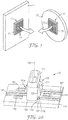
- mating mechanical fasteners such as hook and loop products and 3MTM DUAL LOCK TM reclosable fasteners provide an alternative to conventional attachment means such as adhesives and welding.
- An exemplary mating mechanical fastener is illustrated in FIG. 1 .
- First half 11 of the mating mechanical fastener includes first base 15, which is adhered to first part 21, and first stems 13 (e.g., mushroom headed stems).
- Second half 12 of the mating fastener includes second base 16 which is adhered to second part 22, and second stems 17.
- first stems 13 and second stems 17 are selected to achieve the desired interlocking and removal forces when first stems 13 are mated with second stems 17 to mechanically couple first part 21 to second part 22.
- Such mating mechanical fasteners provide an effective means for releasably and repositionably mechanically coupling one part to another.
- the two mating halves of such mating mechanical fasteners are attached to their respective parts prior to connecting the halves to complete the mechanical attachment of one part to another.
- adhesives are used to attach each half of a mating mechanical fastener to its respective part such that they remain affixed to their parts as one part is releasably and repositionably connected top another part via the mating mechanical fastener.
- pop-in mechanical fasteners As an alternative to adhering a portion of a mating mechanical fastener directly to a part using adhesives and the like, pop-in mechanical fasteners have been used to provide an anchoring point to which mating mechanical fasteners can be attached, e.g., adhered.
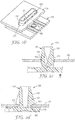
- An exemplary pop-in mechanical fastener according to some embodiments of the present disclosure is shown in FIGS. 2a-2d .
- exemplary pop-in mechanical fastener 100 comprises base 140 and pin 105 connected to the base.
- Pin 105 includes insertion rim 110, and at least one locking tab 115 extending outward relative to insertion axis 101, which is generally perpendicular to base 140, although other orientations are possible.
- Locking tab 115 is pivotally connected to insertion rim 110, and includes wing 120 and terminal stem 130.
- Wing 120 includes insertion surface 121 and locking surface 127.
- the pop-in mechanical fastener includes at least two locking tabs, and in some embodiments, at least three locking tabs.
- at least one locking tab e.g., locking tab 115a
- pop-in mechanical fastener 100 can be connected to part 160 by inserting pin 105 into locking hole 165. After insertion rim 110 has passed through locking hole 165, perimeter 166 of locking hole 165 encounters insertion surface 121.
- an insertion force is applied to continue inserting pin 105 into locking hole 165.
- the insertion force depends on the force required to pivot the one or more locking tab(s) 115 about insertion rim 110, as the tabs(s) are pressed into the open center of pin 105, thereby allowing pin 105 to pass through locking hole 165.
- pop-in mechanical fastener 100 is fully inserted when base 140 contacts part 160.
- the design of pop-in mechanical fastener 100 is selected relative to the dimensions of locking hole 165 and part 160 such that locking tab 115 springs back out of the center of pin 105.
- the perimeter of locking hole 165 will contact locking surface 127 of wing 120, firmly holding pop-in mechanical fastener 100 to part 160.
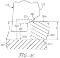
- Locking tab 315 includes wing 320 extending from insertion rim 310 to terminal stem 330, which is adjacent base 340 of a pop-in mechanical fastener.
- Wing 320 includes insertion surface 321, shoulder 322, and locking surface 327.
- Locking surface 327 consists of first angled stop 323, second angled stop 325, and step 324 connecting them.
- Insertion surface 321 forms an angle, A, relative to insertion axis 301, which is perpendicular to base 340.
- the greater the angle A the greater the insertion force required when pressing the pop-in mechanical fastener into place. Also, the greater the angle A, the greater the maximum width, W, of locking tab 315.
- both first angled stop 323 and second angled stop 325 form the same angle, B, relative to wing axes 302a and 302b, which are perpendicular to insertion axis 301.
- the shallower the angle B the greater the extraction force required when removing the pop-in mechanical fastener.
- the width, W, of wing 320 required to provide the same range of height, H1 , for first angled stop 323 and height, H2, for second angled stop 325.
- the width of wing 320 increases, the greater the required angle A for a fixed height fastener, leading to an undesirable increase in insertion force, as described above.
- part 390a has a thickness, Ta, falling between distance 422 and distance 423.
- second surface 397a contacts base 340 i.e., the pop-in mechanical fastener is fully inserted
- first surface 396a has passed beyond shoulder 322 and locking tab 315 springs into place until first surface 396a engages first angled stop 323, holding part 390a in place.
- part 390b has a thickness, Tb, falling between distance 423 and distance 424.
- first surface 396b has passed beyond shoulder 322 and locking tab 315 springs into place. Because thickness Tb of part 390b is less than distance 423, first surface 396b does not engage first angled stop 323; rather, locking tab 315 springs outward until step 324 encounters the perimeter of locking hole 365b.
- Part 390b is held in place near base 340, but some undesirable movement of perpendicular base 340 can occur equal to the difference between thickness Tb of part 390b and distance 423.
- part 390c has a thickness, Tc, falling between distances 424 and 425.
- first surface 396c passes beyond shoulder 322 and locking tab 315 begins springing into place.
- the motion of the tab is stopped when step 324 encounters the perimeter of locking hole 395c.
- the second surface 397c contacts base 340, and first surface 396c passes beyond step 324 allowing locking tab 315 to finish springing into place until top first surface 396c engages second angled stop 325, holding part 390c in place.
- the present inventors have identified a variety of deficiencies with a pop-in mechanical fastener employing a locking tab of the prior art. For example, for certain part thicknesses, significant and undesirable motion perpendicular to the base can occur. In addition, the presence of a step between the two angled stops can result in improper insertion as the tab can stick or hang-up on the step rather than passing on to the second angled stop. This can lead to a loose fit, low extraction forces, and even failure. Finally, the use of two angled stops each having the same angle can limit the range of suitable part thicknesses while maintaining an acceptable level of insertion force.
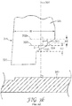
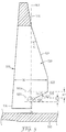
- Locking tab 515 includes wing 520 extending from insertion rim 510 to terminal stem 530, which is adjacent base 540 of a pop-in mechanical fastener.
- Wing 520 includes insertion surface 521, shoulder 522, and locking surface 527.
- Locking surface 527 consists of first angled stop 523 and second angled stop 525.
- Insertion surface 521 formes an angle, C, relative to insertion axis 501.
- First angled stop 523 forms an angle, D, relative to wing axis 502a, which is perpendicular to insertion axis 501.
- second angled stop 525 forms an angle, E, relative to wing axis 502b.
- the shallower the angles D and E the greater the extraction force required when removing the pop-in mechanical fastener.
- angle D decreases, the greater the width, W, of wing 520 required to provide the same range of height, H1 , for first angled stop 523.
- a shallower angle E may be desired to increase the extraction force, as angle E decreases, the greater the width, W, of wing 520 required to provide the same range of height, H2, for second angled stop 525.
- the width of wing 520 increases, the greater the required angle C for a fixed height fastener, leading to an undesirable increase in insertion force, as described above.
- angle E is greater than angle D, providing a steeper slope for second angled stop 525.
- a steeper angle still provides an adequately high removal force.
- a shallower angle D may be required to maintain an acceptable removal force for the thicker parts that would be held in place by first angled stop 523.
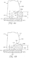
- part 590a has a thickness, Ta, falling between maximum stop height 622 (which in this embodiment corresponds to the point of intersection between the first angled stop and the shoulder) and first intermediate stop height 623, which corresponds to the minimum distance between base 540 and first angled stop 523.
- maximum stop height 622 which in this embodiment corresponds to the point of intersection between the first angled stop and the shoulder
- first intermediate stop height 623 which corresponds to the minimum distance between base 540 and first angled stop 523.
- part 590b has a thickness, Tb, falling between second intermediate stop height 624, corresponding to the maximum distance between base 540 and second angled stop 525, and minimum stop height 625, corresponding to the minimum distance between base 540 and second angled stop 525 (which in this embodiment corresponds to the point where the second angled stop intersects the terminal stem).
- Tb thickness
- second intermediate stop height 624 corresponding to the maximum distance between base 540 and second angled stop 525
- minimum stop height 625 corresponding to the minimum distance between base 540 and second angled stop 525 (which in this embodiment corresponds to the point where the second angled stop intersects the terminal stem).
- first intermediate stop height 623 (which corresponds to the minimum distance between the base and the first angled stop) is equal to second intermediate stop height 624 (which corresponds to the maximum distance between the base and the first angled stop).
- second intermediate stop height 624 (which corresponds to the maximum distance between the base and the first angled stop).
- locking tab 515 finishes springing into place until first surface 596b engages second angled stop 525, holding part 590b in place.
- the range of part thicknesses suitable for use with a particular pop-in mechanical fastener depends in part on the design of the locking surface. Specifically, the range of part thicknesses is generally equal to the difference between maximum stop height 622 and minimum stop height 625. Generally, the actual maximum part thickness and the minimum part thickness will be affected by the gap between the terminal stem and the base as well as the height of the terminal stem; however, the range of part heights (i.e., the difference between the maximum stop height and the minimum stop height) will not be affected by these parameters.
- pop-in mechanical fasteners can be easily modified to accommodate different minimum and maximum part heights by adjusting the gap between the terminal stem and the base and/or the length of the terminal stem.
- a pop-in mechanical fastener could be designed to have a locking surface providing a difference between the maximum stop height and the minimum stop height of 1.2 mm.
- the sum of the gap and the length of the tenninal stem to be 1 mm
- such a fastener would accommodate parts ranging in thickness from about 1 mm to about 2.2 mm.
- the same fastener design would accommodate parts ranging in thickness from about 3 mm to about 4.2 mm.
- spring tabs 150 may expand the useful range of part thicknesses for a particular locking surface design.
- spring tabs 150 are pivotally connected to the top surface of base 140. Prior to insertion, the spring tabs are angled up away from the surface of the base; however, there is a space below the spring tabs allowing the spring tabs to be deflected into the base such that they are flush with the top surface of the base.
- the top of part 590b will engage locking surface 527 when the bottom surface of the part pressed against base 540.
- the top of the part would be located somewhere below the locking surface, allowing some undesirable vertical motion.
- thinner parts will rest on the tops of the spring tabs, which are elevated above the top surface of the base. Thus these thinner parts will contact the locking surface and eliminate vertical motion. Because the spring tabs can flex into the base and become flush with the base, the presence of the spring tabs does not alter the upper limit of the part thickness that can be used.
- the resistance to bending of the spring tabs may provide some upward force pressing the part against the locking surface, further minimizing any vertical movement.
- the dual-angle tabs described above are adequate in many situations, it may be desirable to include more than two angled stops, e.g., three or even four or more angled stops.
- the locking surface could include a curved stop having an infinite number of angled stops. Such embodiments are exemplified in FIGS . 7 and 8 , as follows.
- Locking tab 715 includes wing 720 extending from insertion rim 710 to terminal stem 730, which is adjacent base 740 of a pop-in mechanical fastener.
- Wing 720 includes insertion surface 721, shoulder 722, and locking surface 727.
- Locking surface 727 consists of first angled stop 723, second angled stop 725, and third angled stop 726.
- Insertion surface 721 forms an angle, J, relative to insertion axis 701. The greater the angle J, the greater the insertion force required when pressing the pop-in mechanical fastener into place.
- First angled stop 723 forms an angle, K, relative to wing axis 702a, which is perpendicular to insertion axis 701.
- second angled stop 725 forms an angle, L, relative to wing axis 702b
- third angled stop 726 forms an angle, M, relative to wing axis 702c.
- the shallower the angles K, L, and M the greater the extraction force required when removing the pop-in mechanical fastener.
- the width, W, of wing 720 must increase to provide the same range of height for each of the respective angled stops.
- the width of wing 720 increases, the greater the required angle J for a fixed height fastener, leading to an undesirable increase in insertion force, as described above.
- angle L is greater than angle K, providing a steeper slope for second angled stop 725.
- angle M is greater than angle L, providing a steeper slope for third angled stop 726.
- angle L is greater than angle K, and angle M being greater than angle L.
- the present inventors have discovered that for the thinner parts that will engage the steeper angled stop, a steeper angle provides an adequately high removal force.
- shallower angles may be required to maintain an acceptable removal force for the thicker parts that would be held in place by the progressively shallower angled stops.
- a progression of angled stops a greater range of part thickness may be accommodated without requiring an undesirable increase in width, W, of wing 720, and the corresponding undesirable increase in insertion force resulting from an increase in angle J.
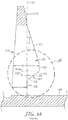
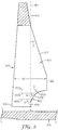
- FIG . 8 shows a locking tab in accordance with the invention.
- the tangent to any point along the curve defines an angled stop; thus, the curved surface could be considered as having an infinite number of angled stops.
- FIG . 8 illustrates a locking surface consisting of a single curve, locking surfaces combining linear and curved stops, as well as compound curved locking surfaces may be used.
- locking tab 815 includes wing 820 extending from insertion rim 810 to terminal stem 830, which is adjacent base 840 of a pop-in mechanical fastener.
- Wing 820 includes insertion surface 821, shoulder 822, and curved locking surface 827.
- Insertion surface 821 forms an angle, P, relative to insertion axis 801. The greater the angle P, the greater the insertion force required when pressing the pop-in mechanical fastener into place.
- Line 803a is tangent to locking surface 827 near shoulder 822, and forms an angle, Q, relative to wing axis 802a, which is perpendicular to insertion axis 801.
- line 803c is tangent to locking surface 827 near terminal stem 830, and forms an angle, S, relative to wing axis 802c.
- An infinite number of tangent lines could be drawn between lines 803a and 803c, each forming an angle relative to a wing axis perpendicular to insertion axis 801.
- line 803b is tangent to locking surface 827 at an arbitrary location between lines 803a and 803c, and forms an angle, R, relative to wing axis 802b.
- locking surface 827 is concave, i.e., the angle of a line tangent to locking surface 827 increases along the path of locking surface 827 from shoulder 822 to terminal stem 830.
- the pop-in mechanical fasteners may be made according to any known means including, e.g., injection molding.
- the injection mold may be produced using standard processes to form the desired part design.
- the pop-in mechanical fasteners may be formed (e.g., injection molded) from any suitable material including, e.g., thermoplastic, elastomers, thermoplastic elastomers, curable resins (e.g., thermosetting, moisture curable, and radiation curable resins), and the like.
- materials e.g., thermoplastic polymers that exhibit good elastic recovery properties and tensile strength may be used.
- polymers that are relatively insensitive to humidity and have suitable tensile properties up to 120 degrees C (° C) (250 degrees F) may be used.
- suitable thermoplastic resins include polypropylene, semicrystalline polymer resins such as polyolefins and polyolefin copolymers (e.g., based upon monomers having between 2 and 8 carbon atoms such as polyethylene, polypropylene, ethylene-propylene copolymers, etc.), polyesters, co-polyesters, nylon, polyamides, co-polyamides, fluorinated homopolymers and copolymers, polyalkylene oxides (e.g., polyethylene oxide and polypropylene oxide), ionomers (e.g., ethylene-methacrylic acid copolymers neutralized with base or salt), cellulose acetate, polyacrylonitrile, polyvinyl chloride, thermoplastic polyurethanes, epoxies (e.g., aromatic e
- the pop-in mechanical fastener may be attached to any part having a suitable opening for insertion of the pin.
- the major surface of the base opposite the pin i.e., the exposed major surface of the base
- one half of a mating mechanical fastener may be attached to the exposed major surface of the base.
- Suitable methods for attaching the mechanical fastener include adhesives (e.g., pressure sensitive adhesives), ultrasonic bonding, insert molding, and extrusion of a molten polymer layer that bonds the fastener to the based.
- adhesives e.g., pressure sensitive adhesives
- ultrasonic bonding e.g., ultrasonic bonding
- insert molding e.g., insert molding
- extrusion of a molten polymer layer that bonds the fastener to the based.
- it is preferred that the bond of the mating mechanical fastener to the base is stronger than the pop-in mechanical fastener disengagement strength (i.e., the force required to remove (or destroy during attempted removal of) the pop-in mechanical fastener.
- first pop-in mechanical fastener useful over the range of thicknesses typical of the first part.
- a second pop-in mechanical fastener could them be designed to for use over the typical range of thicknesses for the second part.
- the bases of these two pop-in mechanical fasteners could be bonded to each other, either directly or indirectly (e.g., through the use of adhesives).
- the stem of the first pop-in mechanical fastener would be inserted into the appropriate hole in the first part, leaving the stem of the second pop-in mechanical fastener exposed.
- the mechanical fasteners of the present disclosure can be produced continuously or individually.
- the pop-in mechanical fasteners are aligned and fed into a laminator which laminates a continuous strip of one half of a mating mechanical fastener to the exposed major surface of base.
- the individual pop-in mechanical fasteners can then be separated into individual pop-in mechanical fasteners having one half of a mating mechanical fastener attached to them.
- the dimensions of the various parts of pop-in mechanical fasteners according to the present disclosure will depend on a number of factors including: the range in thickness of the parts the pop-in mechanical fastener can accommodate and the tolerable dimensions for the holes in the part required to permit insertion of the pins.
- the dimensions of the base are not critical, and can be selected based on well-understood criteria such as surface area required for bonding, mechanical strength, and cost.
- the pin dimensions will be selected based on additional criteria, as many of the dimensions are interrelated and selection of one dimension (e.g., the width of the pin) can limit the selection of other dimensions (e.g., the insertion angle).
- Total Pin Height is defined as the distance from the top surface of the base to the top edge of the pin. Generally, it is desirable to minimize this dimension due to both cost and space considerations. For example, the pin will extend through the hole so there must be adequate space behind the panel to accommodate the pin. However, the minimum total pin height should accommodate the total range of panel thickness likely to be encountered. In some embodiments, the total pin height may be at least five times the maximum intended panel thickness, e.g., at least six times, or even seven times the maximum panel thickness. In some embodiments, the total pin height may be no greater than ten times, e.g., no greater than nine times, or even no greater than eight times the maximum intended panel thickness. For example, for the automotive application described above, a total pin height of 8 to 9 mm (e.g., 8.55 mm) may be used with a maximum intended panel thickness of 1.2 mm.
- the walls of the pin enclose the open center of the pin and define the shape of the pin.
- the pin width is measured parallel to the tabs.
- the pin thickness is defined as the thickness of the walls of the pin.
- the walls of the pin have a constant thickness along the height of the pin.
- the pin wall is tapered near the insertion edge. Generally, a tight fit of the pin in the hole of the part is desired to prevent or minimize movement. However, it may be desirable to taper the insertion edge so that it is easier to initiate insertion of the pin in to the hole.
- the width of the tabs depends on at least one of the following factors, the pin height, the insertion angle, the heights of the angled stops, and the relative angles of the angled stops.
- the maximum pin width is affected by the available open space within the pin.
- the pin width and the pin thickness control the width of the opening within the pin, which limits the size of the tabs. Specifically. as the pin is inserted into a hole in a part, the tab(s) are deflected into the open center of the pin. When the tabs encounter the opposite interior surface of the pin, they can no longer flex. Thus, the maximum tab width is affected by the open area within the pin parallel to the deflection of the tabs.
- the insertion angle may be selected based on, e.g., the pin height, the desired width of the tabs, the available space for deflection within the pin, and the desired insertion force. In some embodiments, the insertion angle is no greater than 45 degrees, e.g., no greater than 30 degrees, or even no greater than 25 degrees. In some embodiments, the insertion angle is at least 13 degrees, e.g., at least 18 degrees. In some embodiments, the insertion angle is between 20 and 25 degrees, e.g., 23 degrees.
- the angle of the first angled stop may be selected based on the insertion angle, the desired height of the first angled stop, and the available deflection space within the pin.
- the first angle is at least 1 degree, e.g., at least 5 degrees, or even at least 15 degrees.
- the first angle is no greater than 45 degrees, e.g., no greater than 40 degrees.
- the first angle is between 20 and 30 degrees, e.g., 27 degrees.
- the angle of the second angled stop may be selected based on the insertion angle, the desired height of the second angled stop, and the available deflection space within the pin. The second angle is greater than the first angle, but is less than 90°.
- the second angle is greater than the first angle by at least 5 degrees, e.g., at least 10 degrees, or even by at least 20 degrees. In some embodiments, the second angle is at least 25 degrees, e.g., at least 35 degrees. In some embodiments, the second angle is no greater than 70 degrees, e.g., no greater than 65 degrees. In some embodiments, the second angle is between 27 and 65 degrees, e.g., between 40 and 50 degrees, e.g., 47 degrees.
- the height of the first angled stop is typically selected based on the total pin height, the available deflection space within the pin, the angle of the first angled stop and the angle of the second angled stop, and the desired range of part thicknesses.
- the height of the second angled stop is typically selected based on the total pin height, the available deflection space within the pin, the angle of the first angled stop and the angle of the second angled stop, and the desired range of part thicknesses.
- the height of the first angled stop may be between 0.25 and 0.35 mm, e.g., 0.31 mm.
- the height of the second angled stop may be between 0.75 and 0.9 mm, e.g., between 0.8 and 0.85 mm. e.g., 0.82 mm.
- the total height of the angled stops (i.e., the sum of the heights of the first angled stop and the second angled stop) should be greater than the maximum expected part thickness, and sufficient to accommodate the desired range of part thickness.
- the total height of the angled stops should span 0.50 mm.
- a total height of 1.13 mm has been shown to cover a range of part thickness of 0.65 to 1.30 mm, or a total range of 0.65 mm.
- a pop-in mechanical fastener was designed according to the dimensions set forth in Table 1.
- the fastener included three tabs with substantially identical dimensions. Two tabs were positioned on one side of the pin and the third tab was position on the opposite side of the pin.
- This exemplary pop-in mechanical fastener is depicted in FIG. 2a and the tabs are illustrated in FIG. 5 .
- Table 1 Pop-in mechanical fastener dimensions.
- Polypropylene resin (PROF-FAX 6523 polypropylene resin obtained from Himont U.S.A., Inc., Wilmington, Delaware) was pigmented with 2 parts of black color concentrate (CBK 00010 Black obtained from Clariant Corp., Charlotte, North Carolinal per 100 parts of the polypropylene resin.
- the pigmented resin was injection molded per the desired dimensions.
- grooves 141 in the top surface of base 140 were provided to allow material to flow during the injection molding process used to create the pop-in mechanical fastener. Such grooves may be desirable when forming the locking tabs for pop-in mechanical fasteners designed for very thin part thicknesses (e.g., less than 1 mm). Other formation methods or fastener designs may not require such grooves.
- One half of a mating mechanical fastener (3MTM Dual LockTM) was attached to the exposed base of the pop-in mechanical fastener as follows.
- the exposed surface of the base of the pop-in mechanical fastener was primed with 4298UV Promoter (available from 3M Company, St. Paul, Minnesota) and a 25.4 mm by 26 mm piece of Clear Dual LockTM SJ3560 (available from 3M Company) was bonded to the primed surface of the base. Care was taken to insure adequate/maximum adhesive contact and minimize any air entrapment. The sample was allowed to dwell for about 16 hours at room temperature before testing.
- Each hole had a major axis (i.e., a hole length) of 21.5 mm.
- the minor axis of the holes i.e., the hole width
- thinner panels require narrower width holes to minimize or prevent both vertical and sideways movement.
- Thicker panels require a wider hole for the tabs to open up. For thicker panels, both vertical and sideways movement are eliminated or minimized by the tabs opening up and catching on the panel.
- the minimum panel thickness for this was 0.65 mm for a 5.25 mm hole width. This resulted in minimal vertical and sideways movement.
- the hole width needed to be increased from 5.25 mm to 5.75 mm in order for the tabs to clear the hole and snap open upon insertion.
- the maximum panel thickness was 1.35mm with a 6.25 mm hole width. At this thickness, the panel needed to be moved sideways for the tabs to pop open. Extraction performance was expected to be reduced as only a small amount/area of the tab would catch on the perimeter of the hole.
- Insertion Force Test Method One half a mating mechanical fastener was adhered to the exposed surface of the base of a pop-in mechanical fastener as described in the Example. The second half of the mating mechanical fastener was removably attached to the first half to assist in maintaining the desired orientation of the pop-in mechanical fastener relative to the hole during the insertion force test.
- the pop-in mechanical fastener was inserted using a Chatillon tensile tester (Model UTSM, available from John Chatillon & Sons, New York).
- the pop-in mechanical fastener was inserted at a rate of about 3.8 cm/minute (1.5 inches/minute) and the peak insertion force was measured using a Chatillon Digital Force Gauge (Model Number DFGS100) set in its "peak compression mode”.
- Extraction Force Test Method A hot melt adhesive has applied to a second half of a complimentary mating mechanical fastener (SJ3221 available from 3M). This complimentary half was mechanically engaged with the first half of the mating mechanical fastener bonded to the base of the pop-in mechanical fastener. The adhesive firmly held the parts together such that they would not disengage during the extraction test.
- the pop-in mechanical fastener was then extracted with the pin aligned with the hole in the metal test panel at a rate of about 30 cm/min. (12 inches/minute) using the Chatillon Tensile Tester and the Chatillon Digital Force Gauge set in its "peak tension mode.” The maximum extraction force was measured and the test termination mode was recorded.
- test termination mode was recorded as "Removal.” If the peak extraction force occurred without removing the pop-in mechanical fastener (e.g., an adhesive failed), the termination mode was recorded as "Destruction.” Regardless of the termination mode, all samples exhibited an extraction force of at least 311 N (70 lbf) and most samples were destroyed rather than being removed at extraction forces exceeding 380 N (85 lbf).
Landscapes
- Engineering & Computer Science (AREA)
- General Engineering & Computer Science (AREA)
- Mechanical Engineering (AREA)
- Insertion Pins And Rivets (AREA)
- Snaps, Bayonet Connections, Set Pins, And Snap Rings (AREA)
- Slide Fasteners, Snap Fasteners, And Hook Fasteners (AREA)
Applications Claiming Priority (2)
| Application Number | Priority Date | Filing Date | Title |
|---|---|---|---|
| US11/940,514 US20090126168A1 (en) | 2007-11-15 | 2007-11-15 | Multi-Angle Pop-In Mechanical Fastener |
| EP08849714.4A EP2222967A4 (en) | 2007-11-15 | 2008-11-11 | REVERSIBLE MECHANICAL MULTI-ANGLE FASTENER |
Related Parent Applications (1)
| Application Number | Title | Priority Date | Filing Date |
|---|---|---|---|
| EP08849714.4A Division EP2222967A4 (en) | 2007-11-15 | 2008-11-11 | REVERSIBLE MECHANICAL MULTI-ANGLE FASTENER |
Publications (2)
| Publication Number | Publication Date |
|---|---|
| EP2696083A1 EP2696083A1 (en) | 2014-02-12 |
| EP2696083B1 true EP2696083B1 (en) | 2017-03-01 |
Family
ID=40639408
Family Applications (2)
| Application Number | Title | Priority Date | Filing Date |
|---|---|---|---|
| EP13187861.3A Not-in-force EP2696083B1 (en) | 2007-11-15 | 2008-11-11 | Multi-angle pop-in mechanical fastener |
| EP08849714.4A Withdrawn EP2222967A4 (en) | 2007-11-15 | 2008-11-11 | REVERSIBLE MECHANICAL MULTI-ANGLE FASTENER |
Family Applications After (1)
| Application Number | Title | Priority Date | Filing Date |
|---|---|---|---|
| EP08849714.4A Withdrawn EP2222967A4 (en) | 2007-11-15 | 2008-11-11 | REVERSIBLE MECHANICAL MULTI-ANGLE FASTENER |
Country Status (7)
| Country | Link |
|---|---|
| US (2) | US20090126168A1 (enExample) |
| EP (2) | EP2696083B1 (enExample) |
| JP (1) | JP5677848B2 (enExample) |
| KR (1) | KR20100092481A (enExample) |
| CN (2) | CN101910648A (enExample) |
| BR (1) | BRPI0819000A2 (enExample) |
| WO (1) | WO2009064711A2 (enExample) |
Families Citing this family (39)
| Publication number | Priority date | Publication date | Assignee | Title |
|---|---|---|---|---|
| US8156991B2 (en) * | 2009-03-19 | 2012-04-17 | Nien Made Enterprises Co., Ltd. | Cord lock of window coverings |
| US9812684B2 (en) | 2010-11-09 | 2017-11-07 | GM Global Technology Operations LLC | Using elastic averaging for alignment of battery stack, fuel cell stack, or other vehicle assembly |
| WO2013088447A1 (en) * | 2011-12-15 | 2013-06-20 | Faurecia Interior Systems India Pvt. Ltd. | Assembly comprising two elements attached by invisible attachment organs |
| US9618026B2 (en) | 2012-08-06 | 2017-04-11 | GM Global Technology Operations LLC | Semi-circular alignment features of an elastic averaging alignment system |
| US20140041185A1 (en) * | 2012-08-13 | 2014-02-13 | GM Global Technology Operations LLC | Elastic tube alignment and attachment system and method for precisely locating and attaching components |
| US9463538B2 (en) | 2012-08-13 | 2016-10-11 | GM Global Technology Operations LLC | Alignment system and method thereof |
| DE202012103421U1 (de) * | 2012-09-07 | 2013-01-14 | Friedrich Münch GmbH & Co. KG | Schließband zur Befestigung an einer aus einem Metallringgeflecht gebildeten Schlaufe einer Schutzbekleidung und solch eine Schutzbekleidung |
| US9556890B2 (en) | 2013-01-31 | 2017-01-31 | GM Global Technology Operations LLC | Elastic alignment assembly for aligning mated components and method of reducing positional variation |
| US9278642B2 (en) | 2013-04-04 | 2016-03-08 | GM Global Technology Operations LLC | Elastically deformable flange locator arrangement and method of reducing positional variation |
| US9388838B2 (en) | 2013-04-04 | 2016-07-12 | GM Global Technology Operations LLC | Elastic retaining assembly for matable components and method of assembling |
| US9447840B2 (en) | 2013-06-11 | 2016-09-20 | GM Global Technology Operations LLC | Elastically deformable energy management assembly and method of managing energy absorption |
| US9488205B2 (en) | 2013-07-12 | 2016-11-08 | GM Global Technology Operations LLC | Alignment arrangement for mated components and method |
| US9303667B2 (en) | 2013-07-18 | 2016-04-05 | Gm Global Technology Operations, Llc | Lobular elastic tube alignment system for providing precise four-way alignment of components |
| US9863454B2 (en) | 2013-08-07 | 2018-01-09 | GM Global Technology Operations LLC | Alignment system for providing precise alignment and retention of components of a sealable compartment |
| US9458876B2 (en) | 2013-08-28 | 2016-10-04 | GM Global Technology Operations LLC | Elastically deformable alignment fastener and system |
| US9463831B2 (en) | 2013-09-09 | 2016-10-11 | GM Global Technology Operations LLC | Elastic tube alignment and fastening system for providing precise alignment and fastening of components |
| US9457845B2 (en) | 2013-10-02 | 2016-10-04 | GM Global Technology Operations LLC | Lobular elastic tube alignment and retention system for providing precise alignment of components |
| US9511802B2 (en) | 2013-10-03 | 2016-12-06 | GM Global Technology Operations LLC | Elastically averaged alignment systems and methods |
| US9669774B2 (en) | 2013-10-11 | 2017-06-06 | GM Global Technology Operations LLC | Reconfigurable vehicle interior assembly |
| US9481317B2 (en) | 2013-11-15 | 2016-11-01 | GM Global Technology Operations LLC | Elastically deformable clip and method |
| US9428123B2 (en) | 2013-12-12 | 2016-08-30 | GM Global Technology Operations LLC | Alignment and retention system for a flexible assembly |
| US9447806B2 (en) | 2013-12-12 | 2016-09-20 | GM Global Technology Operations LLC | Self-retaining alignment system for providing precise alignment and retention of components |
| US9599279B2 (en) | 2013-12-19 | 2017-03-21 | GM Global Technology Operations LLC | Elastically deformable module installation assembly |
| US9446722B2 (en) | 2013-12-19 | 2016-09-20 | GM Global Technology Operations LLC | Elastic averaging alignment member |
| US9541113B2 (en) | 2014-01-09 | 2017-01-10 | GM Global Technology Operations LLC | Elastically averaged alignment systems and methods |
| CN103818598A (zh) * | 2014-03-14 | 2014-05-28 | 胡和萍 | 一种不干胶贴标机的分料固定器 |
| US9428046B2 (en) | 2014-04-02 | 2016-08-30 | GM Global Technology Operations LLC | Alignment and retention system for laterally slideably engageable mating components |
| US9657807B2 (en) | 2014-04-23 | 2017-05-23 | GM Global Technology Operations LLC | System for elastically averaging assembly of components |
| US9429176B2 (en) | 2014-06-30 | 2016-08-30 | GM Global Technology Operations LLC | Elastically averaged alignment systems and methods |
| JP6437228B2 (ja) * | 2014-07-23 | 2018-12-12 | 岐阜プラスチック工業株式会社 | 留め具 |
| US9758110B2 (en) | 2015-01-12 | 2017-09-12 | GM Global Technology Operations LLC | Coupling system |
| US10107319B2 (en) | 2015-03-02 | 2018-10-23 | GM Global Technology Operations LLC | Elastically averaged alignment systems and methods |
| US10316695B2 (en) | 2015-12-10 | 2019-06-11 | General Electric Company | Metallic attachment system integrated into a composite structure |
| JP6715037B2 (ja) * | 2016-03-04 | 2020-07-01 | 株式会社 Mtg | 美容器 |
| US10202085B2 (en) * | 2016-08-25 | 2019-02-12 | Aplix | Fastener |
| TWM552955U (zh) * | 2017-08-04 | 2017-12-11 | 伍鐌科技股份有限公司 | 扣接裝置 |
| EP3521641B1 (en) * | 2018-02-05 | 2020-08-26 | Ford Global Technologies, LLC | Vehicle headliner attachment |
| CN110439900B (zh) * | 2018-12-29 | 2024-08-30 | 盐城世明电子器件有限公司 | 卡扣安装机构和卡扣安装组件 |
| WO2025030257A1 (zh) * | 2023-08-04 | 2025-02-13 | 3M创新有限公司 | 一种蘑菇搭扣联接结构 |
Citations (3)
| Publication number | Priority date | Publication date | Assignee | Title |
|---|---|---|---|---|
| DE2153062A1 (de) * | 1970-10-26 | 1972-04-27 | Itw Ltd | Kunststoffbefestigungselement |
| GB2026083A (en) * | 1978-06-19 | 1980-01-30 | United Carr Ltd | Fastener |
| US20070023586A1 (en) * | 2005-07-28 | 2007-02-01 | Hellermann Tyton Corporation | Harness clamp tie |
Family Cites Families (33)
| Publication number | Priority date | Publication date | Assignee | Title |
|---|---|---|---|---|
| GB1341695A (en) * | 1970-01-30 | 1973-12-25 | British Leyland Truck & Bus | Clips |
| DE2226315A1 (de) * | 1972-05-30 | 1973-07-19 | Bourns Inc | Montagevorrichtung fuer instrumente |
| US3871430A (en) * | 1973-10-26 | 1975-03-18 | Usm Corp | Retainer clip |
| DE2718170C3 (de) * | 1977-04-23 | 1979-10-25 | Ford-Werke Ag, 5000 Koeln | Befestigungsclip für verkleidete Abdeckplatten, insbesondere für Kraftfahrzeuge |
| JPS599307A (ja) * | 1982-07-05 | 1984-01-18 | 株式会社ニフコ | 脱着フアスナ |
| US4781488A (en) * | 1982-07-14 | 1988-11-01 | Kitagawa Industries Co., Ltd. | Securing unit |
| JPS61117908U (enExample) * | 1985-01-09 | 1986-07-25 | ||
| US4739543A (en) * | 1987-06-08 | 1988-04-26 | Ford Motor Company | Push pin retainer |
| JPH0534329Y2 (enExample) * | 1988-01-26 | 1993-08-31 | ||
| JPH0614085Y2 (ja) * | 1988-12-03 | 1994-04-13 | 株式会社ニフコ | パネル状部品の固定用クリップ |
| JP2979079B2 (ja) * | 1989-12-07 | 1999-11-15 | 日産自動車株式会社 | 自動車用内装材の取付構造 |
| FR2675545B1 (fr) * | 1992-01-20 | 1993-11-05 | Nicollet Oblique | Procede pour la fixation de boutons-pression du type male. |
| JPH07279918A (ja) * | 1994-04-05 | 1995-10-27 | Ykk Kk | パネル類の連結構造 |
| ES2225325T3 (es) * | 1995-09-19 | 2005-03-16 | Daiwa Kasei Kogyo Kabushiki Kaisha | Pata de retencion flexible para medios de sujecion. |
| KR200153215Y1 (ko) * | 1996-08-06 | 1999-08-02 | 노정웅 | 크립 |
| US6353981B1 (en) * | 1999-02-25 | 2002-03-12 | Termax Corporation | Multi-engagement spring fastener |
| DE19963721B4 (de) * | 1999-12-29 | 2006-05-11 | A. Raymond & Cie | Kunststoffklammer zur lösbaren Verbindung einer Verkleidungsplatte mit einem Trägerteil |
| JP4299471B2 (ja) * | 2001-03-19 | 2009-07-22 | 株式会社パイオラックス | 樹脂クリップ |
| US6857809B2 (en) * | 2001-03-30 | 2005-02-22 | Robert Granata | Articulating fastener assembly |
| US8627552B2 (en) * | 2001-06-25 | 2014-01-14 | Termax Corporation | Multicontact adaptive fastener clip |
| JP3949401B2 (ja) * | 2001-07-05 | 2007-07-25 | 矢崎総業株式会社 | ワイヤハーネス用クランプ |
| JP4155731B2 (ja) * | 2001-10-16 | 2008-09-24 | 矢崎総業株式会社 | ワイヤハーネス用固定具 |
| US6715185B2 (en) * | 2002-07-25 | 2004-04-06 | Illinois Tool Works Inc. | Self aligning panel fastener |
| US6952863B2 (en) * | 2002-09-13 | 2005-10-11 | Southco, Inc. | Tether clip system |
| DE10245276A1 (de) * | 2002-09-27 | 2004-04-01 | A. Raymond & Cie | Befestigungselement |
| US6976292B2 (en) * | 2003-08-28 | 2005-12-20 | Newfrey Llc | Resilient clip fastener |
| US20050217087A1 (en) * | 2004-04-05 | 2005-10-06 | Gallant Christopher M | Self-engaging, double-sided fastener products |
| JP4683858B2 (ja) * | 2004-05-14 | 2011-05-18 | スリーエム イノベイティブ プロパティズ カンパニー | 物品支持具 |
| FR2876166A1 (fr) * | 2005-02-11 | 2006-04-07 | Faurecia Interieur Ind Snc | Agrafe de fixation amelioree et piece de garniture interieure de vehicule automobile equipee d'une telle agrafe |
| US7306419B2 (en) * | 2005-03-21 | 2007-12-11 | Illinois Tool Works Inc | Fastener |
| JP2007174887A (ja) * | 2005-11-24 | 2007-07-05 | Daiwa Kasei Ind Co Ltd | 留め具 |
| US20080066266A1 (en) * | 2006-09-14 | 2008-03-20 | Derek Scroggie | Fastener assembly |
| DE102012010893A1 (de) * | 2012-06-01 | 2013-12-05 | Gottlieb Binder Gmbh & Co. Kg | Befestigungssystem |
-
2007
- 2007-11-15 US US11/940,514 patent/US20090126168A1/en not_active Abandoned
-
2008
- 2008-11-11 EP EP13187861.3A patent/EP2696083B1/en not_active Not-in-force
- 2008-11-11 KR KR1020107012750A patent/KR20100092481A/ko not_active Ceased
- 2008-11-11 CN CN2008801243408A patent/CN101910648A/zh active Pending
- 2008-11-11 WO PCT/US2008/083098 patent/WO2009064711A2/en not_active Ceased
- 2008-11-11 BR BRPI0819000 patent/BRPI0819000A2/pt not_active IP Right Cessation
- 2008-11-11 EP EP08849714.4A patent/EP2222967A4/en not_active Withdrawn
- 2008-11-11 JP JP2010534123A patent/JP5677848B2/ja not_active Expired - Fee Related
- 2008-11-11 CN CN2013100586371A patent/CN103174719A/zh active Pending
-
2013
- 2013-09-16 US US14/027,565 patent/US20140013550A1/en not_active Abandoned
Patent Citations (3)
| Publication number | Priority date | Publication date | Assignee | Title |
|---|---|---|---|---|
| DE2153062A1 (de) * | 1970-10-26 | 1972-04-27 | Itw Ltd | Kunststoffbefestigungselement |
| GB2026083A (en) * | 1978-06-19 | 1980-01-30 | United Carr Ltd | Fastener |
| US20070023586A1 (en) * | 2005-07-28 | 2007-02-01 | Hellermann Tyton Corporation | Harness clamp tie |
Also Published As
| Publication number | Publication date |
|---|---|
| EP2696083A1 (en) | 2014-02-12 |
| EP2222967A4 (en) | 2013-04-17 |
| BRPI0819000A2 (pt) | 2015-05-05 |
| CN101910648A (zh) | 2010-12-08 |
| WO2009064711A3 (en) | 2010-07-01 |
| US20090126168A1 (en) | 2009-05-21 |
| US20140013550A1 (en) | 2014-01-16 |
| KR20100092481A (ko) | 2010-08-20 |
| JP2011503489A (ja) | 2011-01-27 |
| CN103174719A (zh) | 2013-06-26 |
| JP5677848B2 (ja) | 2015-02-25 |
| WO2009064711A2 (en) | 2009-05-22 |
| EP2222967A2 (en) | 2010-09-01 |
Similar Documents
| Publication | Publication Date | Title |
|---|---|---|
| EP2696083B1 (en) | Multi-angle pop-in mechanical fastener | |
| CN100509487C (zh) | 模制件连接结构、模制件连接夹及模制件 | |
| KR200181170Y1 (ko) | 위치 설정 구조를 갖는 맞물림식 파스너 | |
| US6382297B1 (en) | Engaging device | |
| US20040016088A1 (en) | Self aligning panel fastener | |
| US20040137192A1 (en) | Injection molded fastening article for use as a mold insert | |
| BR102014028462A2 (pt) | grampo elasticamente deformável, e, método para unir componentes | |
| KR200181169Y1 (ko) | 상호 결합식 파스너 부재 | |
| KR102597419B1 (ko) | 파스너 | |
| KR20110013508A (ko) | 용품을 표면에 부착시키는 방법 및 조립체 | |
| WO2015052349A1 (en) | Fastener | |
| CN101646365A (zh) | 拉链用自动锁扣塑料滑件 | |
| AU2011373631B2 (en) | Snap feature providing component attachment | |
| US11992098B2 (en) | Hook-and-loop fastener-equipped resin molded body, method for manufacturing same, and method for fixing automobile ceiling material to vehicle body | |
| US12291085B2 (en) | Vehicle window assembly and transport protection strip for use with a vehicle window assembly | |
| US20040251714A1 (en) | System for attaching colored insert to vehicle frame assembly | |
| EP0826532A2 (en) | Mounting structure and mounting method for mounting window panel on window frame of vehicle body | |
| CA2343766A1 (en) | Intermeshable articles | |
| JP6870919B2 (ja) | 雄型面ファスナー及びそれを用いた天井構造体 | |
| CN219293777U (zh) | 适用于轴头类零件的工装夹 | |
| GB2466624A (en) | Locking pin for a slide fastener | |
| GB2494990A (en) | Slide fastener including locking pin | |
| WO2017160638A1 (en) | Surface fastener member and method for manufacturing same | |
| CA1107095A (en) | Blind fastener | |
| KR101638172B1 (ko) | 스냅 파스너용 소켓부재 |
Legal Events
| Date | Code | Title | Description |
|---|---|---|---|
| AC | Divisional application: reference to earlier application |
Ref document number: 2222967 Country of ref document: EP Kind code of ref document: P |
|
| AK | Designated contracting states |
Kind code of ref document: A1 Designated state(s): AT BE BG CH CY CZ DE DK EE ES FI FR GB GR HR HU IE IS IT LI LT LU LV MC MT NL NO PL PT RO SE SI SK TR |
|
| PUAI | Public reference made under article 153(3) epc to a published international application that has entered the european phase |
Free format text: ORIGINAL CODE: 0009012 |
|
| 17P | Request for examination filed |
Effective date: 20141027 |
|
| RBV | Designated contracting states (corrected) |
Designated state(s): AT BE BG CH CY CZ DE DK EE ES FI FR GB GR HR HU IE IS IT LI LT LU LV MC MT NL NO PL PT RO SE SI SK TR |
|
| 17Q | First examination report despatched |
Effective date: 20150720 |
|
| GRAP | Despatch of communication of intention to grant a patent |
Free format text: ORIGINAL CODE: EPIDOSNIGR1 |
|
| INTG | Intention to grant announced |
Effective date: 20160915 |
|
| STAA | Information on the status of an ep patent application or granted ep patent |
Free format text: STATUS: GRANT OF PATENT IS INTENDED |
|
| GRAS | Grant fee paid |
Free format text: ORIGINAL CODE: EPIDOSNIGR3 |
|
| GRAA | (expected) grant |
Free format text: ORIGINAL CODE: 0009210 |
|
| STAA | Information on the status of an ep patent application or granted ep patent |
Free format text: STATUS: THE PATENT HAS BEEN GRANTED |
|
| AC | Divisional application: reference to earlier application |
Ref document number: 2222967 Country of ref document: EP Kind code of ref document: P |
|
| AK | Designated contracting states |
Kind code of ref document: B1 Designated state(s): AT BE BG CH CY CZ DE DK EE ES FI FR GB GR HR HU IE IS IT LI LT LU LV MC MT NL NO PL PT RO SE SI SK TR |
|
| REG | Reference to a national code |
Ref country code: GB Ref legal event code: FG4D |
|
| REG | Reference to a national code |
Ref country code: CH Ref legal event code: EP Ref country code: AT Ref legal event code: REF Ref document number: 871730 Country of ref document: AT Kind code of ref document: T Effective date: 20170315 |
|
| REG | Reference to a national code |
Ref country code: IE Ref legal event code: FG4D |
|
| REG | Reference to a national code |
Ref country code: DE Ref legal event code: R096 Ref document number: 602008049030 Country of ref document: DE |
|
| REG | Reference to a national code |
Ref country code: NL Ref legal event code: MP Effective date: 20170301 |
|
| REG | Reference to a national code |
Ref country code: LT Ref legal event code: MG4D |
|
| REG | Reference to a national code |
Ref country code: AT Ref legal event code: MK05 Ref document number: 871730 Country of ref document: AT Kind code of ref document: T Effective date: 20170301 |
|
| PG25 | Lapsed in a contracting state [announced via postgrant information from national office to epo] |
Ref country code: NO Free format text: LAPSE BECAUSE OF FAILURE TO SUBMIT A TRANSLATION OF THE DESCRIPTION OR TO PAY THE FEE WITHIN THE PRESCRIBED TIME-LIMIT Effective date: 20170601 Ref country code: LT Free format text: LAPSE BECAUSE OF FAILURE TO SUBMIT A TRANSLATION OF THE DESCRIPTION OR TO PAY THE FEE WITHIN THE PRESCRIBED TIME-LIMIT Effective date: 20170301 Ref country code: FI Free format text: LAPSE BECAUSE OF FAILURE TO SUBMIT A TRANSLATION OF THE DESCRIPTION OR TO PAY THE FEE WITHIN THE PRESCRIBED TIME-LIMIT Effective date: 20170301 Ref country code: HR Free format text: LAPSE BECAUSE OF FAILURE TO SUBMIT A TRANSLATION OF THE DESCRIPTION OR TO PAY THE FEE WITHIN THE PRESCRIBED TIME-LIMIT Effective date: 20170301 Ref country code: GR Free format text: LAPSE BECAUSE OF FAILURE TO SUBMIT A TRANSLATION OF THE DESCRIPTION OR TO PAY THE FEE WITHIN THE PRESCRIBED TIME-LIMIT Effective date: 20170602 |
|
| PG25 | Lapsed in a contracting state [announced via postgrant information from national office to epo] |
Ref country code: AT Free format text: LAPSE BECAUSE OF FAILURE TO SUBMIT A TRANSLATION OF THE DESCRIPTION OR TO PAY THE FEE WITHIN THE PRESCRIBED TIME-LIMIT Effective date: 20170301 Ref country code: LV Free format text: LAPSE BECAUSE OF FAILURE TO SUBMIT A TRANSLATION OF THE DESCRIPTION OR TO PAY THE FEE WITHIN THE PRESCRIBED TIME-LIMIT Effective date: 20170301 Ref country code: ES Free format text: LAPSE BECAUSE OF FAILURE TO SUBMIT A TRANSLATION OF THE DESCRIPTION OR TO PAY THE FEE WITHIN THE PRESCRIBED TIME-LIMIT Effective date: 20170301 Ref country code: BG Free format text: LAPSE BECAUSE OF FAILURE TO SUBMIT A TRANSLATION OF THE DESCRIPTION OR TO PAY THE FEE WITHIN THE PRESCRIBED TIME-LIMIT Effective date: 20170601 Ref country code: SE Free format text: LAPSE BECAUSE OF FAILURE TO SUBMIT A TRANSLATION OF THE DESCRIPTION OR TO PAY THE FEE WITHIN THE PRESCRIBED TIME-LIMIT Effective date: 20170301 |
|
| PG25 | Lapsed in a contracting state [announced via postgrant information from national office to epo] |
Ref country code: NL Free format text: LAPSE BECAUSE OF FAILURE TO SUBMIT A TRANSLATION OF THE DESCRIPTION OR TO PAY THE FEE WITHIN THE PRESCRIBED TIME-LIMIT Effective date: 20170301 |
|
| PG25 | Lapsed in a contracting state [announced via postgrant information from national office to epo] |
Ref country code: EE Free format text: LAPSE BECAUSE OF FAILURE TO SUBMIT A TRANSLATION OF THE DESCRIPTION OR TO PAY THE FEE WITHIN THE PRESCRIBED TIME-LIMIT Effective date: 20170301 Ref country code: CZ Free format text: LAPSE BECAUSE OF FAILURE TO SUBMIT A TRANSLATION OF THE DESCRIPTION OR TO PAY THE FEE WITHIN THE PRESCRIBED TIME-LIMIT Effective date: 20170301 Ref country code: RO Free format text: LAPSE BECAUSE OF FAILURE TO SUBMIT A TRANSLATION OF THE DESCRIPTION OR TO PAY THE FEE WITHIN THE PRESCRIBED TIME-LIMIT Effective date: 20170301 Ref country code: SK Free format text: LAPSE BECAUSE OF FAILURE TO SUBMIT A TRANSLATION OF THE DESCRIPTION OR TO PAY THE FEE WITHIN THE PRESCRIBED TIME-LIMIT Effective date: 20170301 Ref country code: IT Free format text: LAPSE BECAUSE OF FAILURE TO SUBMIT A TRANSLATION OF THE DESCRIPTION OR TO PAY THE FEE WITHIN THE PRESCRIBED TIME-LIMIT Effective date: 20170301 |
|
| PG25 | Lapsed in a contracting state [announced via postgrant information from national office to epo] |
Ref country code: IS Free format text: LAPSE BECAUSE OF FAILURE TO SUBMIT A TRANSLATION OF THE DESCRIPTION OR TO PAY THE FEE WITHIN THE PRESCRIBED TIME-LIMIT Effective date: 20170701 Ref country code: PT Free format text: LAPSE BECAUSE OF FAILURE TO SUBMIT A TRANSLATION OF THE DESCRIPTION OR TO PAY THE FEE WITHIN THE PRESCRIBED TIME-LIMIT Effective date: 20170703 Ref country code: PL Free format text: LAPSE BECAUSE OF FAILURE TO SUBMIT A TRANSLATION OF THE DESCRIPTION OR TO PAY THE FEE WITHIN THE PRESCRIBED TIME-LIMIT Effective date: 20170301 |
|
| REG | Reference to a national code |
Ref country code: DE Ref legal event code: R097 Ref document number: 602008049030 Country of ref document: DE |
|
| PLBE | No opposition filed within time limit |
Free format text: ORIGINAL CODE: 0009261 |
|
| STAA | Information on the status of an ep patent application or granted ep patent |
Free format text: STATUS: NO OPPOSITION FILED WITHIN TIME LIMIT |
|
| PG25 | Lapsed in a contracting state [announced via postgrant information from national office to epo] |
Ref country code: DK Free format text: LAPSE BECAUSE OF FAILURE TO SUBMIT A TRANSLATION OF THE DESCRIPTION OR TO PAY THE FEE WITHIN THE PRESCRIBED TIME-LIMIT Effective date: 20170301 |
|
| 26N | No opposition filed |
Effective date: 20171204 |
|
| PG25 | Lapsed in a contracting state [announced via postgrant information from national office to epo] |
Ref country code: SI Free format text: LAPSE BECAUSE OF FAILURE TO SUBMIT A TRANSLATION OF THE DESCRIPTION OR TO PAY THE FEE WITHIN THE PRESCRIBED TIME-LIMIT Effective date: 20170301 |
|
| PG25 | Lapsed in a contracting state [announced via postgrant information from national office to epo] |
Ref country code: MC Free format text: LAPSE BECAUSE OF FAILURE TO SUBMIT A TRANSLATION OF THE DESCRIPTION OR TO PAY THE FEE WITHIN THE PRESCRIBED TIME-LIMIT Effective date: 20170301 |
|
| GBPC | Gb: european patent ceased through non-payment of renewal fee |
Effective date: 20171111 |
|
| PG25 | Lapsed in a contracting state [announced via postgrant information from national office to epo] |
Ref country code: CH Free format text: LAPSE BECAUSE OF NON-PAYMENT OF DUE FEES Effective date: 20171130 Ref country code: LI Free format text: LAPSE BECAUSE OF NON-PAYMENT OF DUE FEES Effective date: 20171130 |
|
| PG25 | Lapsed in a contracting state [announced via postgrant information from national office to epo] |
Ref country code: LU Free format text: LAPSE BECAUSE OF NON-PAYMENT OF DUE FEES Effective date: 20171111 |
|
| REG | Reference to a national code |
Ref country code: FR Ref legal event code: ST Effective date: 20180731 Ref country code: BE Ref legal event code: MM Effective date: 20171130 |
|
| REG | Reference to a national code |
Ref country code: IE Ref legal event code: MM4A |
|
| PG25 | Lapsed in a contracting state [announced via postgrant information from national office to epo] |
Ref country code: MT Free format text: LAPSE BECAUSE OF NON-PAYMENT OF DUE FEES Effective date: 20171111 |
|
| PG25 | Lapsed in a contracting state [announced via postgrant information from national office to epo] |
Ref country code: IE Free format text: LAPSE BECAUSE OF NON-PAYMENT OF DUE FEES Effective date: 20171111 Ref country code: FR Free format text: LAPSE BECAUSE OF NON-PAYMENT OF DUE FEES Effective date: 20171130 |
|
| PG25 | Lapsed in a contracting state [announced via postgrant information from national office to epo] |
Ref country code: GB Free format text: LAPSE BECAUSE OF NON-PAYMENT OF DUE FEES Effective date: 20171111 Ref country code: BE Free format text: LAPSE BECAUSE OF NON-PAYMENT OF DUE FEES Effective date: 20171130 |
|
| PGFP | Annual fee paid to national office [announced via postgrant information from national office to epo] |
Ref country code: DE Payment date: 20181030 Year of fee payment: 11 |
|
| PGFP | Annual fee paid to national office [announced via postgrant information from national office to epo] |
Ref country code: TR Payment date: 20181031 Year of fee payment: 11 |
|
| PG25 | Lapsed in a contracting state [announced via postgrant information from national office to epo] |
Ref country code: HU Free format text: LAPSE BECAUSE OF FAILURE TO SUBMIT A TRANSLATION OF THE DESCRIPTION OR TO PAY THE FEE WITHIN THE PRESCRIBED TIME-LIMIT; INVALID AB INITIO Effective date: 20081111 |
|
| PG25 | Lapsed in a contracting state [announced via postgrant information from national office to epo] |
Ref country code: CY Free format text: LAPSE BECAUSE OF NON-PAYMENT OF DUE FEES Effective date: 20170301 |
|
| REG | Reference to a national code |
Ref country code: DE Ref legal event code: R119 Ref document number: 602008049030 Country of ref document: DE |
|
| PG25 | Lapsed in a contracting state [announced via postgrant information from national office to epo] |
Ref country code: DE Free format text: LAPSE BECAUSE OF NON-PAYMENT OF DUE FEES Effective date: 20200603 |
|
| PG25 | Lapsed in a contracting state [announced via postgrant information from national office to epo] |
Ref country code: TR Free format text: LAPSE BECAUSE OF NON-PAYMENT OF DUE FEES Effective date: 20191111 |