EP2692488B1 - Control device and control method for robot and the robot - Google Patents
Control device and control method for robot and the robot Download PDFInfo
- Publication number
- EP2692488B1 EP2692488B1 EP13178508.1A EP13178508A EP2692488B1 EP 2692488 B1 EP2692488 B1 EP 2692488B1 EP 13178508 A EP13178508 A EP 13178508A EP 2692488 B1 EP2692488 B1 EP 2692488B1
- Authority
- EP
- European Patent Office
- Prior art keywords
- speed
- arm
- robot
- driving
- driving units
- Prior art date
- Legal status (The legal status is an assumption and is not a legal conclusion. Google has not performed a legal analysis and makes no representation as to the accuracy of the status listed.)
- Active
Links
- 238000000034 method Methods 0.000 title claims description 44
- 238000013016 damping Methods 0.000 claims description 98
- 239000011159 matrix material Substances 0.000 claims description 44
- 230000001133 acceleration Effects 0.000 claims description 12
- 230000001629 suppression Effects 0.000 description 18
- 238000010586 diagram Methods 0.000 description 10
- 238000011156 evaluation Methods 0.000 description 7
- 230000008878 coupling Effects 0.000 description 6
- 238000010168 coupling process Methods 0.000 description 6
- 238000005859 coupling reaction Methods 0.000 description 6
- 238000010422 painting Methods 0.000 description 4
- 230000008859 change Effects 0.000 description 3
- 230000009467 reduction Effects 0.000 description 3
- 239000007921 spray Substances 0.000 description 3
- 238000003466 welding Methods 0.000 description 3
- 230000006866 deterioration Effects 0.000 description 2
- 230000006872 improvement Effects 0.000 description 2
- 230000008901 benefit Effects 0.000 description 1
- 238000001514 detection method Methods 0.000 description 1
- 230000000694 effects Effects 0.000 description 1
- 239000003973 paint Substances 0.000 description 1
- 230000008569 process Effects 0.000 description 1
- 238000005303 weighing Methods 0.000 description 1
Images


Classifications
-
- B—PERFORMING OPERATIONS; TRANSPORTING
- B25—HAND TOOLS; PORTABLE POWER-DRIVEN TOOLS; MANIPULATORS
- B25J—MANIPULATORS; CHAMBERS PROVIDED WITH MANIPULATION DEVICES
- B25J9/00—Programme-controlled manipulators
- B25J9/10—Programme-controlled manipulators characterised by positioning means for manipulator elements
-
- B—PERFORMING OPERATIONS; TRANSPORTING
- B25—HAND TOOLS; PORTABLE POWER-DRIVEN TOOLS; MANIPULATORS
- B25J—MANIPULATORS; CHAMBERS PROVIDED WITH MANIPULATION DEVICES
- B25J9/00—Programme-controlled manipulators
- B25J9/16—Programme controls
- B25J9/1628—Programme controls characterised by the control loop
- B25J9/1641—Programme controls characterised by the control loop compensation for backlash, friction, compliance, elasticity in the joints
-
- B—PERFORMING OPERATIONS; TRANSPORTING
- B25—HAND TOOLS; PORTABLE POWER-DRIVEN TOOLS; MANIPULATORS
- B25J—MANIPULATORS; CHAMBERS PROVIDED WITH MANIPULATION DEVICES
- B25J13/00—Controls for manipulators
-
- B—PERFORMING OPERATIONS; TRANSPORTING
- B25—HAND TOOLS; PORTABLE POWER-DRIVEN TOOLS; MANIPULATORS
- B25J—MANIPULATORS; CHAMBERS PROVIDED WITH MANIPULATION DEVICES
- B25J9/00—Programme-controlled manipulators
- B25J9/06—Programme-controlled manipulators characterised by multi-articulated arms
-
- B—PERFORMING OPERATIONS; TRANSPORTING
- B25—HAND TOOLS; PORTABLE POWER-DRIVEN TOOLS; MANIPULATORS
- B25J—MANIPULATORS; CHAMBERS PROVIDED WITH MANIPULATION DEVICES
- B25J9/00—Programme-controlled manipulators
- B25J9/16—Programme controls
- B25J9/1694—Programme controls characterised by use of sensors other than normal servo-feedback from position, speed or acceleration sensors, perception control, multi-sensor controlled systems, sensor fusion
-
- G—PHYSICS
- G05—CONTROLLING; REGULATING
- G05B—CONTROL OR REGULATING SYSTEMS IN GENERAL; FUNCTIONAL ELEMENTS OF SUCH SYSTEMS; MONITORING OR TESTING ARRANGEMENTS FOR SUCH SYSTEMS OR ELEMENTS
- G05B19/00—Programme-control systems
- G05B19/02—Programme-control systems electric
- G05B19/18—Numerical control [NC], i.e. automatically operating machines, in particular machine tools, e.g. in a manufacturing environment, so as to execute positioning, movement or co-ordinated operations by means of programme data in numerical form
- G05B19/404—Numerical control [NC], i.e. automatically operating machines, in particular machine tools, e.g. in a manufacturing environment, so as to execute positioning, movement or co-ordinated operations by means of programme data in numerical form characterised by control arrangements for compensation, e.g. for backlash, overshoot, tool offset, tool wear, temperature, machine construction errors, load, inertia
-
- G—PHYSICS
- G05—CONTROLLING; REGULATING
- G05B—CONTROL OR REGULATING SYSTEMS IN GENERAL; FUNCTIONAL ELEMENTS OF SUCH SYSTEMS; MONITORING OR TESTING ARRANGEMENTS FOR SUCH SYSTEMS OR ELEMENTS
- G05B2219/00—Program-control systems
- G05B2219/30—Nc systems
- G05B2219/39—Robotics, robotics to robotics hand
- G05B2219/39195—Control, avoid oscillation, vibration due to low rigidity
-
- G—PHYSICS
- G05—CONTROLLING; REGULATING
- G05B—CONTROL OR REGULATING SYSTEMS IN GENERAL; FUNCTIONAL ELEMENTS OF SUCH SYSTEMS; MONITORING OR TESTING ARRANGEMENTS FOR SUCH SYSTEMS OR ELEMENTS
- G05B2219/00—Program-control systems
- G05B2219/30—Nc systems
- G05B2219/40—Robotics, robotics mapping to robotics vision
- G05B2219/40549—Acceleration of end effector
Definitions
- the present invention relates to a control device and a control method for a robot and the robot.
- JP-A-2011-136395 proposes a method of suppressing vibration of a robot tip that occurs when the motion of a robot stops.
- Patent Literature 1 proposes a method of providing an acceleration sensor at the tip of the robot and adding, on the basis of a detected torsional angular velocity and a detected torsion angle, a compensation amount for eliminating torsion to a control input of a motor, which drives links, to thereby control vibration. Consequently, improvement of position accuracy during a stop and a reduction in a standby time until suppression of vibration have been attained.
- the control method (the damping method) described in Patent Literature 1 has a problem in that vibration that occurs during the motion of the robot cannot be suppressed. Specifically, since the method is based on the premise that timing for acceleration detection is time when the motion of the robot stops, for example, vibration and motion strain that occur during movement of a robot arm cannot be eliminated. When an operator causes the robot to perform work such as painting or welding while moving the robot, deterioration in accuracy of the work due to vibration cannot be suppressed.
- JP 2011 136395 A is concerned with a robot control device and method.
- US 2012/035763 A1 is concerned with a robotic device and a method for controlling a robotic device.
- An advantage of some aspects of the invention is to solve at least a part of the problems described above, and the invention can be implemented as the following application examples or forms.
- This application example is directed to a control device for a robot as defined in claim 1.
- the third arm speed in the damping position is calculated on the basis of information concerning the first arm speed obtained from the inertia sensor and information concerning the second arm speed obtained from the angle sensor.
- the correction speed for each of driving units that drive the links present between the robot main body and the damping position is calculated on the basis of the calculated third arm speed.
- an actual speed of an arm indicates an ideal arm speed.
- the first arm speed obtained from the inertia sensor is a speed detected according to an actual movement of the damping position where the inertia sensor is attached. That is, the first arm speed is a speed including a speed component such as vibration that occurs accompanying actual motion because of a bend and the like of the arm that does not have ideal rigidity. Therefore, it is possible to extract the speed component due to the bend and the vibration by evaluating a difference between the first arm speed and the second arm speed. It is possible to achieve suppression of the vibration by distributing the extracted speed component to the driving units, which drive the respective links, as the correction speed to generate torque for suppressing the bend and the vibration.
- control device for the robot As explained above, with the control device for the robot according to this application example, it is possible to achieve further increases in accuracy, speed, and the like in the multi-joint robot.
- control device for the robot according to the application example, it is preferable that the control device further includes, in the third calculating unit, a filter for removing a low frequency component equal to or lower than a predetermined frequency included in a waveform of the third arm speed.
- control device since the control device further includes the filter for removing the low frequency component of the third arm speed, it is possible to more appropriately extract a vibration component through the evaluation of the difference between the first arm speed and the second arm speed. Specifically, it is possible to reduce the influence of a wrong correction for suppressing the original motion of the robot arm, an offset error of the inertia sensor, and the like by removing the low frequency component of the third arm speed.
- This application example is directed to a control method for a robot as defined in claim 3.
- the control method for the robot according to this application example includes calculating the third arm speed on the basis of the first arm speed and the second arm speed and subjecting the driving units to the correction control on the basis of the calculated third arm speed, it is possible to suppress vibration during the motion of the robot. As a result, it is possible to more highly accurately control the arm position during the driving (during the motion). Further, it is possible to suppress the vibration during the stop without waiting for stopping motion of the arm. Therefore, it is possible to reduce a standby time until suppression of the vibration after the stop. That is, with the control method for the robot according to this application example, it is possible to achieve further increases in accuracy, speed, and the like in the multi-joint robot.
- This application example is directed to a control method for a robot as defined in claim 4. from at least one of the acceleration and the angular velocity in the damping position detected by the inertia sensor; calculating a driving speed from the driving amount of the driving units detected by the angle sensor and calculating a second arm speed in the damping position on the basis of the driving amount and the driving speed; calculating a third arm speed in the damping position on the basis of the first arm speed and the second arm speed; calculating, on the basis of the third arm speed, a correction speed for each of the driving units that drive the links present between the robot main body and the damping position; and controlling, on the basis of the driving amount, the driving speed, and the correction speed, the driving units that drive the links present between the robot main body and the damping position.
- the third arm speed in the damping position is calculated on the basis of information concerning the first arm speed obtained from the inertia sensor and information concerning the second arm speed obtained from the angle sensor.
- the correction speed for each of driving units that drive the links present between the robot main body and the damping position is calculated on the basis of the calculated third arm speed.
- an actual speed of an arm indicates an ideal arm driving speed.
- the first arm speed obtained from the inertia sensor is a speed detected according to an actual movement of the damping position where the inertia sensor is attached. That is, the first arm speed is a speed including a speed component such as vibration that occurs accompanying actual motion because of a bend and the like of the arm that does not have ideal rigidity. Therefore, it is possible to extract the speed component due to the vibration by evaluating a difference between the first arm speed and the second arm speed. It is possible to achieve suppression of the vibration by distributing the extracted speed component to the driving units, which drive the respective links, as the correction speed to generate torque for suppressing the vibration.
- the calculating the third arm speed further includes removing a low frequency component equal to or lower than a predetermined frequency included in a waveform of the calculated third arm speed.
- control device since the control device further includes removing the low frequency component of the third arm speed, it is possible to more appropriately extract a vibration component through the evaluation of the difference between the first arm speed and the second arm speed. Specifically, it is possible to reduce the influence of a wrong correction for suppressing the original motion of the robot arm, an offset error of the inertia sensor, and the like by removing the low frequency component of the third arm speed.
- the calculating the correction speed for each of the driving units that drive the links present between the robot main body and the damping position on the basis of the third arm speed is applied to the driving unit selected in advance among the driving units.
- the respective kinds of processing are more simplified and processing speed is increased by excluding the driving unit from the target of the control. Therefore, it is possible to more efficiently perform the processing.
- the calculating the correction speed for each of the driving units that drive the links present between the robot main body and the damping position involves weighting for each of the driving units set in advance.
- control method for the robot it is possible to perform more effective suppression control for vibration according to specifications and characteristics of the robot or a load of work that the robot is caused to perform (e.g., the weight of an object held by a robot hand) by distributing the magnitude of the correction speed for each of the driving units according to the weighting for each of the driving units set in advance.
- a load of work that the robot is caused to perform e.g., the weight of an object held by a robot hand
- it is possible to more effectively perform suppression of vibration by setting larger damping torque of the driving units in a portion close to the robot main body.
- the object held by the robot hand changes and the weight changes in a series of motion of the robot, it is possible to more effectively perform the suppression of vibration.
- This application example is directed to a robot as defined in claim 8.
- the control device for the robot by using, as the robot, the control device for the robot, it is possible to more effectively suppress vibration that occurs during the motion of the robot.
- the robot in which the increase in accuracy, speed, and the like are further attained.
- an operator causes the robot to perform highly accurate work while moving the robot, it is possible to suppress deterioration in accuracy of the work due to vibration.
- the robot further includes, in the third calculating unit, a filter for removing a low frequency component equal to or lower than a predetermined frequency included in a waveform of the third arm speed.
- control device since the control device further includes the filter for removing the low frequency component of the third arm speed, it is possible to more appropriately extract a vibration component through the evaluation of the difference between the first arm speed and the second arm speed. Specifically, it is possible to reduce the influence of a wrong correction for suppressing the original motion of the robot arm, an offset error of the inertia sensor, and the like by removing the low frequency component of the third arm speed.
- Fig. 1 is a schematic diagram showing a link model of a robot 200 mounted with the control device for the robot according to the first embodiment. In Fig. 1 , the control device for the robot is not shown.
- the robot 200 is a six-axis multi-joint robot.
- the robot 200 includes an arm 20 including coupled six links 10 (10a to 10f), a robot main body 30 including the arm 20, and six driving units 40 (40a to 40f) configured to respectively drive the links 10.
- arm is explained as "structure in which a plurality of links are coupled”. Coupling sections functioning as joints for coupling the respective links are explained as the driving units having a function of driving the respective links.
- the six links 10a to 10f are coupled in order via the driving units 40a to 40f.
- a hand tool, a welding gun, a spray gun, or the like is attached as a hand unit.
- the other end of the arm 20 is coupled to the robot main body 30 via the driving unit 40a.
- the driving units 40a, 40d, and 40f include motors configured to drive to rotate shafts of the links 10a, 10d, and 10f coupled to the driving units 40a, 40d, and 40f.
- the driving units 40b, 40c, and 40e include motors configured to pivot the links 10b, 10c, and 10e coupled to the driving units 40b, 40c, and 40e to change coupling angles of the links 10b, 10c, and 10e.
- the robot 200 having the configuration explained above has a cantilever structure in which one end of the arm 20 is supported by the robot main body 30. Therefore, a bend corresponding to the rigidity and a motion speed of the arm 20 provided as the structure, a weight load of the hand unit, and the like and vibration due to the bend occur in the arm 20.
- a bend corresponding to the rigidity and a motion speed of the arm 20 provided as the structure, a weight load of the hand unit, and the like and vibration due to the bend occur in the arm 20.
- a load of the programming is large or a great difficulty in a motion analysis and the like is involved. Therefore, it is more convenient and desirable to perform control for suppressing a bend and vibration that occur during motion while detecting the bend and the vibration.
- the control device for the robot according to this embodiment has this control function.
- the function is explained below.
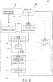
- Fig. 2 is a functional block diagram of a damping device 100 functioning as the control device for the robot according to the first embodiment.
- the damping device 100 is the control device for the robot that suppresses a bend and vibration ("bend and vibration" is hereinafter referred to as "vibration") that occurs in the arm 20 in the robot 200 during motion or during a stop.
- the damping device 100 includes encoders 50 (50a to 50f) functioning as angle sensors, an inertia sensor 60, and a calculation control unit 80.
- the encoders 50 (50a to 50f) detect respective rotation angles ⁇ 1 to ⁇ 6 of the motors included in the driving units 40a to 40f, i.e., driving amounts of the driving units 40.
- the inertia sensor 60 is a six-axis sensor and detects accelerations and angular velocities in an attached position. That is, the inertia sensor 60 detects accelerations (X", y", z") in X, Y, and Z axis directions in Fig. 1 and angular velocities (Rx', Ry', Rz') around the X, Y, and Z axes.
- the inertia sensor 60 is attached to a damping position, which is a target position for suppressing the vibration of the arm 20.
- the inertia sensor 60 is attached to the link 10f (i.e., a link at a distal end portion of the arm 20).
- the calculation control unit 80 includes first to fourth calculating units 81 to 84, a control unit 85, and a Jacobian-matrix calculating unit 87.
- the first calculating unit 81 calculates a first arm speed in the damping position from the accelerations and the angular velocities in the damping position detected by the inertia sensor 60.
- the second calculating unit 82 calculates a driving speed from the driving amounts of the driving units 40 detected by the encoders 50 and calculates an arm driving speed in the damping position on the basis of a Jacobian matrix J corresponding to the driving speed and the damping position.
- the Jacobian-matrix calculating unit 87 calculates the Jacobian matrix J on the basis of, for example, information concerning the driving amounts detected by the encoders 50.
- the third calculating unit 83 calculates a third arm speed in the damping position on the basis of the first arm speed calculated by the first calculating unit 81 and the second arm speed calculated by the second calculating unit 82.
- the third calculating unit 83 includes a filter 86 and removes a low frequency component equal to or lower than a predetermined frequency included in a waveform of the calculated third arm speed.
- the predetermined frequency is set to 1 Hz to remove a low frequency component equal to or lower than 1 Hz.
- the filter 86 is configured by an HPF (High Pass Filter).
- the fourth calculating unit 84 calculates, on the basis of the third arm speed calculated by the third calculating unit 83, a correction speed of each of the driving units 40 that drive the links 10 present between the robot main body 30 and the damping position according to an inverse Jacobian matrix J -1 .
- the Jacobian-matrix calculating unit 87 calculates the inverse Jacobian matrix J -1 on the basis of, for example, the information concerning the driving amounts detected by the encoders 50.
- the control unit 85 controls, on the basis of the correction speed calculated by the fourth calculating unit 84, the driving units 40 that drive the links 10 present between the robot main body 30 and the damping position.
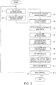
- Fig. 3 is a flowchart for explaining a damping method by the damping device 100 adopted as a control method for a robot according to this embodiment.
- the calculation control unit 80 and a damping method by the calculation control unit 80 are specifically explained concerning the link model of the robot 200 shown in Fig. 1 with reference to the flowchart of Fig. 3 .
- the calculation control unit 80 calculates the Jacobian matrix J corresponding to the damping position on the basis of the configuration specifications of the robot 200 (a coupling distance of the links, etc.), information concerning the damping position in the robot 200 to which the inertia sensor 60 is attached, the rotation angles ⁇ 1 to ⁇ 6 detected by the encoders 50 (50a to 50f), and the like (step S1).
- the calculation control unit 80 calculates an inverse matrix of the Jacobian matrix J to calculate the inverse Jacobian matrix J -1 (step S2).
- the Jacobian matrix J and the inverse Jacobian matrix J -1 satisfy a relational expression shown below.
- the calculation control unit 80 calculates, in the first calculating unit 81, first arm speeds (x 1 ', y 1 ', z 1 ', Rx 1 ', Ry 1 ', Rz 1 ') in the damping position from accelerations and angular velocities (x 1 ", y 1 ", z 1 ", Rx 1 ', Ry 1 ', Rz 1 ') in the damping position detected by the inertia sensor 60 (step S3) (step S4).
- the calculation control unit 80 calculates, in the second calculating unit 82, driving speeds ⁇ '( ⁇ ' 1 , ⁇ ' 2 , ⁇ ' 3 , ⁇ ' 4 , ⁇ ' 5 , ⁇ ' 6 ) from the driving amounts (rotation angles ⁇ 1 to ⁇ 6 ) of the driving units 40a to 40f detected by the encoders 50 (step S5) (step S6) and calculates second arm speeds (x 2 ', y 2 ', z 2 ', Rx 2 ', Ry 2 ', Rz 2 ') in the damping position on the basis of the driving speeds and the Jacobian matrix J corresponding to the damping position (step S7).
- the calculation control unit 80 calculates, in the third calculating unit 83, differences between the first arm speeds calculated by the first calculating unit 81 and the second arm speeds calculated by the second calculating unit 82 and calculates third arm speeds (x 1 ', -x 2 ', y 1 ', -y 2 ', z 1 ', -z 2 ', Rx 1 ', -Rx 2 ', Ry 1 ', -Ry 2 ', Rz 1 ', -Rz 2 ') (step S8).
- the calculation control unit 80 removes, with the filter 86 included in the third calculating unit 83, low frequency components equal to or lower than a predetermined frequency included in waveforms of the calculated third arm speeds (step S9). Specifically, in this embodiment, low frequency components equal to or lower than 1 Hz are removed by the HPF.
- the calculation control unit 80 calculates, in the fourth calculating unit 84, correction speeds ⁇ 'r ( ⁇ 'r 1 to ⁇ 'r 6 ) for each of the driving units 40 that drive the links 10 present between the robot main body 30 and the damping position according to the inverse Jacobian matrix J -1 on the basis of the third arm speeds calculated by the third calculating unit 83 (step S10).
- the correction speeds ⁇ 'r ( ⁇ 'r 1 to ⁇ 'r 6 ) satisfy a relational expression shown below.
- the calculation control unit 80 applies, in the control unit 85, on the basis of the driving amounts (the rotation angles ⁇ 1 to ⁇ 6 ), the driving speeds ⁇ ', and the correction speeds ⁇ 'r, feedback control to the driving units 40 that drive the links 10 present between the robot main body 30 and the damping position (step S11). Specifically, the calculation control unit 80 controls the motors included in the respective driving units 40a to 40f to generate torque in a direction for cancelling the correction speeds ⁇ 'r ( ⁇ 'r 1 to ⁇ 'r 6 ) distributed to the respective driving units 40a to 40f.
- the calculation control unit 80 determines whether to end the control (step S12). When continuing the control of the robot, the calculation control unit 80 returns to step S1.
- the third arm speeds in the damping position are calculated on the basis of information concerning the first arm speeds obtained from the inertia sensor 60 and information concerning the second arm speeds obtained from the encoders 50.
- the correction speeds for each of driving units 40 that drive the links 10 present between the robot main body 30 and the damping position are calculated on the basis of the calculated third arm speeds.
- the arm driving speeds in the damping position obtained from the encoders 50 are speeds calculated from driving amounts controlled to follow a command (e.g. a command programmed in advance) for controlling the plurality of driving units 40. Therefore, the arm driving speeds are speeds including extremely few speed components due to vibration or the like that occurs in the arm 20 accompanying motion. That is, in the case of an ideal robot that is light in weight and high in rigidity and does not have a bend, vibration due to the bend, and the like, actual speeds of the arm 20 indicate ideal arm speeds.
- the first arm speeds obtained from the inertia sensor 60 are speeds detected according to an actual movement of the damping position where the inertia sensor 60 is attached. That is, the first arm speeds are speeds including speed components such as vibration that occurs accompanying actual motion because of a bend and the like of the arm 20 that does not have ideal rigidity. Therefore, it is possible to extract the speed components due to the vibration by evaluating differences between the first arm speeds and the second arm speeds . It is possible to achieve suppression of the vibration by distributing the extracted speed components of the vibration to the driving units 40, which drive the respective links 10, as the correction speeds to generate torque for suppressing the vibration.
- the damping device 100 further includes the filter 86 for removing the low frequency components equal to or lower than the predetermined frequency included in the waveforms of the third arm speeds, it is possible to more appropriately extract vibration components through the evaluation of the differences between the first arm speeds and the second arm speeds. Specifically, it is possible to reduce the influence of a wrong correction for suppressing the original motion of the arm 20, an offset error of the inertia sensor 60, and the like by removing the low frequency components of the third arm speeds.
- control device and the control method for the robot according to this embodiment it is possible to achieve further increases in accuracy, speed, and the like in the multi-joint robot.
- the third calculating unit 83 includes the filter 86 to remove the low frequency components equal to or lower than 1 Hz as the low frequency components equal to or lower than the predetermined frequency included in the waveforms of the calculated third arm speeds.
- the predetermined frequency does not always need to be 1 Hz. It is desirable to determine the predetermined frequency as appropriate according to a damping state of the damping position.
- the third calculating unit 83 does not always need to include the filter 86.
- the filter 86 can be omitted when there are no low frequency components to be removed in the calculated third arm speeds or when the low frequency components can be neglected.
- calculation control unit 80 calculates the Jacobian matrix J and the inverse Jacobian matrix J -1 in the Jacobian-matrix calculating unit 87 on the basis of, for example, the information concerning the driving amounts detected by the encoders 50.
- the calculation control unit 80 does not always need to calculate the Jacobian matrix J and the inverse Jacobian matrix J -1 during the operation of the robot 200.
- a control device and a control method for a robot according to a second embodiment are explained.
- components same as the components in the first embodiment are denoted by the same reference numerals and signs and redundant explanation of the components is omitted.
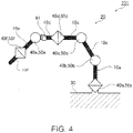
- Fig. 4 is a schematic diagram showing a link model of a robot 201 mounted with the control device for the robot according to the second embodiment.
- the robot 201 is a six-axis multi-joint robot same as the robot 200 mounted with a damping device 101 (not shown in the figure).
- the damping device 101 is the same as the damping device 100 except that a gyro sensor (hereinafter, inertia sensor 61) that detects angular velocities (Rx', Ry', Rz') of three axes is used as the inertia sensor.
- the inertia sensor 61 is attached to the link 10d. That is, whereas the inertia sensor 60 is attached to the link 10f to suppress vibration in the distal end portion of the arm 20 in the first embodiment, in this embodiment, the inertia sensor 61 is attached to the fourth link 10d and a position substantially in the middle of the arm 20 is set as a damping position.
- the inertia sensor 60 is the six-axis acceleration and angular velocity sensor in the first embodiment
- the gyro sensor that detects the angular velocities (Rx', Ry', Rz') of the three axes is used.
- the second embodiment is the same as the first embodiment.
- Feedback control for suppressing vibration in this embodiment is applied to the driving units present on the robot main body 30 from the damping position where the inertia sensor 61 is attached. That is, on the basis of angular velocity information of the three axes, the control is applied to the four driving units 40a to 40d having one more degree of freedom. In this way, in the case of the control with redundancy, the control is distributed according to a weighted pseudo-inverse matrix.
- J 1 # W -1 J 1 T J 1 T W ⁇ 1 J 1 T ⁇ 1
- J 1 # is a matrix for minimizing a weighted sum of squares of the correction speeds ⁇ 'r( ⁇ 'r 1 to ⁇ 'r 4 ) distributed to the respective driving units 40a to 40d calculated by the formula. That is, concerning a degree of freedom, movement for suppressing vibration is set to a minimum value.
- W represents a 4 ⁇ 4 weighing matrix. That is, values of the correction speeds ⁇ 'r distributed to the respective driving units 40a to 40d are weighted.
- the damping device 101 and the damping method are the same as the damping device 100 and the damping method according to the first embodiment except that the weighted pseudo-inverse matrix J 1 # is used instead of the inverse Jacobian matrix J -1 .
- the magnitude of the correction speed for each of the driving units 40 is distributed according to weighting for each of the driving units 40 set in advance, it is possible to perform more effective suppression control for vibration according to the specifications and the characteristics of the robot 201 or a load of work that the robot 201 is caused to perform (e.g., the weight of an object held by a robot hand) .
- a load of work that the robot 201 is caused to perform e.g., the weight of an object held by a robot hand
- it is possible to more effectively perform suppression of vibration by setting larger damping torque of the driving units 40 in a portion close to the robot main body 30.
- the object held by the robot hand changes and the weight changes in a series of motion of the robot 201, it is possible to more effectively perform the suppression of vibration.
- a control device and a control method for a robot according to a third embodiment are explained.
- components same as the components in the embodiments explained above are denoted by the same reference numerals and signs and redundant explanation of the components is omitted.
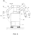
- Fig. 5 is a schematic diagram showing a link model of a robot 202 mounted with the control device of the robot according to the third embodiment.
- the robot 202 is a double-arm multi-joint robot mounted with a damping device 102 (not shown in the figure).
- the robot 202 includes two arms 21 forming seven-axis double arms, a revolving arm 22, the robot main body 30, and the damping device 102.
- seven links 11b to 11h are coupled in order via driving units 41b to 41h.
- a hand tool, a welding gun, a spray gun, or the like is attached as a hand unit.
- the revolving arm 22 includes a link 11a and a driving unit 41a.
- One end of the link 11a is coupled to the robot main body 30 via the driving unit 41a.
- the other end supports, via the two driving units 41b, the two arms 21 coupled to the respective driving units 41b. That is, the other end of the arm 21 is coupled to the revolving arm 22 via the driving unit 41b.
- the driving units 41a, 41b, 41d, 41f, and 41h include motors configured to drive to rotate shafts of the links 11a, 11b, 11d, 11f, and 11h coupled to the driving units 41a, 41b, 41d, 41f, and 41h.
- the driving units 41c, 41e, and 41g include motors configured to pivot the links 11c, 11e, and 11g coupled to the driving units 41c, 41e, and 41g to change coupling angles of the links 11c, 11e, and 11g.
- the driving units 41a to 41h respectively include encoders 50a to 50h configured to detect driving amounts of the driving units 41a to 41h (rotation angles of the motors) .
- the encoders 50 (50a to 50h) detect respective rotation angles ⁇ 1 to ⁇ 8 of the motors included in the driving units 41a to 41h.
- Inertia sensors 61 are attached to the respective links 11e of the arms 21.
- the damping device 102 is configured such that two damping devices 101 are processed in parallel.
- the damping device 102 instead of such a configuration (including the two damping devices 101 to process the two damping devices 101 in parallel), a method of time-sharing one damping device 101 for the respective arms 21 may be adopted. That is, the damping device 102 may be configured to independently apply processing by one damping device 101 to the two arms 21 while switching the processing.
- the state feedback control for suppressing vibration in this embodiment is not applied to the revolving arm 22 common to the respective arms 21. That is, the control is applied to the four driving units 41b to 41e on the basis of angular velocity information of three axes detected by the inertia sensor 61 included in each of the arms 21.
- the Jacobian matrix J 2 is a matrix reflecting five axes ( ⁇ 1 to ⁇ 5 ) of the driving units 41a to 41e. Therefore, the Jacobian matrix J 2 is given by a 3 ⁇ 5 matrix.
- J 3 # is a matrix for minimizing a weighted sum of squares of the correction speeds ⁇ 'r ( ⁇ 'r 2 to ⁇ 'r 5 ) distributed to the respective driving units 41b to 41e calculated by the formula. That is, as in the second embodiment, concerning a degree of freedom, movement for suppressing vibration is set to a minimum value.
- the respective kinds of processing are more simplified and processing speed is increased by excluding the driving unit from the target of the control. Therefore, it is possible to more efficiently perform the processing.
- a robot according to a fourth embodiment which is a more specific form of the robot in the embodiments explained above, is explained.
- components same as the components in the embodiments explained above are denoted by the same reference numerals and signs and redundant explanation of the components is omitted.
- Fig. 6 is a schematic diagram of a robot 203 according to the fourth embodiment.
- the robot 203 is a double-arm multi-joint robot mounted with the damping device 102.
- the robot 203 includes two arms 23, a revolving arm 24, hands 70, the robot main body 30, and the damping device 102.
- a link 13b and a link 13c are coupled via a driving unit 43c.
- the hand 70 is provided at one end of the arm 23 via a driving unit 43d.
- the hand 70 has a function of gripping a predetermined object.
- the revolving arm 24 includes a link 13a and a driving unit 43a.
- One end of the link 13a is coupled to the robot main body 30 via the driving unit 43a.
- the other end supports, via two driving units 43b, the two arms 23 coupled to the respective driving units 43b. That is, the other end of the arm 23 is coupled to the revolving arm 24 via the driving unit 43b.
- the driving units 43b and 43c include motors configured to pivot the links 13b and 13c coupled to the driving units 43b and 43c to change coupling angles of the links 13b and 13c.
- the driving units 43a and 43d include motors configured to drive to rotate shafts of the link 13a and the hand 70 respectively coupled to the driving units 43a and 43d.
- the respective driving units 43a to 43d include encoders 50a to 50d configured to detect driving amounts of the driving units 43a to 43d (rotation angles of the motors) .
- the inertia sensors 61 are attached to the respective links 13c of the arms 23.
- the robot main body 30 supports the revolving arm 24 and supports the two arms 23 via the revolving arms 24.
- the robot main body 30 is set on the floor or the like.
- a robot controller 31 including the damping device 102 is provided on the inside of the robot main body 30.
- the robot controller 31 includes a control device such as the damping device 102 and performs control of the entire robot 203.
- the damping device 102 is mounted, as in the control method for the robot explained above, it is possible to suppress vibration that occurs in the arm 23 in motion.
- the robot with a function of the multi-joint robot further improved to be capable of flexibly performing highly accurate and high-speed motion. For example, when a spray gun or the like is attached to the hand 70 to paint a painting target, if painting unevenness due to vibration in the arm 23 tends to occur, it is possible to reduce the painting unevenness by suppressing the vibration.
Landscapes
- Engineering & Computer Science (AREA)
- Robotics (AREA)
- Mechanical Engineering (AREA)
- Manipulator (AREA)
Applications Claiming Priority (1)
| Application Number | Priority Date | Filing Date | Title |
|---|---|---|---|
| JP2012169285A JP6083145B2 (ja) | 2012-07-31 | 2012-07-31 | ロボットの制御装置、およびロボット |
Publications (3)
| Publication Number | Publication Date |
|---|---|
| EP2692488A2 EP2692488A2 (en) | 2014-02-05 |
| EP2692488A3 EP2692488A3 (en) | 2017-04-12 |
| EP2692488B1 true EP2692488B1 (en) | 2018-10-17 |
Family
ID=48875612
Family Applications (1)
| Application Number | Title | Priority Date | Filing Date |
|---|---|---|---|
| EP13178508.1A Active EP2692488B1 (en) | 2012-07-31 | 2013-07-30 | Control device and control method for robot and the robot |
Country Status (6)
| Country | Link |
|---|---|
| US (2) | US9095979B2 (ja) |
| EP (1) | EP2692488B1 (ja) |
| JP (1) | JP6083145B2 (ja) |
| KR (1) | KR20140016839A (ja) |
| CN (1) | CN103568013B (ja) |
| TW (1) | TWI577515B (ja) |
Cited By (1)
| Publication number | Priority date | Publication date | Assignee | Title |
|---|---|---|---|---|
| DE102019108804B4 (de) | 2018-04-06 | 2021-07-29 | Fanuc Corporation | Robotersystem zur durchführung einer lernkontrolle unter verwendung von motorgeber und sensor |
Families Citing this family (32)
| Publication number | Priority date | Publication date | Assignee | Title |
|---|---|---|---|---|
| JP5652042B2 (ja) | 2010-08-06 | 2015-01-14 | セイコーエプソン株式会社 | ロボット装置、ロボット装置の制御方法およびプログラム |
| JP2014034101A (ja) * | 2012-08-10 | 2014-02-24 | Toshiba Corp | ロボット制御装置 |
| JP6111562B2 (ja) * | 2012-08-31 | 2017-04-12 | セイコーエプソン株式会社 | ロボット |
| JP6248544B2 (ja) * | 2013-10-30 | 2017-12-20 | セイコーエプソン株式会社 | ロボット、制御装置、ロボットシステム |
| JP2015150630A (ja) * | 2014-02-13 | 2015-08-24 | セイコーエプソン株式会社 | ロボット |
| US9868209B2 (en) | 2013-12-02 | 2018-01-16 | Seiko Epson Corporation | Robot |
| US9718187B2 (en) * | 2014-06-11 | 2017-08-01 | Canon Kabushiki Kaisha | Robot controlling method, robot apparatus, program, recording medium, and method for manufacturing assembly component |
| US9873198B2 (en) * | 2014-10-06 | 2018-01-23 | The Johns Hopkins University | Active vibration damping device |
| CN104537944B (zh) * | 2014-12-30 | 2017-09-26 | 浙江钱江机器人有限公司 | 一种六轴机器人的六连杆示教装置 |
| JP6496167B2 (ja) * | 2015-03-19 | 2019-04-03 | オークマ株式会社 | タンデム位置制御装置 |
| JP6575200B2 (ja) * | 2015-07-27 | 2019-09-18 | セイコーエプソン株式会社 | ロボット、制御装置およびロボットシステム |
| JP6088601B2 (ja) * | 2015-08-10 | 2017-03-01 | ファナック株式会社 | 走行軸付きロボットにおけるツール先端の振れを抑制するロボット制御装置 |
| JP6771288B2 (ja) * | 2016-02-17 | 2020-10-21 | 株式会社神戸製鋼所 | 溶接装置及び溶接装置の制御方法 |
| CN105953792B (zh) * | 2016-04-27 | 2018-08-31 | 宁夏巨能机器人系统有限公司 | 一种多关节机器人定位精度的检测装置及其检测方法 |
| JP2017196704A (ja) * | 2016-04-28 | 2017-11-02 | セイコーエプソン株式会社 | 可動部の振動測定方法、ロボットの振動測定方法および制御装置 |
| US10350754B2 (en) * | 2016-09-27 | 2019-07-16 | Denso Wave Incorporated | Control device for robot |
| JP6711536B2 (ja) * | 2016-10-28 | 2020-06-17 | アズビル株式会社 | 外力検出方法 |
| JP6895242B2 (ja) * | 2016-11-25 | 2021-06-30 | 株式会社東芝 | ロボット制御装置、ロボット制御方法及びピッキング装置 |
| CN106863303A (zh) * | 2017-03-04 | 2017-06-20 | 安凯 | 一种焊接机械手及其路径学习方法 |
| WO2018221472A1 (ja) * | 2017-06-01 | 2018-12-06 | パナソニック インテレクチュアル プロパティ コーポレーション オブ アメリカ | 受信装置および受信方法 |
| WO2019002898A1 (en) * | 2017-06-30 | 2019-01-03 | Siemens Industry Software Ltd. | METHOD AND SYSTEM FOR DETERMINING JOINT VALUES OF AN EXTERNAL AXIS FOR ROBOT MANUFACTURE |
| JP7007839B2 (ja) * | 2017-08-31 | 2022-01-25 | 川崎重工業株式会社 | 多関節ロボット |
| CN109591050A (zh) * | 2017-09-30 | 2019-04-09 | 西门子公司 | 安全跟踪系统、装置、方法、存储介质及安全系统 |
| CN108638056A (zh) * | 2018-04-13 | 2018-10-12 | 华南理工大学 | 基于柔体动力学模型的机器人关节振动分析与抑制方法 |
| JP7141847B2 (ja) * | 2018-05-11 | 2022-09-26 | 川崎重工業株式会社 | 撓み量推定装置、ロボット制御装置、及び撓み量推定方法 |
| US11597083B2 (en) * | 2018-12-17 | 2023-03-07 | Canon Kabushiki Kaisha | Robot apparatus, robot system, control method of robot apparatus, product manufacturing method using robot apparatus, and storage medium |
| AU2019430399A1 (en) | 2019-02-22 | 2021-10-21 | Covidien Lp | Input shaper for robotic surgical system |
| TWI701122B (zh) * | 2019-07-15 | 2020-08-11 | 由田新技股份有限公司 | 多軸機械手臂系統及其路徑規劃方法 |
| CN110549337A (zh) * | 2019-08-30 | 2019-12-10 | 上海有个机器人有限公司 | 一种配送机器人控制系统 |
| TWI742990B (zh) | 2021-01-19 | 2021-10-11 | 財團法人工業技術研究院 | 機械手臂系統、其控制方法及其電腦程式產品 |
| JP2022157882A (ja) * | 2021-03-31 | 2022-10-14 | セイコーエプソン株式会社 | ロボットの制御方法、ロボットシステムおよびロボット制御プログラム |
| KR102701645B1 (ko) * | 2021-12-09 | 2024-09-03 | 주식회사 알피 | 진동 저감 주행형 고소 도장 로봇 |
Family Cites Families (30)
| Publication number | Priority date | Publication date | Assignee | Title |
|---|---|---|---|---|
| JP2521458B2 (ja) * | 1987-02-17 | 1996-08-07 | 株式会社ダイヘン | マニピユレ−タの防振制御装置 |
| JP2521315B2 (ja) * | 1987-12-28 | 1996-08-07 | 三菱重工業株式会社 | 柔軟構造物の振動制御装置 |
| JPH07314360A (ja) | 1994-05-31 | 1995-12-05 | Ishikawajima Harima Heavy Ind Co Ltd | カメラ操作ロボット |
| JPH106261A (ja) | 1996-06-18 | 1998-01-13 | Sony Corp | ロボット制御装置 |
| JP3442941B2 (ja) * | 1996-09-30 | 2003-09-02 | 株式会社東芝 | ロボットの振動抑制制御装置およびその制御方法 |
| US6508122B1 (en) | 1999-09-16 | 2003-01-21 | American Gnc Corporation | Microelectromechanical system for measuring angular rate |
| US6569109B2 (en) | 2000-02-04 | 2003-05-27 | Olympus Optical Co., Ltd. | Ultrasonic operation apparatus for performing follow-up control of resonance frequency drive of ultrasonic oscillator by digital PLL system using DDS (direct digital synthesizer) |
| DE60100372T2 (de) * | 2000-02-10 | 2003-12-04 | Fanuc Ltd., Yamanashi | Steuervorrichtung für eine Maschine |
| CN1344908A (zh) | 2000-09-15 | 2002-04-17 | 林清芳 | 测量角速率的微机电系统 |
| JP2002304219A (ja) | 2001-04-04 | 2002-10-18 | Yaskawa Electric Corp | モータ制御装置およびメカ特性測定方法 |
| JP2005212054A (ja) | 2004-01-30 | 2005-08-11 | Keio Gijuku | 力検出方法及び装置並びに力検出機能を備えた制御装置 |
| JP3883544B2 (ja) | 2004-02-27 | 2007-02-21 | 株式会社東芝 | ロボット制御装置およびロボットの制御方法 |
| CN1984756B (zh) | 2004-07-13 | 2011-12-07 | 松下电器产业株式会社 | 物品保持系统、机器人以及机器人控制方法 |
| WO2006022201A1 (ja) * | 2004-08-25 | 2006-03-02 | Kabushiki Kaisha Yaskawa Denki | ロボットの評価システム及び評価方法 |
| WO2006129612A1 (ja) | 2005-05-31 | 2006-12-07 | Mitsubishi Electric Corporation | 電動機制御装置 |
| CN101043198A (zh) * | 2006-03-22 | 2007-09-26 | Juki株式会社 | 电子部件搭载装置 |
| AT504257B1 (de) * | 2006-09-18 | 2008-06-15 | Univ Linz | Vorrichtung zum steuern eines roboterarmes |
| JP4267027B2 (ja) * | 2006-12-07 | 2009-05-27 | ファナック株式会社 | ロボット制御装置 |
| JP4565034B2 (ja) | 2008-12-16 | 2010-10-20 | ファナック株式会社 | イナーシャ推定を行う制御装置及び制御システム |
| JP4957753B2 (ja) | 2009-06-15 | 2012-06-20 | セイコーエプソン株式会社 | ロボット、搬送装置、及び慣性センサーを用いた制御方法 |
| DE102009032278B4 (de) * | 2009-07-08 | 2021-03-04 | Kuka Roboter Gmbh | Verfahren und eine Vorrichtung zum Betreiben eines Manipulators |
| JP5353581B2 (ja) | 2009-09-10 | 2013-11-27 | セイコーエプソン株式会社 | ロボット |
| JP5417161B2 (ja) * | 2009-12-28 | 2014-02-12 | 川崎重工業株式会社 | ロボットの制振方法およびロボットの制御装置 |
| JP2011161562A (ja) * | 2010-02-09 | 2011-08-25 | Yaskawa Electric Corp | 無線伝送装置とそれを用いたロボットの振動抑制制御装置およびロボット制御装置 |
| JP5645423B2 (ja) | 2010-02-23 | 2014-12-24 | キヤノン株式会社 | 回転駆動装置及びロボットアーム |
| US8762091B1 (en) * | 2010-06-08 | 2014-06-24 | Thales Visionix, Inc. | Inertial measurement system |
| JP5652042B2 (ja) * | 2010-08-06 | 2015-01-14 | セイコーエプソン株式会社 | ロボット装置、ロボット装置の制御方法およびプログラム |
| CN103270692B (zh) * | 2010-12-20 | 2016-01-20 | 三菱电机株式会社 | 马达控制装置 |
| JP5848873B2 (ja) * | 2011-01-05 | 2016-01-27 | 株式会社ミツトヨ | 制御装置、および測定装置 |
| US8886359B2 (en) * | 2011-05-17 | 2014-11-11 | Fanuc Corporation | Robot and spot welding robot with learning control function |
-
2012
- 2012-07-31 JP JP2012169285A patent/JP6083145B2/ja active Active
-
2013
- 2013-07-26 TW TW102126977A patent/TWI577515B/zh active
- 2013-07-29 US US13/953,120 patent/US9095979B2/en active Active
- 2013-07-29 CN CN201310322411.8A patent/CN103568013B/zh active Active
- 2013-07-30 EP EP13178508.1A patent/EP2692488B1/en active Active
- 2013-07-30 KR KR1020130090028A patent/KR20140016839A/ko not_active Application Discontinuation
-
2015
- 2015-07-02 US US14/790,778 patent/US20150306765A1/en not_active Abandoned
Non-Patent Citations (1)
| Title |
|---|
| None * |
Cited By (1)
| Publication number | Priority date | Publication date | Assignee | Title |
|---|---|---|---|---|
| DE102019108804B4 (de) | 2018-04-06 | 2021-07-29 | Fanuc Corporation | Robotersystem zur durchführung einer lernkontrolle unter verwendung von motorgeber und sensor |
Also Published As
| Publication number | Publication date |
|---|---|
| KR20140016839A (ko) | 2014-02-10 |
| US20150306765A1 (en) | 2015-10-29 |
| TWI577515B (zh) | 2017-04-11 |
| JP6083145B2 (ja) | 2017-02-22 |
| CN103568013B (zh) | 2016-05-04 |
| CN103568013A (zh) | 2014-02-12 |
| US9095979B2 (en) | 2015-08-04 |
| EP2692488A2 (en) | 2014-02-05 |
| EP2692488A3 (en) | 2017-04-12 |
| TW201410418A (zh) | 2014-03-16 |
| JP2014028407A (ja) | 2014-02-13 |
| US20140039678A1 (en) | 2014-02-06 |
Similar Documents
| Publication | Publication Date | Title |
|---|---|---|
| EP2692488B1 (en) | Control device and control method for robot and the robot | |
| JP5327722B2 (ja) | ロボットの負荷推定装置及び負荷推定方法 | |
| JP5417161B2 (ja) | ロボットの制振方法およびロボットの制御装置 | |
| CN103213134B (zh) | 机械手的控制方法和机械手 | |
| CN104626152B (zh) | 工业机器人主动柔顺控制方法及装置 | |
| US8335591B2 (en) | Robot apparatus and method of controlling the same | |
| KR20120028837A (ko) | 감속기의 이상 판정 방법, 이상 판정 장치 및 로봇 시스템 | |
| JP6834125B2 (ja) | ロボット制御装置、ロボット制御方法 | |
| JP6392825B2 (ja) | 学習制御機能を備えたロボット制御装置 | |
| EP2404712A1 (en) | A dual arm robot and a method for controlling a dual arm robot | |
| JP3766484B2 (ja) | 多関節ロボットの負荷重量及び負荷重心位置の自動算出方法 | |
| CN112405566A (zh) | 机器人控制装置 | |
| JP5929150B2 (ja) | ロボット装置 | |
| Groome | Force feedback steering of a teleoperator system. | |
| JP6565622B2 (ja) | ロボットシステム及びロボット制御方法 | |
| JP2016221653A (ja) | ロボット制御装置およびロボットシステム | |
| JPH079608B2 (ja) | ロボツトの制御方法及びその装置 | |
| JP2016179523A (ja) | ロボット制御装置およびロボットシステム | |
| JPH04343690A (ja) | 多関節マニピュレータの関節摩擦補償方法 | |
| Fan et al. | Improvement of dynamic transparency of haptic devices by using spring balance | |
| CN218875470U (zh) | 作业装置及其碰撞保护结构 | |
| KR102645792B1 (ko) | 로봇 매니퓰레이터의 충격량을 산출하는 검출장치 및 방법 | |
| JPH04256590A (ja) | ロボットの制御方法 | |
| CN115502960A (zh) | 末端组件、作业装置及其控制方法 | |
| Konno et al. | Vibration suppression control of spatial flexible manipulators |
Legal Events
| Date | Code | Title | Description |
|---|---|---|---|
| AK | Designated contracting states |
Kind code of ref document: A2 Designated state(s): AL AT BE BG CH CY CZ DE DK EE ES FI FR GB GR HR HU IE IS IT LI LT LU LV MC MK MT NL NO PL PT RO RS SE SI SK SM TR |
|
| AX | Request for extension of the european patent |
Extension state: BA ME |
|
| PUAI | Public reference made under article 153(3) epc to a published international application that has entered the european phase |
Free format text: ORIGINAL CODE: 0009012 |
|
| PUAL | Search report despatched |
Free format text: ORIGINAL CODE: 0009013 |
|
| AK | Designated contracting states |
Kind code of ref document: A3 Designated state(s): AL AT BE BG CH CY CZ DE DK EE ES FI FR GB GR HR HU IE IS IT LI LT LU LV MC MK MT NL NO PL PT RO RS SE SI SK SM TR |
|
| AX | Request for extension of the european patent |
Extension state: BA ME |
|
| RIC1 | Information provided on ipc code assigned before grant |
Ipc: B25J 9/16 20060101AFI20170303BHEP Ipc: G05B 19/404 20060101ALN20170303BHEP |
|
| STAA | Information on the status of an ep patent application or granted ep patent |
Free format text: STATUS: REQUEST FOR EXAMINATION WAS MADE |
|
| 17P | Request for examination filed |
Effective date: 20170720 |
|
| RBV | Designated contracting states (corrected) |
Designated state(s): AL AT BE BG CH CY CZ DE DK EE ES FI FR GB GR HR HU IE IS IT LI LT LU LV MC MK MT NL NO PL PT RO RS SE SI SK SM TR |
|
| RIC1 | Information provided on ipc code assigned before grant |
Ipc: G05B 19/404 20060101ALN20180329BHEP Ipc: B25J 9/16 20060101AFI20180329BHEP |
|
| GRAP | Despatch of communication of intention to grant a patent |
Free format text: ORIGINAL CODE: EPIDOSNIGR1 |
|
| STAA | Information on the status of an ep patent application or granted ep patent |
Free format text: STATUS: GRANT OF PATENT IS INTENDED |
|
| RIC1 | Information provided on ipc code assigned before grant |
Ipc: B25J 9/16 20060101AFI20180423BHEP Ipc: G05B 19/404 20060101ALN20180423BHEP |
|
| INTG | Intention to grant announced |
Effective date: 20180523 |
|
| GRAJ | Information related to disapproval of communication of intention to grant by the applicant or resumption of examination proceedings by the epo deleted |
Free format text: ORIGINAL CODE: EPIDOSDIGR1 |
|
| STAA | Information on the status of an ep patent application or granted ep patent |
Free format text: STATUS: REQUEST FOR EXAMINATION WAS MADE |
|
| GRAR | Information related to intention to grant a patent recorded |
Free format text: ORIGINAL CODE: EPIDOSNIGR71 |
|
| GRAS | Grant fee paid |
Free format text: ORIGINAL CODE: EPIDOSNIGR3 |
|
| STAA | Information on the status of an ep patent application or granted ep patent |
Free format text: STATUS: GRANT OF PATENT IS INTENDED |
|
| INTC | Intention to grant announced (deleted) | ||
| GRAA | (expected) grant |
Free format text: ORIGINAL CODE: 0009210 |
|
| STAA | Information on the status of an ep patent application or granted ep patent |
Free format text: STATUS: THE PATENT HAS BEEN GRANTED |
|
| RIC1 | Information provided on ipc code assigned before grant |
Ipc: G05B 19/404 20060101ALN20180828BHEP Ipc: B25J 9/16 20060101AFI20180828BHEP |
|
| INTG | Intention to grant announced |
Effective date: 20180905 |
|
| AK | Designated contracting states |
Kind code of ref document: B1 Designated state(s): AL AT BE BG CH CY CZ DE DK EE ES FI FR GB GR HR HU IE IS IT LI LT LU LV MC MK MT NL NO PL PT RO RS SE SI SK SM TR |
|
| REG | Reference to a national code |
Ref country code: GB Ref legal event code: FG4D |
|
| REG | Reference to a national code |
Ref country code: CH Ref legal event code: EP |
|
| REG | Reference to a national code |
Ref country code: IE Ref legal event code: FG4D |
|
| REG | Reference to a national code |
Ref country code: DE Ref legal event code: R096 Ref document number: 602013045138 Country of ref document: DE Ref country code: AT Ref legal event code: REF Ref document number: 1053443 Country of ref document: AT Kind code of ref document: T Effective date: 20181115 |
|
| REG | Reference to a national code |
Ref country code: NL Ref legal event code: MP Effective date: 20181017 |
|
| REG | Reference to a national code |
Ref country code: LT Ref legal event code: MG4D |
|
| REG | Reference to a national code |
Ref country code: AT Ref legal event code: MK05 Ref document number: 1053443 Country of ref document: AT Kind code of ref document: T Effective date: 20181017 |
|
| PG25 | Lapsed in a contracting state [announced via postgrant information from national office to epo] |
Ref country code: NL Free format text: LAPSE BECAUSE OF FAILURE TO SUBMIT A TRANSLATION OF THE DESCRIPTION OR TO PAY THE FEE WITHIN THE PRESCRIBED TIME-LIMIT Effective date: 20181017 |
|
| PG25 | Lapsed in a contracting state [announced via postgrant information from national office to epo] |
Ref country code: BG Free format text: LAPSE BECAUSE OF FAILURE TO SUBMIT A TRANSLATION OF THE DESCRIPTION OR TO PAY THE FEE WITHIN THE PRESCRIBED TIME-LIMIT Effective date: 20190117 Ref country code: LT Free format text: LAPSE BECAUSE OF FAILURE TO SUBMIT A TRANSLATION OF THE DESCRIPTION OR TO PAY THE FEE WITHIN THE PRESCRIBED TIME-LIMIT Effective date: 20181017 Ref country code: NO Free format text: LAPSE BECAUSE OF FAILURE TO SUBMIT A TRANSLATION OF THE DESCRIPTION OR TO PAY THE FEE WITHIN THE PRESCRIBED TIME-LIMIT Effective date: 20190117 Ref country code: IS Free format text: LAPSE BECAUSE OF FAILURE TO SUBMIT A TRANSLATION OF THE DESCRIPTION OR TO PAY THE FEE WITHIN THE PRESCRIBED TIME-LIMIT Effective date: 20190217 Ref country code: FI Free format text: LAPSE BECAUSE OF FAILURE TO SUBMIT A TRANSLATION OF THE DESCRIPTION OR TO PAY THE FEE WITHIN THE PRESCRIBED TIME-LIMIT Effective date: 20181017 Ref country code: LV Free format text: LAPSE BECAUSE OF FAILURE TO SUBMIT A TRANSLATION OF THE DESCRIPTION OR TO PAY THE FEE WITHIN THE PRESCRIBED TIME-LIMIT Effective date: 20181017 Ref country code: PL Free format text: LAPSE BECAUSE OF FAILURE TO SUBMIT A TRANSLATION OF THE DESCRIPTION OR TO PAY THE FEE WITHIN THE PRESCRIBED TIME-LIMIT Effective date: 20181017 Ref country code: HR Free format text: LAPSE BECAUSE OF FAILURE TO SUBMIT A TRANSLATION OF THE DESCRIPTION OR TO PAY THE FEE WITHIN THE PRESCRIBED TIME-LIMIT Effective date: 20181017 Ref country code: ES Free format text: LAPSE BECAUSE OF FAILURE TO SUBMIT A TRANSLATION OF THE DESCRIPTION OR TO PAY THE FEE WITHIN THE PRESCRIBED TIME-LIMIT Effective date: 20181017 Ref country code: AT Free format text: LAPSE BECAUSE OF FAILURE TO SUBMIT A TRANSLATION OF THE DESCRIPTION OR TO PAY THE FEE WITHIN THE PRESCRIBED TIME-LIMIT Effective date: 20181017 |
|
| PG25 | Lapsed in a contracting state [announced via postgrant information from national office to epo] |
Ref country code: PT Free format text: LAPSE BECAUSE OF FAILURE TO SUBMIT A TRANSLATION OF THE DESCRIPTION OR TO PAY THE FEE WITHIN THE PRESCRIBED TIME-LIMIT Effective date: 20190217 Ref country code: GR Free format text: LAPSE BECAUSE OF FAILURE TO SUBMIT A TRANSLATION OF THE DESCRIPTION OR TO PAY THE FEE WITHIN THE PRESCRIBED TIME-LIMIT Effective date: 20190118 Ref country code: SE Free format text: LAPSE BECAUSE OF FAILURE TO SUBMIT A TRANSLATION OF THE DESCRIPTION OR TO PAY THE FEE WITHIN THE PRESCRIBED TIME-LIMIT Effective date: 20181017 Ref country code: RS Free format text: LAPSE BECAUSE OF FAILURE TO SUBMIT A TRANSLATION OF THE DESCRIPTION OR TO PAY THE FEE WITHIN THE PRESCRIBED TIME-LIMIT Effective date: 20181017 Ref country code: AL Free format text: LAPSE BECAUSE OF FAILURE TO SUBMIT A TRANSLATION OF THE DESCRIPTION OR TO PAY THE FEE WITHIN THE PRESCRIBED TIME-LIMIT Effective date: 20181017 |
|
| REG | Reference to a national code |
Ref country code: DE Ref legal event code: R097 Ref document number: 602013045138 Country of ref document: DE |
|
| PG25 | Lapsed in a contracting state [announced via postgrant information from national office to epo] |
Ref country code: CZ Free format text: LAPSE BECAUSE OF FAILURE TO SUBMIT A TRANSLATION OF THE DESCRIPTION OR TO PAY THE FEE WITHIN THE PRESCRIBED TIME-LIMIT Effective date: 20181017 Ref country code: DK Free format text: LAPSE BECAUSE OF FAILURE TO SUBMIT A TRANSLATION OF THE DESCRIPTION OR TO PAY THE FEE WITHIN THE PRESCRIBED TIME-LIMIT Effective date: 20181017 Ref country code: IT Free format text: LAPSE BECAUSE OF FAILURE TO SUBMIT A TRANSLATION OF THE DESCRIPTION OR TO PAY THE FEE WITHIN THE PRESCRIBED TIME-LIMIT Effective date: 20181017 |
|
| PLBE | No opposition filed within time limit |
Free format text: ORIGINAL CODE: 0009261 |
|
| STAA | Information on the status of an ep patent application or granted ep patent |
Free format text: STATUS: NO OPPOSITION FILED WITHIN TIME LIMIT |
|
| PG25 | Lapsed in a contracting state [announced via postgrant information from national office to epo] |
Ref country code: RO Free format text: LAPSE BECAUSE OF FAILURE TO SUBMIT A TRANSLATION OF THE DESCRIPTION OR TO PAY THE FEE WITHIN THE PRESCRIBED TIME-LIMIT Effective date: 20181017 Ref country code: SK Free format text: LAPSE BECAUSE OF FAILURE TO SUBMIT A TRANSLATION OF THE DESCRIPTION OR TO PAY THE FEE WITHIN THE PRESCRIBED TIME-LIMIT Effective date: 20181017 Ref country code: SM Free format text: LAPSE BECAUSE OF FAILURE TO SUBMIT A TRANSLATION OF THE DESCRIPTION OR TO PAY THE FEE WITHIN THE PRESCRIBED TIME-LIMIT Effective date: 20181017 Ref country code: EE Free format text: LAPSE BECAUSE OF FAILURE TO SUBMIT A TRANSLATION OF THE DESCRIPTION OR TO PAY THE FEE WITHIN THE PRESCRIBED TIME-LIMIT Effective date: 20181017 |
|
| 26N | No opposition filed |
Effective date: 20190718 |
|
| PG25 | Lapsed in a contracting state [announced via postgrant information from national office to epo] |
Ref country code: SI Free format text: LAPSE BECAUSE OF FAILURE TO SUBMIT A TRANSLATION OF THE DESCRIPTION OR TO PAY THE FEE WITHIN THE PRESCRIBED TIME-LIMIT Effective date: 20181017 |
|
| PG25 | Lapsed in a contracting state [announced via postgrant information from national office to epo] |
Ref country code: MC Free format text: LAPSE BECAUSE OF FAILURE TO SUBMIT A TRANSLATION OF THE DESCRIPTION OR TO PAY THE FEE WITHIN THE PRESCRIBED TIME-LIMIT Effective date: 20181017 |
|
| REG | Reference to a national code |
Ref country code: CH Ref legal event code: PL |
|
| GBPC | Gb: european patent ceased through non-payment of renewal fee |
Effective date: 20190730 |
|
| PG25 | Lapsed in a contracting state [announced via postgrant information from national office to epo] |
Ref country code: TR Free format text: LAPSE BECAUSE OF FAILURE TO SUBMIT A TRANSLATION OF THE DESCRIPTION OR TO PAY THE FEE WITHIN THE PRESCRIBED TIME-LIMIT Effective date: 20181017 |
|
| REG | Reference to a national code |
Ref country code: BE Ref legal event code: MM Effective date: 20190731 |
|
| PG25 | Lapsed in a contracting state [announced via postgrant information from national office to epo] |
Ref country code: GB Free format text: LAPSE BECAUSE OF NON-PAYMENT OF DUE FEES Effective date: 20190730 |
|
| PG25 | Lapsed in a contracting state [announced via postgrant information from national office to epo] |
Ref country code: CH Free format text: LAPSE BECAUSE OF NON-PAYMENT OF DUE FEES Effective date: 20190731 Ref country code: LI Free format text: LAPSE BECAUSE OF NON-PAYMENT OF DUE FEES Effective date: 20190731 Ref country code: LU Free format text: LAPSE BECAUSE OF NON-PAYMENT OF DUE FEES Effective date: 20190730 Ref country code: BE Free format text: LAPSE BECAUSE OF NON-PAYMENT OF DUE FEES Effective date: 20190731 |
|
| PG25 | Lapsed in a contracting state [announced via postgrant information from national office to epo] |
Ref country code: FR Free format text: LAPSE BECAUSE OF NON-PAYMENT OF DUE FEES Effective date: 20190731 |
|
| PG25 | Lapsed in a contracting state [announced via postgrant information from national office to epo] |
Ref country code: IE Free format text: LAPSE BECAUSE OF NON-PAYMENT OF DUE FEES Effective date: 20190730 |
|
| PG25 | Lapsed in a contracting state [announced via postgrant information from national office to epo] |
Ref country code: CY Free format text: LAPSE BECAUSE OF FAILURE TO SUBMIT A TRANSLATION OF THE DESCRIPTION OR TO PAY THE FEE WITHIN THE PRESCRIBED TIME-LIMIT Effective date: 20181017 |
|
| PG25 | Lapsed in a contracting state [announced via postgrant information from national office to epo] |
Ref country code: MT Free format text: LAPSE BECAUSE OF FAILURE TO SUBMIT A TRANSLATION OF THE DESCRIPTION OR TO PAY THE FEE WITHIN THE PRESCRIBED TIME-LIMIT Effective date: 20181017 Ref country code: HU Free format text: LAPSE BECAUSE OF FAILURE TO SUBMIT A TRANSLATION OF THE DESCRIPTION OR TO PAY THE FEE WITHIN THE PRESCRIBED TIME-LIMIT; INVALID AB INITIO Effective date: 20130730 |
|
| PG25 | Lapsed in a contracting state [announced via postgrant information from national office to epo] |
Ref country code: MK Free format text: LAPSE BECAUSE OF FAILURE TO SUBMIT A TRANSLATION OF THE DESCRIPTION OR TO PAY THE FEE WITHIN THE PRESCRIBED TIME-LIMIT Effective date: 20181017 |
|
| PGFP | Annual fee paid to national office [announced via postgrant information from national office to epo] |
Ref country code: DE Payment date: 20230607 Year of fee payment: 11 |