EP2669822A2 - Kommunikationsendgerät, Anzeigeverfahren und Computerprogrammprodukt - Google Patents
Kommunikationsendgerät, Anzeigeverfahren und Computerprogrammprodukt Download PDFInfo
- Publication number
- EP2669822A2 EP2669822A2 EP20130169681 EP13169681A EP2669822A2 EP 2669822 A2 EP2669822 A2 EP 2669822A2 EP 20130169681 EP20130169681 EP 20130169681 EP 13169681 A EP13169681 A EP 13169681A EP 2669822 A2 EP2669822 A2 EP 2669822A2
- Authority
- EP
- European Patent Office
- Prior art keywords
- predetermined
- image
- region
- information
- unit
- Prior art date
- Legal status (The legal status is an assumption and is not a legal conclusion. Google has not performed a legal analysis and makes no representation as to the accuracy of the status listed.)
- Ceased
Links
Images














Classifications
-
- G—PHYSICS
- G06—COMPUTING OR CALCULATING; COUNTING
- G06F—ELECTRIC DIGITAL DATA PROCESSING
- G06F16/00—Information retrieval; Database structures therefor; File system structures therefor
- G06F16/50—Information retrieval; Database structures therefor; File system structures therefor of still image data
- G06F16/54—Browsing; Visualisation therefor
-
- H—ELECTRICITY
- H04—ELECTRIC COMMUNICATION TECHNIQUE
- H04N—PICTORIAL COMMUNICATION, e.g. TELEVISION
- H04N23/00—Cameras or camera modules comprising electronic image sensors; Control thereof
- H04N23/60—Control of cameras or camera modules
- H04N23/698—Control of cameras or camera modules for achieving an enlarged field of view, e.g. panoramic image capture
-
- G—PHYSICS
- G06—COMPUTING OR CALCULATING; COUNTING
- G06F—ELECTRIC DIGITAL DATA PROCESSING
- G06F3/00—Input arrangements for transferring data to be processed into a form capable of being handled by the computer; Output arrangements for transferring data from processing unit to output unit, e.g. interface arrangements
- G06F3/01—Input arrangements or combined input and output arrangements for interaction between user and computer
- G06F3/048—Interaction techniques based on graphical user interfaces [GUI]
- G06F3/0481—Interaction techniques based on graphical user interfaces [GUI] based on specific properties of the displayed interaction object or a metaphor-based environment, e.g. interaction with desktop elements like windows or icons, or assisted by a cursor's changing behaviour or appearance
- G06F3/04817—Interaction techniques based on graphical user interfaces [GUI] based on specific properties of the displayed interaction object or a metaphor-based environment, e.g. interaction with desktop elements like windows or icons, or assisted by a cursor's changing behaviour or appearance using icons
Definitions
- the present invention relates to an invention of displaying a predetermined-region image in a panoramic image.
- a panoramic image such as a full spherical panoramic image, looks curved to a user when the image is downloaded and displayed as it is on a display by the user.
- the user therefore, displays an image of a predetermined region that is a part of the full spherical panoramic image on the display and browses the image.
- the image displayed on the display is a part of the panoramic image.
- the user finds it more difficult to find out which panoramic image is being browsed, or which predetermined region in which panoramic image the image being browsed belongs to.
- a problem occurs in that the user cannot easily find a desired panoramic image or an image of a desired predetermined region in the panoramic image.
- a communication terminal comprising: a storage unit configured to store therein predetermined-region information for indicating predetermined regions in a panoramic image and thumbnail identification information for identifying thumbnails for the predetermined-region images indicated by the predetermined-region information, in a manner corresponding to each other; a display control unit configured to control a predetermined display unit to display the thumbnails; and an accepting unit configured to accept a selection of a predetermined thumbnail out of the displayed thumbnails; wherein the display control unit controls, based on the thumbnail identification information of the selected thumbnail, the display unit to display the predetermined-region image indicated by the predetermined-region information corresponding to the thumbnail identification information.
- the invention also provides a display method for displaying an image using a communication terminal comprising a storage unit that stores therein image identification information for identifying a panoramic image, predetermined-region information for specifying a predetermined region in the panoramic image, and related information related to the predetermined region, in a manner corresponding to each other, the display method comprising, by the communication terminal: accepting a selection of predetermined related information; searching the storage unit based on the predetermined related information accepted at the accepting so as to extract the image identification information and the predetermined-region information corresponding to the predetermined related information; and controlling a predetermined display unit to display thumbnails for predetermined-region images specified in the extracted predetermined-region information, in the panoramic image identified by the extracted image identification information.
- the accepting includes accepting a selection of a predetermined thumbnail out of the displayed thumbnails
- the controlling includes controlling the display unit to display the predetermined-region image indicated by the predetermined-region information corresponding to the selected thumbnail.
- the invention also provides a computer program product comprising a non-transitory computer-readable medium containing a computer program for causing a computer to execute the steps according to the above-mentioned display method.
- FIGS. 1 to 39 Embodiments of the present invention will be described below using FIGS. 1 to 39 .
- FIGS. 1 to 34 A first embodiment of the present invention will be described below using FIGS. 1 to 34 .
- FIG. 1 is a schematic diagram of an image sharing system according to one of the embodiments of the present invention.
- the image sharing system of the present embodiment is built up with a photographing device 1, a plurality of communication terminals 3a, 3b, 3c, and 3d, an image processing system 5, and an image management system 7.
- the communication terminals 3a, 3b, 3c, and 3d are used by users A, B, C, and D, respectively.
- the present embodiment illustrates a case in which the user A operates the photographing device 1. Note that any one of the communication terminals 3a, 3b, 3c, and 3d is represented as a communication terminal 3 in the description below.
- the photographing device 1 is a digital camera for obtaining a full spherical panoramic image.
- the communication terminal 3 is a computer such as a smartphone, a tablet computer, a notebook computer, a desktop computer, or a personal data assistance (PDA).
- PDA personal data assistance
- Each of the image processing system 5 and the image management system 7 is a single server computer or constituted by a plurality of server computers.
- the photographing device 1 can communicate with the communication terminal 3 using a short-range wireless technology, such as the near field communication (NFC) standards, or a Bluetooth (registered trademark), Wireless Fidelity (WiFi), or TransferJet (registered trademark) technology.
- the communication terminal 3 can communicate with the image processing system 5 and the image management system 7 via a communication network 9.
- the communication network 9 is built up with a wireless communication network by a mobile communication system such as the 3rd generation (3G) or worldwide interoperability for microwave access (WiMAX) system, with base stations 9a, 9b, 9c, and 9d, and with the Internet. Wired communication may be used between the photographing device 1 and the communication terminal 3, and/or between the communication terminal 3 and the communication network 9.
- 3G 3rd generation
- WiMAX worldwide interoperability for microwave access
- FIG. 2 (a) is a left side view of the photographing device; (b) is a front view of the photographing device; and FIG. 2C is a plan view of the photographing device.
- the photographing device 1 has a size that can be held by one hand of a person.
- the top portion of the photographing device 1 is provided with an image pickup device 103a on the front surface (front side) and with an image pickup device 103b on the rear surface (rear side).
- the front surface of the photographing device 1 is provides with an operating unit 115 including a shutter button.
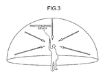
- FIG. 3 is a schematic illustration illustrating the state of use of the photographing device.
- the photographing device 1 is held with a hand and used by the user for photographing surrounding subjects.
- the image pickup devices 103a and 103b illustrated in FIG. 2 capture images of the subjects surrounding the user, so that two respective hemispherical images can be obtained.
- FIG. 4 (a) is a diagram illustrating the hemispherical image (front) taken with the photographing device; (b) is a diagram illustrating the hemispherical image (rear) taken with the photographing device; and (c) is a diagram illustrating an image represented by Mercator projection (hereinafter called "Mercator image").
- the image obtained by the image pickup device 103a is a curved hemispherical image (front) taken through a wide-angle lens 102a to be described later.
- the image obtained by the image pickup device 103b is a curved hemispherical image (rear) taken through a wide-angle lens 102b to be described later.
- the photographing device 1 combines the curved hemispherical image (front) with the hemispherical image (rear) that is inverted therefrom by 180 degrees so as to create the Mercator image as illustrated in FIG. 4(c) .
- FIG. 5 (a) is a diagram illustrating the Mercator image and a portion of the selection image, and (b) is a diagram illustrating the selection image.
- the portion defined by the dashed line in the Mercator image of FIG. 5(a) is used to create the selection image of FIG. 5(b) .
- the selection image is sent from the photographing device 1 illustrated in FIG. 1 to the communication terminal 3a and displayed on the communication terminal 3a. Then, when the user A selects the selection image illustrated in FIG. 5(b) on the communication terminal 3a, the data of the Mercator image illustrated in FIG.
- the Mercator image thus sent is stored in the communication terminal 3a, and, in addition, sent to the image management system 7 via the communication network 9 illustrated in FIG. 1 . Thereafter, the Mercator image is sent from the image management system 7 via the communication network 9 to the communication terminals 3b, 3c, and 3d of the other users, and is stored in the communication terminals 3b, 3c, and 3d.
- the Mercator image can be shared.
- FIG. 6 is a diagram illustrating the full spherical panoramic image.
- the full spherical panoramic image may either be a still image or a moving image.
- a three-dimensional full spherical panoramic image such as illustrated in FIG. 6 is created, for example, by using OpenGL ES that causes the Mercator image illustrated in FIG. 5(a) to be pasted on the surface of a virtual three-dimensional sphere.
- a mere two-dimensional panoramic image may be created instead of the three-dimensional full spherical panoramic image. While the Mercator image is pasted on the virtual three-dimensional sphere here, the Mercator image may, for example, be pasted on a cube, or the two-dimensional panoramic image may be pasted on a circular cylinder.
- FIG. 7 is a diagram illustrating the position of a virtual camera and the position of the predetermined region, assuming the full spherical panoramic image as the surface of the virtual three-dimensional sphere.
- FIG. 8 (a) is a three-dimensional perspective view of FIG. 7, and (b) and (c) are diagrams illustrating the communication terminal displaying, on a display thereof, the predetermined-region images.
- a virtual camera IC illustrated in FIG. 7 is positioned at a point of view of a virtual user viewing the full spherical panoramic image shown on the surface of a three-dimensional sphere CS from inside the three-dimensional sphere CS serving as the full spherical panoramic image.
- the virtual camera IC is specifically positioned in the center of the three-dimensional sphere, and can rotate about three axes (yaw, pitch, and roll) through the center.
- the predetermined region T in the full spherical panoramic image is a portion taken with the virtual camera IC in the full spherical panoramic image, and is specified by predetermined-region information.
- the predetermined-region information is represented by a coordinate x (rH), a coordinate y (rV), and an angle of view ⁇ (angle).
- FIG. 9 is a diagram illustrating a relation between the predetermined-region information and the predetermined-region image.
- a center point CP of 2L provides the (x, y) parameters of the predetermined-region information.
- the distance from the virtual camera IC to the center point CP is denoted as f.
- Equation (1) a trigonometric functional equation generally expressed by Equation (1) is satisfied.
- Zooming of the predetermined region T can be achieved by widening or narrowing the range (arc) of the angle of view ⁇ .
- the image of the predetermined region T in the full spherical panoramic image illustrated in FIG. 8(a) is displayed as the predetermined-region image on a display 315 of the communication terminal 3d, as illustrated in FIG. 8(b) .
- the predetermined-region image in this case is a partial image P 0 representing a part of the full spherical panoramic image.
- the partial image P 0 is an image based on the predetermined-region information that is initially set (by default) in the full spherical panoramic image illustrated in FIG. 6 .
- the predetermined-region image (partial image P 0 )
- Images in certain ranges including the respective attention points AP1, AP2, AP3, and AP4 in the predetermined region T are displayed in the form of thumbnails T1, T2, T3, and T4, respectively, at the bottom of the display 315.
- the display 315 displays a predetermined-region image (here, a partial image P 1 ) in the full spherical panoramic image, as illustrated in FIG. 8(c) , based on the predetermined-region information associated with the thumbnail T1.
- a predetermined-region image here, a partial image P 1
- FIG. 8(c) the thumbnails illustrated in FIG. 8(b) and FIG. 8(c) are images created by the communication terminal 3.
- FIGS. 10 to 12 a description will be made in detail of hardware configurations of the photographing device, the communication terminal, the image processing system, and the image management system in the present embodiment.
- FIG. 10 is a hardware configuration diagram of the photographing device. While the photographing device 1 is assumed to be an omnidirectional photographing device using two image pickup devices in the description below, the photographing device 1 may have three or more, or any number of image pickup devices, and need not be a device dedicated for omnidirectional photographing.
- the photographing device 1 is composed of an image capturing unit 101, an image processing unit 104, an image capturing control unit 105, a central processing unit (CPU) 111, a read-only memory (ROM) 112, a static random access memory (SRAM) 113, a dynamic random access memory (DRAM) 114, the operating unit 115, a network I/F 116, a communication unit 117, and an antenna 117a.
- CPU central processing unit
- ROM read-only memory
- SRAM static random access memory
- DRAM dynamic random access memory
- the image capturing unit 101 is equipped with the wide-angle lenses (what are called fisheye lenses) 102a and 102b each having an angle of view of 180 degrees or more for capturing a hemispherical image, and the two image pickup devices 103a and 103b corresponding to the respective wide-angle lenses.
- the wide-angle lenses what are called fisheye lenses
- the image pickup devices 103a and 103b each contain an image sensor, such as a complementary metal oxide semiconductor (CMOS) sensor or a charge coupled device (CCD) sensor, that converts an optical image formed by the wide-angle lens into image data of electric signals and outputs the image data, a timing generation circuit that generates signals such as horizontal or vertical synchronizing signals and pixel clock signals of the image sensor, and a register group in which various commands, parameters, and the like required for operating the image pickup device are set.
- CMOS complementary metal oxide semiconductor
- CCD charge coupled device
- Both of the image pickup devices 103a and 103b of the image capturing unit 101 are connected to the image processing unit 104 via a parallel I/F bus or a serial I/F bus. Both of the image pickup devices 103a and 103b of the image capturing unit 101 are, in addition, connected to the image capturing control unit 105 via a serial I/F bus (such as an I2C bus).
- the image processing unit 104 and the image capturing control unit 105 are connected to the CPU 111 via a bus 110.
- the bus 110 is also connected with the ROM 112, the SRAM 113, the DRAM 114, the operating unit 115, the network I/F 116, and so on.
- the image processing unit 104 acquires image data output from the image pickup devices 103a and 103b via the parallel I/F bus, and, after applying predetermined processes to the image data, combines the image data to create data of the Mercator image such as illustrated in FIG. 4(c) .
- the image capturing control unit 105 generally serves as a master device and the image pickup devices 103a and 103b serve as slave devices, and the image capturing control unit 105 sets, using the I2C bus, commands and the like in the register groups of the image pickup devices 103a and 103b. The commands and the like as needed are received from the CPU 111.
- the image capturing control unit 105 also uses the I2C bus to acquire status data and the like of each register group of the image pickup devices 103a and 103b, and sends the acquired data to the CPU 111.
- the image capturing control unit 105 instructs the image pickup devices 103a and 103b to output the image data at the time when the shutter button of the operating unit 115 is pressed.
- Some photographing devices have a preview display function and/or a function to display moving images using a display. In those functions, the image data is output from the image pickup devices 103a and 103b continuously at a predetermined frame rate (frames per minute).
- the image capturing control unit 105 also serves, in cooperation with the CPU 111, as a synchronization control unit that synchronizes the output timing of the image data from the image pickup devices 103a and 103b, as will be described later. While the photographing device in the present embodiment is provided with no display unit, a display unit may be provided.
- the CPU 111 controls operation of the entire photographing device 1 and executes necessary processing.
- the ROM 112 stores various computer programs for the CPU 111.
- the SRAM 113 and the DRAM 114 are work memories, which store the programs executed by the CPU 111, data during processing, and the like. Of these two memories, the DRAM 114 stores image data currently being processed by the image processing unit 104 and the data of the Mercator image after being processed.
- the operating unit 115 is a collective term for devices such as various operation buttons, a power switch, the shutter button, and a touch panel having both functions of display and operation input. The user operates the operation buttons so as to enter various photographing modes and photographing conditions.
- the network I/F 116 is a collective term for interface circuits (such as a USB I/F) interfacing with devices such as external media, including an SD card and a USB memory, and a personal computer.
- the network I/F 116 can also be a wireless network interface or a wired network interface.
- the data of the Mercator image stored in the DRAM 114 is recorded into the external medium via the network I/F 116, and/or, as needed, sent to an external device such as the communication terminal 3 via the network I/F 116 that serves as a network I/F.
- the communication unit 117 communicates with the external device such as the communication terminal 3 via the antenna 117a, using the short-range wireless technology such as the Wireless Fidelity (WiFi) or Bluetooth (registered trademark) technology.
- the communication unit 117 can also send the data of the Mercator image to the external device of the communication terminal 3.
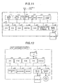
- FIG. 11 is a hardware configuration diagram of a smartphone serving as the communication terminal.
- the communication terminal 3 is equipped with a CPU 301 that controls operation of the entire communication terminal 3; a ROM 302 that stores a basic input/output program; a random access memory (RAM) 303 used as a work area of the CPU 301; an electrically erasable and programmable ROM (EEPROM) 304 that reads and writes data according to the control of the CPU 301; a CMOS 305 as an image pickup device that captures an image of a subject under the control of the CPU 301 to obtain image data; various acceleration/direction sensors 306 including an electromagnetic compass detecting terrestrial magnetism or a gyrocompass, and an acceleration sensor; and a media drive 308 that controls reading and writing (storage) of data from/to a recording medium 307 such as a flash memory. Under the control of the media drive 308, data already recorded in the recording medium 307 is read, or data is newly written into the recording medium 307, which is configured to be removable.
- a recording medium 307 such as a flash memory
- the EEPROM 304 stores an operating system (OS), other computer programs, and various types of data executed by the CPU 301.
- OS operating system
- a CCD may be used instead of the CMOS 305.
- the communication terminal 3 is also equipped with an audio input unit 311 that converts sound into an audio signal; an audio output unit 312 that converts the audio signal into sound; an antenna 313a; a communication unit 313 that uses the antenna 313a to communicate with the nearby base station 9a using wireless communication signals; a global positioning systems (GPS) receiving unit 314 that receives GPS signals including position information (latitude, longitude, and altitude) of the communication terminal 3 from a GPS satellite; the display 315 of liquid crystal or organic EL that displays an image of a subject and various icons; a touch panel 316 that is mounted on the display 315, that is constituted by a pressure-sensitive or electrostatic panel, and that detects a touched position on the display 315 touched by a finger, a touch pen, or the like; and a bus line 310, including an address bus and a data bus, for electrically connecting the above-described units.
- GPS global positioning systems
- the audio input unit 311 includes a microphone for receiving sound
- the audio output unit 312 includes a speaker for producing sound.
- FIG. 12 is a hardware configuration diagram of the image processing system 5 and the image management system 7.
- Both of the image processing system 5 and the image management system 7 are general server computers; therefore, only the configuration of the image processing system 5 will be described below, and description of the configuration of the image management system 7 will be omitted.
- the image processing system 5 is equipped with a CPU 501 that controls operation of the entire image processing system 5; a ROM 502 that stores a computer program, such as an IPL, used for driving the CPU 501; a RAM 503 used as a work area of the CPU 501; an HD 504 that stores various types of data such as computer programs for the image processing system 5; a hard disk drive (HDD) 505 that controls reading and writing of various types of data from/to the HD 504 according to the control of the CPU 501; a media drive 507 that controls reading and writing (storage) of data from/to a recording medium 506 such as a flash memory; a display 508 that displays various types of information such as a cursor, menus, windows, characters, and images; a network I/F 509 for data communication using the communication network 9; a keyboard 511 provided with a plurality of keys for entering characters, numeric values, various instructions, and the like; a mouse 512 used for selecting or executing various instructions, selecting an object to be processed,
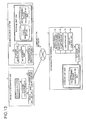
- FIG. 13 is a functional block diagram of the communication terminal 3, the image processing system 5, and the image management system 7 that constitute a part of the image sharing system of the present embodiment.
- the communication terminal 3, the image processing system 5, and the image management system 7 can communicate data via the communication network 9.
- the communication terminal 3 includes a transmission/reception unit 31, an operation input accepting unit 32, a creation unit 33, a display control unit 34, and a storage/extraction unit 39.
- Each of these units is a function or means implemented by operation of any of the constituent elements illustrated in FIG. 11 driven by commands from the CPU 301 according to the programs for the communication terminal 3 that are loaded from the ROM 302 or the EEPROM 304 and deployed in the RAM 303.
- the communication terminal 3 also includes a storage unit 3000 built up with the ROM 302, the RAM 303, and the EEPROM 304 illustrated in FIG. 11 .
- a storage unit 3000 built up with the ROM 302, the RAM 303, and the EEPROM 304 illustrated in FIG. 11 .
- DB predetermined-region management database
- the storage unit 3000 stores therein the data of the photographed image (Mercator image), the selection images, and thumbnails.
- FIG. 14 is a conceptual diagram illustrating the predetermined-region management table.
- the predetermined-region management table manages predetermined-region management information.
- the predetermined-region management information includes thumbnail identification information for identifying a thumbnail, image identification information for identifying a full spherical panoramic image, the predetermined-region information for specifying a predetermined region in the full spherical panoramic image, and a plurality of types of related information related to the predetermined region, in a manner corresponding to each other.
- the thumbnail identification information is, for example, a thumbnail ID for identifying a thumbnail.
- the thumbnail identification information may be, instead of the thumbnail ID, a file name of a thumbnail if the file name can uniquely specify the thumbnail.
- the image identification information is, for example, an image ID for identifying a full spherical panoramic image.
- the image identification information may be, instead of the image ID, another identifier such as a file name if the identifier can uniquely specify the image.
- the related information includes, for example, a "specification date” indicating the date when a user specified the predetermined-region image in the full spherical panoramic image, a "specifying user's name” indicating the user who specified the predetermined-region image, and a "scene” indicating the scene of the predetermined-region image.
- the related information may include, as another example, in addition to the date of specification of the predetermined-region image in the full spherical panoramic image, the time of the specification, the location where the photographed image was taken, and other information.
- the transmission/reception unit 31 of the communication terminal 3 is mainly implemented by processing by the communication unit 313 and the CPU 301 illustrated in FIG. 11 , and sends and receives various types of data (or information) to/from the image processing system 5 and the image management system 7 via the communication network 9.
- the operation input accepting unit 32 is mainly implemented by processing of the touch panel 316 and the CPU 301, and accepts various types of selection and input from the user.
- the creation unit 33 is mainly implemented by processing of the CPU 301. Based on the predetermined-region image in the full spherical panoramic image identified by the image identification information extracted by the storage/extraction unit 39 (the predetermined-region image specified in the predetermined-region information extracted by the storage/extraction unit 39), the creation unit 33 creates a thumbnail for the predetermined-region image, and also creates the thumbnail identification information for identifying the created thumbnail. The creation unit 33 also associates the thumbnail with the thumbnail identification information.
- the creation unit 33 creates a related information selection menu to be described later.
- the creation unit 33 extracts the specifying users' names from the related information, and creates a related information selection menu indicating the specifying users' names such as illustrated in FIG. 29A to be described later.
- the display control unit 34 is mainly implemented by processing of the CPU 301, and controls the display 315 to display various images, characters, and the like. For example, in a full spherical panoramic image identified by the image identification information corresponding to predetermined related information that is selected by the user and accepted by the operation input accepting unit 32, the display control unit 34 controls the display 315 to display the thumbnail for the predetermined-region image that is specified by the predetermined-region information corresponding to the selected and accepted predetermined related information.
- the display control unit 34 also controls the display 315 to display the predetermined-region image corresponding to the thumbnail selected at the operation input accepting unit 32.
- the display control unit 34 further controls the display 315 to display, on the predetermined-region image displayed on the display 315, a related information selection menu (specification date selection menu) 3141 for selecting the date of specification of the predetermined-region image, as illustrated in FIG. 27 to be described later.
- the storage/extraction unit 39 reads data of the specification date selection menu stored in advance in the storage unit 3000, so that the display control unit 34 can control the display 315 to display the specification date selection menu.
- the storage/extraction unit 39 stores various types of data (or information) in the storage unit 3000, and extracts the various types of data (or information) from the storage unit 3000.
- the storage/extraction unit 39 records into and extracts from the storage unit 3000 the data such as the photographed image (Mercator image), the selection images, and the thumbnails.
- the storage/extraction unit 39 searches the predetermined-region management DB 3001 based on the predetermined related information accepted by the operation input accepting unit 32 so as to extract the image identification information and the predetermined-region information corresponding to the predetermined related information.
- the display control unit 34 controls the display 315 to display the thumbnails for the predetermined-region images specified by the predetermined-region information extracted by the storage/extraction unit 39, in the full spherical panoramic image identified by the image identification information extracted by the storage/extraction unit 39.
- the image processing system 5 includes a transmission/reception unit 51, a scene setting unit 52, and a storage/extraction unit 59. Each of these units is a function or means implemented by operation of any of the constituent elements illustrated in FIG. 12 driven by commands from the CPU 501 according to the programs for the image processing system 5 that are loaded from the HD 504 and deployed in the RAM 503.
- the image processing system 5 also includes a storage unit 5000 built up with the RAM 503 and the HD 504 illustrated in FIG. 12 .
- the storage unit 5000 stores therein various types of data (or information).
- the transmission/reception unit 51 of the image processing system 5 is mainly implemented by processing of the network I/F 509 and the CPU 501 illustrated in FIG. 12 , and sends and receives various types of data (or information) to/from the communication terminal 3 and the image management system 7 via the communication network 9.
- the scene setting unit 52 determines which scene of a figure, landscape, structure, and others is represented by the predetermined-region image, and sets an optimal scene for the predetermined-region image. This method for setting a scene is performed based on color information and shape information in the full spherical panoramic image by using a general automatic scene recognition function used in a digital camera.
- the storage/extraction unit 59 stores various types of data (or information) in the storage unit 5000, and extracts the various types of data (or information) from the storage unit 5000.
- the image management system 7 includes a transmission/reception unit 71, a management unit 72, and a storage/extraction unit 79. Each of these units is a function or means implemented by operation of any of the constituent elements illustrated in FIG. 12 driven by commands from the CPU 501 according to the programs for the image management system 7 that are loaded from the HD 504 and deployed in the RAM 503.
- the image management system 7 also includes a storage unit 7000 built up with the RAM 503 and the HD 504 illustrated in FIG. 12 .
- a storage unit 7000 there is established an image management DB 7001 that is composed of an image management table to be described later.
- an image management DB 7002 that is composed of a predetermined-region management table to be described later.
- FIG. 15 is a conceptual diagram illustrating the image management table.
- the image management table manages image management information.
- the image management information includes image identification information for identifying the full spherical panoramic image (photographed image) and auxiliary information serving as metadata of this full spherical panoramic image and the like, in a manner corresponding to each other.
- the image identification information is the same information as the image identification information illustrated in FIG. 14 .
- the auxiliary information includes "disclosure information" indicating whether the user discloses the image in the image sharing system of the present embodiment, a "photographed image data size (MB)", a "shooting date/time of photographed image", and a "number of attention points".
- an "O” mark at the disclosure information indicates that the image is disclosed whereas an "X” mark indicates that the image is not disclosed.
- the number of attention points refers to the number of the attention points set in one full spherical panoramic image as illustrated in FIG. 8B .
- the auxiliary information may include, as another example, in addition to the date/time of shooting of the photographed image, the location where the photographed image was taken and other information.
- FIG. 16 is a conceptual diagram illustrating the predetermined-region management table. Note that the predetermined-region management table illustrated in FIG. 16 is used for managing the photographed images uploaded by the users whereas the predetermined-region management table illustrated in FIG. 14 is used for locally managing the photographed image on the communication terminal 3 individually by the user.
- the transmission/reception unit 71 of the image management system 7 is mainly implemented by processing of the network I/F 509 and the CPU 501 illustrated in FIG. 12 , and sends and receives various types of data (or information) to/from the communication terminal 3 and the image processing system 5 via the communication network 9.
- the management unit 72 adds the image identification information into the header of a photographed image sent from the communication terminal 3 to manage the photographed image in the image management system 7.
- the storage/extraction unit 79 stores various types of data (or information) in the storage unit 7000, and extracts the various types of data (or information) from the storage unit 7000.
- FIG. 17 is a sequence diagram illustrating the process of uploading the photographed image.
- the photographing device 1 combines the two hemispherical images illustrated in FIG. 4(a) and FIG. 4(b) to create the photographed image (Mercator image) illustrated in FIG. 4(c) , and further creates the selection image from the photographed image (Step S1), as illustrated in FIGS. 5 .
- the communication terminal 3a requests the selection image from the photographing device 1 (Step S2). This causes the photographing device 1 to send, to the communication terminal 3a, the selection image created at Step S1 above and the image ID of a photographed image on which the selection image is based (Step S3). As a result, the transmission/reception unit 31 of the communication terminal 3a receives the selection image and the image ID.
- the display control unit 34 of the communication terminal 3a controls the display 315 illustrated in FIG. 11 to display the selection image, and prompts the user A to select the selection image (Step S4).
- the operation input accepting unit 32 accepts the selection (Step S5).
- the transmission/reception unit 31 sends the image ID sent in at Step S3 above back to the photographing device 1, so that the desired photographed image is specified.
- the photographing device 1 accepts the request for the photographed image.
- the photographing device 1 sends, to the communication terminal 3a, the photographed image for which the request is accepted at Step S6 above and the auxiliary information such as the metadata of the photographed image (Step S7).
- the transmission/reception unit 31 of the communication terminal 3a receives the photographed image and the auxiliary information.
- the display control unit 34 of the communication terminal 3a controls the display 315 to display thereon the photographed image (Step S8). This allows the user A to confirm the photographed image to be uploaded to the image management system 7.
- the transmission/reception unit 31 of the communication terminal 3a sends the photographed image to the image management system 7 (Step S9).
- the auxiliary information of the photographed image is also sent with the photographed image.
- the transmission/reception unit 71 of the image management system 7 receives the photographed image and the auxiliary information thereof.
- the management unit 72 of the image management system 7 adds the image identification information into the header of the photographed image (Step S10).
- the image identification information is an ID that is different from the image ID sent and received at Steps S3 and S6 above, and that is added for independently managing the photographed image in the image management system 7.
- the storage/extraction unit 79 stores, in the image management DB 7001, the same image identification information as the image identification information added to the photographed image and the auxiliary information received at Step S9 above, in a manner corresponding to each other as the image management information (Step S11).
- the management unit 72 creates a shared selection image from the photographed image, and adds the same image identification information as the image identification information added at Step S10 above into the header of the data of the shared selection image (Step S12).
- the shared selection image is an image that is selected by the user before the user downloads a desired photographed image from the image management system 7 to specify the photographed image to be downloaded.
- the shared selection image is illustrated in FIG. 19 , and will be further described later.
- the shared selection image is created, for example, using the same method as that of being illustrated at Step S1 above and FIG. 5 .
- the storage/extraction unit 79 stores, in the storage unit 7000 (Step S13), the photographed image to which the image identification information is added at Step S10 above and the shared selection image to which the image identification information is added at Step S11 above.
- the image management information managed in the image management DB 7001 is associated with the photographed image and the shared selection image managed in the storage unit 7000 through the same image identification information.
- FIG. 18 is a sequence diagram illustrating the process of downloading the photographed image and the predetermined-region management information.
- the transmission/reception unit 31 of the communication terminal 3b requests shared selection images and the image management information from the image management system 7 (Step S21). This causes the transmission/reception unit 71 of the image management system 7 to accept the request.
- the storage/extraction unit 79 of the image management system 7 reads data of the shared selection images from the storage unit 7000, and reads the image management information from the image management DB 7001 of the storage unit 7000 (Step S22). Then, the transmission/reception unit 71 sends the shared selection images and the image management information read at Step S22 above to the communication terminal 3b that is the source of the request (Step S23). As a result, the transmission/reception unit 31 of the communication terminal 3b receives the shared selection images and the image management information. Then, the storage/extraction unit 39 of the communication terminal 3b stores the shared selection images and the image management information received at Step S23 above in the storage unit 3000 (Step S24).
- the creation unit 33 of the communication terminal 3b creates a shared image selection list for selection of the photographed image (Step S25).
- the display control unit 34 of the communication terminal 3b controls the display 315 of the communication terminal 3b to display this shared image selection list SL as illustrated in FIG. 19(a) so as to prompt the user B to select a shared selection image CE (Step S26).
- the shared image selection list SL shows the shared selection image CE with the image management information attached thereto. For example, buildings in a commercial area are displayed as the shared selection image CE, and the shooting date/time (2011/1520, 11:21), the photographed image data size (13.1 MB), and the number of attention points set (0) are displayed as the image management information.
- the operation input accepting unit 32 of the communication terminal 3b accepts the selection (Step S27). Then, the transmission/reception unit 31 of the communication terminal 3b sends the image identification information added to the shared selection image CE selected at Step S27 above to the image management system 7 (Step S28). As a result, the transmission/reception unit 71 of the image management system 7 receives the image identification information.
- the storage/extraction unit 79 of the image management system 7 reads, from the storage unit 7000, the photographed image to which the same image identification information as the image identification information received above is added (Step S29). Furthermore, the storage/extraction unit 79 reads, from the predetermined-region management DB 7002 of the storage unit 7000, the predetermined-region management information that includes the same image identification information as the image identification information received above (Step S30). In the image management system 7, based on the "disclosure" attribute in the auxiliary information of the image management information managed by the image management DB 7001, the management unit determines before Step S29 above that the process of Steps S29 and S30 above need not be executed if the attribute indicates nondisclosure (if an "X" mark is given).
- the transmission/reception unit 71 sends, to the communication terminal 3b, the photographed image read at Step S29 above and the predetermined-region management information read at Step S30 above (Step S31).
- the transmission/reception unit 31 of the communication terminal 3b receives the photographed image and the predetermined-region management information, and thus the downloading of the photographed image is terminated. Note that no attention point has yet been set in the photographed image received by the communication terminal 3b, so that the predetermined-region management information contains nothing (is empty).
- the storage/extraction unit 39 of the communication terminal 3b stores the photographed image downloaded at Step S31 above in the storage unit 3000, and also stores the predetermined-region management information downloaded at Step S31 above in the predetermined-region management DB 3001 of the storage unit 1000 (Step S32).
- the creation unit 33 of the communication terminal 3b creates a full spherical panoramic image such as illustrated in FIG. 6 based on the photographed image, and the display control unit 34 controls the display 315 of the communication terminal 3b to display the full spherical panoramic image (Step S33).
- the operation input accepting unit 32 accepts the operation of the user B to cause the display control unit 34 to enlarge and display a part of the full spherical panoramic image as a planar predetermined-region image such as illustrated in FIG. 19(b) .
- the display 315 displays broadly divided areas of a predetermined-region image display area 3110, a thumbnail display area 3120, and a related information selection area 3130.
- the predetermined-region image display area 3110 is an area that displays the full spherical panoramic image or the planar predetermined-region image such as illustrated in FIG. 19(b) .
- the thumbnail display area 3120 is an area that displays thumbnails for the planar predetermined-region images including attention points set by the user.
- the related information selection area 3130 is an area that is used by the user for selection to narrow down the types of the thumbnails, and that displays related information selection buttons to be described later.
- the related information selection area 3130 displays a related information type display button 3130F for displaying the related information selection buttons. When the user selects the related information type display button 3130F, various related information selection buttons to be described later are displayed.
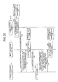
- FIG. 20 is a sequence diagram illustrating the process of setting and registering the predetermined region by the user.
- the communication terminal 3b performs the setting process of the predetermined region including the attention points (Step S41).
- Step S41 will be described more in detail using FIGS. 21 and 22 .
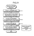
- FIG. 21 is a flowchart illustrating the setting process of the predetermined region.
- FIG. 22 is a screen example illustrating the setting process of the predetermined region.
- the operation input accepting unit 32 accepts the attention point AP1 (Step S41-1).
- the display control unit 34 controls the display 315 to display a selection frame 3113 centered at the attention point AP1 that has been pressed and held (Step S41-2). Note that the perimeter of the selection frame 3113 is masked so as to distinguish the selection frame 3113.
- Step S41-3 the operation input accepting unit 32 accepts the adjustment of the selection frame (Step S41-3).
- This adjustment of the selection frame 3113 changes the coordinates and the angle of view of the virtual camera illustrated in FIG. 7 .
- the operation input accepting unit 32 accepts the setting of the region after being adjusted at Step S41-3 above as an attention region (Step S41-4).
- This communication terminal uses the predetermined-region management information to specify the predetermined region of the photographed image to be managed and to generate a thumbnail.
- This communication terminal also generates thumbnail identification information corresponding to the generated thumbnail, and stores, in the predetermined-region management DB 3001, the thumbnail and the thumbnail identification information in such a manner as to correspond to the predetermined-region management information.
- the image identification information, the predetermined-region information, and the related information except the scene are stored among the types of predetermined-region management information such as illustrated in FIG. 14 .
- the image identification information is the image ID of the photographed image managed in the communication terminal 3.
- the predetermined-region information is the coordinates and the angle of view of the virtual camera that are set at Step S41-4 above.
- the related information is the date/time when the predetermined-region image was specified by setting the predetermined region including the attention point at Step S41-4 above and the name of the user B (who specified the predetermined region) set at Step S41-4 above, and does not include the scene of the attention region.
- An attention point display/nondisplay switching button 3112 is a button for switching between display and nondisplay of the attention point to be described later.
- the transmission/reception unit 31 of the communication terminal 3b sends, to the image processing system 5, the predetermined-region management information and the thumbnail identification information stored at Step S41-5 above (Step S42).
- the transmission/reception unit 51 of the image processing system 5 receives the predetermined-region management information and the thumbnail identification information.
- the image processing system 5 sends the image identification information in the predetermined-region management information received at Step S42 above to the image management system 7 so as to request a photographed image corresponding to the image identification information (Step S43).
- the transmission/reception unit 71 of the image management system 7 receives the image identification information and accepts the request for the photographed image corresponding to the image identification information.
- the storage/extraction unit 79 in the image management system 7 reads, from the storage unit 7000, the photographed image to which the image identification information received at Step S43 above is added (Step S44). Then, the transmission/reception unit 71 sends the photographed image read at Step S44 above to the image processing system 5 (Step S45). As a result, the transmission/reception unit 51 of the image processing system 5 receives the photographed image.
- the scene setting unit 52 in the image processing system 5 sets a scene of the predetermined region set at Step S41-4 above (Step S46). Specifically, based on the photographed image and the predetermined-region information, and based on the information such as colors and lightness of the predetermined-region image in the photographed image, the scene setting unit 52 determines which scene of a figure, landscape, structure, and others is represented by the predetermined region, and sets an optimal scene for the predetermined-region image.
- the communication terminals 3b and 3c receive the information of the already set scene from the image management system 7 when the communication terminals 3b and 3c next access the image management system 7 and execute the process of Steps from S21 to S31 to receive the predetermined-region management information.
- the transmission/reception unit 51 of the image processing system 5 sends, to the image management system 7, the predetermined-region management information including the scene determined at Step S46 above and the thumbnail identification information (Step S47).
- the transmission/reception unit 71 of the image management system 7 receives the predetermined-region management information and the thumbnail identification information.
- the storage/extraction unit 79 of the image management system 7 stores the predetermined-region management information and the thumbnail identification information received at Step S47 above in the predetermined-region management DB 7002 so as to add new pieces of predetermined-region management information and thumbnail identification information (Step S48).
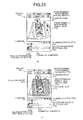
- FIG. 23 a description will be made of a case in which, after the user B illustrated in FIG. 1 sets the attention region, the user C downloads, as illustrated in FIG. 18 , the photographed image, the predetermined-region management information, and the thumbnail identification information from the image management system 7.
- FIG. 23 (a) and (b) are screen examples illustrating the setting process of the predetermined region, and (a) illustrates the screen for the user C corresponds to FIG. 19B illustrating the screen for the user B, and (b) illustrates the screen for the user C corresponds to FIG. 22 illustrating the screen for the user B.
- the attention point AP1 set by the user B is displayed in a certain position in the predetermined-region image (partial image P).
- the thumbnail T1 for the predetermined-region image including the attention point AP1 set by the user B is displayed in the thumbnail display area 3120.
- At the upper right corner in the thumbnail T1 there is displayed the number of comments entered by the users of the image sharing system of the present embodiment who have browsed this predetermined-region image.
- the thumbnail is an image created by the creation unit 33 of the communication terminal 3c of the user C.
- the creation unit 33 creates the thumbnail based on the photographed image and the predetermined-region management information downloaded by the user C at Step S31 above. Specifically, based on the predetermined-region information in the predetermined-region management information received together with the downloaded photographed image, the creation unit 33 determines the coordinates and the angle of view of the virtual camera IC in the full spherical panoramic image based on the photographed image as illustrated in FIG. 7 , and reduces the size of the predetermined-region image in the predetermined region T in this case. Thus, the creation unit 33 creates the thumbnail. The created thumbnail is then associated with the thumbnail identification information that is already received.
- the user C designates the attention point AP2 illustrated in FIG. 23(b) and sets the perimeter of the attention point AP2 as a predetermined-region, so that the same process as that of being illustrated in FIGS. 20 and 21 is executed.
- the various users using the image sharing system set the attention regions, so that the users can know the places attracting attentions of other users. This brings about an effect that the users can quickly browse the places attracting attentions of other users.
- FIG. 24 is a diagram displaying the multiple attention points.
- FIG. 25 is a flowchart illustrating the process of narrowing down the number of the thumbnails.
- the user D displays a predetermined-region image such as illustrated in FIG. 24 on the display 315 of the communication terminal 3d, based on the photographed image and the predetermined-region management information downloaded at Step S31.
- the attention points AP1, AP2, AP3, AP4, and so on are displayed in the predetermined-region image.
- no thumbnail is displayed in the thumbnail display area 3120.
- the operation input accepting unit 32 accepts the pressing (Step S101), as illustrated in FIG. 25 .
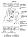
- FIG. 26 is a diagram illustrating the related information type selection buttons.
- the operation input accepting unit 32 accepts the selection of one of the three buttons 3131, 3132, and 3133 (Step S103).
- the operation input accepting unit 32 also determines whether the related information type selection button (Date button) 3131 is accepted (Step S104).
- Step S104 determines that the related information type selection button (Date button) 3131 is pressed “YES”
- the storage/extraction unit 39 reads the data of the specification date selection menu stored in advance in the storage unit 3000 (Step S105). Then, as illustrated in FIG. 27 , the display control unit 34 controls the display 315 to display the related information selection menu (specification date selection menu here) 3141 on the predetermined-region image (Step S106).
- FIG. 27 is a diagram illustrating the specification date selection menu indicating specification dates of predetermined-region images, and is an example of the related information selection menu.
- the operation input accepting unit 32 accepts the selection of the date when the predetermined-region image is specified (Step S107). Then, the storage/extraction unit 39 searches the predetermined-region management DB 3001 using the information of the date accepted at Step S107 as a search key so as to extract predetermined-region management information including the related information whose value of the specification date is the same as the accepted date, and thus narrows down the predetermined-region management information (Step S108).
- the creation unit 33 applies the method illustrated in FIGS. 7 and 8A to specify a predetermined-region image for a photographed image indicated by the image identification information of the predetermined-region management information extracted at Step S108 above, and creates a thumbnail from the predetermined-region image (Step S109).
- the creation unit 33 also creates thumbnails for all pieces of the predetermined-region management information that include the related information whose values of the specification dates are the same as the date accepted at Step S107 above.
- the creation unit 33 associates the created thumbnails with the thumbnail identification information that is already received.
- FIG. 28 is a diagram illustrating the thumbnails.
- Step S104 If Step S104 does not determine that the related information type selection button (Date button) 3131 is pressed “NO”, the storage/extraction unit 39 reads, from the predetermined-region management DB 3001, the related information indicating names related to a button selected out of the related information type selection button (User button) 3132 and the related information type selection button (Scene button) 3133 (Step S111). For example, if Step S103 above accepts the related information type selection button (User button) 3132, all names in the attribute (field) of specifying user's name are read. If Step S103 above accepts the related information type selection button (Scene button) 3133, all names in the attribute (field) of scene are read.
- the creation unit 33 creates a related information selection menu (Step S112). For example, if Step S103 above has selected the related information type selection button (User button) 3132, the creation unit 33 creates a related information selection menu (specifying user's name selection menu) 3142 that indicates names of specifying users who specified the predetermined-region images, as illustrated in FIG. 29(a) . If Step S103 above has selected the related information type selection button (Scene button) 3133, the creation unit 33 creates a related information selection menu (scene selection menu) 3143 that indicates scenes of the predetermined-region images, as illustrated in FIG. 29(b) .
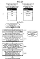
- FIG. 29(a) is a diagram illustrating the specifying user's name selection menu indicating the names of the users specifying the predetermined-region images, and is an example of the related information selection menu.
- FIG. 29(b) is a diagram illustrating the scene selection menu indicating the scenes of the predetermined-region images, and is an example of the related information selection menu.
- Step S113 the display control unit 34 controls the display 315 to display the related information selection menu created at Step S312 above (Step S113). Thereafter, the same process as that of Step S107 above is executed, and thus, description thereof will be omitted.
- FIG. 30 is a flowchart illustrating the process of displaying a predetermined-region image.
- FIG. 34 is a diagram illustrating a predetermined-region image corresponding to a thumbnail.
- Step S201 the operation input accepting unit 32 accepts the selection of the thumbnail.
- the storage/extraction unit 39 searches the predetermined-region management table (refer to FIG. 14 ) to read corresponding predetermined-region information (Step S202).
- the display control unit 34 controls the display 315 to display a predetermined-region image that is obtained by keeping the (x, y) parameters of the predetermined-region information for the predetermined-region image illustrated in FIG. 28 unchanged while gradually changing the angle of view of the virtual camera IC to a predetermined angle of view (Step S203).
- FIG. 31 is a diagram illustrating the predetermined-region image having the predetermined angle of view.
- the angle of view of the predetermined-region image illustrated in FIG. 31 is larger than the angle of view of the predetermined-region image illustrated in FIG. 28 , and thus allows the user to view a wider range.
- the display control unit 34 controls the display 315 to display a predetermined-region image illustrated in FIG. 31 that is obtained by keeping the angle of view of the predetermined-region image illustrated in FIG. 31 unchanged while centering the predetermined-region image at the (x, y) parameters of the predetermined-region information read at Step S202 above (Step S204).
- the display control unit 34 gradually reduces the angle of view of the virtual camera IC while keeping the (x, y) parameters of the predetermined-region information for the predetermined-region image illustrated in FIG. 32 unchanged so as to display a predetermined-region image such as illustrated in FIG. 33 , and further reduces the angle of view to display the predetermined-region image (partial image P 1 ) such as illustrated in FIG. 34 (Step S205).
- FIGS. 32 and 33 are diagrams illustrating the predetermined-region images displayed before the predetermined-region image corresponding to the thumbnail is displayed.
- FIG. 34 is a diagram illustrating the predetermined-region image corresponding to the thumbnail.
- the communication terminal 3 can display the thumbnails for the predetermined-region images in the panoramic image and to accept the selection of a predetermined thumbnail so as to display the predetermined-region image corresponding to the accepted thumbnail in the panoramic image. This brings about an effect that the user can easily find a desired panoramic image or a desired predetermined-region image in the panoramic image.
- the user can narrow down the thumbnails to the desired thumbnail and then specify the predetermined-region image. Therefore, the user can be less confused when browsing the predetermined-region image. This brings about an effect that the user can easily find a desired full spherical panoramic image or a desired predetermined-region image in the full spherical panoramic image.
- FIGS. 35 and 36 a second embodiment of the present invention will be described using FIGS. 35 and 36 . While the image processing system 5 sets the scene in the first embodiment described above, a communication terminal 3' sets the scene in the present embodiment.
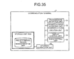
- FIG. 35 is a functional block diagram of the communication terminal according to the present embodiment. While the image processing system 5 includes the scene setting unit 52 in the first embodiment as illustrated in FIG. 13 , the present embodiment differs from the first embodiment in that the communication terminal 3' includes a scene setting unit 35 as illustrated in FIG. 35 .
- Other functional configurations are the same as those of the first embodiment; therefore, the same functions will be given the same signs, and description thereof will be omitted.
- the scene setting unit 35 of the present embodiment is a function or means implemented by operation of any of the constituent elements illustrated in FIG. 10 driven by commands from the CPU 111 according to the programs for the communication terminal 3' that are loaded from the SRAM 113 and deployed in the DRAM 114.
- the scene setting unit 35 sets, based on the data of the photographed image stored in the storage unit 3000 of the communication terminal 3', which scene of a figure, landscape, structure, and others is represented by the photographed image.
- the method for this setting is the same as that of the processing by the scene setting unit 52 in the first embodiment.
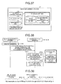
- FIG. 36 is a screen example illustrating a setting process of a predetermined region in the present embodiment.
- the communication terminal 3 does not set the scene of the predetermined-region image, but the image processing system 5 sets the scene of the predetermined-region image as illustrated at Step S46 of FIG. 20 .
- the communication terminal 3' sets the scene of the predetermined-region image between Steps S41-4 and S41-5 of FIG. 21 .
- the display control unit 34 controls the display 315 to display a scene selection menu 3114 for accepting a selection of a scene from the user in the predetermined-region image display area 3110, as illustrated in FIG. 36 .
- the scene selection menu 3114 displays buttons for the user to select any one of the scenes of a figure, landscape, structure, and others.
- the operation input accepting unit 32 recognizes that any one of the buttons is pressed, and the scene setting unit eventually sets a scene.
- the predetermined-region management information including the scene is stored in the predetermined-region management DB 3001 in the present embodiment.
- the predetermined-region management information including the scene is sent from the communication terminal 3' to the image management system 7, directly or via the image processing system 5, so as to be stored by the image management system 7 in the predetermined-region management DB 7002 in the same manner as at Step S48 of FIG. 20 , and to be managed by the image management system 7.
- the predetermined-region management information including the scene is managed in the image sharing system, and thus can be acquired by other users.
- the user can set the scene of the predetermined-region image in the present embodiment. This brings about an effect, in addition to the effects of the first embodiment, that the user can register the predetermined-region image, as a scene intended by the user, in the image sharing system.
- Thumbnails are created in the communication terminal 3 in the first embodiment whereas, in the present embodiment, the thumbnails are created in an image management system 7', which is a feature of the present embodiment.
- FIG. 37 is a functional block diagram of the image management system 7' of the third embodiment. While the communication terminal 3 includes the creation unit 33 in the first embodiment as illustrated in FIG. 13 , the present embodiment differs from the first embodiment in that the image management system 7' includes a creation unit 73 as illustrated in FIG. 37 . Other functional configurations are the same as those of the first embodiment. Therefore, the same functions will be given the same signs, and description thereof will be omitted.
- the creation unit 73 is mainly implemented by processing of the CPU 501 illustrated in FIG. 12 . Based on the predetermined-region image in the full spherical panoramic image identified by the predetermined-region management information (image identification information) read by the storage/extraction unit 39, the creation unit 73 creates a thumbnail for the predetermined-region image, and also creates the thumbnail identification information for identifying the created thumbnail.
- FIG. 38 is a sequence diagram illustrating a process of downloading a photographed image and predetermined-region management information in the third embodiment.
- the same process is executed as that of Steps S21 to S30 of FIG. 18 in the first embodiment; therefore, the process after this process will be described using FIG. 38 .
- the creation unit 73 creates a thumbnail for the predetermined-region image, and also creates the thumbnail identification information for identifying the created thumbnail.
- the transmission/reception unit 71 sends the photographed image read at Step S29 illustrated in FIG. 18 and the predetermined-region management information read at Step S30 illustrated in FIG. 18 to the communication terminal 3b in the same manner as that of Step S31 illustrated in FIG. 18 , and in addition, sends the thumbnail and the thumbnail identification information created at Step S130 illustrated in FIG. 38 (Step S131).
- the transmission/reception unit 31 of the communication terminal 3b receives the photographed image, the thumbnail, the predetermined-region management information, and the thumbnail identification information, and thus the downloading of the photographed image is terminated.
- the thumbnail identification information created at Step S130 above is associated with the image identification information, the predetermined-region information, and the related information of the predetermined-region management information.
- the storage/extraction unit 39 stores the photographed image and the thumbnail downloaded at Step S131 illustrated in FIG. 38 in the storage unit 3000, and stores the predetermined-region management information downloaded at Step S131 above in the predetermined-region management DB 3001 of the storage unit 3000 (Step S132 illustrated in FIG. 38 ).
- the predetermined-region management information stored in the predetermined-region management DB 3001 constitutes a management table having the same form as that of FIG. 16 .
- Step S33 illustrated in FIG. 18 the creation unit 33 of the communication terminal 3b creates a full spherical panoramic image such as illustrated in FIG. 6 based on the photographed image, and the display control unit 34 controls the display 315 of the communication terminal 3b to display the full spherical panoramic image (Step S133 illustrated in FIG. 38 ).
- the image management system 7' can also create the thumbnail in the present embodiment. This brings about an effect, in addition to the effects of the first embodiment, that any program for creating the thumbnail need not be installed on the communication terminals.
- the image processing system 5 and the image management system 7 in the above-described embodiments may be built up with one computer, or may be built up with a plurality of computers arbitrarily assigned with divisions of the units (functions or means).
- the recording medium such as a CD-ROM storing the programs of the above-described embodiments and the HD 504 storing the programs can be provided domestically or internationally as a program product.
- FIG. 39 is a diagram illustrating a description of link information.
- the present invention is not limited to this.
- the display control unit 34 may display all thumbnails with the predetermined-region management information not being narrowed down by the storage/extraction unit 39.
- a communication terminal can display thumbnails for predetermined-region images in a panoramic image and accept a selection of a predetermined thumbnail so as to display the predetermined-region image corresponding to the accepted thumbnail. This brings about an effect that a user can easily find a desired panoramic image or a desired predetermined-region image in the panoramic image.
Landscapes
- Engineering & Computer Science (AREA)
- Theoretical Computer Science (AREA)
- General Engineering & Computer Science (AREA)
- Physics & Mathematics (AREA)
- General Physics & Mathematics (AREA)
- Databases & Information Systems (AREA)
- Data Mining & Analysis (AREA)
- Human Computer Interaction (AREA)
- Signal Processing (AREA)
- Multimedia (AREA)
- Studio Devices (AREA)
- User Interface Of Digital Computer (AREA)
- Processing Or Creating Images (AREA)
- Information Retrieval, Db Structures And Fs Structures Therefor (AREA)
- Two-Way Televisions, Distribution Of Moving Picture Or The Like (AREA)
- Telephone Function (AREA)
- Television Signal Processing For Recording (AREA)
Applications Claiming Priority (2)
| Application Number | Priority Date | Filing Date | Title |
|---|---|---|---|
| JP2012124567 | 2012-05-31 | ||
| JP2013053565A JP6186775B2 (ja) | 2012-05-31 | 2013-03-15 | 通信端末、表示方法、及びプログラム |
Publications (2)
| Publication Number | Publication Date |
|---|---|
| EP2669822A2 true EP2669822A2 (de) | 2013-12-04 |
| EP2669822A3 EP2669822A3 (de) | 2015-06-10 |
Family
ID=48745616
Family Applications (1)
| Application Number | Title | Priority Date | Filing Date |
|---|---|---|---|
| EP13169681.7A Ceased EP2669822A3 (de) | 2012-05-31 | 2013-05-29 | Kommunikationsendgerät, Anzeigeverfahren und Computerprogrammprodukt |
Country Status (4)
| Country | Link |
|---|---|
| US (1) | US9756242B2 (de) |
| EP (1) | EP2669822A3 (de) |
| JP (1) | JP6186775B2 (de) |
| CN (1) | CN103458180B (de) |
Cited By (1)
| Publication number | Priority date | Publication date | Assignee | Title |
|---|---|---|---|---|
| EP3422710A4 (de) * | 2016-03-24 | 2019-04-10 | Samsung Electronics Co., Ltd. | Anzeigevorrichtung und verfahren zur steuerung der anzeigevorrichtung |
Families Citing this family (54)
| Publication number | Priority date | Publication date | Assignee | Title |
|---|---|---|---|---|
| JP6446766B2 (ja) * | 2013-07-08 | 2019-01-09 | 株式会社リコー | プログラム、表示制御装置、記録媒体及び表示制御システム |
| JP6167703B2 (ja) | 2013-07-08 | 2017-07-26 | 株式会社リコー | 表示制御装置、プログラム及び記録媒体 |
| KR20150028066A (ko) * | 2013-09-05 | 2015-03-13 | 엘지전자 주식회사 | 이동 단말기 및 그 제어방법 |
| JP5835383B2 (ja) | 2014-03-18 | 2015-12-24 | 株式会社リコー | 情報処理方法、情報処理装置、およびプログラム |
| JP5835384B2 (ja) | 2014-03-18 | 2015-12-24 | 株式会社リコー | 情報処理方法、情報処理装置、およびプログラム |
| JP6682821B2 (ja) | 2014-12-05 | 2020-04-15 | 株式会社リコー | サービスシステム、情報処理装置、サービス提供方法 |
| US9906720B2 (en) | 2014-12-05 | 2018-02-27 | Ricoh Company, Ltd. | Service system, information processing apparatus, and service providing method |
| JP6358339B2 (ja) * | 2014-12-08 | 2018-07-18 | 株式会社リコー | 画像管理システム、及び画像管理方法 |
| EP3040835B1 (de) | 2014-12-31 | 2021-12-01 | Nokia Technologies Oy | Bildnavigation |
| JP6497965B2 (ja) * | 2015-02-23 | 2019-04-10 | キヤノン株式会社 | 画像処理装置及び画像処理方法 |
| US9924093B1 (en) * | 2015-05-01 | 2018-03-20 | Hoyos Integrity Corporation | Method and apparatus for displaying panoramic images |
| JP6503881B2 (ja) * | 2015-05-20 | 2019-04-24 | 株式会社リコー | コンテンツ提供システム、情報処理装置、プログラム、コンテンツ再生方法 |
| EP3112986B1 (de) * | 2015-07-03 | 2020-02-26 | Nokia Technologies Oy | Inhaltsdurchsuchung |
| JPWO2017014126A1 (ja) * | 2015-07-21 | 2018-06-14 | 株式会社リコー | 画像管理システム、画像管理方法及びプログラム |
| JP6613686B2 (ja) * | 2015-07-29 | 2019-12-04 | 株式会社リコー | 動画表示装置、動画表示方法、およびプログラム |
| JP6633862B2 (ja) * | 2015-08-04 | 2020-01-22 | キヤノン株式会社 | 情報処理装置およびその制御方法 |
| JP2017040687A (ja) * | 2015-08-17 | 2017-02-23 | 株式会社リコー | 画像表示システム、情報処理装置、画像表示方法及びプログラム |
| JP6555026B2 (ja) * | 2015-09-04 | 2019-08-07 | 株式会社リコー | 情報提供システム |
| JP6615545B2 (ja) * | 2015-09-15 | 2019-12-04 | 株式会社トプコン | 画像処理装置、画像処理方法および画像処理用プログラム |
| US9767363B2 (en) | 2015-10-30 | 2017-09-19 | Google Inc. | System and method for automatic detection of spherical video content |
| JP6617547B2 (ja) * | 2015-12-11 | 2019-12-11 | 株式会社リコー | 画像管理システム、画像管理方法、プログラム |
| JP6665558B2 (ja) | 2016-01-29 | 2020-03-13 | 株式会社リコー | 画像管理システム、画像管理方法、画像通信システム及びプログラム |
| KR102111425B1 (ko) | 2016-02-24 | 2020-06-04 | 가부시키가이샤 리코 | 화상 처리 장치, 화상 처리 시스템 및 프로그램 |
| US10652459B2 (en) | 2016-03-07 | 2020-05-12 | Ricoh Company, Ltd. | Information processing system, information processing method, and non-transitory computer-readable storage medium |
| JPWO2017159014A1 (ja) | 2016-03-15 | 2019-01-31 | 株式会社リコー | 画像処理装置、画像処理方法及び画像処理システム |
| US20170309060A1 (en) * | 2016-04-21 | 2017-10-26 | Honeywell International Inc. | Cockpit display for degraded visual environment (dve) using millimeter wave radar (mmwr) |
| CN115118952B (zh) * | 2016-05-13 | 2024-07-19 | 索尼公司 | 信息处理装置和信息处理方法以及再现装置和再现方法 |
| JP6735644B2 (ja) * | 2016-09-20 | 2020-08-05 | キヤノン株式会社 | 情報処理装置及びその制御方法、コンピュータプログラム |
| KR102632795B1 (ko) | 2016-09-21 | 2024-02-02 | 삼성전자주식회사 | 컨텐츠와 연관된 네비게이터 표시 방법 및 이를 구현한 전자 장치 |
| JP6992338B2 (ja) * | 2016-09-30 | 2022-01-13 | 株式会社リコー | 通信システム、通信管理方法、プログラム、システム及び通信方法 |
| JP2018056889A (ja) * | 2016-09-30 | 2018-04-05 | 株式会社リコー | 表示端末、表示方法、及びプログラム |
| CN107993276B (zh) * | 2016-10-25 | 2021-11-23 | 杭州海康威视数字技术股份有限公司 | 一种全景图像的生成方法及装置 |
| US10176615B2 (en) * | 2016-12-13 | 2019-01-08 | Topcon Corporation | Image processing device, image processing method, and image processing program |
| KR102697559B1 (ko) * | 2016-12-22 | 2024-08-23 | 삼성전자주식회사 | 영상 표시 방법, 저장 매체 및 전자 장치 |
| US10417276B2 (en) * | 2017-05-15 | 2019-09-17 | Adobe, Inc. | Thumbnail generation from panoramic images |
| EP3668081A4 (de) * | 2017-08-07 | 2020-07-08 | Sony Corporation | Übertragungsvorrichtung, übertragungsverfahren, empfangsvorrichtung, empfangsverfahren und bildgebungsvorrichtung |
| JP6793615B2 (ja) * | 2017-09-22 | 2020-12-02 | Kddi株式会社 | 表示装置、表示プログラム及び表示システム |
| JP7031228B2 (ja) | 2017-10-26 | 2022-03-08 | 株式会社リコー | プログラム、画像表示方法、画像表示システム、情報処理装置 |
| JP6503098B1 (ja) * | 2018-01-30 | 2019-04-17 | フォージビジョン株式会社 | 画像処理装置、画像処理プログラム及び画像処理方法 |
| JP7081473B2 (ja) | 2018-03-02 | 2022-06-07 | 株式会社リコー | 撮像光学系、撮像システム及び撮像装置 |
| CN110231694A (zh) | 2018-03-05 | 2019-09-13 | 株式会社理光 | 摄像光学系、摄像系统以及摄像装置 |
| WO2019181956A1 (en) | 2018-03-20 | 2019-09-26 | Ricoh Company, Ltd. | Optical system and imaging apparatus |
| JP7124366B2 (ja) | 2018-03-20 | 2022-08-24 | 株式会社リコー | 撮像素子固定構造及び撮像装置 |
| US10852503B2 (en) | 2018-03-20 | 2020-12-01 | Ricoh Company, Ltd. | Joint structure |
| JP2019164303A (ja) | 2018-03-20 | 2019-09-26 | 株式会社リコー | 光学システム及び撮像装置 |
| JP7164831B2 (ja) * | 2018-03-30 | 2022-11-02 | 株式会社リコー | 通信管理システム、通信システム、通信方法、及びプログラム |
| JP7273477B2 (ja) * | 2018-10-02 | 2023-05-15 | パイオニア株式会社 | 表示制御装置、表示制御方法及び表示制御用プログラム |
| JP7268372B2 (ja) * | 2019-01-31 | 2023-05-08 | 株式会社リコー | 撮像装置 |
| JP6679784B2 (ja) * | 2019-03-12 | 2020-04-15 | キヤノン株式会社 | 画像処理装置及び画像処理方法 |
| CN111723271A (zh) * | 2020-07-15 | 2020-09-29 | 山东省计量科学研究院 | 一种度量衡及计量科普知识电子博物馆全息导航展示系统及方法 |
| JP7625808B2 (ja) * | 2020-08-31 | 2025-02-04 | 株式会社リコー | 画像通信システムおよび画像表示方法 |
| JP7700873B2 (ja) * | 2021-11-30 | 2025-07-01 | 日本電信電話株式会社 | 映像処理装置、方法およびプログラム |
| KR20230168859A (ko) * | 2022-06-08 | 2023-12-15 | 현대모비스 주식회사 | 자동차 조명 장치 및 그 작동 방법 |
| CN118015939B (zh) * | 2024-03-13 | 2024-08-16 | 西藏自然科学博物馆 | 一种计量科普知识电子博物馆全息导航展示系统方法 |
Citations (2)
| Publication number | Priority date | Publication date | Assignee | Title |
|---|---|---|---|---|
| US20090160996A1 (en) * | 2005-11-11 | 2009-06-25 | Shigemitsu Yamaoka | Image processing device, image processing method, program thereof, recording medium containing the program, and imaging device |
| JP2011076249A (ja) | 2009-09-29 | 2011-04-14 | Sony Computer Entertainment Inc | パノラマ画像表示装置およびパノラマ画像表示方法 |
Family Cites Families (38)
| Publication number | Priority date | Publication date | Assignee | Title |
|---|---|---|---|---|
| JPH04258825A (ja) | 1991-02-12 | 1992-09-14 | Hitachi Maxell Ltd | 密着貼合わせ型光情報記録媒体 |
| JPH04307483A (ja) | 1991-04-04 | 1992-10-29 | Hokkaido Nippon Denki Software Kk | フロッピィディスク装置障害防止方式 |
| US6396941B1 (en) * | 1996-08-23 | 2002-05-28 | Bacus Research Laboratories, Inc. | Method and apparatus for internet, intranet, and local viewing of virtual microscope slides |
| US6272235B1 (en) * | 1997-03-03 | 2001-08-07 | Bacus Research Laboratories, Inc. | Method and apparatus for creating a virtual microscope slide |
| JPH10336705A (ja) * | 1997-06-02 | 1998-12-18 | Canon Inc | 複眼カメラ |
| IT1312245B1 (it) * | 1998-04-10 | 2002-04-09 | Ricoh Kk | Apparecchiatura, procedimento di elaborazione di immagini e supportodi registrazione leggibile da elaboratore con programma registrato su |
| JP2001186334A (ja) * | 1999-12-27 | 2001-07-06 | Canon Inc | 画像処理装置、画像処理システム、画像処理方法、及び記憶媒体 |
| US20020063725A1 (en) * | 2000-11-30 | 2002-05-30 | Virtuallylisted Llc | Method and apparatus for capturing and presenting panoramic images for websites |
| JP4258825B2 (ja) | 2001-03-01 | 2009-04-30 | 富士フイルム株式会社 | 電子カメラ、画像提供システム及びその方法 |
| JP2003110983A (ja) * | 2001-09-28 | 2003-04-11 | Canon Inc | 撮像装置、画像管理装置、画像管理システム、撮像装置の制御方法、画像管理方法、記録媒体及びプログラム |
| US20100002070A1 (en) * | 2004-04-30 | 2010-01-07 | Grandeye Ltd. | Method and System of Simultaneously Displaying Multiple Views for Video Surveillance |
| JP2005025548A (ja) * | 2003-07-03 | 2005-01-27 | Minolta Co Ltd | 注釈情報付き画像の処理装置、出力方法および出力プログラム |
| JP4837248B2 (ja) * | 2003-10-29 | 2011-12-14 | 京セラ株式会社 | 画像表示装置及び画像表示装置の制御方法 |
| US8427538B2 (en) * | 2004-04-30 | 2013-04-23 | Oncam Grandeye | Multiple view and multiple object processing in wide-angle video camera |
| JP4494196B2 (ja) * | 2004-12-27 | 2010-06-30 | 京セラ株式会社 | 画像表示装置 |
| JP2007018352A (ja) * | 2005-07-08 | 2007-01-25 | Olympus Imaging Corp | 画像表示装置、画像表示プログラム、画像表示方法及び記録媒体 |
| JP4592099B2 (ja) * | 2005-09-29 | 2010-12-01 | キヤノン株式会社 | 画像表示装置及び画像表示方法 |
| US8477154B2 (en) * | 2006-03-20 | 2013-07-02 | Siemens Energy, Inc. | Method and system for interactive virtual inspection of modeled objects |
| WO2007124664A1 (en) * | 2006-04-29 | 2007-11-08 | Shanghai Jietu Software Co., Ltd. | Apparatus and method for collecting panorama graph with location information and method for building, annotating and switching panorama electric map service |
| JP5087867B2 (ja) | 2006-07-04 | 2012-12-05 | ソニー株式会社 | 情報処理装置および方法、並びにプログラム |
| JP4307483B2 (ja) | 2006-12-22 | 2009-08-05 | キヤノン株式会社 | 撮像装置、画像表示装置及びそれらの制御方法、並びに、コンピュータプログラム |
| JP4050777B1 (ja) * | 2007-04-06 | 2008-02-20 | 株式会社デジタルマックス | 画像表示システム |
| US20100122208A1 (en) * | 2007-08-07 | 2010-05-13 | Adam Herr | Panoramic Mapping Display |
| JP5326910B2 (ja) * | 2009-01-20 | 2013-10-30 | ソニー株式会社 | 情報処理装置、情報処理方法およびプログラム |
| JP5338498B2 (ja) | 2009-06-09 | 2013-11-13 | ソニー株式会社 | 監視カメラシステムで使用される制御装置、カメラシステム及びプログラム |
| US9341835B2 (en) * | 2009-07-16 | 2016-05-17 | The Research Foundation Of State University Of New York | Virtual telemicroscope |
| JP5232107B2 (ja) | 2009-09-02 | 2013-07-10 | 株式会社ニコンシステム | 画像表示方法、プログラム、画像表示装置、及び、撮像装置 |
| JP5385059B2 (ja) | 2009-09-07 | 2014-01-08 | 株式会社ニコンシステム | 画像表示方法、プログラム、画像表示装置、及び、撮像装置 |
| US8619098B2 (en) * | 2009-09-18 | 2013-12-31 | Adobe Systems Incorporated | Methods and apparatuses for generating co-salient thumbnails for digital images |
| US8599219B2 (en) * | 2009-09-18 | 2013-12-03 | Adobe Systems Incorporated | Methods and apparatuses for generating thumbnail summaries for image collections |
| KR20110052124A (ko) * | 2009-11-12 | 2011-05-18 | 삼성전자주식회사 | 파노라마 이미지 생성 및 조회 방법과 이를 이용한 휴대 단말기 |
| JP5340895B2 (ja) * | 2009-11-24 | 2013-11-13 | 株式会社ソニー・コンピュータエンタテインメント | 画像データ作成支援装置および画像データ作成支援方法 |
| US20120019614A1 (en) * | 2009-12-11 | 2012-01-26 | Tessera Technologies Ireland Limited | Variable Stereo Base for (3D) Panorama Creation on Handheld Device |
| JP2011211696A (ja) * | 2010-03-10 | 2011-10-20 | Nikon Corp | 画像データ処理システム、画像データ処理プログラム、及び画像データ処理装置 |
| WO2011149558A2 (en) * | 2010-05-28 | 2011-12-01 | Abelow Daniel H | Reality alternate |
| JP5462094B2 (ja) | 2010-07-07 | 2014-04-02 | 株式会社ソニー・コンピュータエンタテインメント | 画像処理装置および画像処理方法 |
| JP5134651B2 (ja) * | 2010-07-07 | 2013-01-30 | 株式会社ソニー・コンピュータエンタテインメント | 画像表示装置および画像表示方法 |
| US20130235084A1 (en) * | 2012-03-12 | 2013-09-12 | Chuan-Wei Wu | Multi-source multiple documents comparison display (presentation or discussion) system |
-
2013
- 2013-03-15 JP JP2013053565A patent/JP6186775B2/ja active Active
- 2013-05-24 US US13/902,124 patent/US9756242B2/en active Active
- 2013-05-29 EP EP13169681.7A patent/EP2669822A3/de not_active Ceased
- 2013-05-30 CN CN201310210163.8A patent/CN103458180B/zh active Active
Patent Citations (2)
| Publication number | Priority date | Publication date | Assignee | Title |
|---|---|---|---|---|
| US20090160996A1 (en) * | 2005-11-11 | 2009-06-25 | Shigemitsu Yamaoka | Image processing device, image processing method, program thereof, recording medium containing the program, and imaging device |
| JP2011076249A (ja) | 2009-09-29 | 2011-04-14 | Sony Computer Entertainment Inc | パノラマ画像表示装置およびパノラマ画像表示方法 |
Cited By (2)
| Publication number | Priority date | Publication date | Assignee | Title |
|---|---|---|---|---|
| EP3422710A4 (de) * | 2016-03-24 | 2019-04-10 | Samsung Electronics Co., Ltd. | Anzeigevorrichtung und verfahren zur steuerung der anzeigevorrichtung |
| US10778966B2 (en) | 2016-03-24 | 2020-09-15 | Samsung Electronics Co., Ltd. | Display device and method for controlling display device |
Also Published As
| Publication number | Publication date |
|---|---|
| US20130326419A1 (en) | 2013-12-05 |
| CN103458180A (zh) | 2013-12-18 |
| JP6186775B2 (ja) | 2017-08-30 |
| US9756242B2 (en) | 2017-09-05 |
| CN103458180B (zh) | 2017-03-01 |
| EP2669822A3 (de) | 2015-06-10 |
| JP2014006880A (ja) | 2014-01-16 |
Similar Documents
| Publication | Publication Date | Title |
|---|---|---|
| US9756242B2 (en) | Communication terminal, display method, and computer program product | |
| US12328527B2 (en) | Image management system, image management method, and computer program product | |
| US11740850B2 (en) | Image management system, image management method, and program | |
| US20140152852A1 (en) | Predetermined-area management system, communication method, and computer program product | |
| JP2014010611A (ja) | 送信装置、画像共有システム、送信方法、及びプログラム | |
| US20180124310A1 (en) | Image management system, image management method and recording medium | |
| CN112825040A (zh) | 用户界面的显示方法、装置、设备及存储介质 | |
| JP5942637B2 (ja) | 付加情報管理システム、画像共有システム、付加情報管理方法、及びプログラム | |
| JP2017182548A (ja) | 画像管理システム、画像管理方法、画像通信システム及びプログラム | |
| JP6233451B2 (ja) | 画像共有システム、通信方法及びプログラム | |
| JP6665440B2 (ja) | 画像管理システム、画像管理方法、画像通信システム及びプログラム | |
| JP2018014141A (ja) | システム、画像共有システム、通信方法、及びプログラム |
Legal Events
| Date | Code | Title | Description |
|---|---|---|---|
| PUAI | Public reference made under article 153(3) epc to a published international application that has entered the european phase |
Free format text: ORIGINAL CODE: 0009012 |
|
| 17P | Request for examination filed |
Effective date: 20130529 |
|
| AK | Designated contracting states |
Kind code of ref document: A2 Designated state(s): AL AT BE BG CH CY CZ DE DK EE ES FI FR GB GR HR HU IE IS IT LI LT LU LV MC MK MT NL NO PL PT RO RS SE SI SK SM TR |
|
| AX | Request for extension of the european patent |
Extension state: BA ME |
|
| PUAL | Search report despatched |
Free format text: ORIGINAL CODE: 0009013 |
|
| AK | Designated contracting states |
Kind code of ref document: A3 Designated state(s): AL AT BE BG CH CY CZ DE DK EE ES FI FR GB GR HR HU IE IS IT LI LT LU LV MC MK MT NL NO PL PT RO RS SE SI SK SM TR |
|
| AX | Request for extension of the european patent |
Extension state: BA ME |
|
| RIC1 | Information provided on ipc code assigned before grant |
Ipc: G06F 17/30 20060101AFI20150505BHEP |
|
| 17Q | First examination report despatched |
Effective date: 20180829 |
|
| STAA | Information on the status of an ep patent application or granted ep patent |
Free format text: STATUS: THE APPLICATION HAS BEEN REFUSED |
|
| 18R | Application refused |
Effective date: 20190710 |