EP2663512B1 - AUSGIEßER UND BEHÄLTNIS MIT EINEM SOLCHEN - Google Patents
AUSGIEßER UND BEHÄLTNIS MIT EINEM SOLCHEN Download PDFInfo
- Publication number
- EP2663512B1 EP2663512B1 EP11805762.9A EP11805762A EP2663512B1 EP 2663512 B1 EP2663512 B1 EP 2663512B1 EP 11805762 A EP11805762 A EP 11805762A EP 2663512 B1 EP2663512 B1 EP 2663512B1
- Authority
- EP
- European Patent Office
- Prior art keywords
- spout
- profile
- lateral
- curvature
- longitudinal
- Prior art date
- Legal status (The legal status is an assumption and is not a legal conclusion. Google has not performed a legal analysis and makes no representation as to the accuracy of the status listed.)
- Active
Links
Images



Classifications
-
- B—PERFORMING OPERATIONS; TRANSPORTING
- B65—CONVEYING; PACKING; STORING; HANDLING THIN OR FILAMENTARY MATERIAL
- B65D—CONTAINERS FOR STORAGE OR TRANSPORT OF ARTICLES OR MATERIALS, e.g. BAGS, BARRELS, BOTTLES, BOXES, CANS, CARTONS, CRATES, DRUMS, JARS, TANKS, HOPPERS, FORWARDING CONTAINERS; ACCESSORIES, CLOSURES, OR FITTINGS THEREFOR; PACKAGING ELEMENTS; PACKAGES
- B65D47/00—Closures with filling and discharging, or with discharging, devices
- B65D47/04—Closures with discharging devices other than pumps
- B65D47/06—Closures with discharging devices other than pumps with pouring spouts or tubes; with discharge nozzles or passages
-
- B—PERFORMING OPERATIONS; TRANSPORTING
- B65—CONVEYING; PACKING; STORING; HANDLING THIN OR FILAMENTARY MATERIAL
- B65D—CONTAINERS FOR STORAGE OR TRANSPORT OF ARTICLES OR MATERIALS, e.g. BAGS, BARRELS, BOTTLES, BOXES, CANS, CARTONS, CRATES, DRUMS, JARS, TANKS, HOPPERS, FORWARDING CONTAINERS; ACCESSORIES, CLOSURES, OR FITTINGS THEREFOR; PACKAGING ELEMENTS; PACKAGES
- B65D75/00—Packages comprising articles or materials partially or wholly enclosed in strips, sheets, blanks, tubes or webs of flexible sheet material, e.g. in folded wrappers
- B65D75/52—Details
- B65D75/58—Opening or contents-removing devices added or incorporated during package manufacture
- B65D75/5861—Spouts
- B65D75/5872—Non-integral spouts
- B65D75/5883—Non-integral spouts connected to the package at the sealed junction of two package walls
-
- B—PERFORMING OPERATIONS; TRANSPORTING
- B29—WORKING OF PLASTICS; WORKING OF SUBSTANCES IN A PLASTIC STATE IN GENERAL
- B29C—SHAPING OR JOINING OF PLASTICS; SHAPING OF MATERIAL IN A PLASTIC STATE, NOT OTHERWISE PROVIDED FOR; AFTER-TREATMENT OF THE SHAPED PRODUCTS, e.g. REPAIRING
- B29C65/00—Joining or sealing of preformed parts, e.g. welding of plastics materials; Apparatus therefor
- B29C65/02—Joining or sealing of preformed parts, e.g. welding of plastics materials; Apparatus therefor by heating, with or without pressure
-
- B—PERFORMING OPERATIONS; TRANSPORTING
- B29—WORKING OF PLASTICS; WORKING OF SUBSTANCES IN A PLASTIC STATE IN GENERAL
- B29C—SHAPING OR JOINING OF PLASTICS; SHAPING OF MATERIAL IN A PLASTIC STATE, NOT OTHERWISE PROVIDED FOR; AFTER-TREATMENT OF THE SHAPED PRODUCTS, e.g. REPAIRING
- B29C66/00—General aspects of processes or apparatus for joining preformed parts
- B29C66/01—General aspects dealing with the joint area or with the area to be joined
- B29C66/05—Particular design of joint configurations
- B29C66/10—Particular design of joint configurations particular design of the joint cross-sections
- B29C66/11—Joint cross-sections comprising a single joint-segment, i.e. one of the parts to be joined comprising a single joint-segment in the joint cross-section
- B29C66/112—Single lapped joints
-
- B—PERFORMING OPERATIONS; TRANSPORTING
- B29—WORKING OF PLASTICS; WORKING OF SUBSTANCES IN A PLASTIC STATE IN GENERAL
- B29C—SHAPING OR JOINING OF PLASTICS; SHAPING OF MATERIAL IN A PLASTIC STATE, NOT OTHERWISE PROVIDED FOR; AFTER-TREATMENT OF THE SHAPED PRODUCTS, e.g. REPAIRING
- B29C66/00—General aspects of processes or apparatus for joining preformed parts
- B29C66/01—General aspects dealing with the joint area or with the area to be joined
- B29C66/05—Particular design of joint configurations
- B29C66/10—Particular design of joint configurations particular design of the joint cross-sections
- B29C66/11—Joint cross-sections comprising a single joint-segment, i.e. one of the parts to be joined comprising a single joint-segment in the joint cross-section
- B29C66/112—Single lapped joints
- B29C66/1122—Single lap to lap joints, i.e. overlap joints
-
- B—PERFORMING OPERATIONS; TRANSPORTING
- B29—WORKING OF PLASTICS; WORKING OF SUBSTANCES IN A PLASTIC STATE IN GENERAL
- B29C—SHAPING OR JOINING OF PLASTICS; SHAPING OF MATERIAL IN A PLASTIC STATE, NOT OTHERWISE PROVIDED FOR; AFTER-TREATMENT OF THE SHAPED PRODUCTS, e.g. REPAIRING
- B29C66/00—General aspects of processes or apparatus for joining preformed parts
- B29C66/01—General aspects dealing with the joint area or with the area to be joined
- B29C66/05—Particular design of joint configurations
- B29C66/10—Particular design of joint configurations particular design of the joint cross-sections
- B29C66/11—Joint cross-sections comprising a single joint-segment, i.e. one of the parts to be joined comprising a single joint-segment in the joint cross-section
- B29C66/114—Single butt joints
-
- B—PERFORMING OPERATIONS; TRANSPORTING
- B29—WORKING OF PLASTICS; WORKING OF SUBSTANCES IN A PLASTIC STATE IN GENERAL
- B29C—SHAPING OR JOINING OF PLASTICS; SHAPING OF MATERIAL IN A PLASTIC STATE, NOT OTHERWISE PROVIDED FOR; AFTER-TREATMENT OF THE SHAPED PRODUCTS, e.g. REPAIRING
- B29C66/00—General aspects of processes or apparatus for joining preformed parts
- B29C66/01—General aspects dealing with the joint area or with the area to be joined
- B29C66/05—Particular design of joint configurations
- B29C66/20—Particular design of joint configurations particular design of the joint lines, e.g. of the weld lines
- B29C66/22—Particular design of joint configurations particular design of the joint lines, e.g. of the weld lines said joint lines being in the form of recurring patterns
- B29C66/221—Particular design of joint configurations particular design of the joint lines, e.g. of the weld lines said joint lines being in the form of recurring patterns being in the form of a sinusoidal wave
-
- B—PERFORMING OPERATIONS; TRANSPORTING
- B29—WORKING OF PLASTICS; WORKING OF SUBSTANCES IN A PLASTIC STATE IN GENERAL
- B29C—SHAPING OR JOINING OF PLASTICS; SHAPING OF MATERIAL IN A PLASTIC STATE, NOT OTHERWISE PROVIDED FOR; AFTER-TREATMENT OF THE SHAPED PRODUCTS, e.g. REPAIRING
- B29C66/00—General aspects of processes or apparatus for joining preformed parts
- B29C66/01—General aspects dealing with the joint area or with the area to be joined
- B29C66/05—Particular design of joint configurations
- B29C66/20—Particular design of joint configurations particular design of the joint lines, e.g. of the weld lines
- B29C66/22—Particular design of joint configurations particular design of the joint lines, e.g. of the weld lines said joint lines being in the form of recurring patterns
- B29C66/223—Particular design of joint configurations particular design of the joint lines, e.g. of the weld lines said joint lines being in the form of recurring patterns being in the form of a triangle wave or of a sawtooth wave, e.g. zigzagged
-
- B—PERFORMING OPERATIONS; TRANSPORTING
- B29—WORKING OF PLASTICS; WORKING OF SUBSTANCES IN A PLASTIC STATE IN GENERAL
- B29C—SHAPING OR JOINING OF PLASTICS; SHAPING OF MATERIAL IN A PLASTIC STATE, NOT OTHERWISE PROVIDED FOR; AFTER-TREATMENT OF THE SHAPED PRODUCTS, e.g. REPAIRING
- B29C66/00—General aspects of processes or apparatus for joining preformed parts
- B29C66/01—General aspects dealing with the joint area or with the area to be joined
- B29C66/05—Particular design of joint configurations
- B29C66/20—Particular design of joint configurations particular design of the joint lines, e.g. of the weld lines
- B29C66/23—Particular design of joint configurations particular design of the joint lines, e.g. of the weld lines said joint lines being multiple and parallel or being in the form of tessellations
- B29C66/232—Particular design of joint configurations particular design of the joint lines, e.g. of the weld lines said joint lines being multiple and parallel or being in the form of tessellations said joint lines being multiple and parallel, i.e. the joint being formed by several parallel joint lines
-
- B—PERFORMING OPERATIONS; TRANSPORTING
- B29—WORKING OF PLASTICS; WORKING OF SUBSTANCES IN A PLASTIC STATE IN GENERAL
- B29C—SHAPING OR JOINING OF PLASTICS; SHAPING OF MATERIAL IN A PLASTIC STATE, NOT OTHERWISE PROVIDED FOR; AFTER-TREATMENT OF THE SHAPED PRODUCTS, e.g. REPAIRING
- B29C66/00—General aspects of processes or apparatus for joining preformed parts
- B29C66/01—General aspects dealing with the joint area or with the area to be joined
- B29C66/05—Particular design of joint configurations
- B29C66/20—Particular design of joint configurations particular design of the joint lines, e.g. of the weld lines
- B29C66/23—Particular design of joint configurations particular design of the joint lines, e.g. of the weld lines said joint lines being multiple and parallel or being in the form of tessellations
- B29C66/234—Particular design of joint configurations particular design of the joint lines, e.g. of the weld lines said joint lines being multiple and parallel or being in the form of tessellations said joint lines being in the form of tessellations
-
- B—PERFORMING OPERATIONS; TRANSPORTING
- B29—WORKING OF PLASTICS; WORKING OF SUBSTANCES IN A PLASTIC STATE IN GENERAL
- B29C—SHAPING OR JOINING OF PLASTICS; SHAPING OF MATERIAL IN A PLASTIC STATE, NOT OTHERWISE PROVIDED FOR; AFTER-TREATMENT OF THE SHAPED PRODUCTS, e.g. REPAIRING
- B29C66/00—General aspects of processes or apparatus for joining preformed parts
- B29C66/01—General aspects dealing with the joint area or with the area to be joined
- B29C66/05—Particular design of joint configurations
- B29C66/302—Particular design of joint configurations the area to be joined comprising melt initiators
- B29C66/3022—Particular design of joint configurations the area to be joined comprising melt initiators said melt initiators being integral with at least one of the parts to be joined
- B29C66/30223—Particular design of joint configurations the area to be joined comprising melt initiators said melt initiators being integral with at least one of the parts to be joined said melt initiators being rib-like
-
- B—PERFORMING OPERATIONS; TRANSPORTING
- B29—WORKING OF PLASTICS; WORKING OF SUBSTANCES IN A PLASTIC STATE IN GENERAL
- B29C—SHAPING OR JOINING OF PLASTICS; SHAPING OF MATERIAL IN A PLASTIC STATE, NOT OTHERWISE PROVIDED FOR; AFTER-TREATMENT OF THE SHAPED PRODUCTS, e.g. REPAIRING
- B29C66/00—General aspects of processes or apparatus for joining preformed parts
- B29C66/50—General aspects of joining tubular articles; General aspects of joining long products, i.e. bars or profiled elements; General aspects of joining single elements to tubular articles, hollow articles or bars; General aspects of joining several hollow-preforms to form hollow or tubular articles
- B29C66/51—Joining tubular articles, profiled elements or bars; Joining single elements to tubular articles, hollow articles or bars; Joining several hollow-preforms to form hollow or tubular articles
- B29C66/53—Joining single elements to tubular articles, hollow articles or bars
- B29C66/532—Joining single elements to the wall of tubular articles, hollow articles or bars
- B29C66/5326—Joining single elements to the wall of tubular articles, hollow articles or bars said single elements being substantially flat
- B29C66/53261—Enclosing tubular articles between substantially flat elements
- B29C66/53262—Enclosing spouts between the walls of bags, e.g. of medical bags
- B29C66/53263—Enclosing spouts between the walls of bags, e.g. of medical bags said spouts comprising wings, e.g. said spouts being of ship-like or canoe-like form to avoid leaks in the corners
-
- B—PERFORMING OPERATIONS; TRANSPORTING
- B29—WORKING OF PLASTICS; WORKING OF SUBSTANCES IN A PLASTIC STATE IN GENERAL
- B29C—SHAPING OR JOINING OF PLASTICS; SHAPING OF MATERIAL IN A PLASTIC STATE, NOT OTHERWISE PROVIDED FOR; AFTER-TREATMENT OF THE SHAPED PRODUCTS, e.g. REPAIRING
- B29C66/00—General aspects of processes or apparatus for joining preformed parts
- B29C66/70—General aspects of processes or apparatus for joining preformed parts characterised by the composition, physical properties or the structure of the material of the parts to be joined; Joining with non-plastics material
- B29C66/73—General aspects of processes or apparatus for joining preformed parts characterised by the composition, physical properties or the structure of the material of the parts to be joined; Joining with non-plastics material characterised by the intensive physical properties of the material of the parts to be joined, by the optical properties of the material of the parts to be joined, by the extensive physical properties of the parts to be joined, by the state of the material of the parts to be joined or by the material of the parts to be joined being a thermoplastic or a thermoset
- B29C66/739—General aspects of processes or apparatus for joining preformed parts characterised by the composition, physical properties or the structure of the material of the parts to be joined; Joining with non-plastics material characterised by the intensive physical properties of the material of the parts to be joined, by the optical properties of the material of the parts to be joined, by the extensive physical properties of the parts to be joined, by the state of the material of the parts to be joined or by the material of the parts to be joined being a thermoplastic or a thermoset characterised by the material of the parts to be joined being a thermoplastic or a thermoset
- B29C66/7392—General aspects of processes or apparatus for joining preformed parts characterised by the composition, physical properties or the structure of the material of the parts to be joined; Joining with non-plastics material characterised by the intensive physical properties of the material of the parts to be joined, by the optical properties of the material of the parts to be joined, by the extensive physical properties of the parts to be joined, by the state of the material of the parts to be joined or by the material of the parts to be joined being a thermoplastic or a thermoset characterised by the material of the parts to be joined being a thermoplastic or a thermoset characterised by the material of at least one of the parts being a thermoplastic
-
- B—PERFORMING OPERATIONS; TRANSPORTING
- B29—WORKING OF PLASTICS; WORKING OF SUBSTANCES IN A PLASTIC STATE IN GENERAL
- B29L—INDEXING SCHEME ASSOCIATED WITH SUBCLASS B29C, RELATING TO PARTICULAR ARTICLES
- B29L2031/00—Other particular articles
- B29L2031/712—Containers; Packaging elements or accessories, Packages
- B29L2031/7128—Bags, sacks, sachets
Definitions
- the present invention relates to a spout according to the preamble of claim 1, as it is known from US 2009/285510 is known; in particular, a welding spout with a channel forming a channel for filling or emptying a plastic bag plastic body having side surfaces which are at least partially away from each other, provided with a surface structure and merge into two sides, wherein the side surfaces formed for connection to a plastic film are. Furthermore, the invention relates to a container comprising a foil bag and such a spout.
- the surface structure has a profile with a height of 0.1 mm to 0.5 mm above a base surface of the side surface. Due to the use of such a surface structure, parts of the foil welded to the side face are increasingly in a position which is angled with respect to the main pulling direction after a welding process, which brings about an improvement in the carrying capacity, in particular in the case of rounded or other blurred edges.
- a main draw direction is usually a direction parallel to a longitudinal central axis of the channel.
- the base area is determined by an area which, viewed in each case perpendicular to the side surface, leads through the lowest area (s) of the side area and otherwise runs parallel to structureless areas of the side area.
- the base surface With a smooth side surface, the base surface would be defined by the side surface itself and there would be no raised profile.
- height is meant the distance of a surface leading through the highest point of the profile and running parallel to the base surface. It is therefore the maximum height of the profile, which is formed, for example, in a sectional wave-shaped profile through the highest point on the wave crest. Large parts of the surface structure can thus also have a lower height.
- the profile in a cut to half the maximum height of the profile between 30% and 60% of the surface structure in the section.
- the profile thus has mountains and valleys / spaces.
- At least 10% of the surface area of the side surface has a structure according to the invention, so that the shearing forces required for tearing off the welding spout from the film bag have already increased significantly.
- a projection is understood to mean a projection along a vertical on the base surface.
- the surface structures are in particular rounded, viewed transversely to a longitudinal extent, and may in particular be web-like structures.
- the height of the profile is between 0.1 mm and 0.3 mm, more preferably between 0.12 mm and 0.2 mm. These heights are typical of the film thicknesses used 0.05 mm to 0.5 mm is particularly advantageous, since in the welding tests carried out an optimum concerning the tensile strength has resulted.
- the profile thus has regions facing away from an underside of the spout, which is typically a surface formed transverse to the longitudinal axis of the channel. Tabs or overhangs with respect to the bottom.
- a uniform introduction of the force into the spout is effected in particular by at least one longitudinal back and / or longitudinal groove formed profile. It begins or ends such a longitudinal ridge or a longitudinal groove in each case in the region of a lateral lug, wherein under flag a non-hollow side portion, which is formed by the laterally merging side surfaces, is meant.
- a transverse extent along an underside from one to the other side of a spout the formation of vertical air inclusions or vertically extending channels is effectively prevented in addition to a defined introduction of force.
- the container according to the invention is thus additionally sealed.
- the longitudinal ridges or longitudinal grooves extend wavy from one lug to the other lug, wherein the deflection regions still have a radius of curvature which at least corresponds to the film thickness.
- the radius of curvature is at least more than 0.05 mm in order not to form a tip pointing in the opposite direction to one of the main load direction of the compound film spout, which can damage the film structure in the event of loading.
- a further protection against the formation of leaks is achieved by an inventive design of a spout, which has a profile section, viewed in the longitudinal direction at least partially adjacent to a further profile section, viewed in the transverse direction and along the side surface this partially overlapped or covers.
- Transverse direction here means a direction transverse, i. in particular vertical to a longitudinal central axis of the channel, longitudinal direction a direction along a longitudinal axis of the channel.
- the side surfaces may have profiles provided with spiral or L- or C-shaped adjacent sections.
- An inventive spout is further provided with a plurality of juxtaposed longitudinal ridges or longitudinal grooves which run at the above defined height across the entire side surface and all start on one side in the region of a flag and end on the other side.
- waves ie, for example, sinusoidal shaped profile backs, which lie close to each other and in a direction parallel to a longitudinal central axis of the channel no sharp edges but smooth and soft transitions form, the tightness and carrying capacity of the compound of a spout invention a foil bag according to the invention increases.
- the profiles may run off in the area of the flag, i. also have heights of less than 0.1 mm.
- these can also surround a plurality of depressions into which a film of a film bag is pressed or pulled in a fastening operation.
- a lower outer edge of the plastic body in particular of the shuttle, a Represent a vulnerability in the sense of a target tear line. It is therefore advantageous to provide this edge with a smaller curvature on average than an upper outer edge of the plastic body.
- the lower outer edge of the shuttle may have a smaller curvature than a lower inner edge of the shuttle, in which case the edges of the sidewalls forming the shuttle are meant.
- the curvature of the lower outer edge of the side wall of the shuttle increases toward the sides, eg in the direction of any flags.
- the curvature of the upper edge corresponds to that of an edge commonly used in spouts.
- the matching of the surface structure to the foil to be attached to the spout is facilitated if the radius of curvature of one or the lower outer edge at least corresponds to the height of the profile.
- the profile and edge can then have similar curvatures which do not damage the integrity of the film bag material of a film bag to be attached to the spout.
- the profile may be partially reduced in height, but will not necessarily disappear completely, so that even with a welding on the foil bag still a certain structuring in the Weld seam is visible. Due to the resulting deflection of the film, the load-bearing capacity of the compound is improved when the film is intact.
- An inventive spout which is designed as a welding spout, shows after Fig. 2 a side surface 1, which has a profile formed by a total of six wavy lines 2.
- the wavy lines 2 are located as longitudinal ridges raised on a surface 3, which forms the base surface of the side surface 1.
- the height of the middle crests of the longitudinal ridges over the base area is 0.15 mm.
- the longitudinal ridges begin and end each in the area of lateral lugs 4, which at the same time a transition region between the in Fig. 1 form the side surface shown and the rear side surface, not shown.
- the left side in the figure represents a side A, while the right side in the figure is designated B.
- a light edge 6, viewed in the direction of the axis 5, indicates the beginning of a curvature of the lower outer edge 7 of the side surface. This runs to the flags 4 and thus to the sides A, B of the side surfaces.
- the bag is particularly safe and dense.
- the undulating longitudinal ridges 2 project over more than 10% of the base surface (3) projected onto the base surface (3).
- about 30% of the base area is covered by the surface structure.
- melting tips 13 of the wavy longitudinal backs at least partially flow into the located between the longitudinal back valleys 14, the bottom of which is formed by the base surface. If the valleys 14 were to be made narrower, longitudinal ridges on the boat could increasingly be formed and, at an average height of (maximum) height, more than 30% of the structure would lie.
- the longitudinal backs 2 also have a plurality of deflections and leak in the area of the flags.
- Fig. 6 also shows rimmed areas Especially the surface structures of the embodiments of the Fig. 1 and 5 are well suited for spouts, which have 12 formed by webs guide grooves. Due to the improved load-bearing capacity of the connection of pouring spout and foil bag, the containers, which have been held over the webs, can be transported faster as well as filled faster and with larger quantities as well as altogether more safely.
Landscapes
- Engineering & Computer Science (AREA)
- Mechanical Engineering (AREA)
- Bag Frames (AREA)
Description
- Die vorliegende Erfindung betrifft einen Ausgießer gemäß dem Oberbegriff des Anspruchs 1, wie er aus der
US 2009/285510 bekannt ist; insbesondere einen Einschweiß-Ausgießer mit einem einen Kanal zum Befüllen oder Entleeren eines Kunststoffbeutels ausbildenden Kunststoffkörper, der Seitenflächen aufweist, die zumindest bereichsweise voneinander weg weisen, mit einer Oberflächenstruktur versehen sind und an zwei Seiten ineinander übergehen, wobei die Seitenflächen zur Verbindung mit einer Kunststofffolie ausgebildet sind. Des Weiteren betrifft die Erfindung ein Behältnis umfassend einen Folienbeutel und einen solchen Ausgießer. - Aus dem Stand der Technik ist es bekannt, die Seitenflächen eines auch Schiffchen genannten Teils eines Einschweiß-Ausgießers mit einem Folienbeutel zu verschweißen. Zur optimalen Verbindung zwischen Ausgießer und Folienbeutel wurden die Seitenflächen des Schiffchen des Ausgießers im Stand der Technik mit einer Oberflächenstruktur einer bestimmten Rauigkeit versehen (
EP 1 701 892 B1 ). Nachteilig bei dieser Art der Oberflächenstruktur der Seitenflächen des Schiffchens ist jedoch die mögliche Ausbildung von in Längsrichtung des Kanals verlaufenden Lufteinschlüssen oder Hohlkanälen, die zu Undichtigkeiten eines einen Folienbeutel und einen mit diesem verschweißten Ausgießer aufweisenden Beutels führen können. Darüber hinaus hat es sich gezeigt, dass beim Befüllen von größeren Beuteln die Verbindung zwischen Oberfläche und Folienbeutel durch zu starke Scherkräfte beschädigt werden kann. - Es ist daher Aufgabe der vorliegenden Erfindung, einen Ausgießer für ein Behältnis sowie ein zugehöriges Behältnis hinsichtlich seiner Tragfähigkeit sowie seiner Dichtigkeit verbessert auszubilden.
- Die Aufgabe wird gelöst durch einen Gegenstand nach Anspruch 1 sowie durch einen Gegenstand gemäß Anspruch 9. Vorteilhafte Ausgestaltungen der Erfindung sind den auf diese Ansprüche rückbezogenen Unteransprüchen sowie der nachfolgenden Beschreibung zu entnehmen.
- Erfindungsgemäß ist vorgesehen, dass die Oberflächenstruktur ein Profil mit einer Höhe von 0,1 mm bis 0,5 mm über einer Basisfläche der Seitenfläche aufweist. Durch die Verwendung einer solchen Oberflächenstruktur befinden sich nach einem Einschweißvorgang vermehrt Teile der mit der Seitenfläche verschweißten Folie in einer gegenüber der Hauptzugrichtung abgewinkelten Lage, was insbesondere bei gerundeten oder anderen unscharfe Kanten aufweisenden Oberflächenstrukturen eine Verbesserung der Tragfähigkeit bewirkt. Eine Hauptzugrichtung ist in der Regel eine Richtung parallel zu einer Längsmittelachse des Kanals. Die Basisfläche wird hierbei durch eine Fläche bestimmt, die -betrachtet jeweils lotrecht auf der Seitenfläche- durch den oder die tiefsten Bereiche/Punkte der Seitenfläche führt und ansonsten parallel zu strukturlosen Bereichen der Seitenfläche läuft. Bei einer glatten Seitenfläche würde die Basisfläche durch die Seitenfläche selbst definiert sein und es läge keine erhöhtes Profil vor. Unter Höhe ist hierbei der Abstand einer durch den höchsten Punkt des Profils führenden und parallel zur Basisfläche verlaufenden Fläche zu verstehen. Es handelt sich somit um die maximale Höhe des Profils, welches beispielsweise bei einem im Schnitt wellenförmigen Profil durch den höchsten Punkt auf dem Wellenkamm ausgebildet wird. Weite Teile der Oberflächenstruktur können somit auch eine niedrigere Höhe aufweisen.
- Vorteilhafterweise liegen bei einem Schnitt auf der Hälfte der maximalen Höhe des Profils zwischen 30 % und 60 % der Oberflächenstruktur im Schnitt. Das Profil weist somit Berge und Täler/Zwischenräume auf. Bei einem solchen Wert kann die bei einem Einschweiß-Vorgang in die Spitzen des Profils eingeleitete Wärme einerseits gut weitergeleitet werden und kann andererseits zur Verflüssigung der maximal hohen Bereiche des Profils führen, die dann in die Zwischenräume fließen können. Auch hierdurch wird wiederum eine festere Verbindung erzielt, da der verflüssigte Kunststoff eine gute Verbindung mit der anzuschweißenden Folie und dem Kunststoffkörper herstellt.
- Vorteilhafterweise weisen zumindest 10% der Oberfläche der Seitenfläche eine erfindungsgemäße Struktur auf, so dass die zum Abreißen des Einschweiß-Ausgießers von dem Folienbeutel benötigten Scherkräfte bereits signifikant gestiegen sind. Demnach sind projiziert auf die Basisfläche mehr als 10 % der Basisfläche von der Oberflächenstruktur bedeckt. Unter eine Projektion wird hierbei eine Projektion entlang einer Vertikalen auf der Basisfläche verstanden. Die Oberflächenstrukturen sind insbesondere quer zu einer Längserstreckung betrachtet gerundet, es kann sich insbesondere um stegartige Strukturen handeln. Vorteilhafterweise liegt die Höhe des Profils zwischen 0,1 mm und 0,3 mm, besonders bevorzugt zwischen 0,12 mm und 0,2 mm. Diese Höhen sind bei den typischerweise verwendeten Folienstärken von 0,05 mm bis 0,5 mm besonders vorteilhaft, da sich bei den durchgeführten Einschweißversuchen hierbei ein Optimum betreffend die Reißfestigkeit ergeben hat.
- Vorzugsweise weist das Profil somit von einer Unterseite des Ausgießers, die in der Regel eine quer zur Längsachse des Kanals ausgebildete Fläche darstellt, abgewandte Bereiche auf, d.h. Vorsprünge oder Überhänge bezüglich der Unterseite.
- Eine gleichmäßige Einleitung der Kraft in den Ausgießer wird insbesondere durch zumindest einen Längsrücken und/oder Längsfurche ausgebildetes Profil bewirkt. Es beginnt oder endet ein solcher Längsrücken oder eine Längsfurche jeweils im Bereich einer seitlichen Fahne, wobei unter Fahne ein nicht hohler Seitenabschnitt, der durch die seitlich ineinander übergehenden Seitenflächen gebildet wird, gemeint ist. Durch eine solche Quererstreckung entlang einer Unterseite von einer zur anderen Seite eines Ausgießers wird neben einer definierten Krafteinleitung auch die Ausbildung von vertikal verlaufenden Lufteinschlüssen oder vertikal verlaufenen Kanälen wirkungsvoll verhindert. Das erfindungsgemäße Behältnis ist somit zusätzlich abgedichtet.
- Es hat sich darüber gezeigt, dass bei einer Ausbildung von Längsrücken und/oder Längsfurchen aufweisenden Profilen entlang der Seitenfläche, die mehrfach umgelenkt werden, d.h. die beispielsweise von einer Links- in eine Rechts- und wieder in eine Linkskurve übergehenden Profile aufweisen, gezeigt, dass die Ausbildung von zu Undichtigkeiten führenden Lufteinschlüssen zusätzlich wirkungsvoll behindert wird. Dies gilt insbesondere für von einer Seite, z.B. einer linken Fahne zu einer rechten Fahne verlaufende Längsrücken- oder -furchen. Durch die Mehrfach-Umlenkung können selbst teilweise gebogene Lufteinschlüsse nicht zu Undichtigkeiten führen.
- Erfindungsgemäß verlaufen die Längsrücken oder Längsfurchen wellenförmig von einer Fahne zur anderen Fahne, wobei die Umlenkungsbereiche immer noch einen Krümmungsradius aufweisen, der zumindest der Folienstärke entspricht. Der Krümmungsradius beträgt zumindest mehr als 0,05 mm, um keine zu einer der Hauptbelastungsrichtung der Verbindung Folie-Ausgießer entgegengesetzten Richtung weisende Spitze auszubilden, die im Belastungsfall die Folienstruktur beschädigen kann.
- Eine weitere Absicherung gegen die Ausbildung von Undichtigkeiten wird durch eine erfindungsgemäße Ausbildung eines Ausgießers erreicht, der einen Profilabschnitt aufweist, der in Längsrichtung betrachtet zumindest teilweise zu einem weiteren Profilabschnitt benachbart ist, in Querrichtung und längs der Seitenfläche betrachtet diesen teilweise überlappt oder abdeckt. Querrichtung meint hierbei eine Richtung quer, d.h. insbesondere vertikal zu einer Längsmittelachse des Kanals, Längsrichtung eine Richtung längs zu einer Längsachse des Kanals.
- So können die Seitenflächen beispielsweise mit spiralförmigen oder L- oder C-förmigen nebeneinanderliegenden Abschnitten versehene Profile aufweisen. Ein erfindungsgemäßer Ausgießer ist weiterhin mit einer Mehrzahl von nebeneinander angeordneten Längsrücken oder Längsfurchen versehen, die bei der vorstehend definierten Höhe quer über die gesamte Seitenfläche laufen und alle auf einer Seite im Bereich einer Fahne beginnen und auf der anderen Seite enden. Durch die Verwendung von Wellen, d.h. beispielsweise sinusförmig ausgebildeten Profilrücken, die dicht an dicht liegen und auch in einer Richtung parallel zu einer Längsmittelachse des Kanals keine scharfen Kanten sondern sanfte und weiche Übergange ausbilden, wird die Dichtigkeit und die Tragkraft der Verbindung eines erfindungsgemäßen Ausgießers mit einem Folienbeutel erfindungsgemäß erhöht.
- Um eine gute Integration in den Seitenbereichen, d.h. insbesondere im Bereich der Fahne zu bewirken, können die Profile im Bereich der Fahnen auslaufen, d.h. auch Höhen von weniger als 0,1 mm aufweisen.
- Ergänzend zu einer Mehrzahl von Wellen können diese auch eine Mehrzahl von Vertiefungen umranden, in die eine Folie eines Folienbeutels in einem Befestigungsvorgang eingepresst oder gezogen wird.
- Durch die Erhöhung der Tragkraft eines erfindungsgemäßen Behältnisses kann eine untere äußere Kante des Kunststoffkörpers, insbesondere des Schiffchens, eine Schwachstelle in Sinne einer Soll-Reißlinie darstellen. Es ist daher vorteilhaft, diese Kante mit einer im Mittel kleineren Krümmung zu versehen als eine obere äußere Kante des Kunststoffkörpers. Alternativ oder ergänzend kann die untere äußere Kante des Schiffchens eine geringere Krümmung aufweisen als eine untere innere Kante des Schiffchens, wobei hierbei die Kanten der das Schiffchen ausbildenden Seitewände gemeint sind. Vorzugsweise nimmt die Krümmung der unteren äußeren Kante der Seitenwand des Schiffchens zu den Seiten z.B. in Richtung etwaiger Fahnen hin zu. Die Krümmung der oberen Kante entspricht der einer üblicherweise bei Ausgießern verwendeten Kante.
- Die Abstimmung der Oberflächenstruktur auf die an dem Ausgießer zu befestigende Folie ist erleichtert, wenn der Krümmungsradius einer oder der unteren äußeren Kante zumindest der Höhe des Profils entspricht. Profil und Kante können dann ähnliche Krümmungen aufweisen, die die Integrität des Folienbeutelmaterials eines an dem Ausgießer zu befestigenden Folienbeutels nicht beschädigen.
- Die vor- und nachbeschriebenen Vorteile können auch einem erfindungsgemäßen Behältnis zukommen, welches einen Folienbeutel umfassend einen mit diesem verbundenen Ausgießer aufweist, wobei der Ausgießer wie vor- oder nachbeschrieben ausgebildet ist.
- Durch einen Verschweißvorgang kann sich das Profil in der Höhe teilweise reduzieren, wird jedoch nicht notwendigerweise komplett verschwinden, so dass auch bei einem Verschweißen am Folienbeutel noch eine gewisse Strukturierung im Bereich der Schweißnaht zu erkennen ist. Durch die sich hierdurch ergebende Umlenkung der Folie ist die Belastbarkeit der Verbindung bei intakter Folie verbessert.
- Weitere Vorteile und Einzelheiten der Erfindung lassen sich der nachfolgenden Figurenbeschreibung entnehmen. In den schematischen Darstellungen der Figuren zeigt:
- Fig. 1
- einen erfindungsgemäßen Gegenstand in einer Seitenansicht,
- Fig. 2
- den Gegenstand nach
Fig. 1 in einer Draufsicht, - Fig. 3
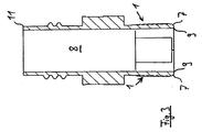
- den Gegenstand nach
Fig. 2 entlang des Schnitts III-III, - Fig. 4
- einen Ausschnitt des linken unteren Teils des Gegenstands nach
Fig. 3 , - Fig. 5
- einen weiteren Gegenstand aus dem Stand der Technick,
- Fig. 6
- einen weiteren Gegenstand aus dem Stand der Technick.
- Gleich oder ähnlich wirkende Teile sind - sofern dienlich - mit identischen Bezugsziffern versehen. Einzelne technische Merkmale der nachfolgend beschriebenen Ausführungsbeispiele können auch mit den Merkmalen der vorbeschriebenen Ausführungsbeispiele zu erfindungsgemäßen Weiterbildungen führen.
- Ein erfindungsgemäßer Ausgießer, der als Einschweiß-Ausgießer ausgebildet ist, weist nach
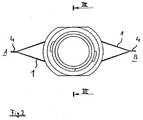
Fig. 2 eine Seitenfläche 1 auf, die ein durch insgesamt sechs Wellenlinien 2 gebildetes Profil aufweist. Die Wellenlinien 2 befinden sich als Längsrücken erhaben auf einer Oberfläche 3, die die Basisfläche der Seitenfläche 1 ausbildet. Die Höhe der Mittelkämme der Längsrücken über der Basisfläche beträgt 0,15 mm. Die Längsrücken beginnen und enden jeweils im Bereich seitlicher Fahnen 4, die gleichzeitig einen Übergangsbereich zwischen der in derFig. 1 gezeigten Seitenfläche und der nicht dargestellten rückseitigen Seitenfläche ausbilden. Die in der Figur linke Seite stellt eine Seite A dar, während die in der Figur rechte Seite mit B bezeichnet wird. - Durch die mehrfache Umlenkung der annähernd sinusförmigen Längsrücken und deren Quererstreckung von Seite A zu Seit B wird die Ausbildung von in Richtung einer Längsmittelachse 5 eines Kanals verlaufenden Lufteinschlüssen wirkungsvoll verhindert.
- Eine Lichtkante 6 zeigt in Richtung der Achse 5 betrachtet den Beginn einer Krümmung der unteren äußeren Kante 7 der Seitenfläche an. Diese läuft zu den Fahnen 4 und mithin zu den Seiten A, B der Seitenflächen aus.
- In der Draufsicht nach der
Fig. 2 ersichtlich sind die Seitenflächen 1 voneinander weggerichtet und symmetrisch aufgebaut. - Sowohl in Längsrichtung L als auch in Querrichtung Q, d.h. vertikal zur Längsmittelachse 5 betrachtet, überschneiden bzw. überlappen sich entlang der Basisfläche 3 betrachtet die einzelnen Längsrücken. Durch die geschwungene Ausbildung können sowohl Kräfte in Richtung der vertikalen Längsmittelachse wie auch quer dazu gut abgefangen werden. Der Beutel ist besonders sicher und dicht ausgebildet.
- Aus
Fig. 3 ersichtlich sind beide Kanten 7 unter außen an den Seitenflächen 1 weniger scharf ausgebildet als die einen inneren Kanal 8, durch den ein Folienbeutel befüllt oder entleert werden kann, begrenzenden Kanten 9 (vgl. auchFig. 4 ). Entsprechendes gilt für die obere äußere Kante 11 des Kunststoffkörpers. Darüber hinaus zeigtFig. 4 die Definition der Höhe H eines insbesondere gerundet ausgebildeten Längsrückens über der Basisfläche 3. - Die wellenförmigen Längsrücken 2 bedecken projiziert auf die Basisfläche (3) mehr als 10 % der Basisfläche (3). In der
Fig. 4 sind im vorliegenden Fall rund 30 % der Basisfläche durch die Oberflächenstruktur bedeckt. So können bei einem Einschweiß-Vorgang abschmelzende Spitzen 13 der wellenförmigen Längsrücken zumindest teilweise in die zwischen den Längsrücken befindlichen Täler 14 fließen, deren Grund von der Basisfläche ausgebildet wird. Sofern die Täler 14 schmaler ausgebildet werden würden, könnten vermehrt Längsrücken auf dem Schiffchen ausgebildet werden und im Schnitt auf halber Höhe der (maximalen) Höhe würden mehr als 30 % der Struktur liegen. - In den
Fig. 5 und6 sind weitere Ausführungsbeispiele aus dem Stand der Technick gezeigt, deren Längsrücken 2 ebenfalls eine Vielzahl von Umlenkungen aufweisen und die im Bereich der Fahnen auslaufen.Fig. 6 zeigt darüber hinaus umrandete Bereiche Besonders die Oberflächenstrukturen der Ausführungsbeispiele nach denFig. 1 und5 sind gut geeignet für Ausgießer, die durch Stege 12 ausgebildete Führungsnuten aufweisen. Durch die verbesserte Tragfähigkeit der Verbindung von Ausgießer und Folienbeutel können die über die Stege gehaltenen, bereits befüllten Behältnisse sowohl schneller transportiert als auch schneller und mit größeren Mengen sowie insgesamt sicherer befüllt werden.
Claims (10)
- Ausgießer, insbesondere Einschweiß-Ausgleßer, mit einem einen Kanal (8) zum Befüllen oder Entleeren eines Kunststoffbeutels ausbildenden Kunststoffkörper (10), der Seitenflächen (1) aufweist, die zumindest bereichsweise voneinander weg weisen und an zwei Seiten (A,B) in einer seitlichen Fahne (4) ineinander übergehen, wobei die Seitenflächen (1) zur Verbindung mit einer Kunststofffolie mit einer profilierten Oberflächenstruktur versehen sind, wobei die Oberflächenstruktur ein Profil mit einer Mehrzahl von nebeneinander angeordneten Längsrücken (2) oder Längsfurchen mit einer Höhe (H) zwischen 0,10 mm und 0,5 mm über einer Basisfläche (3) der Seitenfläche (1) umfasst, welche jeweils im Bereich einer seitlichen Fahne (4) beginnen oder enden und entlang der Seitenfläche (1) betrachtet eine mehrfache Umlenkung erfahren dadurch gekennzeichnet, dass das Profil eine Mehrzahl von Wellen aufweist, bei denen die Längsrücken (2) oder die Längsfurchen dicht an dicht in Wellen liegen, die in Richtung parallel einer Längsmittelachse (5) des Ausgießers weiche Übergänge an den Umlenkungen mit einem Krümmungsradius von zumindest 0,05 mm aufweisen.
- Ausgießer nach Anspruch 1, dadurch gekennzeichnet, dass sich ein Profilabschnitt mit einem in Längsrichtung (L) benachbarten Profilabschnitt in Querrichtung (Q) und längs der Seitenfläche (1) betrachtet mit diesem teilweise überlappt.
- Ausgießer nach einem der vorherigen Ansprüche, dadurch gekennzeichnet, dass das Profil in den Fahnen (4) der Seitenflächen (1) ausläuft.
- Ausgießer nach einem der vorherigen Ansprüche, dadurch gekennzeichnet, dass projiziert auf die Basisfläche (3) mehr als 10% der Basisfläche (3) von der Oberflächenstruktur bedeckt sind.
- Ausgießer nach einem der vorherigen Ansprüche, dadurch gekennzeichnet, dass eine untere äußere Kante (7) des Kunststoffkörpers (10) eine kleinere Krümmung aufweist als eine obere äußere Kante des Kunststoffkörpers (10).
- Ausgießer nach Anspruch 5, dadurch gekennzeichnet, dass die untere äußere Kante (7) der Seitenfläche (1) eine geringere Krümmung aufweist als eine untere innere Kante (9) des Kunststoffkörpers (10).
- Ausgießer nach Anspruch 5 oder 6, dadurch gekennzeichnet, dass die Krümmung einer (der) unteren äußeren Kante (7) der Seitenfläche (1) zu den Seiten hin zunimmt.
- Ausgießer nach Anspruch 5, 6 oder 7, dadurch gekennzeichnet, dass der Krümmungsradius einer (der) unteren äußeren Kante (7) zumindest der Höhe (H) des Profils entspricht.
- Behältnis umfassend einen Folienbeutel und einen mit diesem verbundenen Ausgießer, dadurch gekennzeichnet, dass der Ausgießer nach einem der vorherigen Ansprüche ausgebildet ist.
- Behältnis nach Anspruch 9, dadurch gekennzeichnet, dass durch einen Einschweiß-Vorgang das Profil in der Höhe reduziert wurde.
Applications Claiming Priority (2)
| Application Number | Priority Date | Filing Date | Title |
|---|---|---|---|
| DE202011001356U DE202011001356U1 (de) | 2011-01-11 | 2011-01-11 | Ausgießer und Behältnis mit einem solchen |
| PCT/EP2011/006019 WO2012095127A1 (de) | 2011-01-11 | 2011-12-01 | AUSGIEßER UND BEHÄLTNIS MIT EINEM SOLCHEN |
Publications (2)
| Publication Number | Publication Date |
|---|---|
| EP2663512A1 EP2663512A1 (de) | 2013-11-20 |
| EP2663512B1 true EP2663512B1 (de) | 2016-09-28 |
Family
ID=45464475
Family Applications (1)
| Application Number | Title | Priority Date | Filing Date |
|---|---|---|---|
| EP11805762.9A Active EP2663512B1 (de) | 2011-01-11 | 2011-12-01 | AUSGIEßER UND BEHÄLTNIS MIT EINEM SOLCHEN |
Country Status (4)
| Country | Link |
|---|---|
| US (1) | US9132944B2 (de) |
| EP (1) | EP2663512B1 (de) |
| DE (1) | DE202011001356U1 (de) |
| WO (1) | WO2012095127A1 (de) |
Families Citing this family (20)
| Publication number | Priority date | Publication date | Assignee | Title |
|---|---|---|---|---|
| US9481495B2 (en) * | 2014-04-24 | 2016-11-01 | Scholle Ipn Corporation | Dispensing system |
| TW201713575A (zh) | 2015-09-30 | 2017-04-16 | 陶氏全球科技有限責任公司 | 具有乙烯/α-烯烴多嵌段共聚物的配件 |
| JP6938847B2 (ja) * | 2016-03-23 | 2021-09-22 | 大日本印刷株式会社 | 注出口、液体収納容器および液体収納容器と外装容器との組合体 |
| US10155615B2 (en) | 2016-09-26 | 2018-12-18 | Dow Global Technologies Llc | Seal bar and process for using same |
| US10173821B2 (en) | 2016-09-26 | 2019-01-08 | Dow Global Technologies Llc | Flexible fitment for flexible container |
| WO2018136068A1 (en) | 2017-01-19 | 2018-07-26 | Silgan White Cap LLC | Mounting portion for a spout |
| ES2731935A1 (es) * | 2018-05-18 | 2019-11-19 | Georg Menshen Gmbh & Co Kg | Soldadura de una boquilla de toma |
| ES2731698A1 (es) * | 2018-05-18 | 2019-11-18 | Georg Menshen Gmbh & Co Kg | Boquilla de toma con un área de soldadura |
| US10442582B1 (en) | 2018-08-14 | 2019-10-15 | Phoenix Closures, Inc. | Spout fitment apparatus for a flexible container |
| US10906702B2 (en) * | 2018-10-02 | 2021-02-02 | Sulzer Mixpac Ag | Cartridge, method of manufacturing a cartridge, dispensing assembly and method of assembling a dispensing assembly |
| JP7292380B2 (ja) | 2018-10-02 | 2023-06-16 | メドミクス スウィッツァランド アーゲー | カートリッジ、カートリッジを製造する方法、ディスペンシング・アッセンブリ、および、ディスペンシング・アッセンブリを組み立てる方法 |
| JP7174593B2 (ja) * | 2018-10-30 | 2022-11-17 | 藤森工業株式会社 | 注出スパウト及び詰め替え容器から包装容器への内容物補充方法 |
| US11377267B2 (en) | 2019-05-15 | 2022-07-05 | Phoenix Closures, Inc. | Choke-resistant closure |
| JP7311340B2 (ja) * | 2019-07-18 | 2023-07-19 | 東洋エアゾール工業株式会社 | スパウト付きパウチおよびエアゾール容器 |
| NL2023583B1 (en) | 2019-07-29 | 2021-02-22 | Bossar Holding B V | Production of collapsible pouches having a fitment |
| USD997632S1 (en) * | 2020-03-26 | 2023-09-05 | Kao Germany Gmbh | Spout |
| DE102021113115A1 (de) | 2021-05-20 | 2022-11-24 | Georg Menshen Gmbh & Co. Kg | Ausgießer für Folienbeutel |
| EP4173991B1 (de) | 2021-11-02 | 2025-12-03 | OP-Hygiene IP GmbH | Flexibler mundeinsatz für beutel |
| USD1004428S1 (en) * | 2021-11-29 | 2023-11-14 | Kolmar Korea Co., Ltd. | Spout for packaging container |
| EP4669468A1 (de) * | 2023-05-23 | 2025-12-31 | The Procter & Gamble Company | Verpackungssystem zur lagerung einer flüssigen substanz und pumpenspender dafür |
Family Cites Families (27)
| Publication number | Priority date | Publication date | Assignee | Title |
|---|---|---|---|---|
| JPS5315659Y2 (de) | 1973-04-09 | 1978-04-25 | ||
| USD261212S (en) | 1978-07-28 | 1981-10-13 | U.G. Closures & Plastics Ltd. | Combined funnel and pouring spout |
| JPH0710275B2 (ja) * | 1987-03-04 | 1995-02-08 | 株式会社新素材総合研究所 | 医療用容器およびその製造方法 |
| US5606844A (en) * | 1993-12-27 | 1997-03-04 | Sumitomo Bakelite Company, Limited | Process for producing a self-supporting package having an outlet stopper and an apparatus for producing said package |
| JP2006323395A (ja) | 1994-06-15 | 2006-11-30 | Sony Corp | 信号処理装置並びに音響再生装置 |
| DE29509118U1 (de) * | 1995-06-02 | 1995-08-17 | Georg Menshen GmbH & Co KG, 57413 Finnentrop | Kunststoff-Ausgießeinschweißteil für Kunststoff-Behälter |
| AU2040797A (en) * | 1997-04-04 | 1998-10-30 | Cellpack Ag | Pouring spout for a plastic bag |
| JP2000118562A (ja) * | 1998-07-29 | 2000-04-25 | Shigeo Kai | ハウジング並びにスパウト |
| JP2001240083A (ja) | 2000-02-29 | 2001-09-04 | Fuji Seal Inc | スパウト付き容器におけるスパウト装着方法及びスパウト |
| US6273307B1 (en) | 2000-08-17 | 2001-08-14 | Seaquist Closures Foreign, Inc. | Fitment for a pouch opening |
| US6612466B1 (en) | 2000-08-21 | 2003-09-02 | Illinois Tool Works Inc. | Thin wall fitment for spouted pouch |
| KR20040032870A (ko) | 2001-09-28 | 2004-04-17 | 도요 세이칸 가부시키가이샤 | 파우치용 스파우트 및 스파우트를 고착한 플라스틱 파우치 |
| JP4157984B2 (ja) | 2002-11-08 | 2008-10-01 | 株式会社昭和丸筒 | 容器用注出口部のシール構造 |
| DE50204290D1 (de) * | 2002-12-23 | 2005-10-20 | Sisi Werke Gmbh | Verschlusselement mit trichterförmig zulaufendem Auslaufkanal |
| USD489978S1 (en) | 2003-04-11 | 2004-05-18 | Nalgae Nunc International Corporation | Container spout |
| NL1025183C2 (nl) | 2004-01-07 | 2005-07-08 | Ipn Ip Bv | Kunststof mediumdoorvoeronderdeel. |
| WO2005108228A1 (ja) * | 2004-05-07 | 2005-11-17 | Showa Marutsutsu Co. Ltd. | 容器用注出口およびこれを備えた容器 |
| DE102005006871A1 (de) * | 2004-11-04 | 2006-05-11 | Georg Menshen Gmbh & Co. Kg | Kunststoff-Ausgieß-Einschweißteil |
| JP4883600B2 (ja) | 2005-02-22 | 2012-02-22 | 日本クラウンコルク株式会社 | スパウト |
| DE202006013587U1 (de) | 2006-09-05 | 2008-01-31 | Pöppelmann Holding GmbH & Co. KG | Ausgießer aus Kunststoff für Folienbeutel |
| EP1980498A1 (de) | 2007-04-12 | 2008-10-15 | Rexam Home and Personal Care | Einteiliger Ausguss mit einem an einer Röhre angebrachten Deckel mit abbrechbarem Materialstreifen |
| USD566547S1 (en) | 2007-05-02 | 2008-04-15 | Sunbeam Products, Inc. | Soap bag fitment |
| EP2252523A4 (de) * | 2008-01-22 | 2012-03-07 | Cascade Designs Inc | Ausgiesstülle für flexiblen flüssigkeitsbehälter |
| WO2009109962A2 (en) * | 2008-03-03 | 2009-09-11 | Fredy Ornath | A hydrogen storage tank |
| USD580758S1 (en) | 2008-03-27 | 2008-11-18 | Sunbeam Products, Inc. | Soap bag fitment |
| US20090285510A1 (en) | 2008-05-13 | 2009-11-19 | Ching-Sen Huang | Structure of a packing container |
| US8474665B2 (en) | 2008-07-24 | 2013-07-02 | Sports Pouch Beverage Co., Inc. | Re-sealable spigot for a collapsible beverage container |
-
2011
- 2011-01-11 DE DE202011001356U patent/DE202011001356U1/de not_active Expired - Lifetime
- 2011-12-01 US US13/979,100 patent/US9132944B2/en active Active
- 2011-12-01 WO PCT/EP2011/006019 patent/WO2012095127A1/de not_active Ceased
- 2011-12-01 EP EP11805762.9A patent/EP2663512B1/de active Active
Also Published As
| Publication number | Publication date |
|---|---|
| DE202011001356U1 (de) | 2012-04-12 |
| EP2663512A1 (de) | 2013-11-20 |
| WO2012095127A1 (de) | 2012-07-19 |
| US20140110433A1 (en) | 2014-04-24 |
| US9132944B2 (en) | 2015-09-15 |
Similar Documents
| Publication | Publication Date | Title |
|---|---|---|
| WO2012095127A1 (de) | AUSGIEßER UND BEHÄLTNIS MIT EINEM SOLCHEN | |
| DE69625416T2 (de) | Blasgeformter behälter und blasform | |
| EP1819506B1 (de) | Verfahren zur herstellung eines flaschen- oder schlauchartigen behälters, insbesondere schlauchbeutels, mit einem eingesiegelten boden sowie entsprechend hergestellter schlauchbeutel | |
| EP2807310B1 (de) | Rigolenkörperflächeneinheit | |
| DE2403012A1 (de) | Kunststoffbehaelter und verfahren zu seiner herstellung | |
| DD273031A5 (de) | Profilband aus kunststoff | |
| EP2782850B1 (de) | Transportbehälter | |
| EP2644530A1 (de) | Einschweißausgießer | |
| DE3833939A1 (de) | Vakuum-verpackung, verbundfolie zur herstellung einer vakuum-verpackung sowie verfahren zur herstellung derselben | |
| EP2508445A1 (de) | Verpackungsbeutel mit Aufreissverschluss | |
| DE4007560A1 (de) | Verbesserte umreifungsbandverbindung und verfahren zur herstellung derselben | |
| CH621742A5 (de) | ||
| DE3725389A1 (de) | Auslaufrohr | |
| DE2623404A1 (de) | Parallelepipedfoermiger verpackungsbehaelter und verfahren zu dessen herstellung | |
| DE102009043143B4 (de) | Ultraschallschweißwerkzeug zum Ultraschallverschweißen zweier Beutelfolien mit einem Spout | |
| CH701906A1 (de) | Verpackungsbeutel. | |
| DE2134034A1 (de) | Falzausbildung zwischen einem behaelter und ober- bzw. unterboden | |
| WO2002034642A1 (de) | Palettencontainer | |
| EP3048063B1 (de) | Getränkebehälter mit verbesserter einstichmöglichkeit | |
| DE2115507B2 (de) | Tank aus thermoplastischem kunststoff | |
| EP2441700A1 (de) | Behälteranordnung mit Versteifungselement | |
| DE602004005680T2 (de) | Bei der herstellung eines rohrs verwendetes hohlprofil | |
| DE2732881C2 (de) | Lagerbehälter aus Kunststoff für Flüssigkeiten, insbesondere Heizöl | |
| EP0254968B1 (de) | Flüssigkeitspackung mit tiefgezogenem Deckel | |
| DE60025690T2 (de) | Verpackungsbeutel mit verschliessbarer Öffnung |
Legal Events
| Date | Code | Title | Description |
|---|---|---|---|
| TPAC | Observations filed by third parties |
Free format text: ORIGINAL CODE: EPIDOSNTIPA |
|
| PUAI | Public reference made under article 153(3) epc to a published international application that has entered the european phase |
Free format text: ORIGINAL CODE: 0009012 |
|
| 17P | Request for examination filed |
Effective date: 20130731 |
|
| AK | Designated contracting states |
Kind code of ref document: A1 Designated state(s): AL AT BE BG CH CY CZ DE DK EE ES FI FR GB GR HR HU IE IS IT LI LT LU LV MC MK MT NL NO PL PT RO RS SE SI SK SM TR |
|
| DAX | Request for extension of the european patent (deleted) | ||
| 17Q | First examination report despatched |
Effective date: 20150812 |
|
| GRAP | Despatch of communication of intention to grant a patent |
Free format text: ORIGINAL CODE: EPIDOSNIGR1 |
|
| INTG | Intention to grant announced |
Effective date: 20160428 |
|
| GRAP | Despatch of communication of intention to grant a patent |
Free format text: ORIGINAL CODE: EPIDOSNIGR1 |
|
| INTG | Intention to grant announced |
Effective date: 20160622 |
|
| GRAS | Grant fee paid |
Free format text: ORIGINAL CODE: EPIDOSNIGR3 |
|
| GRAA | (expected) grant |
Free format text: ORIGINAL CODE: 0009210 |
|
| AK | Designated contracting states |
Kind code of ref document: B1 Designated state(s): AL AT BE BG CH CY CZ DE DK EE ES FI FR GB GR HR HU IE IS IT LI LT LU LV MC MK MT NL NO PL PT RO RS SE SI SK SM TR |
|
| REG | Reference to a national code |
Ref country code: GB Ref legal event code: FG4D Free format text: NOT ENGLISH |
|
| REG | Reference to a national code |
Ref country code: CH Ref legal event code: EP |
|
| REG | Reference to a national code |
Ref country code: AT Ref legal event code: REF Ref document number: 832532 Country of ref document: AT Kind code of ref document: T Effective date: 20161015 |
|
| REG | Reference to a national code |
Ref country code: IE Ref legal event code: FG4D Free format text: LANGUAGE OF EP DOCUMENT: GERMAN |
|
| REG | Reference to a national code |
Ref country code: DE Ref legal event code: R096 Ref document number: 502011010809 Country of ref document: DE |
|
| REG | Reference to a national code |
Ref country code: NL Ref legal event code: FP |
|
| REG | Reference to a national code |
Ref country code: FR Ref legal event code: PLFP Year of fee payment: 6 |
|
| REG | Reference to a national code |
Ref country code: LT Ref legal event code: MG4D |
|
| PG25 | Lapsed in a contracting state [announced via postgrant information from national office to epo] |
Ref country code: HR Free format text: LAPSE BECAUSE OF FAILURE TO SUBMIT A TRANSLATION OF THE DESCRIPTION OR TO PAY THE FEE WITHIN THE PRESCRIBED TIME-LIMIT Effective date: 20160928 Ref country code: LT Free format text: LAPSE BECAUSE OF FAILURE TO SUBMIT A TRANSLATION OF THE DESCRIPTION OR TO PAY THE FEE WITHIN THE PRESCRIBED TIME-LIMIT Effective date: 20160928 Ref country code: NO Free format text: LAPSE BECAUSE OF FAILURE TO SUBMIT A TRANSLATION OF THE DESCRIPTION OR TO PAY THE FEE WITHIN THE PRESCRIBED TIME-LIMIT Effective date: 20161228 Ref country code: FI Free format text: LAPSE BECAUSE OF FAILURE TO SUBMIT A TRANSLATION OF THE DESCRIPTION OR TO PAY THE FEE WITHIN THE PRESCRIBED TIME-LIMIT Effective date: 20160928 Ref country code: RS Free format text: LAPSE BECAUSE OF FAILURE TO SUBMIT A TRANSLATION OF THE DESCRIPTION OR TO PAY THE FEE WITHIN THE PRESCRIBED TIME-LIMIT Effective date: 20160928 |
|
| PG25 | Lapsed in a contracting state [announced via postgrant information from national office to epo] |
Ref country code: LV Free format text: LAPSE BECAUSE OF FAILURE TO SUBMIT A TRANSLATION OF THE DESCRIPTION OR TO PAY THE FEE WITHIN THE PRESCRIBED TIME-LIMIT Effective date: 20160928 Ref country code: GR Free format text: LAPSE BECAUSE OF FAILURE TO SUBMIT A TRANSLATION OF THE DESCRIPTION OR TO PAY THE FEE WITHIN THE PRESCRIBED TIME-LIMIT Effective date: 20161229 Ref country code: SE Free format text: LAPSE BECAUSE OF FAILURE TO SUBMIT A TRANSLATION OF THE DESCRIPTION OR TO PAY THE FEE WITHIN THE PRESCRIBED TIME-LIMIT Effective date: 20160928 |
|
| PG25 | Lapsed in a contracting state [announced via postgrant information from national office to epo] |
Ref country code: RO Free format text: LAPSE BECAUSE OF FAILURE TO SUBMIT A TRANSLATION OF THE DESCRIPTION OR TO PAY THE FEE WITHIN THE PRESCRIBED TIME-LIMIT Effective date: 20160928 Ref country code: EE Free format text: LAPSE BECAUSE OF FAILURE TO SUBMIT A TRANSLATION OF THE DESCRIPTION OR TO PAY THE FEE WITHIN THE PRESCRIBED TIME-LIMIT Effective date: 20160928 |
|
| PG25 | Lapsed in a contracting state [announced via postgrant information from national office to epo] |
Ref country code: SK Free format text: LAPSE BECAUSE OF FAILURE TO SUBMIT A TRANSLATION OF THE DESCRIPTION OR TO PAY THE FEE WITHIN THE PRESCRIBED TIME-LIMIT Effective date: 20160928 Ref country code: IS Free format text: LAPSE BECAUSE OF FAILURE TO SUBMIT A TRANSLATION OF THE DESCRIPTION OR TO PAY THE FEE WITHIN THE PRESCRIBED TIME-LIMIT Effective date: 20170128 Ref country code: CZ Free format text: LAPSE BECAUSE OF FAILURE TO SUBMIT A TRANSLATION OF THE DESCRIPTION OR TO PAY THE FEE WITHIN THE PRESCRIBED TIME-LIMIT Effective date: 20160928 Ref country code: ES Free format text: LAPSE BECAUSE OF FAILURE TO SUBMIT A TRANSLATION OF THE DESCRIPTION OR TO PAY THE FEE WITHIN THE PRESCRIBED TIME-LIMIT Effective date: 20160928 Ref country code: PL Free format text: LAPSE BECAUSE OF FAILURE TO SUBMIT A TRANSLATION OF THE DESCRIPTION OR TO PAY THE FEE WITHIN THE PRESCRIBED TIME-LIMIT Effective date: 20160928 Ref country code: SM Free format text: LAPSE BECAUSE OF FAILURE TO SUBMIT A TRANSLATION OF THE DESCRIPTION OR TO PAY THE FEE WITHIN THE PRESCRIBED TIME-LIMIT Effective date: 20160928 Ref country code: PT Free format text: LAPSE BECAUSE OF FAILURE TO SUBMIT A TRANSLATION OF THE DESCRIPTION OR TO PAY THE FEE WITHIN THE PRESCRIBED TIME-LIMIT Effective date: 20170130 Ref country code: BE Free format text: LAPSE BECAUSE OF NON-PAYMENT OF DUE FEES Effective date: 20161231 Ref country code: BG Free format text: LAPSE BECAUSE OF FAILURE TO SUBMIT A TRANSLATION OF THE DESCRIPTION OR TO PAY THE FEE WITHIN THE PRESCRIBED TIME-LIMIT Effective date: 20161228 |
|
| REG | Reference to a national code |
Ref country code: DE Ref legal event code: R097 Ref document number: 502011010809 Country of ref document: DE |
|
| PG25 | Lapsed in a contracting state [announced via postgrant information from national office to epo] |
Ref country code: DK Free format text: LAPSE BECAUSE OF FAILURE TO SUBMIT A TRANSLATION OF THE DESCRIPTION OR TO PAY THE FEE WITHIN THE PRESCRIBED TIME-LIMIT Effective date: 20160928 |
|
| REG | Reference to a national code |
Ref country code: CH Ref legal event code: PL |
|
| PLBE | No opposition filed within time limit |
Free format text: ORIGINAL CODE: 0009261 |
|
| STAA | Information on the status of an ep patent application or granted ep patent |
Free format text: STATUS: NO OPPOSITION FILED WITHIN TIME LIMIT |
|
| GBPC | Gb: european patent ceased through non-payment of renewal fee |
Effective date: 20161228 |
|
| 26N | No opposition filed |
Effective date: 20170629 |
|
| PG25 | Lapsed in a contracting state [announced via postgrant information from national office to epo] |
Ref country code: MC Free format text: LAPSE BECAUSE OF FAILURE TO SUBMIT A TRANSLATION OF THE DESCRIPTION OR TO PAY THE FEE WITHIN THE PRESCRIBED TIME-LIMIT Effective date: 20160928 |
|
| REG | Reference to a national code |
Ref country code: IE Ref legal event code: MM4A |
|
| PG25 | Lapsed in a contracting state [announced via postgrant information from national office to epo] |
Ref country code: LI Free format text: LAPSE BECAUSE OF NON-PAYMENT OF DUE FEES Effective date: 20161231 Ref country code: LU Free format text: LAPSE BECAUSE OF NON-PAYMENT OF DUE FEES Effective date: 20161201 Ref country code: CH Free format text: LAPSE BECAUSE OF NON-PAYMENT OF DUE FEES Effective date: 20161231 |
|
| PG25 | Lapsed in a contracting state [announced via postgrant information from national office to epo] |
Ref country code: IE Free format text: LAPSE BECAUSE OF NON-PAYMENT OF DUE FEES Effective date: 20161201 Ref country code: SI Free format text: LAPSE BECAUSE OF FAILURE TO SUBMIT A TRANSLATION OF THE DESCRIPTION OR TO PAY THE FEE WITHIN THE PRESCRIBED TIME-LIMIT Effective date: 20160928 Ref country code: GB Free format text: LAPSE BECAUSE OF NON-PAYMENT OF DUE FEES Effective date: 20161228 |
|
| REG | Reference to a national code |
Ref country code: FR Ref legal event code: PLFP Year of fee payment: 7 |
|
| REG | Reference to a national code |
Ref country code: BE Ref legal event code: MM Effective date: 20161231 |
|
| REG | Reference to a national code |
Ref country code: AT Ref legal event code: MM01 Ref document number: 832532 Country of ref document: AT Kind code of ref document: T Effective date: 20161201 |
|
| PG25 | Lapsed in a contracting state [announced via postgrant information from national office to epo] |
Ref country code: CY Free format text: LAPSE BECAUSE OF FAILURE TO SUBMIT A TRANSLATION OF THE DESCRIPTION OR TO PAY THE FEE WITHIN THE PRESCRIBED TIME-LIMIT Effective date: 20160928 Ref country code: AT Free format text: LAPSE BECAUSE OF NON-PAYMENT OF DUE FEES Effective date: 20161201 Ref country code: HU Free format text: LAPSE BECAUSE OF FAILURE TO SUBMIT A TRANSLATION OF THE DESCRIPTION OR TO PAY THE FEE WITHIN THE PRESCRIBED TIME-LIMIT; INVALID AB INITIO Effective date: 20111201 |
|
| PG25 | Lapsed in a contracting state [announced via postgrant information from national office to epo] |
Ref country code: MK Free format text: LAPSE BECAUSE OF FAILURE TO SUBMIT A TRANSLATION OF THE DESCRIPTION OR TO PAY THE FEE WITHIN THE PRESCRIBED TIME-LIMIT Effective date: 20160928 |
|
| PG25 | Lapsed in a contracting state [announced via postgrant information from national office to epo] |
Ref country code: MT Free format text: LAPSE BECAUSE OF FAILURE TO SUBMIT A TRANSLATION OF THE DESCRIPTION OR TO PAY THE FEE WITHIN THE PRESCRIBED TIME-LIMIT Effective date: 20160928 |
|
| PG25 | Lapsed in a contracting state [announced via postgrant information from national office to epo] |
Ref country code: TR Free format text: LAPSE BECAUSE OF FAILURE TO SUBMIT A TRANSLATION OF THE DESCRIPTION OR TO PAY THE FEE WITHIN THE PRESCRIBED TIME-LIMIT Effective date: 20160928 Ref country code: AL Free format text: LAPSE BECAUSE OF FAILURE TO SUBMIT A TRANSLATION OF THE DESCRIPTION OR TO PAY THE FEE WITHIN THE PRESCRIBED TIME-LIMIT Effective date: 20160928 |
|
| PGFP | Annual fee paid to national office [announced via postgrant information from national office to epo] |
Ref country code: NL Payment date: 20251217 Year of fee payment: 15 Ref country code: FR Payment date: 20251217 Year of fee payment: 15 |
|
| PGFP | Annual fee paid to national office [announced via postgrant information from national office to epo] |
Ref country code: DE Payment date: 20251222 Year of fee payment: 15 |
|
| PGFP | Annual fee paid to national office [announced via postgrant information from national office to epo] |
Ref country code: IT Payment date: 20251231 Year of fee payment: 15 |