EP2644543A2 - Bahnaufrollvorrichtung - Google Patents
Bahnaufrollvorrichtung Download PDFInfo
- Publication number
- EP2644543A2 EP2644543A2 EP13159354.3A EP13159354A EP2644543A2 EP 2644543 A2 EP2644543 A2 EP 2644543A2 EP 13159354 A EP13159354 A EP 13159354A EP 2644543 A2 EP2644543 A2 EP 2644543A2
- Authority
- EP
- European Patent Office
- Prior art keywords
- web
- bobbin
- bobbins
- cutter
- peripheral
- Prior art date
- Legal status (The legal status is an assumption and is not a legal conclusion. Google has not performed a legal analysis and makes no representation as to the accuracy of the status listed.)
- Granted
Links
Images


Classifications
-
- B—PERFORMING OPERATIONS; TRANSPORTING
- B65—CONVEYING; PACKING; STORING; HANDLING THIN OR FILAMENTARY MATERIAL
- B65H—HANDLING THIN OR FILAMENTARY MATERIAL, e.g. SHEETS, WEBS, CABLES
- B65H19/00—Changing the web roll
- B65H19/22—Changing the web roll in winding mechanisms or in connection with winding operations
- B65H19/26—Cutting-off the web running to the wound web roll
-
- B—PERFORMING OPERATIONS; TRANSPORTING
- B65—CONVEYING; PACKING; STORING; HANDLING THIN OR FILAMENTARY MATERIAL
- B65H—HANDLING THIN OR FILAMENTARY MATERIAL, e.g. SHEETS, WEBS, CABLES
- B65H19/00—Changing the web roll
- B65H19/22—Changing the web roll in winding mechanisms or in connection with winding operations
- B65H19/28—Attaching the leading end of the web to the replacement web-roll core or spindle
-
- B—PERFORMING OPERATIONS; TRANSPORTING
- B65—CONVEYING; PACKING; STORING; HANDLING THIN OR FILAMENTARY MATERIAL
- B65H—HANDLING THIN OR FILAMENTARY MATERIAL, e.g. SHEETS, WEBS, CABLES
- B65H19/00—Changing the web roll
- B65H19/22—Changing the web roll in winding mechanisms or in connection with winding operations
- B65H19/30—Lifting, transporting, or removing the web roll; Inserting core
-
- B—PERFORMING OPERATIONS; TRANSPORTING
- B65—CONVEYING; PACKING; STORING; HANDLING THIN OR FILAMENTARY MATERIAL
- B65H—HANDLING THIN OR FILAMENTARY MATERIAL, e.g. SHEETS, WEBS, CABLES
- B65H20/00—Advancing webs
- B65H20/10—Advancing webs by a feed band against which web is held by fluid pressure, e.g. suction or air blast
-
- F—MECHANICAL ENGINEERING; LIGHTING; HEATING; WEAPONS; BLASTING
- F16—ENGINEERING ELEMENTS AND UNITS; GENERAL MEASURES FOR PRODUCING AND MAINTAINING EFFECTIVE FUNCTIONING OF MACHINES OR INSTALLATIONS; THERMAL INSULATION IN GENERAL
- F16P—SAFETY DEVICES IN GENERAL; SAFETY DEVICES FOR PRESSES
- F16P1/00—Safety devices independent of the control and operation of any machine
- F16P1/04—Screens or hoods rotating with rotary shafts
-
- B—PERFORMING OPERATIONS; TRANSPORTING
- B65—CONVEYING; PACKING; STORING; HANDLING THIN OR FILAMENTARY MATERIAL
- B65H—HANDLING THIN OR FILAMENTARY MATERIAL, e.g. SHEETS, WEBS, CABLES
- B65H2301/00—Handling processes for sheets or webs
- B65H2301/40—Type of handling process
- B65H2301/41—Winding, unwinding
- B65H2301/414—Winding
- B65H2301/41419—Starting winding process
- B65H2301/41422—Starting winding process involving mechanical means
-
- B—PERFORMING OPERATIONS; TRANSPORTING
- B65—CONVEYING; PACKING; STORING; HANDLING THIN OR FILAMENTARY MATERIAL
- B65H—HANDLING THIN OR FILAMENTARY MATERIAL, e.g. SHEETS, WEBS, CABLES
- B65H2301/00—Handling processes for sheets or webs
- B65H2301/40—Type of handling process
- B65H2301/41—Winding, unwinding
- B65H2301/414—Winding
- B65H2301/4144—Finishing winding process
- B65H2301/41445—Finishing winding process after winding process
-
- B—PERFORMING OPERATIONS; TRANSPORTING
- B65—CONVEYING; PACKING; STORING; HANDLING THIN OR FILAMENTARY MATERIAL
- B65H—HANDLING THIN OR FILAMENTARY MATERIAL, e.g. SHEETS, WEBS, CABLES
- B65H2402/00—Constructional details of the handling apparatus
- B65H2402/40—Details of frames, housings or mountings of the whole handling apparatus
- B65H2402/44—Housings
- B65H2402/441—Housings movable for facilitating access to area inside the housing, e.g. pivoting or sliding
-
- B—PERFORMING OPERATIONS; TRANSPORTING
- B65—CONVEYING; PACKING; STORING; HANDLING THIN OR FILAMENTARY MATERIAL
- B65H—HANDLING THIN OR FILAMENTARY MATERIAL, e.g. SHEETS, WEBS, CABLES
- B65H2402/00—Constructional details of the handling apparatus
- B65H2402/40—Details of frames, housings or mountings of the whole handling apparatus
- B65H2402/44—Housings
- B65H2402/443—Housings with openings for delivering material, e.g. for dispensing webs
-
- B—PERFORMING OPERATIONS; TRANSPORTING
- B65—CONVEYING; PACKING; STORING; HANDLING THIN OR FILAMENTARY MATERIAL
- B65H—HANDLING THIN OR FILAMENTARY MATERIAL, e.g. SHEETS, WEBS, CABLES
- B65H2407/00—Means not provided for in groups B65H2220/00 – B65H2406/00 specially adapted for particular purposes
- B65H2407/10—Safety means, e.g. for preventing injuries or illegal operations
-
- B—PERFORMING OPERATIONS; TRANSPORTING
- B65—CONVEYING; PACKING; STORING; HANDLING THIN OR FILAMENTARY MATERIAL
- B65H—HANDLING THIN OR FILAMENTARY MATERIAL, e.g. SHEETS, WEBS, CABLES
- B65H2407/00—Means not provided for in groups B65H2220/00 – B65H2406/00 specially adapted for particular purposes
- B65H2407/30—Means for preventing damage of handled material, e.g. by controlling atmosphere
-
- Y—GENERAL TAGGING OF NEW TECHNOLOGICAL DEVELOPMENTS; GENERAL TAGGING OF CROSS-SECTIONAL TECHNOLOGIES SPANNING OVER SEVERAL SECTIONS OF THE IPC; TECHNICAL SUBJECTS COVERED BY FORMER USPC CROSS-REFERENCE ART COLLECTIONS [XRACs] AND DIGESTS
- Y10—TECHNICAL SUBJECTS COVERED BY FORMER USPC
- Y10S—TECHNICAL SUBJECTS COVERED BY FORMER USPC CROSS-REFERENCE ART COLLECTIONS [XRACs] AND DIGESTS
- Y10S242/00—Winding, tensioning, or guiding
- Y10S242/913—Safety device
Definitions
- the present invention relates to a web winding apparatus for winding a web being transferred to come, on a bobbin.
- JP2807857 B JP7-101604 A
- JP3506818 B JP9-063565 A
- a member with two bobbins supported thereon is provided to be turnable, and through the turn of the member, a bobbin filled with winding turns of the web is dismounted therefrom, while a bobbin being empty can wind the web that is transferred to come during that time.
- the member supporting the two bobbins one of which is filled with winding turns of the web is turned in exchanging the mutual positions of the bobbin being empty and the bobbin filled with winding turns of the web, and this makes the apparatuses increased in dimension and complicated in construction.
- a web winding apparatus which comprises support bodies; two rotational center members rotatably supported respectively by the support bodies; two bobbins supported respectively by the two rotational center members; a cutter provided movably between the bobbin on one side and the bobbin on the other side for cutting a web being transferred; a web pressing member provided movably together with the cutter and operable for pressing an end portion of the web cut with the cutter, on the bobbin being empty to wind the end of the web on the empty bobbin; a roller provided movably together with the cutter and operable for transferring the web being transferred to come, toward the bobbins; and two peripheral covers provided on the support bodies to be independently turnable around the rotational center members and respectively covering parts of outer peripheral surfaces of the webs wound on the two bobbins, each of the peripheral covers having a circumferential opening.
- Each of the peripheral covers respectively covering the bobbins is turnable selectively to a first position to direct the circumferential opening toward the roller in winding the web on one of the bobbins and a second position to partition the one side of the bobbins and the roller side in dismounting the one of the bobbins from one of the rotational center members.
- the cutter, the web pressing member and the roller are movable between the two bobbins. Then, when the winding of the web on each bobbin is completed, the cutter, the web pressing member and the roller are evacuated, so that it becomes possible to dismount each such bobbin from the rotational center member without moving the same. Accordingly, it is not required to provide a large-scale transfer device as is required in the prior art, and hence, the apparatus can be simplified in construction though being able to continuously transfer the web. Further, the apparatus is provided with the peripheral covers having the circumferential openings. In winding the web on either one of the bobbins, the web is enabled to pass through the circumferential opening of the peripheral cover mating with the either one of the bobbins.
- each peripheral cover does not impede the winding of the web on the bobbin mating with each such peripheral cover.
- the peripheral cover mating with each such bobbin is turned to partition the roller side and the bobbin side. Accordingly, the operator can safely dismount each bobbin from the rotational center member.
- a film-like sheet such as aluminum foil or the like is prepared in the form of a roll shape in advance.
- the manufacturing includes steps of unwinding the sheet from an unwinding device, subjecting the sheet to a coating treatment, and after drying, winding the sheet again in the roll shape.
- a web winding apparatus in the present embodiment is used as the device for winding the sheet in the form of a roll shape. That is, the web winding apparatus winds in the form of a roll shape the web that is transferred to come thereto after the coating and drying.
- the web winding apparatus in the present embodiment is an apparatus capable of winding the web transferred thereto without being provided with a device for storing the web and without stopping the transferring of the web. It is to be noted that although the web winding apparatus in the present embodiment will be described by exemplifying the manufacturing for lithium batteries, it is applicable to any other apparatuses that are designed to wind a web in the form of a roll shape.
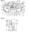
- the web winding apparatus is surrounded by an overall cover 10.
- the overall cover 10 is provided with a fixed cover 11 fixed to a bed (base) 20 and two opening/closing covers 12, 13 each capable of being opened and closed, respectively at left and right on the front side of the fixed cover 11.
- Each of the opening/closing covers 12, 13 is opened when a web W having been wound in the form of a roll shape is taken out, and remains closed while the web W is being wound.
- Figures 1 and 2 show the opening/closing cover 12 on the left side in an open state and the opening/closing cover 13 on the right side in a closed state.
- an opening window 11 a is formed on a right side surface of the fixed cover 11 in order to take inside the web W being transferred to come.
- the web winding apparatus is provided with a first web support device 30, a second wed support device 40, a transfer device 50 and a cutting and joining device 60.
- the first and second web support devices 30, 40 are provided with support bodies 31, 41 (frames), rotational center members 32, 42, bobbins 33, 43 and peripheral covers 34, 44, respectively.
- the support bodies 31, 41 stand upright on the bed 20 on left and right sides of the bed 20 as viewed from the front side.
- the support bodies 31, 41 may be fixed on the bed 20 or may be provided on the bed 20 movably in a front-rear direction (the direction normal to the drawing sheet of Figure 3 ).
- the rotational center members 32, 42 are provided to protrude from front vertical walls of the respective support bodies 31, 41 and to be rotatable about respective axes that extend in the front-rear direction in parallel to each other.
- the rotational center members 32, 42 rotate about the respective axes in the same direction (i.e., clockwise as viewed in Figure 3 ).
- the respective bobbins 33, 43 are detachably supported on the respective rotational center members 32, 42 and each operate to wind thereon the web W transferred to come thereto. That is, since the bobbins 33, 43 rotate about the respective center axes in the same direction (clockwise in Figure 3 ), the directions in which the bobbins 33, 43 wind the web W become the same clockwise in Figure 3 . Further, a double-sided adhesive tape or adhesive agent is applied to a part on each of the bobbins 33, 43 for adhering an end portion of the web W thereto.
- the peripheral covers 34, 44 are provided on the respective support bodies 31, 41 and are turnable in both directions around the rotational center members 32, 42 independently of the same, respectively.
- the peripheral covers 34, 44 cover up parts of the webs W wound respectively on the bobbins 33, 43 and have openings in the circumferential direction thereof. That is, the peripheral covers 34, 44 take the form of a C-letter.
- the peripheral covers 34, 44 are movable to the positions (first positions) where the circumferential openings 34c, 44c face each other and to the positions (second positions) where the circumferential openings 34c, 44c face the bed 20 side (are directed downward in Figure 3 ).
- the peripheral covers 34, 44 are formed to have the exterior shape which is smaller slightly in dimension than the interior shape of the opening/closing covers 12, 13, as illustrated in Figure 1 .
- the transfer device 50 is provided with a first transfer-roller support pedestal 51, a second transfer-roller support pedestal 52, and transfer rollers 51 a, 51 b, 52a-52c that transfer the web W.
- the first transfer-roller support pedestal 51 stands upright on the bed 20 at the right end of the same and rotatably supports the transfer rollers 51 a, 51 b respectively at a center portion and an upper end portion thereof in the vertical direction.
- the second transfer-roller support pedestal 52 stands upright on the bed 20 at a center portion in the left-right direction and rotatably supports the transfer rollers 52a-52c at an upper end portion thereof in the vertical direction.
- the web W transferred to come from outside is transferred to travel on the rollers 51 a, 51 b, 52a, 52b and 52c in turn.
- These transfer rollers 51 a, 51 b, 52a-52c are freely rotatable.
- the transfer roller 52b is supported by a mechanism having a tension adjusting function and is movable slightly relative to the second transfer-roller support pedestal 52.
- the transfer rollers 51 a, 51 b, 52a-52c are designed as freely rotatable rollers, there may be provided one or more rotational driving sources therefor.
- the cutting and joining device 60 is arranged at a center portion between the first and second web support devices 30, 40 in the left-right direction and transfers to one of the bobbins 33, 43 the web W which is transferred by the transfer device 50 from outside to the center portion between the first and second web support devices 30, 40 in the left-right direction. Further, when one of the bobbins 33, 43 is filled with winding turns of the web W, the cutting and joining device 60 cuts the web W and winds a cut end of the web W on the other of the bobbins 33, 43.
- the cutting and joining device 60 is provided with a guide base 61, a slide head 62, a pivot plate 63, a lead roller 64, a cutter unit 65 and a web pressing unit 66.
- the guide base 61 is provided on the bed 20 at a center portion between the support bodies 31, 41 in the left-right direction and has rails 61 a extending in the left-right direction, on an upper surface thereof.
- the guide base 61 is arranged on the front side of the second transfer-roller support pedestal 52.
- the slide head 62 is provided on the upper surface of the guide base 61 slidably along the rails 61 a in the left-right direction. That is, the slide head 62 is slidable between the bobbin 33 on one side and the bobbin 43 on the other side.
- the pivot plate 63 is provided at a front, vertical wall surface of the slide head 62 pivotably in both directions about an axis extending in the front-rear direction.
- the lead roller 64 is provided at the front surface of the pivot plate 63 freely rotatably about an axis extending in the front-rear direction.
- the lead roller 64 is a roller that receives the web W transferred from the transfer roller 52c and transfers the web W toward the bobbins 33, 43.
- the cutter unit 65 is supported by the pivot plate 63 and is able to be drivingly turned relative to the pivot plate 63 in the same direction as the rotational direction of the bobbins 33, 43. That is, the cutter unit 65 is movable between the bobbin 33 on one side and the bobbin 43 in the other side.
- the turn center of the cutter unit 65 is set to be offset from the rotational center of the lead roller 64 as viewed in Figure 3 .
- the cutter unit 65 is provided with a cutter member 65a and first and second rollers 65b, 65c.
- the cutter member 65a has a circular arc convex surface at a radially outside thereof.
- the circular arc convex surface of the cutter member 65a is formed to a circular arc surface centered at the axis for the clockwise turn of the cutter unit 65.
- the cutter member 65a has a cutter T for cutting the web W, at one end portion in the circumferential direction of the circular arc (that is, on an advanced end side in the turn direction).
- the cutter T is wider in width than the web W.
- the first and second rollers 65b, 65c are provided on the back side of the cutter member 65a and are freely rotatable.
- the web pressing unit 66 is supported by the pivot plate 63 and is able to be drivingly turned relative to the pivot plate 63 in an opposite direction (counterclockwise as viewed in Figure 3 ) to the rotational direction of the bobbins 33, 43. That is, the web pressing unit 66 moves together with the cutter unit 65 between the bobbin 33 on one side and the bobbin 43 on the other side.
- the turn center of the web pressing unit 66 is set to be offset from the rotational center of the lead roller 64 and the turn center of the cutter unit 65, as viewed in Figure 3 . Further, the web pressing unit 66 is provided at a position where it faces the cutter unit 65 so as to put the web W transferred from the lead roller 64 between itself and the cutter unit 65.
- the web pressing unit 66 is provided with a web pressing member 66a and first and second rollers 66b, 66c. As shown in Figure 7 , the web pressing member 66a has a circular arc convex surface at the radial outside thereof. The circular arc convex surface of the web pressing member 66a is formed to a circular arc convex surface centered at the center for the counterclockwise turn of the web pressing unit 66. The web pressing member 66a has a groove D that serves as surface to receive the cutter T, around at one end portion in the circumferential direction of the circular arc (i.e., on an advanced end side of the turn direction). In other words, the web pressing member 66a operates as cutter receiving surface.
- the circular arc convex surface of the web pressing member 66a is formed to be located to contact the circular arc convex surface of the cutter member 65a or to have such a slight clearance as to be able to grip the web relative to the circular arc convex surface of the cutter member 65a. That is, the web pressing member 66a operates to press the web W in cooperation with the cutter member 65a so that the web W can be cut by the cutter T. Further, the web pressing member 66a is formed to be located to contact the lead roller 64 or to have such a slight clearance as to be able to grip the web relative to the lead roller 64.
- the web pressing member 66a has pluralities of pump suction holes H1, H2 respectively at the groove D and the circular arc convex surface. These pump suction holes H1, H2 are in fluid communication with a common vacuum pump P, as schematically illustrated in Figure 7 .
- the pump suction holes H1 at the groove D draws dust that is produced at the time of cutting the web W, by the drawing force (vacuum force) of the pump P (dust drawing means).
- the pump suction holes H2 at the circular arc convex surface draws and holds the cut end of the web W so cut, by the drawing force of the pump P (holding means).
- the suction holes H1 at the groove D also operate to hold the cut end of the web W in addition to the dust drawing operation.
- the downsizing can be realized by using the common pump P for the dust drawing and for the holding of the web W. Further, by using the drawing force of the pump P for the both means, the web pressing member 66a becomes simple in construction.
- drawing force by the pump P there may be used a drawing force by static electricity and a drawing force by magnetic force for the function of holding the cut end of the web W.
- static electricity it is preferable for example to use a low-conductivity material such as resin, ceramics or the like for the cutter member 65a and to use a high-conductivity material such as metal or the like for the web pressing member 66a.
- the web pressing member 66a presses the circular arc convex surface on the bobbin 33/43 being empty in the state that it continues holding the cut end of the web W. As a consequence, the cut end of the web W is pressed on the empty bobbin 33/43, so that there begins a winding of the cut end of the web W on the empty bobbin 33/43.
- the first and second rollers 66b, 66c of the web pressing unit 66 are provided on the back side of the web pressing member 66a and are freely rotatable.
- the second roller 66c operates as touch roller so that during the winding of the web W on the bobbin 33/43, the wed W transferred from the lead roller 64 to the bobbin 33/43 side is wound always at a fixed angle relative to the outer peripheral surface of the bobbin 33/43 and the outer peripheral surface of the wound web W.
- the lead roller 64, the cutter unit 65 and the web pressing unit 66 are rotatably supported by the pivot plate 63. Therefore, by pivoting the pivot plate 63 in both directions, there occurs a state that the web pressing unit 66 is rocked as viewed with the cutter unit 65 taken as reference.
- FIG. 3 The state shown in Figure 3 is supposed as initial state.
- the web winding apparatus involves an operation to start the winding of the web W on the bobbin 33/43 being empty and to bring the bobbin 33/43 into the state of being filled with winding turns of the web W (web winding operation) and another operation to dismount the filled-up bobbin 33/43 (bobbin dismounting operation).
- web winding operation will be described first, and the bobbin dismounting operation will be described then.
- the left bobbin 33 is winding the web W and is just before the winding completion.
- the slide head 62 is almost at the center between the bobbins 33, 43.
- the peripheral covers 34, 44 have been positioned to make the circumferential openings 34c, 44c thereof face each other, that is, to direct the circumferential openings 34c, 44c thereof toward the lead roller 64.
- the operation is started to cut the web W without stopping the transfer of the web W and to wind the end portion of the cut web W on the right bobbin 43 being empty.
- the pivot plate 63 is pivoted counterclockwise to reach a set phase and directs the cutter unit 65 and the web pressing unit 66 toward the right bobbin 43 side, as shown in Figure 8 .
- the slide head 62 is moved toward the right bobbin 43 side to make the cutter unit 65 and the web pressing unit 66 come close to the right bobbin 43.
- the lead roller 64 and the second and first rollers 65c, 65b of the cutter unit 65 transfer the web W toward the bobbin 33 side.
- the cutter unit 65 and the web pressing unit 66 are synchronously turned further in the mutually opposite directions.
- the web W is pressed between the circular arc convex surface of the cutter member 65a and the circular arc convex surface of the web pressing member 66a to be held on the web pressing member 66a.
- the cutter T on the cutter member 65a enters the groove D on the web pressing member 66a to cut the web W existing therebetween.
- the cut end of the web W so cut is held by the cutter member 65a and the web pressing member 66a.
- the vacuum pump P being in fluid communication with the web pressing member 66a is driven to draw dust produced at the time of cutting the web W, through the pump suction holes H1 at the groove D on the web pressing member 66a.
- the drawing vacuum force through the pump suction holes H2 at the circular arc convex surface of the web pressing member 66a acts to draw and hold the end portion including the cut end of the web W so cut.
- the cutter unit 65 and the web pressing unit 66 are synchronously turned further in the mutually opposite directions, and the right bobbin 43 is rotated synchronously with the turn of the web pressing unit 66 in the opposite direction to the turn of the web pressing unit 66.
- This causes the web pressing member 66a to press the cut end of the web W on the right bobbin 43. Since at this time, the double-sided adhesive tape or adhesive on the right bobbin 43 is at the position facing the web pressing member 66a, the cut end of the web W begins to be wound on the right bobbin 43.
- the web pressing member 66a has the function of holding the cut end of the web W and the function of pressing the web W on the right bobbin 43. Accordingly, the web pressing member 66a is able to directly press the cut end of the web W on the right bobbin 43 as it keeps the state of holding the cut end of the web W. Thus, the cut end of the web W can reliably be wound by the web pressing member 66a on the right bobbin 43. As a result, the end portion (including the cut end) of the web W can be prevented from being folded or loosened when would on the right bobbin 43.
- the cutter unit 65 and the web pressing unit 66 are synchronously turned further in the mutually opposite directions, and the turns of the both units 65, 66 are stopped at such a position that the second roller 66c of the web pressing unit 66 presses the outer peripheral surface of the right bobbin 43. While the web W is wound on the right bobbin 43, the second roller 66c remains pressing the outer peripheral surface of the wound web W.
- the second roller 66c operates as touch roller that presses the outer peripheral surface of the wound web W. That is, from right after the turn of the web pressing member 66a, the second roller 66c acts to press the outer peripheral surface of the web W. Accordingly, the winding of the web W on the right bobbin 43 is carried out stably. For example, it can be prevented to involve the air or the like.
- the right bobbin 43 becomes filled with winding turns of the web W, as shown in Figure 15 .
- the second roller 66c remains pressed on the outer peripheral surface of the web W being wound on the right bobbin 43.
- the slide head 62 is moved toward the left bobbin 33 side to the position where the pivot plate 63 is pivotable, and the pivot plate 63 is pivoted clockwise to take another set phase. Then, the cutter unit 65 and the web pressing unit 66 are directed toward the left bobbin 33 being empty. Further, the slide head 62 is moved toward the left bobbin 33 side to make the cutter unit 65 and the web pressing unit 66 come close to the left bobbin 33.
- the same operations as done with the right bobbin 43 are carried out in turn with the left bobbin 33, as shown in Figures 17 to 21 . Since like the right bobbin 43, the left bobbin 33 is rotated also clockwise, the web pressing member 66a in winding the end portion of the web W on the left bobbin 33 is located at the advanced side in the rotational phase of the left bobbin 43 relative to the cutter T of the cutter member 65a.
- the peripheral cover 34 stands in position to partition the left bobbin 33 side and the lead roller 64 side (corresponding to the side where the cutter unit 65 and the web pressing unit 66 stand). At this time, the periphery cover 34 also stands in position to partition the left bobbin 33 side and the side where the transfer rollers 51 a, 51 b, 52a-52c stand.
- the opening/closing cover 12 on the left side is opened as shown in Figure 1 . Then, the operator dismounts the left bobbin 33 having been filled with winding turns of the web W from the rotational center member 32. During this time, the web W is being wound on the right bobbin 43, and the opening/closing cover 13 on the right side remains closed.
- the lead roller 64, the cutter unit 65 and the web pressing unit 66 can be evacuated to the right side through the sliding movement of the slide head 62, it becomes possible to dismount the left bobbin 33 from the rotational center member 32 without moving the center of the left bobbin 33. Accordingly, the dismounting of the bobbin 33 can be realized by the simplified construction.
- the peripheral cover 34 is configured to have the circumferential opening 34c.
- the web W can pass through the circumferential opening 34c of the peripheral cover 34. Therefore, the peripheral cover 34 does not constitute any obstacle in the winding of the web W on the bobbin 33.
- the peripheral cover 34 In dismounting the left bobbin 33 from the rotational center member 32, on the other hand, the peripheral cover 34 is turned, whereby the peripheral cover 34 acts to partition the bobbin 33 side and the side where the lead roller 64 and the web W being transferred are located. Accordingly, the operator can safely dismount the bobbin 33 from the rotational center member 32.
- the degree of safety can be increased by designing the contour of a cover area of the opening/closing cover 12 to that resembled closely to, or somewhat larger than, the outer shape of the peripheral cover 34.
- the right opening/closing cover 13 whose cover area has a contour somewhat larger than the outer shape of the peripheral cover 44 remains covering the front side in the axial direction of the right bobbin 43 on which the web W is being wound. Therefore, the operator is prevented by the fixed cover 11, the right opening/closing cover 13 and the left peripheral cover 34 from touching the web W being transferred onto the right bobbin 43.
- the opening/closing covers 12, 13 and the peripheral covers 34, 44 may be performed manually.
- the operations are performed by, for example, the mechanisms which will be described hereafter with reference to Figures 1-3 and 5.
- the opening/closing covers 12, 13 are provided at opposite sidewall portions in the left-right direction in Figure 1 with hook members 12a, 13a extending outward.
- the hook members 12a, 13a have elongate slots (not numbered) and, with the opening/closing covers 12, 13 closed, are bent forward through an angle of about 45 degrees when viewed from above.
- pneumatic linear-motion cylinders 14, 15 whose piston rods are engaged with the hook members 12a, 13a at forward ends thereof, respectively. More specifically, the forward end of each piston rod passes through the elongate slot and puts the hook member 12a/13a between a pair of flanges 14b/15b provided at the forward end thereof. Therefore, by the operations of the linear-motion cylinders 14, 15, the opening/closing covers 12, 13 are pivotable about hinges 12b, 12b and 13b, 13b through an angle of 90 degrees or more between the closed position and the open position.
- the peripheral covers 34, 44 are supported to be turnable around the respective rotational center members 32, 42, as mentioned earlier. As shown in Figures 3 and 5 , the peripheral covers 34, 44 are coaxially provided with driven gears 34a, 44a, which are in driving connection with drive gears 17a, 18a fixed on output shafts of pneumatic rotary actuators 17, 18, through respective timing belts 17b, 18b. Thus, by the operations of the rotary actuators 17, 18, the peripheral covers 34, 44 are independently turned through an angle of about 90 degrees between the aforementioned first position to direct the circumferential openings 34c, 44c toward the cutting and joining device 60 and the aforementioned second position to direct the circumferential openings 34c, 44c toward the bed 20, as mentioned earlier.
- the opening/closed cover 12 is turned to the closed position to close the front side of the new empty bobbin 33 on the rotational center member 32, and the peripheral cover 34 is then turned counterclockwise to direct the circumferential opening 34c toward the cutting and joining device 60, whereby the new empty bobbin 33 become ready for the winding operation.
- linear-motion cylinders 14, 15 and the rotary actuators 17, 18 which are, preferably, of the pneumatically operated type are used, they may be of the type that are hydraulically operated or electrically actuated. Further, linkage mechanisms that connect the operations of the actuators 17, 18 and the cylinders 14, 15 to the peripheral covers 34, 44 and the opening/closing covers 12, 13 may take various kinds of mechanisms without being limited to the gear to gear belt connection and to the engagements with the hook members 12a, 13a.
- the support bodies 31, 41 of the first and second web support devices 30, 40 are fixed on the bed 20, the support bodies 31, 41 may be movable relative to the bed 20 in the front-read direction. By doing so, it becomes possible to advance the support devices 30, 40 forward in dismounting the bobbin 33/43 from the rotational center member 32/42, so that the dismounting work becomes easy.
- the cutter T, the web pressing member 66a and the roller 64 are movable between the two bobbins 33, 43. Then, when the winding of the web W on each bobbin 33/43 is completed, the cutter T, the web pressing member 66a and the roller 64 are evacuated, so that it becomes possible to dismount each such bobbin 33/43 from the rotational center member 32/42 without moving the same. Accordingly, it is not required to provide a large-scale transfer device as is required in the prior art, and hence, the transfer device can be simplified in construction though being able to continuously transfer the web W.
- the apparatus is provided with the peripheral covers 34, 44 having the circumferential openings 34c, 44c.
- the web W is enabled to pass through the circumferential opening 34c/44c of the peripheral cover 34/44 mating with each such bobbin 33/43. Therefore, the peripheral covers 34, 44 do not impede the winding of the web W on the bobbin 33/43 mating therewith.
- the peripheral cover 34/44 mating with each such bobbin 33/43 is turned to partition the roller 64 side and the bobbin 33/43 side. Accordingly, the operator can safely dismount each bobbin 33/43 from the rotational center member 32/42.
- the peripheral cover 34/44 covering the bobbin 33/43 to be dismounted stands at the second position to partition the one side of the bobbins 33, 43 and the side where the web W is being transferred to the other bobbin 33/43. This enables the operator to dismount the bobbin 33/43 from one of the rotational center members 32, 42 further safely.
- the two peripheral covers 34, 44 have front sides opened to enable the bobbins 33, 43 to be dismounted respectively from front sides of the peripheral covers 34, 44 by being moved in the axial direction of the rotational center members 32, 42. Therefore, during the winding of the web W on one of the bobbins 33, 43, the operator can easily dismount the other of the bobbins 33, 43 from the front side of the peripheral cover 34/44 mating therewith safely with the peripheral cover 34/44 partitioning a dismounting operation area and an ongoing winding operation area.
- the two opening/closing covers 12, 13 are provided for respectively covering the front sides of the two peripheral covers 34, 44.
- the front side in the axial direction of the other bobbin 43/33 on which the web W is being wound remains closed by the opening/closing cover 13/12 mating therewith.
- the operator can further safely dismount the bobbin 33/43 from the rotational center member 32/42 during the winding of the web W on the other bobbin 43/33.
- a web winding apparatus comprises a cutter (T), a web pressing member (66a) and a roller (64) which are movable together between two bobbins (33, 43) supported respectively by two rotational center members (32, 42).
- the cutter (T) cuts a web (W) being transferred
- the web pressing member (66a) presses an end portion of the web (W) cut with the cutter (T) on the bobbin (33/43) being empty
- the roller (64) transfers the web (W) being transferred to come, toward the bobbins (33, 43).
- the apparatus further comprises two peripheral covers (34, 44) independently turnable around the rotational center members (32, 42) and respectively covering parts of outer peripheral surfaces of the webs (W) wound on the two bobbins (33, 43).
- Each of the peripheral covers (34, 44) respectively having circumferential openings (34c, 44c) is turnable selectively to a first position to direct the circumferential opening (34c/44c) toward the roller (64) and a second position to partition the bobbin (33/43) side covered thereby and the roller (64) side.
Landscapes
- Engineering & Computer Science (AREA)
- General Engineering & Computer Science (AREA)
- Mechanical Engineering (AREA)
- Physics & Mathematics (AREA)
- Fluid Mechanics (AREA)
- Replacement Of Web Rolls (AREA)
- Winding Of Webs (AREA)
Applications Claiming Priority (1)
| Application Number | Priority Date | Filing Date | Title |
|---|---|---|---|
| JP2012069297A JP5840047B2 (ja) | 2012-03-26 | 2012-03-26 | ウエブ巻取装置 |
Publications (3)
| Publication Number | Publication Date |
|---|---|
| EP2644543A2 true EP2644543A2 (de) | 2013-10-02 |
| EP2644543A3 EP2644543A3 (de) | 2014-03-19 |
| EP2644543B1 EP2644543B1 (de) | 2015-05-06 |
Family
ID=47891471
Family Applications (1)
| Application Number | Title | Priority Date | Filing Date |
|---|---|---|---|
| EP20130159354 Not-in-force EP2644543B1 (de) | 2012-03-26 | 2013-03-15 | Bahnaufrollvorrichtung |
Country Status (5)
| Country | Link |
|---|---|
| US (1) | US8991739B2 (de) |
| EP (1) | EP2644543B1 (de) |
| JP (1) | JP5840047B2 (de) |
| KR (1) | KR101980179B1 (de) |
| CN (1) | CN103359510B (de) |
Cited By (1)
| Publication number | Priority date | Publication date | Assignee | Title |
|---|---|---|---|---|
| ITUA20163344A1 (it) * | 2016-05-11 | 2017-11-11 | Celli Nonwovens Spa | Macchina e metodo per l'avvolgimento di strisce di materiale nastriforme con mezzi per il taglio trasversale delle strisce e ancoraggio delle strisce all'anima di avvolgimento |
Families Citing this family (7)
| Publication number | Priority date | Publication date | Assignee | Title |
|---|---|---|---|---|
| US9187285B2 (en) * | 2012-11-19 | 2015-11-17 | Valmet Technologies, Inc. | Slitter-winder of a fiber production line |
| JP6707518B2 (ja) * | 2014-08-01 | 2020-06-10 | アンジェロ・ドッタ | 工作機械へ給送するために特に適したリール交換装置 |
| JP2018065657A (ja) * | 2016-10-19 | 2018-04-26 | セイコーエプソン株式会社 | 巻取装置及び印刷装置 |
| CN108792701B (zh) * | 2018-07-18 | 2024-01-26 | 山东奥海纸业有限公司 | 一种卷纸设备 |
| DE102019129167A1 (de) | 2018-11-28 | 2020-05-28 | Samsung Electronics Co., Ltd. | Betriebsverfahren eines Endgeräts in einem Drahtlos-Kommunikationssystem und Endgerät zum Durchführen des Verfahrens |
| JP7450934B2 (ja) | 2021-03-12 | 2024-03-18 | 大森機械工業株式会社 | フィルム供給装置 |
| KR102568427B1 (ko) * | 2023-05-09 | 2023-08-21 | 주식회사 아민 | 박형 제조물의 권취 장치, 권취 방법 및 권취 시스템 |
Citations (9)
| Publication number | Priority date | Publication date | Assignee | Title |
|---|---|---|---|---|
| US2767931A (en) * | 1952-08-29 | 1956-10-23 | John L Woods | Webbing dispensing apparatus |
| US4282963A (en) * | 1979-05-03 | 1981-08-11 | Hammermill Paper Company | Barrier guard |
| US6059216A (en) * | 1997-12-17 | 2000-05-09 | Tenryu Technics Co., Ltd. | Taping member supporting device for an electronic component feeding apparatus |
| EP1174375A2 (de) * | 2000-07-21 | 2002-01-23 | REHAU AG + Co | Vorrichtung zur Aufnahme und Abgabe von Profilen und deren Verwendung |
| EP1619156A1 (de) * | 2004-07-21 | 2006-01-25 | Voith Paper Patent GmbH | Vorrichtung zum Abwickeln einer Materialbahn von einer auf einer Wickelachse gelagerten Wickelrolle |
| EP1717178A2 (de) * | 2005-04-27 | 2006-11-02 | Voith Patent GmbH | Wickelmaschine zum Aufwickeln einer Materialbahn |
| DE102005000044A1 (de) * | 2005-04-27 | 2006-11-02 | Voith Patent Gmbh | Doppeltragwalzen-Wickelmaschine |
| DE102007001671B3 (de) * | 2007-01-11 | 2008-03-06 | Koenig & Bauer Aktiengesellschaft | Schutzvorrichtung beim Hülsenbersten |
| EP2251290A1 (de) * | 2009-05-14 | 2010-11-17 | WIFAG Maschinenfabrik AG | Hülsenbruchstück-Rückhaltevorrichtung an einem Rollenwechsler |
Family Cites Families (12)
| Publication number | Priority date | Publication date | Assignee | Title |
|---|---|---|---|---|
| US1575088A (en) * | 1925-03-18 | 1926-03-02 | Richard Spry | Guard for paper-winding machines |
| JPS506818A (de) | 1973-06-01 | 1975-01-24 | ||
| DE2724955C2 (de) * | 1977-06-02 | 1983-03-24 | Erwin Kampf Gmbh & Co Maschinenfabrik, 5276 Wiehl | Rollenwickelmaschine zur Bildung von Einzelwickeln |
| DE3937286A1 (de) * | 1989-11-09 | 1991-05-16 | Hoechst Ag | Bandwechselvorrichtung |
| JP2807857B2 (ja) | 1993-10-04 | 1998-10-08 | 株式会社ヒラノテクシード | ウエブの巻取装置 |
| JPH0728139U (ja) * | 1993-10-29 | 1995-05-23 | ホシザキ電機株式会社 | 巻きおしぼり製造装置 |
| JPH07234601A (ja) * | 1994-02-23 | 1995-09-05 | Ricoh Co Ltd | 定着ローラのクリーニング装置 |
| JP3506818B2 (ja) | 1995-08-23 | 2004-03-15 | 東芝電池株式会社 | 電池用電極シートの巻付装置および同巻付方法 |
| JP2001088992A (ja) * | 1999-09-27 | 2001-04-03 | Hitachi Zosen Corp | 巻取機の枠替え装置 |
| US6588698B2 (en) * | 2001-11-26 | 2003-07-08 | Gl&V Management Hungary Kft | Winding machine including a finger sensor adjacent the nip formed between a support drum and a web reel |
| US6616085B2 (en) * | 2002-02-12 | 2003-09-09 | Metso Paper, Inc. | Winder splicing nip guard |
| WO2008047546A1 (fr) * | 2006-09-29 | 2008-04-24 | Hitachi Chemical Company, Ltd. | Dispositif d'enroulement de film automatique, système de refendage et d'enroulement et procédé de fabrication d'un film enroulé |
-
2012
- 2012-03-26 JP JP2012069297A patent/JP5840047B2/ja active Active
-
2013
- 2013-02-18 KR KR1020130016946A patent/KR101980179B1/ko active IP Right Grant
- 2013-03-08 US US13/790,232 patent/US8991739B2/en active Active
- 2013-03-15 EP EP20130159354 patent/EP2644543B1/de not_active Not-in-force
- 2013-03-18 CN CN201310085588.0A patent/CN103359510B/zh active Active
Patent Citations (9)
| Publication number | Priority date | Publication date | Assignee | Title |
|---|---|---|---|---|
| US2767931A (en) * | 1952-08-29 | 1956-10-23 | John L Woods | Webbing dispensing apparatus |
| US4282963A (en) * | 1979-05-03 | 1981-08-11 | Hammermill Paper Company | Barrier guard |
| US6059216A (en) * | 1997-12-17 | 2000-05-09 | Tenryu Technics Co., Ltd. | Taping member supporting device for an electronic component feeding apparatus |
| EP1174375A2 (de) * | 2000-07-21 | 2002-01-23 | REHAU AG + Co | Vorrichtung zur Aufnahme und Abgabe von Profilen und deren Verwendung |
| EP1619156A1 (de) * | 2004-07-21 | 2006-01-25 | Voith Paper Patent GmbH | Vorrichtung zum Abwickeln einer Materialbahn von einer auf einer Wickelachse gelagerten Wickelrolle |
| EP1717178A2 (de) * | 2005-04-27 | 2006-11-02 | Voith Patent GmbH | Wickelmaschine zum Aufwickeln einer Materialbahn |
| DE102005000044A1 (de) * | 2005-04-27 | 2006-11-02 | Voith Patent Gmbh | Doppeltragwalzen-Wickelmaschine |
| DE102007001671B3 (de) * | 2007-01-11 | 2008-03-06 | Koenig & Bauer Aktiengesellschaft | Schutzvorrichtung beim Hülsenbersten |
| EP2251290A1 (de) * | 2009-05-14 | 2010-11-17 | WIFAG Maschinenfabrik AG | Hülsenbruchstück-Rückhaltevorrichtung an einem Rollenwechsler |
Cited By (3)
| Publication number | Priority date | Publication date | Assignee | Title |
|---|---|---|---|---|
| ITUA20163344A1 (it) * | 2016-05-11 | 2017-11-11 | Celli Nonwovens Spa | Macchina e metodo per l'avvolgimento di strisce di materiale nastriforme con mezzi per il taglio trasversale delle strisce e ancoraggio delle strisce all'anima di avvolgimento |
| EP3243777A1 (de) * | 2016-05-11 | 2017-11-15 | A.Celli Nonwovens S.P.A. | Maschine und verfahren zum aufwickeln von bahnmaterialstreifen mit mitteln zum querschneiden der streifen und zum verankern der streifen am wickelkern |
| US10526156B2 (en) | 2016-05-11 | 2020-01-07 | A. Celli Nonwovens S.P.A. | Machine and method for the winding of strips of web material with means for transversal cutting of the strips and anchoring of the strips to the winding core |
Also Published As
| Publication number | Publication date |
|---|---|
| EP2644543B1 (de) | 2015-05-06 |
| CN103359510A (zh) | 2013-10-23 |
| JP2013199358A (ja) | 2013-10-03 |
| US8991739B2 (en) | 2015-03-31 |
| KR101980179B1 (ko) | 2019-05-20 |
| KR20130109028A (ko) | 2013-10-07 |
| US20130248640A1 (en) | 2013-09-26 |
| CN103359510B (zh) | 2016-09-14 |
| JP5840047B2 (ja) | 2016-01-06 |
| EP2644543A3 (de) | 2014-03-19 |
Similar Documents
| Publication | Publication Date | Title |
|---|---|---|
| EP2644543B1 (de) | Bahnaufrollvorrichtung | |
| US9102490B2 (en) | Web winding apparatus | |
| WO2013097277A1 (zh) | 双工位同时收卷装置 | |
| CN203950879U (zh) | 一种圆柱电池卷绕机 | |
| CN111056347A (zh) | 自动换卷装置及卷绕设备 | |
| JP2011241017A (ja) | テープ巻取装置 | |
| CN113003269A (zh) | 一种飞刀型自动驳接收卷装置 | |
| CN211870895U (zh) | 接带机构、自动换卷装置及卷绕设备 | |
| CN211870896U (zh) | 自动换卷装置及卷绕设备 | |
| CN211594402U (zh) | 备料机构、自动换卷装置及卷绕设备 | |
| CN217172599U (zh) | 一种离型膜收卷与分切装置 | |
| CN112271320B (zh) | 卷绕机 | |
| CN206437679U (zh) | 卷绕机构及复卷机 | |
| CN215248440U (zh) | 一种飞刀型自动驳接收卷装置 | |
| CN210884465U (zh) | 一种便捷式脱离的卷材设备 | |
| CN110424144A (zh) | 一种全自动多层布匹铺设裁床 | |
| JP7074736B2 (ja) | 巻芯支持装置と巻芯回転装置 | |
| CN218319711U (zh) | 一种收卷装置 | |
| CN210192919U (zh) | 一种双层离型膜胶带加工用卷绕装置 | |
| JP2509836B2 (ja) | スリッタ―装置 | |
| CN212197736U (zh) | 放卷机构、自动换卷装置及卷绕设备 | |
| CN214495036U (zh) | 一种喷墨印刷机的双工位收卷装置 | |
| CN216708361U (zh) | 一种用于汽车离合器包装的自动覆膜机构 | |
| ES2460765B1 (es) | Unidad desbobinadora/rebobinadora para máquina de tratamiento de banda de lámina | |
| WO2014057143A1 (es) | Unidad desbobinadora/rebobinadora de banda de lámina |
Legal Events
| Date | Code | Title | Description |
|---|---|---|---|
| PUAI | Public reference made under article 153(3) epc to a published international application that has entered the european phase |
Free format text: ORIGINAL CODE: 0009012 |
|
| AK | Designated contracting states |
Kind code of ref document: A2 Designated state(s): AL AT BE BG CH CY CZ DE DK EE ES FI FR GB GR HR HU IE IS IT LI LT LU LV MC MK MT NL NO PL PT RO RS SE SI SK SM TR |
|
| AX | Request for extension of the european patent |
Extension state: BA ME |
|
| PUAL | Search report despatched |
Free format text: ORIGINAL CODE: 0009013 |
|
| AK | Designated contracting states |
Kind code of ref document: A3 Designated state(s): AL AT BE BG CH CY CZ DE DK EE ES FI FR GB GR HR HU IE IS IT LI LT LU LV MC MK MT NL NO PL PT RO RS SE SI SK SM TR |
|
| AX | Request for extension of the european patent |
Extension state: BA ME |
|
| RIC1 | Information provided on ipc code assigned before grant |
Ipc: B65H 19/22 20060101ALI20140211BHEP Ipc: F16P 1/04 20060101ALI20140211BHEP Ipc: B65H 19/26 20060101ALI20140211BHEP Ipc: B65H 19/28 20060101AFI20140211BHEP Ipc: B65H 19/30 20060101ALI20140211BHEP |
|
| 17P | Request for examination filed |
Effective date: 20140826 |
|
| GRAP | Despatch of communication of intention to grant a patent |
Free format text: ORIGINAL CODE: EPIDOSNIGR1 |
|
| INTG | Intention to grant announced |
Effective date: 20141121 |
|
| GRAS | Grant fee paid |
Free format text: ORIGINAL CODE: EPIDOSNIGR3 |
|
| GRAA | (expected) grant |
Free format text: ORIGINAL CODE: 0009210 |
|
| AK | Designated contracting states |
Kind code of ref document: B1 Designated state(s): AL AT BE BG CH CY CZ DE DK EE ES FI FR GB GR HR HU IE IS IT LI LT LU LV MC MK MT NL NO PL PT RO RS SE SI SK SM TR |
|
| REG | Reference to a national code |
Ref country code: GB Ref legal event code: FG4D |
|
| REG | Reference to a national code |
Ref country code: CH Ref legal event code: EP |
|
| REG | Reference to a national code |
Ref country code: IE Ref legal event code: FG4D |
|
| REG | Reference to a national code |
Ref country code: AT Ref legal event code: REF Ref document number: 725535 Country of ref document: AT Kind code of ref document: T Effective date: 20150615 |
|
| REG | Reference to a national code |
Ref country code: DE Ref legal event code: R096 Ref document number: 602013001660 Country of ref document: DE Effective date: 20150625 |
|
| REG | Reference to a national code |
Ref country code: AT Ref legal event code: MK05 Ref document number: 725535 Country of ref document: AT Kind code of ref document: T Effective date: 20150506 |
|
| REG | Reference to a national code |
Ref country code: NL Ref legal event code: MP Effective date: 20150506 |
|
| REG | Reference to a national code |
Ref country code: LT Ref legal event code: MG4D |
|
| PG25 | Lapsed in a contracting state [announced via postgrant information from national office to epo] |
Ref country code: LT Free format text: LAPSE BECAUSE OF FAILURE TO SUBMIT A TRANSLATION OF THE DESCRIPTION OR TO PAY THE FEE WITHIN THE PRESCRIBED TIME-LIMIT Effective date: 20150506 Ref country code: NO Free format text: LAPSE BECAUSE OF FAILURE TO SUBMIT A TRANSLATION OF THE DESCRIPTION OR TO PAY THE FEE WITHIN THE PRESCRIBED TIME-LIMIT Effective date: 20150806 Ref country code: HR Free format text: LAPSE BECAUSE OF FAILURE TO SUBMIT A TRANSLATION OF THE DESCRIPTION OR TO PAY THE FEE WITHIN THE PRESCRIBED TIME-LIMIT Effective date: 20150506 Ref country code: FI Free format text: LAPSE BECAUSE OF FAILURE TO SUBMIT A TRANSLATION OF THE DESCRIPTION OR TO PAY THE FEE WITHIN THE PRESCRIBED TIME-LIMIT Effective date: 20150506 Ref country code: PT Free format text: LAPSE BECAUSE OF FAILURE TO SUBMIT A TRANSLATION OF THE DESCRIPTION OR TO PAY THE FEE WITHIN THE PRESCRIBED TIME-LIMIT Effective date: 20150907 Ref country code: ES Free format text: LAPSE BECAUSE OF FAILURE TO SUBMIT A TRANSLATION OF THE DESCRIPTION OR TO PAY THE FEE WITHIN THE PRESCRIBED TIME-LIMIT Effective date: 20150506 |
|
| PG25 | Lapsed in a contracting state [announced via postgrant information from national office to epo] |
Ref country code: IS Free format text: LAPSE BECAUSE OF FAILURE TO SUBMIT A TRANSLATION OF THE DESCRIPTION OR TO PAY THE FEE WITHIN THE PRESCRIBED TIME-LIMIT Effective date: 20150906 Ref country code: RS Free format text: LAPSE BECAUSE OF FAILURE TO SUBMIT A TRANSLATION OF THE DESCRIPTION OR TO PAY THE FEE WITHIN THE PRESCRIBED TIME-LIMIT Effective date: 20150506 Ref country code: GR Free format text: LAPSE BECAUSE OF FAILURE TO SUBMIT A TRANSLATION OF THE DESCRIPTION OR TO PAY THE FEE WITHIN THE PRESCRIBED TIME-LIMIT Effective date: 20150807 Ref country code: LV Free format text: LAPSE BECAUSE OF FAILURE TO SUBMIT A TRANSLATION OF THE DESCRIPTION OR TO PAY THE FEE WITHIN THE PRESCRIBED TIME-LIMIT Effective date: 20150506 Ref country code: AT Free format text: LAPSE BECAUSE OF FAILURE TO SUBMIT A TRANSLATION OF THE DESCRIPTION OR TO PAY THE FEE WITHIN THE PRESCRIBED TIME-LIMIT Effective date: 20150506 Ref country code: BG Free format text: LAPSE BECAUSE OF FAILURE TO SUBMIT A TRANSLATION OF THE DESCRIPTION OR TO PAY THE FEE WITHIN THE PRESCRIBED TIME-LIMIT Effective date: 20150806 |
|
| PG25 | Lapsed in a contracting state [announced via postgrant information from national office to epo] |
Ref country code: DK Free format text: LAPSE BECAUSE OF FAILURE TO SUBMIT A TRANSLATION OF THE DESCRIPTION OR TO PAY THE FEE WITHIN THE PRESCRIBED TIME-LIMIT Effective date: 20150506 Ref country code: EE Free format text: LAPSE BECAUSE OF FAILURE TO SUBMIT A TRANSLATION OF THE DESCRIPTION OR TO PAY THE FEE WITHIN THE PRESCRIBED TIME-LIMIT Effective date: 20150506 |
|
| REG | Reference to a national code |
Ref country code: DE Ref legal event code: R097 Ref document number: 602013001660 Country of ref document: DE |
|
| PG25 | Lapsed in a contracting state [announced via postgrant information from national office to epo] |
Ref country code: PL Free format text: LAPSE BECAUSE OF FAILURE TO SUBMIT A TRANSLATION OF THE DESCRIPTION OR TO PAY THE FEE WITHIN THE PRESCRIBED TIME-LIMIT Effective date: 20150506 Ref country code: SK Free format text: LAPSE BECAUSE OF FAILURE TO SUBMIT A TRANSLATION OF THE DESCRIPTION OR TO PAY THE FEE WITHIN THE PRESCRIBED TIME-LIMIT Effective date: 20150506 Ref country code: RO Free format text: LAPSE BECAUSE OF NON-PAYMENT OF DUE FEES Effective date: 20150506 Ref country code: CZ Free format text: LAPSE BECAUSE OF FAILURE TO SUBMIT A TRANSLATION OF THE DESCRIPTION OR TO PAY THE FEE WITHIN THE PRESCRIBED TIME-LIMIT Effective date: 20150506 |
|
| PLBE | No opposition filed within time limit |
Free format text: ORIGINAL CODE: 0009261 |
|
| STAA | Information on the status of an ep patent application or granted ep patent |
Free format text: STATUS: NO OPPOSITION FILED WITHIN TIME LIMIT |
|
| 26N | No opposition filed |
Effective date: 20160209 |
|
| PG25 | Lapsed in a contracting state [announced via postgrant information from national office to epo] |
Ref country code: IT Free format text: LAPSE BECAUSE OF FAILURE TO SUBMIT A TRANSLATION OF THE DESCRIPTION OR TO PAY THE FEE WITHIN THE PRESCRIBED TIME-LIMIT Effective date: 20150506 |
|
| PG25 | Lapsed in a contracting state [announced via postgrant information from national office to epo] |
Ref country code: SI Free format text: LAPSE BECAUSE OF FAILURE TO SUBMIT A TRANSLATION OF THE DESCRIPTION OR TO PAY THE FEE WITHIN THE PRESCRIBED TIME-LIMIT Effective date: 20150506 |
|
| PG25 | Lapsed in a contracting state [announced via postgrant information from national office to epo] |
Ref country code: BE Free format text: LAPSE BECAUSE OF FAILURE TO SUBMIT A TRANSLATION OF THE DESCRIPTION OR TO PAY THE FEE WITHIN THE PRESCRIBED TIME-LIMIT Effective date: 20150506 |
|
| PG25 | Lapsed in a contracting state [announced via postgrant information from national office to epo] |
Ref country code: MC Free format text: LAPSE BECAUSE OF FAILURE TO SUBMIT A TRANSLATION OF THE DESCRIPTION OR TO PAY THE FEE WITHIN THE PRESCRIBED TIME-LIMIT Effective date: 20150506 Ref country code: LU Free format text: LAPSE BECAUSE OF FAILURE TO SUBMIT A TRANSLATION OF THE DESCRIPTION OR TO PAY THE FEE WITHIN THE PRESCRIBED TIME-LIMIT Effective date: 20160315 |
|
| REG | Reference to a national code |
Ref country code: CH Ref legal event code: PL |
|
| REG | Reference to a national code |
Ref country code: IE Ref legal event code: MM4A |
|
| REG | Reference to a national code |
Ref country code: FR Ref legal event code: ST Effective date: 20161130 |
|
| PG25 | Lapsed in a contracting state [announced via postgrant information from national office to epo] |
Ref country code: IE Free format text: LAPSE BECAUSE OF NON-PAYMENT OF DUE FEES Effective date: 20160315 Ref country code: FR Free format text: LAPSE BECAUSE OF NON-PAYMENT OF DUE FEES Effective date: 20160331 Ref country code: CH Free format text: LAPSE BECAUSE OF NON-PAYMENT OF DUE FEES Effective date: 20160331 Ref country code: LI Free format text: LAPSE BECAUSE OF NON-PAYMENT OF DUE FEES Effective date: 20160331 |
|
| PG25 | Lapsed in a contracting state [announced via postgrant information from national office to epo] |
Ref country code: SE Free format text: LAPSE BECAUSE OF FAILURE TO SUBMIT A TRANSLATION OF THE DESCRIPTION OR TO PAY THE FEE WITHIN THE PRESCRIBED TIME-LIMIT Effective date: 20150506 Ref country code: NL Free format text: LAPSE BECAUSE OF FAILURE TO SUBMIT A TRANSLATION OF THE DESCRIPTION OR TO PAY THE FEE WITHIN THE PRESCRIBED TIME-LIMIT Effective date: 20150506 |
|
| PG25 | Lapsed in a contracting state [announced via postgrant information from national office to epo] |
Ref country code: MT Free format text: LAPSE BECAUSE OF FAILURE TO SUBMIT A TRANSLATION OF THE DESCRIPTION OR TO PAY THE FEE WITHIN THE PRESCRIBED TIME-LIMIT Effective date: 20150506 |
|
| GBPC | Gb: european patent ceased through non-payment of renewal fee |
Effective date: 20170315 |
|
| PG25 | Lapsed in a contracting state [announced via postgrant information from national office to epo] |
Ref country code: GB Free format text: LAPSE BECAUSE OF NON-PAYMENT OF DUE FEES Effective date: 20170315 |
|
| PG25 | Lapsed in a contracting state [announced via postgrant information from national office to epo] |
Ref country code: CY Free format text: LAPSE BECAUSE OF FAILURE TO SUBMIT A TRANSLATION OF THE DESCRIPTION OR TO PAY THE FEE WITHIN THE PRESCRIBED TIME-LIMIT Effective date: 20150506 Ref country code: HU Free format text: LAPSE BECAUSE OF FAILURE TO SUBMIT A TRANSLATION OF THE DESCRIPTION OR TO PAY THE FEE WITHIN THE PRESCRIBED TIME-LIMIT; INVALID AB INITIO Effective date: 20130315 Ref country code: SM Free format text: LAPSE BECAUSE OF FAILURE TO SUBMIT A TRANSLATION OF THE DESCRIPTION OR TO PAY THE FEE WITHIN THE PRESCRIBED TIME-LIMIT Effective date: 20150506 |
|
| PG25 | Lapsed in a contracting state [announced via postgrant information from national office to epo] |
Ref country code: MK Free format text: LAPSE BECAUSE OF FAILURE TO SUBMIT A TRANSLATION OF THE DESCRIPTION OR TO PAY THE FEE WITHIN THE PRESCRIBED TIME-LIMIT Effective date: 20150506 Ref country code: MT Free format text: LAPSE BECAUSE OF FAILURE TO SUBMIT A TRANSLATION OF THE DESCRIPTION OR TO PAY THE FEE WITHIN THE PRESCRIBED TIME-LIMIT Effective date: 20160331 Ref country code: TR Free format text: LAPSE BECAUSE OF FAILURE TO SUBMIT A TRANSLATION OF THE DESCRIPTION OR TO PAY THE FEE WITHIN THE PRESCRIBED TIME-LIMIT Effective date: 20150506 |
|
| PG25 | Lapsed in a contracting state [announced via postgrant information from national office to epo] |
Ref country code: AL Free format text: LAPSE BECAUSE OF FAILURE TO SUBMIT A TRANSLATION OF THE DESCRIPTION OR TO PAY THE FEE WITHIN THE PRESCRIBED TIME-LIMIT Effective date: 20150506 |
|
| PGFP | Annual fee paid to national office [announced via postgrant information from national office to epo] |
Ref country code: DE Payment date: 20210302 Year of fee payment: 9 |
|
| REG | Reference to a national code |
Ref country code: DE Ref legal event code: R119 Ref document number: 602013001660 Country of ref document: DE |
|
| PG25 | Lapsed in a contracting state [announced via postgrant information from national office to epo] |
Ref country code: DE Free format text: LAPSE BECAUSE OF NON-PAYMENT OF DUE FEES Effective date: 20221001 |