EP2634660B1 - Anomaly diagnostic device and industrial machine - Google Patents
Anomaly diagnostic device and industrial machine Download PDFInfo
- Publication number
- EP2634660B1 EP2634660B1 EP11836137.7A EP11836137A EP2634660B1 EP 2634660 B1 EP2634660 B1 EP 2634660B1 EP 11836137 A EP11836137 A EP 11836137A EP 2634660 B1 EP2634660 B1 EP 2634660B1
- Authority
- EP
- European Patent Office
- Prior art keywords
- diagnostic
- result
- series data
- time series
- diagnostic result
- Prior art date
- Legal status (The legal status is an assumption and is not a legal conclusion. Google has not performed a legal analysis and makes no representation as to the accuracy of the status listed.)
- Active
Links
Images


Classifications
-
- G—PHYSICS
- G06—COMPUTING OR CALCULATING; COUNTING
- G06F—ELECTRIC DIGITAL DATA PROCESSING
- G06F11/00—Error detection; Error correction; Monitoring
- G06F11/30—Monitoring
-
- G—PHYSICS
- G05—CONTROLLING; REGULATING
- G05B—CONTROL OR REGULATING SYSTEMS IN GENERAL; FUNCTIONAL ELEMENTS OF SUCH SYSTEMS; MONITORING OR TESTING ARRANGEMENTS FOR SUCH SYSTEMS OR ELEMENTS
- G05B23/00—Testing or monitoring of control systems or parts thereof
- G05B23/02—Electric testing or monitoring
- G05B23/0205—Electric testing or monitoring by means of a monitoring system capable of detecting and responding to faults
- G05B23/0208—Electric testing or monitoring by means of a monitoring system capable of detecting and responding to faults characterized by the configuration of the monitoring system
-
- G—PHYSICS
- G05—CONTROLLING; REGULATING
- G05B—CONTROL OR REGULATING SYSTEMS IN GENERAL; FUNCTIONAL ELEMENTS OF SUCH SYSTEMS; MONITORING OR TESTING ARRANGEMENTS FOR SUCH SYSTEMS OR ELEMENTS
- G05B23/00—Testing or monitoring of control systems or parts thereof
- G05B23/02—Electric testing or monitoring
- G05B23/0205—Electric testing or monitoring by means of a monitoring system capable of detecting and responding to faults
- G05B23/0218—Electric testing or monitoring by means of a monitoring system capable of detecting and responding to faults characterised by the fault detection method dealing with either existing or incipient faults
- G05B23/0224—Process history based detection method, e.g. whereby history implies the availability of large amounts of data
- G05B23/0227—Qualitative history assessment, whereby the type of data acted upon, e.g. waveforms, images or patterns, is not relevant, e.g. rule based assessment; if-then decisions
- G05B23/0237—Qualitative history assessment, whereby the type of data acted upon, e.g. waveforms, images or patterns, is not relevant, e.g. rule based assessment; if-then decisions based on parallel systems, e.g. comparing signals produced at the same time by same type systems and detect faulty ones by noticing differences among their responses
-
- G—PHYSICS
- G05—CONTROLLING; REGULATING
- G05B—CONTROL OR REGULATING SYSTEMS IN GENERAL; FUNCTIONAL ELEMENTS OF SUCH SYSTEMS; MONITORING OR TESTING ARRANGEMENTS FOR SUCH SYSTEMS OR ELEMENTS
- G05B23/00—Testing or monitoring of control systems or parts thereof
- G05B23/02—Electric testing or monitoring
- G05B23/0205—Electric testing or monitoring by means of a monitoring system capable of detecting and responding to faults
- G05B23/0259—Electric testing or monitoring by means of a monitoring system capable of detecting and responding to faults characterized by the response to fault detection
- G05B23/0267—Fault communication, e.g. human machine interface [HMI]
- G05B23/0272—Presentation of monitored results, e.g. selection of status reports to be displayed; Filtering information to the user
-
- G—PHYSICS
- G05—CONTROLLING; REGULATING
- G05B—CONTROL OR REGULATING SYSTEMS IN GENERAL; FUNCTIONAL ELEMENTS OF SUCH SYSTEMS; MONITORING OR TESTING ARRANGEMENTS FOR SUCH SYSTEMS OR ELEMENTS
- G05B23/00—Testing or monitoring of control systems or parts thereof
- G05B23/02—Electric testing or monitoring
- G05B23/0205—Electric testing or monitoring by means of a monitoring system capable of detecting and responding to faults
- G05B23/0218—Electric testing or monitoring by means of a monitoring system capable of detecting and responding to faults characterised by the fault detection method dealing with either existing or incipient faults
- G05B23/0221—Preprocessing measurements, e.g. data collection rate adjustment; Standardization of measurements; Time series or signal analysis, e.g. frequency analysis or wavelets; Trustworthiness of measurements; Indexes therefor; Measurements using easily measured parameters to estimate parameters difficult to measure; Virtual sensor creation; De-noising; Sensor fusion; Unconventional preprocessing inherently present in specific fault detection methods like PCA-based methods
-
- G—PHYSICS
- G05—CONTROLLING; REGULATING
- G05B—CONTROL OR REGULATING SYSTEMS IN GENERAL; FUNCTIONAL ELEMENTS OF SUCH SYSTEMS; MONITORING OR TESTING ARRANGEMENTS FOR SUCH SYSTEMS OR ELEMENTS
- G05B23/00—Testing or monitoring of control systems or parts thereof
- G05B23/02—Electric testing or monitoring
- G05B23/0205—Electric testing or monitoring by means of a monitoring system capable of detecting and responding to faults
- G05B23/0259—Electric testing or monitoring by means of a monitoring system capable of detecting and responding to faults characterized by the response to fault detection
- G05B23/0264—Control of logging system, e.g. decision on which data to store; time-stamping measurements
-
- G—PHYSICS
- G07—CHECKING-DEVICES
- G07C—TIME OR ATTENDANCE REGISTERS; REGISTERING OR INDICATING THE WORKING OF MACHINES; GENERATING RANDOM NUMBERS; VOTING OR LOTTERY APPARATUS; ARRANGEMENTS, SYSTEMS OR APPARATUS FOR CHECKING NOT PROVIDED FOR ELSEWHERE
- G07C3/00—Registering or indicating the condition or the working of machines or other apparatus, other than vehicles
Definitions
- the present invention relates to an abnormality diagnostic system which is attached to a machine or equipment and which diagnoses a condition of the machine or the equipment and industrial machinery provided with the abnormality diagnostic system.
- time reference maintenance As for maintenance, scheduled maintenance based upon time (time reference maintenance) is general, however, recently, condition reference maintenance in which maintenance is executed according to a condition of a machine or equipment attracts attention.
- a schedule according to which a check and maintenance are made based upon elapsed time or operation hours of a machine or equipment and others is determined.
- condition reference maintenance information acquired based upon data measured by a sensor and others is processed in a computer, a condition of the machine or the equipment is grasped depending upon whether the current value reaches a predetermined reference value or not, and a schedule of a check and maintenance is determined based upon the grasped condition.
- the detection of the abnormality of equipment related to maintenance is executed by a controller and others provided on the machine side and the controller gives an alarm in the failure of the machine or the equipment or immediately before it.
- condition reference maintenance a check and a maintenance work are more efficient, compared with the time reference maintenance.
- efficiency of maintenance work is influenced by the performance of a diagnostic process based upon measured data and especially, the setting of a reference value for the diagnostic process is difficult. Then, to enhance diagnostic performance, there is movement that algorithm for performing higher diagnostic determination is to be utilized.
- patent literatures 1 to 3 disclose diagnostic systems of equipment.
- the patent literature 1 discloses technique for detecting an abnormal condition of equipment and varying the compressibility of transferred data according to it.
- the patent literature 2 discloses technique for updating reference data of a diagnostic system.
- the patent literature 3 discloses technique for updating a diagnostic model required for diagnosis for a diagnostic system built in a machine.
- the diagnostic model required for diagnosis is updated for the diagnostic system built on the machine side.
- a method of modifying the diagnostic model and a method of acquiring the information of an error in diagnosis required for the modification are not disclosed.
- US 2009/013311 A1 discloses a remote monitoring and diagnostic system in which pre-processing of time sequential data is made by averaging them for removing noise for filtering.
- US 2007/282459 A1 discloses a signal processing unit monitoring method in which duplicated redundant processing is made.
- the present invention is made in view of such problems and its object is to provide an abnormality diagnostic system and industrial machinery provided with the abnormality diagnostic system where diagnostic precision can be enhanced, communication data volume decreases and communication capacity can be reduced even if a computer arranged on the machine side does not have sufficient throughput in diagnosing a condition of a machine or equipment based upon time series data generated by a sensor attached to the machine or the equipment.
- an abnormality diagnostic system diagnoses a condition of a machine or equipment based upon time series data generated by a sensor attached to the machine or the equipment, and has a characteristic that a first diagnostic device built in a computer on the machine side and a second diagnostic device built in a server that communicates with the first diagnostic device are provided, the first diagnostic device diagnoses the time series data generated by the sensor and acquires a first diagnostic result, the first diagnostic device extracts time series data related to the first diagnostic result according to the first diagnostic result and outputs the time series data related to the first diagnostic result together with the first diagnostic result, the second diagnostic device receives the first diagnostic result and the time series data related to the first diagnostic result from the first diagnostic device, the second diagnostic device diagnoses the time series data, acquires a second diagnostic result and outputs the second diagnostic result together with the first diagnostic result.
- Diagnostic precision can be enhanced by configuring the abnormality diagnostic system by the first diagnostic device built in the computer on the machine side and the second diagnostic device built in the server and multiplexing the system as described above even if the computer arranged on the machine side does not have sufficient throughput.
- the first diagnostic device built in the computer on the machine side extracts the time series data related to the first diagnostic result and outputs it to the second diagnostic device on the server side, communication data volume decreases and communication capacity can be reduced.
- the second diagnostic device compares the second diagnostic result with the first diagnostic result and outputs a result of the comparison together with the first diagnostic result and the second diagnostic result.
- the second diagnostic device compares the second diagnostic result with the first diagnostic result and updates the diagnostic information of the first diagnostic device based upon a result of the comparison.
- the second diagnostic device displays the first diagnostic result and the second diagnostic result on a display.
- the first diagnostic result, the second diagnostic result and the result of the comparison and/or information related to the update of the diagnostic information are displayed on the display.
- the result of comparing the second diagnostic result with the first diagnostic result is output in addition to the first and second diagnostic results and the result of the comparison and/or the information related to the update of the diagnostic information are/is displayed on the display, the verification by a person of the diagnostic results and a state of the update of the diagnostic information is enabled.
- a cause of abnormality is estimated using the first diagnostic result for reference information, the necessity or the time of maintenance and repair and further, preventive maintenance measures can be examined, and reliable maintenance management and preventive maintenance can be performed.
- diagnostic precision can be further enhanced by monitoring the temporal transition of the first diagnostic result and the second diagnostic result, enabling judging whether diagnostic algorithm used by the first and second diagnostic devices is proper for diagnosis or not, improving the diagnostic algorithm itself when it is not proper and enabling making more proper diagnosis.
- diagnostic precision can be also enhanced in this way.
- diagnostic precision is enhanced even if the computer arranged on the machine side does not have sufficient throughput in diagnosing a condition of the equipment based upon time series data generated by the sensor attached to the machine or the equipment and contribution to the preventive maintenance of the equipment is enabled.
- communication data volume decreases and communication capacity can be reduced.
- Fig. 1 shows the configuration of an abnormality diagnosis system according to the present invention.
- the abnormality diagnosis system 1 is configured by a diagnosis device on the machine side 2 (a first diagnosis device) built in a computer on the machine side and a diagnosis device on the server side 3 (a second diagnosis device) built in a server.
- the diagnosis device on the machine side 2 is configured by a time series data primary diagnostic unit 121 (a first time series data diagnostic unit), a data storage unit 122 and a time series data management unit 123.
- the diagnostic device on the server side 3 is configured by a time series data secondary diagnostic unit 131 (a second time series data diagnostic unit), a diagnostic result display device 132, a diagnostic result comparing unit 133 and a diagnostic setting updating unit 134.
- Fig. 2 is a flowchart showing functions and the operation of the diagnostic device on the machine side 2 and the diagnostic device on the server side 3.
- Time series data such as a signal of a sensor output from equipment is input to the diagnostic device on the machine side 2 and the input time series data is input to the time series data primary diagnostic unit 121 and the data storage unit 122.
- the time series data primary diagnostic unit 121 diagnoses the received time series data and determines whether a condition of the equipment is normal or not.
- the determined result is output to the data storage unit 122 and the time series data management unit 123 as a primary diagnostic result (a first diagnostic result) (step s201).
- the data storage unit 122 stores the time series data received from the equipment and the primary diagnostic result received from the time series data primary diagnostic unit 121 (step s202).
- the data storage unit 122 may also store the whole of the time series data and the primary diagnostic result respectively received by itself, however, it is desirable that the data storage unit stores only data corresponding to data read by the time series data management unit 123 after the whole data is temporarily stored.
- the time series data management unit 123 reads the time series data related to the primary diagnostic result held in the data storage unit 122 when the primary diagnostic result received from the time series data primary diagnostic unit 121 shows the abnormality of the equipment and outputs the time series data to the diagnostic device on the server side 3 together with the primary diagnostic result (step s203).
- the time series data secondary diagnostic unit 131 receives the primary diagnostic result received from the diagnostic device on the machine side 2 and the time series data related to it, diagnoses the received time series data, and determines whether the condition of the equipment is normal or not (step s204) .
- the determined result is output to the diagnostic result display device 132 and the diagnostic result comparing unit 133 as a secondary diagnostic result (a second diagnostic result) together with the primary diagnostic result.
- the diagnostic result comparing unit 133 compares the primary diagnostic result and the secondary diagnostic result respectively received (step s205) and outputs a result of the comparison to the diagnostic result display device 132 (step s207) .
- the diagnostic result comparing unit 133 When the result of the comparison is different between the primary diagnostic result and the secondary diagnostic result (step s206), the diagnostic result comparing unit 133 outputs diagnostic setting change instruction information to the diagnostic setting updating unit 134 and the diagnostic setting updating unit 134 outputs the diagnostic setting change instruction information to the time series data primary diagnostic unit 121.
- the time series data primary diagnostic unit 121 receives the diagnostic setting change instruction information, it changes setting information of the time series data primary diagnostic unit 121 (step s208).
- the diagnostic result comparing unit 133 also outputs the diagnostic setting change instruction information to the diagnostic result display device 132.
- the diagnostic result display device 132 displays the secondary diagnostic result (the second diagnostic result) together with the primary diagnostic result (the first diagnostic result) .
- the diagnostic result display device 132 displays the result of the comparison between the primary diagnostic result and the secondary diagnostic result and the diagnostic setting change instruction information together.
- Fig. 3 shows time series data of values of the pressure sensor which is data acquired by digitizing signals received from the sensor attached to the equipment (not shown) to be diagnosed in the abnormality diagnostic system 1.
- Fig. 3 shows a state in which pressure varies according to the elapse of time.
- Fig. 3 shows a situation in which an abnormality occurs in the equipment in the vicinity of time D13 and the value of the pressure sensor gradually falls because of the abnormality.
- the time series data primary diagnostic unit 121 inputs time series data showing values of the pressure sensor and executes a diagnostic process . During the diagnostic process, the abnormality of the equipment is notified the time series data management unit 123 at the time of time D11.
- the time series data management unit 123 reads time series data back by preset time length T1 with the time D11 as a starting point, that is, time series data showing values of the pressure sensor from time D12 to the time D11 from the data storage unit 122 as time series data related to the primary diagnostic result, and transmits the time series data together with the diagnostic result (a result of determination as abnormal and abnormality occurrence time) received from the time series data primary diagnostic unit 121 to the diagnostic device on the server side 3.
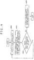
- the above-mentioned diagnostic process in the time series data primary diagnostic unit 121 is executed in a flow shown in Fig. 4 .
- the time series data primary diagnostic unit 121 inputs time series data showing values of the pressure sensor (step s601) and reads reference value information corresponding to the input time series data in reference value information held in the time series data primary diagnostic unit 121 beforehand (step s602).
- the time series data primary diagnostic unit reads a reference value PT corresponding to the value of the pressure sensor.
- the time series data primary diagnostic unit 121 compares the input time series data showing values of the pressure sensor and the reference value PT and determines whether the time series data is equal to or exceeds the reference value PT or not (step s603).
- the time series data primary diagnostic unit determines the equipment as normal, processing is returned to the step s601, and the processing is continued.
- the time series data primary diagnostic unit determines the condition of the equipment as abnormal and outputs a result of the determination as abnormal and abnormality occurrence time (in this case, the time D11) to the time series data management unit 123 as a primary diagnostic result (step s604).
- the diagnostic device on the server side 3 receives the primary diagnostic result and the time series data respectively transmitted from the diagnostic device on the machine side 2 and makes diagnosis using the time series data which the time series data secondary diagnostic unit 131 receives.
- a result of the diagnosis by the time series data secondary diagnostic unit 131 (hereinafter called as a secondary diagnostic result) is output to the diagnostic result display device 132 and the diagnostic result comparing unit 133 together with the primary diagnostic result transmitted from the diagnostic device on the machine side 2.
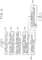
- a diagnostic process executed by the time series data secondary diagnostic unit 131 is executed in a flow shown in Fig. 5 .
- the time series data secondary diagnostic unit 131 receives time series data from the time series data management unit 123 (step s701) and calculates a mean value ⁇ and standard deviation ⁇ respectively of the input time series data (step s702) .
- a method of regarding a point of time at which time series data showing normalized values and exceeding ⁇ 3 continuously emerges and a frequency of continuation reaches a reference frequency as abnormality occurrence time and others are used for the determination of abnormality occurrence time.
- a result of the determination as abnormal is acquired by the above-mentioned method and abnormality occurrence time is determined as D14 as shown in Fig. 3 .
- the time series data secondary diagnostic unit 131 outputs the abnormality determination result and the abnormality occurrence time D14 to the diagnostic result display device 132 and the diagnostic result comparing unit 133 as a secondary diagnostic result together with the primary diagnostic result received from the time series data management unit 123.
- the diagnostic result comparing unit 133 compares the primary diagnostic result and the secondary diagnostic result respectively received from the time series data secondary diagnostic unit 131 and determines whether the abnormality determination results are coincident or not and whether the abnormality occurrence time is coincident or not. The coincidence of the abnormality occurrence time is determined depending upon whether difference in occurrence time is within a predetermined period or not.
- the diagnostic result comparing unit 133 outputs a result of the comparison to the diagnostic result display device 132.
- the diagnostic result comparing unit 133 reads the time series data from the time D12 to the time D14 from the time series data secondary diagnostic unit 131, calculates a lower limit value of the data as a new reference value Pa, outputs this to the diagnostic setting updating unit 134 as diagnostic setting change instruction information, and the diagnostic setting updating unit 134 transmits the diagnostic setting change instruction information to the time series data primary diagnostic unit 121.
- the time series data primary diagnostic unit 121 sets the reference value Pa included in the received diagnostic setting change instruction information as a new reference value.
- the time series data primary diagnostic unit 121 executes a diagnostic procedure of the diagnostic device on the machine side 2 and the diagnostic procedure may be also repeated until the primary diagnostic result and the secondary diagnostic result are coincident in a process executed in the diagnostic result comparing unit 133 of the diagnostic device on the server side 3 for comparing the primary and secondary diagnostic results.
- the diagnostic result comparing unit 133 outputs the diagnostic setting change instruction information to the diagnostic result display device 132.
- the diagnostic result display device 132 displays each information output by the time series data secondary diagnostic unit 131 and the diagnostic result comparing unit 133 on a monitor (not shown) and presents each information to a user, for example, a manager (not shown).
- Fig. 9 shows an example of the display of the primary diagnostic result (the first diagnostic result) and the secondary diagnostic result (the second diagnostic result) respectively output by the time series data secondary diagnostic unit 131.
- the diagnostic result display device 132 displays the secondary diagnostic result together with the primary diagnostic result.
- Fig. 10 shows an example of the display of a result of comparison between the primary diagnostic result and the secondary diagnostic result respectively output by the diagnostic result comparing unit 133.
- the diagnostic result display device 132 displays difference in pressure between the reference values for determination and difference in the number of days between abnormality detection dates as the information of comparison between the primary diagnostic result and the secondary diagnostic result.
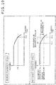
- FIG. 11 shows an example of the display of diagnostic setting change instruction information output by the diagnostic result comparing unit 133.
- the diagnostic result display device 132 displays that the reference value for determining a value of the sensor is changed from PT to Pa. It is desirable that the diagnostic setting change instruction information is displayed together with the result of comparing the primary diagnostic result and the secondary diagnostic result shown in Fig. 10 .
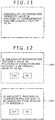
- Fig. 12 shows an example of display when the manager instructs to allow a change of the diagnostic process
- a screen 1101 shows an example of display for allowing a change of the reference value for determination
- a screen 1102 shows an example of display for allowing rewriting the whole diagnostic program.
- the diagnostic result comparing unit 133 outputs diagnostic setting change instruction information via the diagnostic setting updating unit 134
- the manager can verify a change of setting by displaying the screen 1101 before the output and the reliability of setting update is enhanced.
- the whole diagnostic program may be also rewritten, in that case, the manager can also verify a change of the diagnostic program by displaying the screen 1102 before the output, and the reliability of the update of the diagnostic program is enhanced.
- the abnormality diagnostic system 1 is configured by the diagnostic device on the machine side 2 and the diagnostic device on the server side 3 and is multiplexed, diagnostic precision can be enhanced even if the computer arranged on the machine side does not have sufficient throughput.
- the diagnostic device on the machine side 2 extracts time series data related to the first diagnostic result and outputs it to the diagnostic device on the server side 3, communication data volume decreases and communication capacity can be reduced.
- the primary diagnostic result and the secondary diagnostic result in addition to them are displayed on the diagnostic result display device 132 and further, the update information of diagnostic setting information is displayed there, the verification by a person of the diagnostic results and an updated state of diagnostic information is enabled.
- a cause of abnormality is estimated by using the primary diagnostic result for reference information, the necessity or the timing of maintenance and repair and further, preventive maintenance measures can be examined, and reliable maintenance management and reliable preventive maintenance can be performed.
- the diagnostic precision can be further enhanced by monitoring the temporal transition of the primary diagnostic result and the secondary diagnostic result, enabling judging whether diagnostic algorithm used by the time series data primary diagnostic unit 121 and the time series data secondary diagnostic unit 131 is proper for diagnosis or not, improving the algorithm itself when the diagnostic algorithm is not proper and enabling making more proper diagnosis (refer to a second embodiment).
- the diagnostic setting information of the time series data primary diagnostic unit 121 can be automatically updated when the time series data secondary diagnostic unit 131 updates the diagnostic setting information of the time series data primary diagnostic unit 121 based upon a result of comparison between the primary diagnostic result and the secondary diagnostic result, the diagnostic precision can be also enhanced in this way.
- FIG. 7 A second embodiment of the present invention will be described using Figs. 7 , 1 , 2 and 4 below.
- a function and operation of the abnormality diagnostic system 1 according to the present invention and shown in Figs. 1 and 2 are the same as the contents in the first embodiment, the description of them is omitted.
- Fig. 7 shows time series data 401 of values of a pressure sensor and time series data 402 of signals showing an active state of equipment, which are data acquired by digitizing signals which an abnormality diagnostic system 1 receives from a sensor attached to the equipment (not shown) to be diagnosed.
- Fig. 7 shows a situation in which the values of the pressure sensor also vary according to activation and a stop, repeating the activation and the stop according to the elapse of time. In this embodiment, a situation in which an abnormality occurs in the equipment in the vicinity of time D24 and values of the pressure sensor gradually fall because of the abnormality is described.
- a time series data primary diagnostic unit 121 receives time series data showing values of the pressure sensor and executes a diagnostic process .
- the abnormality of the equipment is notified a time series data management unit 123.
- the normality of the equipment is notified the time series data management unit 123.
- the above-mentioned diagnostic process in the time series data primary diagnostic unit 121 is executed in the flow shown in Fig. 4 as in the first embodiment.
- the time series data primary diagnostic unit 121 inputs time series data showing values of the pressure sensor (the step s601) and reads reference value information corresponding to the input time series data in reference value information held in the time series data primary diagnostic unit 121 beforehand (the step s602).
- the reference value PT corresponding to the value of the pressure sensor is read.
- the time series data primary diagnostic unit 121 compares the input time series data showing the values of the pressure sensor and the reference value PT and determines whether the time series data is equal to or exceeds the reference value PT or not (the step s603).
- the time series data management unit 123 it is regarded as a normal condition that the time series data is equal to or exceeds the reference value, however, depending upon a signal of the sensor, the reference value is different and in addition, a normal range is also different.
- a condition of the equipment is determined as normal, processing is returned to the step s601, and the processing is continued.
- the input time series data showing the values of the pressure sensor is below the reference value PT, a condition of the equipment is determined as abnormal, and an abnormality determination result and abnormality occurrence time (in this case, the time D21) are output to the time series data management unit 123 as a primary diagnostic result (the step s604).
- the determination as abnormal converts to the determination as normal.
- abnormality once detected converts to normality depending upon timing at which the diagnostic device on the machine side 2 notifies a diagnostic device on the server side 3
- a situation in which a diagnostic result that an abnormality occurs is not notified the diagnostic device on the server side 3 may occur as a result.
- a situation in which abnormality and normality are repeatedly notified although an abnormality actually continues may occur.
- time D24 that an abnormality actually occurs when the diagnostic device on the machine side 2 notifies the diagnostic device on the server side 3 that the equipment is abnormal, it is known that time at which the abnormality is detected rather lags.
- abnormality and abnormality cannot be also correctly detected by a diagnostic process using normalizing processing of time series data which a time series data secondary diagnostic unit 131 of the diagnostic device on the server side 3 executes as in the first embodiment.
- a diagnostic process using the normalizing processing as a reference value is set to Pb, abnormality can be detected at time D23, however, at time D25, the abnormality is determined as a normal condition again by mistake, and although the abnormality continues, the abnormality is not correctly determined.
- a manager on the server side can grasp the above-mentioned diagnostic situation based upon information displayed on a diagnostic result display device 132.
- the manager on the server side rewrites the diagnostic process (a diagnostic program or diagnostic algorithm) by the time series data primary diagnostic unit 121 of the diagnostic device on the machine side 2 and the time series data secondary diagnostic unit 131 of the diagnostic device on the server side 3 so that the abnormal fall of a pressure value is detected after the time series data secondary diagnostic unit 131 of the diagnostic device on the server side 3 is improved and both the signal 401 showing the pressure value and the signal 402 showing an active state are added.
- the diagnostic process a diagnostic program or diagnostic algorithm
- the time series data 402 of signals showing an active state of the equipment is input in addition to the time series data 401 showing values of the pressure sensor, and the manager on the server side rewrites the diagnostic process so that determination is made using the reference value Pb in a stopped state and using a reference value Pc in the active state.
- the above-mentioned abnormality is ordinarily correctly determined as abnormality since the time D24 by changing as described above.
- the time series data management unit 123 of the diagnostic device on the machine side 2 outputs the time series data 402 of signals showing the active state of the equipment in addition to the time series data 401 showing values of the pressure sensor to the diagnostic device on the server side 3 together with the primary diagnostic result.
- the diagnostic process is rewritten so that in the diagnostic process by the time series data secondary diagnostic unit 131, a normalized value of time series data in the stopped state and a normalized value of that in the active state are separately calculated, it is determined based upon the respective normalized values whether abnormality occurs or not, and when it is determined that abnormality occurs in both states, the equipment is determined as abnormal.
- the rewrite of the diagnostic process (the diagnostic algorithm) by the time series data primary diagnostic unit 121 of the diagnostic device on the machine side 2 may be also directly performed in the diagnostic device on the machine side 2, however, in this embodiment, a diagnostic setting updating unit 134 of the diagnostic device on the server side 3 performs the rewrite. In that case, it is not only a new reference value but the information of a new diagnostic process itself that determination is made using plural signals and reference values that the diagnostic setting updating unit 134 transmits to the time series data primary diagnostic unit 121. As not only the new set values but the new diagnostic process can be used because the time series data primary diagnostic unit 121 has means to update itself as described above, diagnostic precision on the equipment side can be further enhanced.
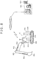
- Fig. 8 shows the whole configuration of a large hydraulic shovel that is one example of industrial machinery to which the abnormality diagnostic system according to the present invention is applied and an abnormality diagnostic system.
- the large hydraulic shovel 8 can perform operation such as excavation by provided each operating mechanism.
- a bucket 801, an arm 802 and a boom 803 configure an operating machine and these are driven by hydraulic cylinders 811, 812, 813.
- a revolving superstructure 806, a revolving mechanism 804 that revolves the revolving superstructure 806 and right and left crawlers (crawler belts) 805 (only one side is shown) as a running mechanism of the whole hydraulic shovel are provided.
- the revolving mechanism 804 is provided with a hydraulic motor for revolving (not shown) and the crawler 805 is respectively provided with a hydraulic motor for running.
- the revolving superstructure 806 is equipped with two engines 820 (only one is shown) for example and plural main pumps 821 (only one is shown) driven by these engines 820.
- a hydraulic actuator such as the hydraulic cylinders 811, 812, 813 and the hydraulic motor is driven by oil discharged from the main pump 821.
- a vehicle body controller 830 for controlling each operating mechanism, collecting and monitoring information from a sensor is mounted.
- the vehicle body controller 830 has communication facility and communicates with a server 831.
- the server 831 is installed in a management office 832 (for example, an office of a maker, a sales shop and a dealer and rental service of the hydraulic shovel 1).
- a diagnostic device on the machine side 2 that configures the abnormality diagnostic system 1 according to the present invention is built in the vehicle body controller 830 and a diagnostic device on the server side 3 is built in the server 831.
- the abnormality diagnostic system 1 diagnoses the main pump 821 for example, a pressure sensor (not shown) that detects discharge pressure is attached to the respective main pumps 821, and the diagnostic device on the machine side 2 receives signals output by the pressure sensors as time series data.
- the diagnostic device on the machine side 2 receives time series data from the sensor every pump and processes every pump.
- the diagnostic device on the server side 3 also similarly receives the time series data output from the diagnostic device on the machine side 2 every pump and processes every pump.
- the abnormality diagnostic system 1 may also diagnose the engine 820 and another equipment.
Landscapes
- Engineering & Computer Science (AREA)
- Physics & Mathematics (AREA)
- General Physics & Mathematics (AREA)
- Automation & Control Theory (AREA)
- Theoretical Computer Science (AREA)
- Human Computer Interaction (AREA)
- Quality & Reliability (AREA)
- General Engineering & Computer Science (AREA)
- Testing And Monitoring For Control Systems (AREA)
Applications Claiming Priority (2)
| Application Number | Priority Date | Filing Date | Title |
|---|---|---|---|
| JP2010242180A JP5455866B2 (ja) | 2010-10-28 | 2010-10-28 | 異常診断装置および産業機械 |
| PCT/JP2011/074218 WO2012057001A1 (ja) | 2010-10-28 | 2011-10-20 | 異常診断装置および産業機械 |
Publications (3)
| Publication Number | Publication Date |
|---|---|
| EP2634660A1 EP2634660A1 (en) | 2013-09-04 |
| EP2634660A4 EP2634660A4 (en) | 2016-04-13 |
| EP2634660B1 true EP2634660B1 (en) | 2017-12-27 |
Family
ID=45993713
Family Applications (1)
| Application Number | Title | Priority Date | Filing Date |
|---|---|---|---|
| EP11836137.7A Active EP2634660B1 (en) | 2010-10-28 | 2011-10-20 | Anomaly diagnostic device and industrial machine |
Country Status (5)
| Country | Link |
|---|---|
| US (1) | US9678845B2 (enExample) |
| EP (1) | EP2634660B1 (enExample) |
| JP (1) | JP5455866B2 (enExample) |
| CN (1) | CN103180793B (enExample) |
| WO (1) | WO2012057001A1 (enExample) |
Cited By (1)
| Publication number | Priority date | Publication date | Assignee | Title |
|---|---|---|---|---|
| EP4283426A4 (en) * | 2021-01-25 | 2024-12-18 | The Japan Steel Works, Ltd. | Abnormality detection system, molding equipment system, abnormality detection device, abnormality detection method, and computer program |
Families Citing this family (30)
| Publication number | Priority date | Publication date | Assignee | Title |
|---|---|---|---|---|
| JP5988740B2 (ja) * | 2012-07-13 | 2016-09-07 | 日立建機株式会社 | 稼働機械の保守管理装置 |
| JP5836222B2 (ja) * | 2012-08-14 | 2015-12-24 | 日立オートモティブシステムズ株式会社 | 車両制御装置および車両制御システム |
| JP5914382B2 (ja) * | 2013-02-20 | 2016-05-11 | 日立建機株式会社 | 状態監視システム、状態監視装置、および端末装置 |
| JP6060261B2 (ja) * | 2013-06-24 | 2017-01-11 | 株式会社日立製作所 | 状態監視装置 |
| JP2015084176A (ja) * | 2013-10-25 | 2015-04-30 | 日立建機株式会社 | 故障診断装置および稼働機械 |
| EP2887236A1 (en) * | 2013-12-23 | 2015-06-24 | D square N.V. | System and method for similarity search in process data |
| JP5863763B2 (ja) | 2013-12-27 | 2016-02-17 | 三菱重工業株式会社 | 油圧機械の診断方法及び診断装置 |
| JP6215446B2 (ja) * | 2014-03-03 | 2017-10-18 | 株式会社日立製作所 | 機械の材料疲労の表示方法、及びその装置 |
| JP6445859B2 (ja) * | 2014-12-16 | 2018-12-26 | 株式会社東芝 | プラント監視装置 |
| FR3041326B1 (fr) * | 2015-09-18 | 2019-05-10 | Safran Aircraft Engines | Systeme et procede d'aide a la decision pour la maintenance d'une machine avec apprentissage d'un modele de decision supervise par avis d'experts |
| EP3508833B1 (en) * | 2016-09-02 | 2024-07-17 | Hitachi, Ltd. | Diagnostic device, diagnostic method, and diagnostic program |
| US10430021B2 (en) * | 2016-10-05 | 2019-10-01 | Snap-On Incorporated | System and method for providing an interactive vehicle diagnostic display |
| JP6842299B2 (ja) * | 2016-12-28 | 2021-03-17 | 三菱パワー株式会社 | 診断装置、診断方法及びプログラム |
| WO2018135171A1 (ja) * | 2017-01-19 | 2018-07-26 | 株式会社日立製作所 | 保全管理システム及びそれに用いる保全管理確認装置 |
| US11397655B2 (en) * | 2017-02-24 | 2022-07-26 | Hitachi, Ltd. | Abnormality diagnosis system that reconfigures a diagnostic program based on an optimal diagnosis procedure found by comparing a plurality of diagnosis procedures |
| JP6829158B2 (ja) * | 2017-07-18 | 2021-02-10 | 株式会社東芝 | データ処理装置、データ処理方法、およびプログラム |
| CN110096036A (zh) * | 2018-01-29 | 2019-08-06 | 阿里巴巴集团控股有限公司 | 一种设备状态的确定方法、装置及设备 |
| JP7074489B2 (ja) | 2018-02-08 | 2022-05-24 | 株式会社Screenホールディングス | データ処理方法、データ処理装置、および、データ処理プログラム |
| JP7186518B2 (ja) * | 2018-06-05 | 2022-12-09 | 株式会社東芝 | 異常診断装置、異常診断システムおよび異常診断方法 |
| CN112334924A (zh) * | 2018-07-10 | 2021-02-05 | 住友重机械工业株式会社 | 施工机械的显示方法及施工机械的支持装置 |
| US11093314B2 (en) * | 2018-07-23 | 2021-08-17 | Mitsubishi Electric Corporation | Time-sequential data diagnosis device, additional learning method, and recording medium |
| DE102018121270B4 (de) | 2018-08-31 | 2023-12-21 | Volkswagen Aktiengesellschaft | Diagnoseverfahren, Diagnosesystem und Kraftfahrzeug |
| CN111340250A (zh) * | 2018-12-19 | 2020-06-26 | 富泰华工业(深圳)有限公司 | 设备检修装置、方法及计算机可读存储介质 |
| DE102019219727A1 (de) | 2018-12-26 | 2020-07-02 | Presenso Ltd. | System und Verfahren zum Detektieren von Anomalien in Sensordaten von industriellen Maschinen, die in einer vorbestimmten Umgebung angeordnet sind |
| US11527987B2 (en) * | 2018-12-27 | 2022-12-13 | Mitsubishi Electric Corporation | Abnormality diagnosis device and abnormality diagnosis method |
| JP7357450B2 (ja) * | 2019-02-28 | 2023-10-06 | コマツ産機株式会社 | 学習データを収集するためのシステム、及び方法 |
| CN112988501B (zh) * | 2019-12-17 | 2023-02-03 | 深信服科技股份有限公司 | 一种告警信息生成方法、装置、电子设备及存储介质 |
| KR102340395B1 (ko) * | 2020-01-02 | 2021-12-15 | 두산중공업 주식회사 | 플랜트의 고장을 진단하기 위한 장치 및 이를 위한 방법 |
| JP7489615B2 (ja) * | 2020-09-29 | 2024-05-24 | パナソニックIpマネジメント株式会社 | 診断システム、診断方法及びプログラム |
| JP7575298B2 (ja) * | 2021-02-26 | 2024-10-29 | 株式会社小松製作所 | 作業機械の診断支援システム、作業機械の故障診断システム、作業機械の診断支援方法および作業機械の故障診断方法 |
Family Cites Families (14)
| Publication number | Priority date | Publication date | Assignee | Title |
|---|---|---|---|---|
| US4258421A (en) * | 1978-02-27 | 1981-03-24 | Rockwell International Corporation | Vehicle monitoring and recording system |
| JP2000210800A (ja) * | 1999-01-27 | 2000-08-02 | Komatsu Ltd | 産業機械のモニタ方法およびその装置 |
| DE50108313D1 (de) * | 2000-03-09 | 2006-01-12 | Continental Teves Ag & Co Ohg | Anordnung und vorrichtung zur erfassung von gierbewegungen mittels redundanter messkanäle |
| JP3612472B2 (ja) * | 2000-06-22 | 2005-01-19 | 株式会社日立製作所 | 遠隔監視診断システム、及び遠隔監視診断方法 |
| KR100523228B1 (ko) * | 2001-05-08 | 2005-10-20 | 히다치 겡키 가부시키 가이샤 | 작업기계, 작업기계의 고장진단시스템, 작업기계의메인티넌스시스템 |
| JP2003015734A (ja) | 2001-07-02 | 2003-01-17 | Toshiba Corp | 時系列データ圧縮方法および時系列データ格納装置およびプログラム |
| JP4306349B2 (ja) | 2003-07-25 | 2009-07-29 | 株式会社日立製作所 | 車両情報端末装置 |
| DE102005005995A1 (de) * | 2004-02-23 | 2006-06-22 | Continental Teves Ag & Co. Ohg | Verfahren und Vorrichtung zum Überwachen von Signalverarbeitungseinheiten für Sensoren |
| EP1850229B1 (de) * | 2006-04-28 | 2012-10-10 | Marquardt GmbH | Vorrichtung und Verfahren zur Überwachung einer Funktionseinheit in einem Fahrzeug |
| JP2008097363A (ja) * | 2006-10-12 | 2008-04-24 | Okuma Corp | 異常診断方法及びその装置 |
| JP5072373B2 (ja) * | 2007-01-16 | 2012-11-14 | 株式会社東芝 | 遠隔監視・診断システム |
| WO2009020229A1 (ja) * | 2007-08-09 | 2009-02-12 | Hitachi Construction Machinery Co., Ltd. | 作業機械の機器診断装置及び機器診断システム |
| JP5198087B2 (ja) | 2008-02-21 | 2013-05-15 | 富士フイルム株式会社 | 製造設備の診断装置及び方法 |
| JP4876136B2 (ja) * | 2009-02-17 | 2012-02-15 | 株式会社日立製作所 | 異常診断装置および異常診断方法 |
-
2010
- 2010-10-28 JP JP2010242180A patent/JP5455866B2/ja active Active
-
2011
- 2011-10-20 WO PCT/JP2011/074218 patent/WO2012057001A1/ja not_active Ceased
- 2011-10-20 CN CN201180052092.2A patent/CN103180793B/zh active Active
- 2011-10-20 EP EP11836137.7A patent/EP2634660B1/en active Active
- 2011-10-20 US US13/881,543 patent/US9678845B2/en active Active
Non-Patent Citations (1)
| Title |
|---|
| None * |
Cited By (1)
| Publication number | Priority date | Publication date | Assignee | Title |
|---|---|---|---|---|
| EP4283426A4 (en) * | 2021-01-25 | 2024-12-18 | The Japan Steel Works, Ltd. | Abnormality detection system, molding equipment system, abnormality detection device, abnormality detection method, and computer program |
Also Published As
| Publication number | Publication date |
|---|---|
| US9678845B2 (en) | 2017-06-13 |
| US20130218522A1 (en) | 2013-08-22 |
| JP5455866B2 (ja) | 2014-03-26 |
| CN103180793A (zh) | 2013-06-26 |
| CN103180793B (zh) | 2016-01-20 |
| WO2012057001A1 (ja) | 2012-05-03 |
| JP2012094044A (ja) | 2012-05-17 |
| EP2634660A4 (en) | 2016-04-13 |
| EP2634660A1 (en) | 2013-09-04 |
Similar Documents
| Publication | Publication Date | Title |
|---|---|---|
| EP2634660B1 (en) | Anomaly diagnostic device and industrial machine | |
| CN109001649B (zh) | 一种电源智能诊断系统及保护方法 | |
| JP2012094044A5 (enExample) | ||
| CN111435557B (zh) | 用于检测机器部件问题的故障检测装置 | |
| EP3767406B1 (en) | Controller area network and connectivity health troubleshooting system | |
| US10113552B2 (en) | System, method, and apparatus to monitor compressor health | |
| AU2013245998B2 (en) | Efficient health management, diagnosis and prognosis of a machine | |
| US20050134284A1 (en) | Control system health test system and method | |
| CN110582626B (zh) | 用由磨损因子校正的异常检测来监视涡轮机的系统和方法 | |
| EP3159519A2 (en) | Variable geometry turbocharger prognostics | |
| JP2008196428A (ja) | 機体診断方法および機体診断システム | |
| CN110067278A (zh) | 挖土机、挖土机管理装置及挖土机信息系统 | |
| WO2017083141A1 (en) | Electric submersible pump health assessment | |
| CN107291475B (zh) | 通用型phm应用配置方法和装置 | |
| CN111598346A (zh) | 故障检测方法、装置、检测设备、旋挖机及存储介质 | |
| US20210048792A1 (en) | Diagnostic apparatus, system, diagnostic method, and program | |
| JP5485441B2 (ja) | 異常診断装置および産業機械 | |
| JP2021179988A (ja) | 機械構成要素のリアルタイム稼働状態監視のためのシステムおよび方法 | |
| EP2026159A2 (en) | A method and system for automatically evaluating the performance of a power plant machine | |
| CN118468169A (zh) | 基于物联网的设备故障监测方法、装置、设备及存储介质 | |
| JP2015084176A (ja) | 故障診断装置および稼働機械 | |
| CN119394675B (zh) | 空气悬架故障诊断方法、装置、设备及可读存储介质 | |
| CN119573984B (zh) | 液压支架的泄漏诊断系统及方法 | |
| KR101490471B1 (ko) | 신호 계측 및 진단 시스템과 그 방법 | |
| KR101983390B1 (ko) | 휠 타입 굴삭기의 주행계통의 이상 진단 방법 및 장치 |
Legal Events
| Date | Code | Title | Description |
|---|---|---|---|
| PUAI | Public reference made under article 153(3) epc to a published international application that has entered the european phase |
Free format text: ORIGINAL CODE: 0009012 |
|
| 17P | Request for examination filed |
Effective date: 20130528 |
|
| AK | Designated contracting states |
Kind code of ref document: A1 Designated state(s): AL AT BE BG CH CY CZ DE DK EE ES FI FR GB GR HR HU IE IS IT LI LT LU LV MC MK MT NL NO PL PT RO RS SE SI SK SM TR |
|
| DAX | Request for extension of the european patent (deleted) | ||
| RA4 | Supplementary search report drawn up and despatched (corrected) |
Effective date: 20160315 |
|
| RIC1 | Information provided on ipc code assigned before grant |
Ipc: G07C 5/00 20060101ALN20160309BHEP Ipc: G07C 3/00 20060101ALN20160309BHEP Ipc: G06F 11/30 20060101ALI20160309BHEP Ipc: G05B 23/02 20060101AFI20160309BHEP Ipc: G07C 5/08 20060101ALN20160309BHEP |
|
| GRAP | Despatch of communication of intention to grant a patent |
Free format text: ORIGINAL CODE: EPIDOSNIGR1 |
|
| STAA | Information on the status of an ep patent application or granted ep patent |
Free format text: STATUS: GRANT OF PATENT IS INTENDED |
|
| RIC1 | Information provided on ipc code assigned before grant |
Ipc: G07C 5/00 20060101ALN20170918BHEP Ipc: G07C 5/08 20060101ALN20170918BHEP Ipc: G05B 23/02 20060101AFI20170918BHEP Ipc: G07C 3/00 20060101ALN20170918BHEP Ipc: G06F 11/30 20060101ALI20170918BHEP |
|
| INTG | Intention to grant announced |
Effective date: 20171009 |
|
| RIN1 | Information on inventor provided before grant (corrected) |
Inventor name: SUZUKI, HIDEAKI Inventor name: UCHIYAMA, HIROKI Inventor name: YUDA, SHINYA Inventor name: NAKAMURA, KOZO |
|
| GRAS | Grant fee paid |
Free format text: ORIGINAL CODE: EPIDOSNIGR3 |
|
| GRAA | (expected) grant |
Free format text: ORIGINAL CODE: 0009210 |
|
| STAA | Information on the status of an ep patent application or granted ep patent |
Free format text: STATUS: THE PATENT HAS BEEN GRANTED |
|
| AK | Designated contracting states |
Kind code of ref document: B1 Designated state(s): AL AT BE BG CH CY CZ DE DK EE ES FI FR GB GR HR HU IE IS IT LI LT LU LV MC MK MT NL NO PL PT RO RS SE SI SK SM TR |
|
| REG | Reference to a national code |
Ref country code: GB Ref legal event code: FG4D |
|
| REG | Reference to a national code |
Ref country code: CH Ref legal event code: EP |
|
| REG | Reference to a national code |
Ref country code: AT Ref legal event code: REF Ref document number: 958810 Country of ref document: AT Kind code of ref document: T Effective date: 20180115 |
|
| REG | Reference to a national code |
Ref country code: IE Ref legal event code: FG4D |
|
| REG | Reference to a national code |
Ref country code: DE Ref legal event code: R096 Ref document number: 602011044616 Country of ref document: DE |
|
| REG | Reference to a national code |
Ref country code: NL Ref legal event code: FP |
|
| PG25 | Lapsed in a contracting state [announced via postgrant information from national office to epo] |
Ref country code: LT Free format text: LAPSE BECAUSE OF FAILURE TO SUBMIT A TRANSLATION OF THE DESCRIPTION OR TO PAY THE FEE WITHIN THE PRESCRIBED TIME-LIMIT Effective date: 20171227 Ref country code: NO Free format text: LAPSE BECAUSE OF FAILURE TO SUBMIT A TRANSLATION OF THE DESCRIPTION OR TO PAY THE FEE WITHIN THE PRESCRIBED TIME-LIMIT Effective date: 20180327 Ref country code: FI Free format text: LAPSE BECAUSE OF FAILURE TO SUBMIT A TRANSLATION OF THE DESCRIPTION OR TO PAY THE FEE WITHIN THE PRESCRIBED TIME-LIMIT Effective date: 20171227 |
|
| REG | Reference to a national code |
Ref country code: LT Ref legal event code: MG4D |
|
| REG | Reference to a national code |
Ref country code: AT Ref legal event code: MK05 Ref document number: 958810 Country of ref document: AT Kind code of ref document: T Effective date: 20171227 |
|
| PG25 | Lapsed in a contracting state [announced via postgrant information from national office to epo] |
Ref country code: BG Free format text: LAPSE BECAUSE OF FAILURE TO SUBMIT A TRANSLATION OF THE DESCRIPTION OR TO PAY THE FEE WITHIN THE PRESCRIBED TIME-LIMIT Effective date: 20180327 Ref country code: LV Free format text: LAPSE BECAUSE OF FAILURE TO SUBMIT A TRANSLATION OF THE DESCRIPTION OR TO PAY THE FEE WITHIN THE PRESCRIBED TIME-LIMIT Effective date: 20171227 Ref country code: RS Free format text: LAPSE BECAUSE OF FAILURE TO SUBMIT A TRANSLATION OF THE DESCRIPTION OR TO PAY THE FEE WITHIN THE PRESCRIBED TIME-LIMIT Effective date: 20171227 Ref country code: HR Free format text: LAPSE BECAUSE OF FAILURE TO SUBMIT A TRANSLATION OF THE DESCRIPTION OR TO PAY THE FEE WITHIN THE PRESCRIBED TIME-LIMIT Effective date: 20171227 Ref country code: GR Free format text: LAPSE BECAUSE OF FAILURE TO SUBMIT A TRANSLATION OF THE DESCRIPTION OR TO PAY THE FEE WITHIN THE PRESCRIBED TIME-LIMIT Effective date: 20180328 |
|
| PG25 | Lapsed in a contracting state [announced via postgrant information from national office to epo] |
Ref country code: SK Free format text: LAPSE BECAUSE OF FAILURE TO SUBMIT A TRANSLATION OF THE DESCRIPTION OR TO PAY THE FEE WITHIN THE PRESCRIBED TIME-LIMIT Effective date: 20171227 Ref country code: CZ Free format text: LAPSE BECAUSE OF FAILURE TO SUBMIT A TRANSLATION OF THE DESCRIPTION OR TO PAY THE FEE WITHIN THE PRESCRIBED TIME-LIMIT Effective date: 20171227 Ref country code: EE Free format text: LAPSE BECAUSE OF FAILURE TO SUBMIT A TRANSLATION OF THE DESCRIPTION OR TO PAY THE FEE WITHIN THE PRESCRIBED TIME-LIMIT Effective date: 20171227 Ref country code: CY Free format text: LAPSE BECAUSE OF FAILURE TO SUBMIT A TRANSLATION OF THE DESCRIPTION OR TO PAY THE FEE WITHIN THE PRESCRIBED TIME-LIMIT Effective date: 20171227 Ref country code: ES Free format text: LAPSE BECAUSE OF FAILURE TO SUBMIT A TRANSLATION OF THE DESCRIPTION OR TO PAY THE FEE WITHIN THE PRESCRIBED TIME-LIMIT Effective date: 20171227 |
|
| PG25 | Lapsed in a contracting state [announced via postgrant information from national office to epo] |
Ref country code: IS Free format text: LAPSE BECAUSE OF FAILURE TO SUBMIT A TRANSLATION OF THE DESCRIPTION OR TO PAY THE FEE WITHIN THE PRESCRIBED TIME-LIMIT Effective date: 20180427 Ref country code: RO Free format text: LAPSE BECAUSE OF FAILURE TO SUBMIT A TRANSLATION OF THE DESCRIPTION OR TO PAY THE FEE WITHIN THE PRESCRIBED TIME-LIMIT Effective date: 20171227 Ref country code: SM Free format text: LAPSE BECAUSE OF FAILURE TO SUBMIT A TRANSLATION OF THE DESCRIPTION OR TO PAY THE FEE WITHIN THE PRESCRIBED TIME-LIMIT Effective date: 20171227 Ref country code: AT Free format text: LAPSE BECAUSE OF FAILURE TO SUBMIT A TRANSLATION OF THE DESCRIPTION OR TO PAY THE FEE WITHIN THE PRESCRIBED TIME-LIMIT Effective date: 20171227 Ref country code: PL Free format text: LAPSE BECAUSE OF FAILURE TO SUBMIT A TRANSLATION OF THE DESCRIPTION OR TO PAY THE FEE WITHIN THE PRESCRIBED TIME-LIMIT Effective date: 20171227 |
|
| REG | Reference to a national code |
Ref country code: DE Ref legal event code: R097 Ref document number: 602011044616 Country of ref document: DE |
|
| PLBE | No opposition filed within time limit |
Free format text: ORIGINAL CODE: 0009261 |
|
| STAA | Information on the status of an ep patent application or granted ep patent |
Free format text: STATUS: NO OPPOSITION FILED WITHIN TIME LIMIT |
|
| PG25 | Lapsed in a contracting state [announced via postgrant information from national office to epo] |
Ref country code: DK Free format text: LAPSE BECAUSE OF FAILURE TO SUBMIT A TRANSLATION OF THE DESCRIPTION OR TO PAY THE FEE WITHIN THE PRESCRIBED TIME-LIMIT Effective date: 20171227 |
|
| 26N | No opposition filed |
Effective date: 20180928 |
|
| PG25 | Lapsed in a contracting state [announced via postgrant information from national office to epo] |
Ref country code: SI Free format text: LAPSE BECAUSE OF FAILURE TO SUBMIT A TRANSLATION OF THE DESCRIPTION OR TO PAY THE FEE WITHIN THE PRESCRIBED TIME-LIMIT Effective date: 20171227 |
|
| REG | Reference to a national code |
Ref country code: CH Ref legal event code: PL |
|
| REG | Reference to a national code |
Ref country code: BE Ref legal event code: MM Effective date: 20181031 |
|
| PG25 | Lapsed in a contracting state [announced via postgrant information from national office to epo] |
Ref country code: LU Free format text: LAPSE BECAUSE OF NON-PAYMENT OF DUE FEES Effective date: 20181020 Ref country code: MC Free format text: LAPSE BECAUSE OF FAILURE TO SUBMIT A TRANSLATION OF THE DESCRIPTION OR TO PAY THE FEE WITHIN THE PRESCRIBED TIME-LIMIT Effective date: 20171227 |
|
| REG | Reference to a national code |
Ref country code: IE Ref legal event code: MM4A |
|
| PG25 | Lapsed in a contracting state [announced via postgrant information from national office to epo] |
Ref country code: BE Free format text: LAPSE BECAUSE OF NON-PAYMENT OF DUE FEES Effective date: 20181031 Ref country code: CH Free format text: LAPSE BECAUSE OF NON-PAYMENT OF DUE FEES Effective date: 20181031 Ref country code: LI Free format text: LAPSE BECAUSE OF NON-PAYMENT OF DUE FEES Effective date: 20181031 Ref country code: FR Free format text: LAPSE BECAUSE OF NON-PAYMENT OF DUE FEES Effective date: 20181031 |
|
| PG25 | Lapsed in a contracting state [announced via postgrant information from national office to epo] |
Ref country code: IE Free format text: LAPSE BECAUSE OF NON-PAYMENT OF DUE FEES Effective date: 20181020 |
|
| PG25 | Lapsed in a contracting state [announced via postgrant information from national office to epo] |
Ref country code: MT Free format text: LAPSE BECAUSE OF NON-PAYMENT OF DUE FEES Effective date: 20181020 |
|
| PG25 | Lapsed in a contracting state [announced via postgrant information from national office to epo] |
Ref country code: TR Free format text: LAPSE BECAUSE OF FAILURE TO SUBMIT A TRANSLATION OF THE DESCRIPTION OR TO PAY THE FEE WITHIN THE PRESCRIBED TIME-LIMIT Effective date: 20171227 |
|
| PG25 | Lapsed in a contracting state [announced via postgrant information from national office to epo] |
Ref country code: PT Free format text: LAPSE BECAUSE OF FAILURE TO SUBMIT A TRANSLATION OF THE DESCRIPTION OR TO PAY THE FEE WITHIN THE PRESCRIBED TIME-LIMIT Effective date: 20171227 |
|
| PG25 | Lapsed in a contracting state [announced via postgrant information from national office to epo] |
Ref country code: MK Free format text: LAPSE BECAUSE OF NON-PAYMENT OF DUE FEES Effective date: 20171227 Ref country code: SE Free format text: LAPSE BECAUSE OF FAILURE TO SUBMIT A TRANSLATION OF THE DESCRIPTION OR TO PAY THE FEE WITHIN THE PRESCRIBED TIME-LIMIT Effective date: 20171227 Ref country code: HU Free format text: LAPSE BECAUSE OF FAILURE TO SUBMIT A TRANSLATION OF THE DESCRIPTION OR TO PAY THE FEE WITHIN THE PRESCRIBED TIME-LIMIT; INVALID AB INITIO Effective date: 20111020 |
|
| PG25 | Lapsed in a contracting state [announced via postgrant information from national office to epo] |
Ref country code: AL Free format text: LAPSE BECAUSE OF FAILURE TO SUBMIT A TRANSLATION OF THE DESCRIPTION OR TO PAY THE FEE WITHIN THE PRESCRIBED TIME-LIMIT Effective date: 20171227 |
|
| PGFP | Annual fee paid to national office [announced via postgrant information from national office to epo] |
Ref country code: IT Payment date: 20250923 Year of fee payment: 15 Ref country code: NL Payment date: 20250923 Year of fee payment: 15 |
|
| PGFP | Annual fee paid to national office [announced via postgrant information from national office to epo] |
Ref country code: GB Payment date: 20250923 Year of fee payment: 15 |
|
| PGFP | Annual fee paid to national office [announced via postgrant information from national office to epo] |
Ref country code: DE Payment date: 20250923 Year of fee payment: 15 |