EP2633452B1 - Anhängerschwingungsdämpfung anhand von drehmomentvektorierung - Google Patents
Anhängerschwingungsdämpfung anhand von drehmomentvektorierung Download PDFInfo
- Publication number
- EP2633452B1 EP2633452B1 EP11779527.8A EP11779527A EP2633452B1 EP 2633452 B1 EP2633452 B1 EP 2633452B1 EP 11779527 A EP11779527 A EP 11779527A EP 2633452 B1 EP2633452 B1 EP 2633452B1
- Authority
- EP
- European Patent Office
- Prior art keywords
- torque
- trailer
- vehicle
- yaw rate
- wheel
- Prior art date
- Legal status (The legal status is an assumption and is not a legal conclusion. Google has not performed a legal analysis and makes no representation as to the accuracy of the status listed.)
- Active
Links
Images



Classifications
-
- B—PERFORMING OPERATIONS; TRANSPORTING
- B60—VEHICLES IN GENERAL
- B60T—VEHICLE BRAKE CONTROL SYSTEMS OR PARTS THEREOF; BRAKE CONTROL SYSTEMS OR PARTS THEREOF, IN GENERAL; ARRANGEMENT OF BRAKING ELEMENTS ON VEHICLES IN GENERAL; PORTABLE DEVICES FOR PREVENTING UNWANTED MOVEMENT OF VEHICLES; VEHICLE MODIFICATIONS TO FACILITATE COOLING OF BRAKES
- B60T8/00—Arrangements for adjusting wheel-braking force to meet varying vehicular or ground-surface conditions, e.g. limiting or varying distribution of braking force
- B60T8/17—Using electrical or electronic regulation means to control braking
- B60T8/1755—Brake regulation specially adapted to control the stability of the vehicle, e.g. taking into account yaw rate or transverse acceleration in a curve
-
- B—PERFORMING OPERATIONS; TRANSPORTING
- B60—VEHICLES IN GENERAL
- B60T—VEHICLE BRAKE CONTROL SYSTEMS OR PARTS THEREOF; BRAKE CONTROL SYSTEMS OR PARTS THEREOF, IN GENERAL; ARRANGEMENT OF BRAKING ELEMENTS ON VEHICLES IN GENERAL; PORTABLE DEVICES FOR PREVENTING UNWANTED MOVEMENT OF VEHICLES; VEHICLE MODIFICATIONS TO FACILITATE COOLING OF BRAKES
- B60T8/00—Arrangements for adjusting wheel-braking force to meet varying vehicular or ground-surface conditions, e.g. limiting or varying distribution of braking force
- B60T8/17—Using electrical or electronic regulation means to control braking
- B60T8/1701—Braking or traction control means specially adapted for particular types of vehicles
- B60T8/1708—Braking or traction control means specially adapted for particular types of vehicles for lorries or tractor-trailer combinations
-
- B—PERFORMING OPERATIONS; TRANSPORTING
- B60—VEHICLES IN GENERAL
- B60W—CONJOINT CONTROL OF VEHICLE SUB-UNITS OF DIFFERENT TYPE OR DIFFERENT FUNCTION; CONTROL SYSTEMS SPECIALLY ADAPTED FOR HYBRID VEHICLES; ROAD VEHICLE DRIVE CONTROL SYSTEMS FOR PURPOSES NOT RELATED TO THE CONTROL OF A PARTICULAR SUB-UNIT
- B60W30/00—Purposes of road vehicle drive control systems not related to the control of a particular sub-unit, e.g. of systems using conjoint control of vehicle sub-units
- B60W30/02—Control of vehicle driving stability
-
- B—PERFORMING OPERATIONS; TRANSPORTING
- B60—VEHICLES IN GENERAL
- B60T—VEHICLE BRAKE CONTROL SYSTEMS OR PARTS THEREOF; BRAKE CONTROL SYSTEMS OR PARTS THEREOF, IN GENERAL; ARRANGEMENT OF BRAKING ELEMENTS ON VEHICLES IN GENERAL; PORTABLE DEVICES FOR PREVENTING UNWANTED MOVEMENT OF VEHICLES; VEHICLE MODIFICATIONS TO FACILITATE COOLING OF BRAKES
- B60T2230/00—Monitoring, detecting special vehicle behaviour; Counteracting thereof
- B60T2230/06—Tractor-trailer swaying
-
- B—PERFORMING OPERATIONS; TRANSPORTING
- B60—VEHICLES IN GENERAL
- B60W—CONJOINT CONTROL OF VEHICLE SUB-UNITS OF DIFFERENT TYPE OR DIFFERENT FUNCTION; CONTROL SYSTEMS SPECIALLY ADAPTED FOR HYBRID VEHICLES; ROAD VEHICLE DRIVE CONTROL SYSTEMS FOR PURPOSES NOT RELATED TO THE CONTROL OF A PARTICULAR SUB-UNIT
- B60W2300/00—Indexing codes relating to the type of vehicle
- B60W2300/14—Tractor-trailers, i.e. combinations of a towing vehicle and one or more towed vehicles, e.g. caravans; Road trains
-
- B—PERFORMING OPERATIONS; TRANSPORTING
- B60—VEHICLES IN GENERAL
- B60W—CONJOINT CONTROL OF VEHICLE SUB-UNITS OF DIFFERENT TYPE OR DIFFERENT FUNCTION; CONTROL SYSTEMS SPECIALLY ADAPTED FOR HYBRID VEHICLES; ROAD VEHICLE DRIVE CONTROL SYSTEMS FOR PURPOSES NOT RELATED TO THE CONTROL OF A PARTICULAR SUB-UNIT
- B60W2720/00—Output or target parameters relating to overall vehicle dynamics
- B60W2720/14—Yaw
-
- B—PERFORMING OPERATIONS; TRANSPORTING
- B60—VEHICLES IN GENERAL
- B60W—CONJOINT CONTROL OF VEHICLE SUB-UNITS OF DIFFERENT TYPE OR DIFFERENT FUNCTION; CONTROL SYSTEMS SPECIALLY ADAPTED FOR HYBRID VEHICLES; ROAD VEHICLE DRIVE CONTROL SYSTEMS FOR PURPOSES NOT RELATED TO THE CONTROL OF A PARTICULAR SUB-UNIT
- B60W2720/00—Output or target parameters relating to overall vehicle dynamics
- B60W2720/22—Articulation angle, e.g. between tractor and trailer
-
- B—PERFORMING OPERATIONS; TRANSPORTING
- B60—VEHICLES IN GENERAL
- B60W—CONJOINT CONTROL OF VEHICLE SUB-UNITS OF DIFFERENT TYPE OR DIFFERENT FUNCTION; CONTROL SYSTEMS SPECIALLY ADAPTED FOR HYBRID VEHICLES; ROAD VEHICLE DRIVE CONTROL SYSTEMS FOR PURPOSES NOT RELATED TO THE CONTROL OF A PARTICULAR SUB-UNIT
- B60W2720/00—Output or target parameters relating to overall vehicle dynamics
- B60W2720/40—Torque distribution
- B60W2720/406—Torque distribution between left and right wheel
Definitions
- the present invention relates to systems for mitigating trailer sway. More specifically, embodiments of the invention relate to stabilizing trailer oscillation or sway in a vehicle towing system by using torque vectoring device without braking or slowing down the vehicle.
- a trailer being towed by a tow vehicle can oscillate or sway back and forth for many different reasons and this sway can create vehicle stability problems.
- Some of the reasons that cause trailer sway include road conditions, traffic, weather conditions, load position, load quantity, and vehicle speed.
- Significant trailer sway can lift the rear end of a vehicle and push the vehicle to the side, significantly increasing the risk of loosing control of the vehicle and a rollover accident.
- US 2010/0211277 A1 describes a system and method for stability control of a vehicle and a trailer, using amongst others a torque based stability control and a torque vectoring stability control.
- DE 199 64 048 A1 and DE 10 2005 028 787 A1 relate to systems for mitigating saying of a vehicle and a trailer.
- US 2009/0005931 A1 discloses a drive control apparatus for improving vehicle manoeuvrability.
- the invention provides a system for stabilizing a sway of a trailer attached to a vehicle.
- the system includes a controller, a plurality of sensors in electronic communication with the controller and transmitting sensor data to the controller.
- a torque vectoring device is in electronic communication with the controller, and a computer readable memory stores instructions executed by the controller.
- the instructions cause the controller to evaluate the sensor data received from the sensors to determine a current vehicle yaw rate, a target vehicle yaw rate, and a yaw rate error of the vehicle.
- the instructions further cause the controller to determine if the vehicle is traveling in a straight line, to determine a torque distribution signal, and to transmit this signal to the torque vectoring device to stabilize the sway of the trailer without braking the vehicle.
- the invention also provides a method for stabilizing a sway of a trailer attached to a vehicle.
- the method includes receiving sensor data from a plurality of sensors at a controller, evaluating the sensor data received from the sensors, determining a current vehicle yaw rate, a target vehicle yaw rate, and a yaw rate error of the vehicle.
- the method further includes determining if the vehicle is traveling in a straight line, determining a torque distribution signal, and transmitting the torque distribution signal to a torque vectoring device to stabilize the sway of the trailer without braking the vehicle.
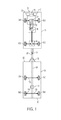
- Fig. 1 illustrates a towing vehicle 15 and a trailer 20.
- the vehicle 15 is coupled to the trailer 20 by a hitch system 25.
- the hitch system 25 includes a hitch ball and a ball receiver.
- other hitching systems are used to couple to the tow vehicle 15 to the trailer 20.
- An operator i.e., a driver
- An operator of the vehicle 15 operates a throttle and brake, and turns a steering wheel to direct the vehicle in a desired direction.
- a system 30 (described in greater detail below) for stabilizing trailer sway determines whether the trailer 20 is swaying and regulates the torque distributed to the wheels of the vehicle 15 in order to control the trailer sway without braking or stopping the vehicle 15 or the trailer 20.
- the process of detecting and determining trailer sway in vehicle towing systems is described in U.S. Patent Application No. 12/512,783, filed on July 30, 2009 (which is incorporated herein by reference).
- the trailer sway stabilizing system 30 includes an Electronic Control Unit (ECU) (or controller) 32, a plurality of sensors 40, and a controllable four-wheel drive coupling device 45 connecting the engine 50 and the transmission 55 of the vehicle with a torque vectoring device 60.
- the vehicle 15 includes four wheels 65, where two of the wheels (65A and 65 B) are located at the front end of the vehicle and the other two wheels (65C and 65D) are at the back end of the vehicle.
- the two back wheels 65C and 65D are mechanically connected to the torque vectoring device 60.
- the torque vectoring device 60 is operable to receive instructions from the controller 32 and to transfer drive torque between the back wheels 65C and 65D while the vehicle is moving in order to mitigate the sway created by the trailer 20.
- the ESP controller of the Electronic Stability Program system (“ESP®) created by Robert Bosch is modified with software in accordance with the teachings herein and used as the controller 32.
- the sensors 40 are used to sense current operating conditions of the vehicle 15 and provide information representative of the same to the controller 32.
- the sensors 40 transmit sensor measurement data in a defined data structure that can include analog data or digital data. These sensors 40 include one or more wheel speed sensors, yaw rate sensors, lateral acceleration sensors, steering angle sensors, and brake pressure sensors. In other embodiments, the vehicle 15 could include more or less sensors. In embodiments utilizing the ESP system, the sensors 40 are the sensors incorporated in that system. If the sensors are equipped with calibration circuitry or a processor, the sensors can internally convert the sensed conditions to a calibrated form. Otherwise, the sensed conditions can be converted into calibrated signals by other external processes, e.g., the ECU 32).
- the sensors 40 can be connected directly to the ECU 32 or connected to a network, such as a controller area network (CAN) bus 70, which is connected to the controller 32.
- the CAN bus 70 is connected to other vehicle systems.
- the trailer 20 includes a frame 75 with a tongue 80, a front cross beam 85, and a rear cross beam 90.
- the tongue 80 includes a hitch ball receiver 87 at a first end and extends to the rear cross beam 90.
- the tongue is located at the approximate midpoint between the left wheels 95A/95B and the right wheels 95C/95D of the trailer 20.
- the left wheels 95A/95B and the right wheels 95C/95D are joined by axles 105.
- the trailer 20 can have different numbers of axles (e.g., two) (and, therefore, a different number of wheels), and can be a semi-trailer, a full-size trailer, a boat trailer, a camper, or the like.
- Attached to each wheels 95A and 95B are trailer brakes 110 used to supply braking force to the associated wheel.
- a hydraulic braking unit 115 is included on the trailer 20.
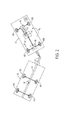
- Fig. 2 and 3 illustrate some of the different sway variations of the trailer 20 that are controlled by the system 30.
- Fig. 2 shows a situation where the vehicle 15 is turning left (i.e., counterclockwise) and, consequently, because the hitching system 25 leads the trailer 20 in the direction of the vehicle, the trailer is also swaying to the left.
- Arrow MT illustrates the torque generated by the trailer 20 based on the trailer sway.
- the torque MT generated by the trailer sway is transferred to the vehicle 15 in the form of resultant vehicle torque MV that has a direction opposite to the direction of the trailer torque MT.
- the system 30 distributes counter torque MTVD to the left back wheel 65C of the vehicle 15.
- the torque MTVD is generated by the engine 50 and is distributed by the torque vectoring device 60 in a process that is be described in more detail below.
- Fig 3 illustrates a situation where the vehicle 15 is turning right (i.e., clockwise) and, consequently, the trailer 20 is also swaying to the right.
- Arrow MT again represents the torque generated by the trailer 20 due to the trailer sway.
- the trailer sway torque MT is transferred to the vehicle 15 in the form of resultant vehicle torque Mv that again has a direction opposite to the direction of the trailer torque MT.
- the system 30 uses the torque vectoring device 60 to distribute counter torque MTVD to the right back wheel 65D of the vehicle 15.
- trailer oscillation can occur not only during turning situations but also when the vehicle 15 is driving in a straight line (forward or backward).
- Some of the reasons for this type of trailer sway include road conditions (e.g. driving over potholes, road bumps, or other objects on the road), traffic (e.g., sudden braking due to traffic congestion or accident), position and quantity of the load of the trailer 20, and the speed of the vehicle 15.
- the system 30 is configured to regulate the trailer sway created while driving in a straight line or cornering without braking or slowing down the vehicle 15.
- the system 30 distributes torque between the back wheels 65C and 65D with the torque vectoring device 60.
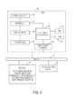
- Fig. 4 schematically illustrates the components of the ECU 32 and the connections between the ECU 32, the sensors 40, the torque vectoring device 60, and the CAN bus 70.
- the controller 32 receives sensor readings (sensor data) from the sensors and processes that data with the controller 32 to stabilize the trailer sway. In some embodiments, the controller 32 obtains sensor readings directly from the sensors 40 rather than over the bus 70.
- the system 30 includes a wheel speed sensor 160, a yaw rate sensor 165, a lateral acceleration sensor 170, a steering angle sensor 175, and a brake pressure sensor 180.
- the controller 32 includes an EPU 120, an input/output interface 125, and one or more memory modules, such as a random access memory (“RAM”) 130 and read-only memory (“ROM”) 135.
- the EPU 120 is implemented as a microprocessor, microcontroller, or other programmable device (e.g., a field programmable gate array (FPGA), an application specific integrated circuit (ASIC), or the like).
- the EPU 120 executes software that can be stored in the RAM 130 (particularly during execution), the ROM 135 (on a generally permanent basis), or another non-transitory computer readable medium such as other memory or disc. If necessary, the microcontroller can be connected to such memory or a disc drive to read such software.
- the RAM 130 and the ROM 135 can be internal to the processor 120, external to the processor 120, or a combination thereof.
- the EPU 120 sends information (e.g., information received from the bus 70 or information generated by the modules executed by the EPU 120) to the RAM 130. Further, the RAM 130 can receive and store data from other components of the system 30. While RAM 130 is used in the embodiment shown in Fig. 5 , other memory devices can be also implemented.
- the controller 32 electronically communicates with the sensors 40 and the torque vectoring device 60 in order to regulate the trailer sway.
- the input/output interface 125 transmits and/or receives information over the bus 70, including sensor readings from the sensors 40.
- the controller 32 also includes a variety of systems (e.g., in the form of hardware) and modules that are stored as instructions in a memory (e.g., RAM 130 or ROM 135) and are executed by the EPU 120.
- the controller 32 comprises an application or software module 140, a band-pass filter 145, a plurality of summing nodes circuits 150, and a proportional integral derivative ("PID") controller 155.
- the software module 140 is the Software module of the ESP controller in Robert Bosch's ESP system.
- the software module 140 is a software program executed by the EPU 120 and is architected to evaluate the sensor data received from the sensors 40 to determine a current vehicle yaw rate, a target vehicle yaw rate, and a yaw rate error of the vehicle 15. Further, the software module 140 is architected to communicate with the other elements of the controller 32 (e.g., the band-pass filter 145 and the PID controller) to determine a trailer yaw rate and a torque distribution signal, and to transmit this torque distribution signal to the torque vectoring device 60.
- the torque vectoring device 60 is operable to distribute a compensatory wheel torque to the wheels 65 based on the torque distribution signal in order to stabilize the sway of the trailer.
- the operation of the system 30 is illustrated in Fig. 5 .
- the system 30 is configured to control and stabilize the sway of the trailer 20 pulled by the vehicle 15 while the vehicle is still moving by using the controller 32 and the torque vectoring device 60.
- the software module 140 of the controller 32 receives sensor readings from the sensors 40.
- the yaw rate sensor 165 measures the yaw rate of the vehicle 15 and the steering angle sensor 175 measures the syteering angle of the steering wheel of the vehicle 15. These readings along with the other measured data is outputed to the software module 140 of the controller 32 as a digital or analog signal.
- more than one yaw rate sensor 165 is used in order to provide redundancy in case of failure or error in one of the yaw rate sensors 165.
- the software module 140 receives the sensor readings from the sensors 40 and is configured to process the received readings. As mentioned above, one of the inputs to the module 140 is the vehicle yaw rate 183 of the vehicle 15. Based on the sensor data, the software module 140 calculates the speed of the vehicle 15. Further, the software module 140 analyzes the information about the steering wheel angle received from the steering angle sensor 175. The module 140 determines whether the driver is actually steering the vehicle intentionally or the oscillation of the vehicle is based on the trailer sway. The module 140 further determines if the vehicle 15 is traveling in a straight line or is cornering. By using the determined vehicle speed, the vehicle yaw rate 183, and by evaluating the data from the sensors 40, the software module determines a target vehicle yaw rate 185. The target yaw rate 185 represents the driver-intended yaw rate of the vehicle 15 based on the analyzed characteristics.
- the controller 32 provides the target vehicle yaw rate 185 determined by the software module 140 to a first summing node circuit 150.
- the other input to the first summing node circuit 150 is the current vehicle yaw rate 183 filtered by the software module 140.
- the output from the first summing node circuit 150 is a yaw rate error signal E1 that shows the difference between the target vehicle yaw rate 185 intended by the driver and the current vehicle yaw rate 183 measured by the system 30.
- the yaw rate error signal E1 represents the level of input of the trailer sway to the vehicle yaw rate.
- the determined yaw rate error signal E1 is inputted into the band-pass filter 145.
- the band-pass filter 145 filters the yaw rate error signal E1 and passes signals of specific frequency that are indicative of the trailer sway. This helps to distinguish between the actual trailer sway and driver assisted sway where the vehicle oscillates due to the fact that the driver intentionally cause the vehicle to turn by moving the steering wheel.
- the band-pass filter 145 can be configured to filter the received signal and to pass signals that have frequencies between 0.5 Hz and 1.5 Hz.
- the yaw rate error signal has very low or very high frequency, the system determines that this is not caused by the trailer sway.
- Such low or high frequencies of the yaw rate error signal can be created by driving fast or steering the vehicle by the driver.
- the band-pass filter 145 outputs a signal 187 that represents the actual yaw rate of the trailer 20. That signal is inputted into a second summing node circuit 150.
- the second input to the second summing mode circuit 150 is a trailer target yaw rate 189.
- the value of the trailer target yaw rate 189 depends on the moving direction of the vehicle and the trailer. For example, when the vehicle and the trailer move in a straight direction, the trailer target yaw rate 189 is always a constant zero because the driver wants to move straight.
- the output of the second summing mode circuit 150 is an asymmetric controller signal E2 that will bring the vehicle and the trailer to a steady state (e.g., driver intended state).
- the outputted asymmetric controller signal E2 can be different depending on the current traveling situation of the vehicle 15 and the trailer 20. For example, during cornering of the vehicle 15 the trailer 20 must sustain a certain yaw rate in order to make the corner along with the vehicle. In that case, the trailer target yaw rate 189 is greater than zero.
- the controller 32 evaluates the speed and the position of the vehicle 15 and the trailer 20, and determines the trailer target yaw rate needed for the trailer to make that corner. Based on that determination, the controller 32 outputs the appropriate asymmetric controller signal E2 (a signal that is greater than zero).
- the controller 32 determines that the trailer must travel with no yaw rate at all (e.g., when the vehicle is driving straight) and it should not be oscillating at all. In that situation, trailer target yaw rate 189 is zero and the outputted asymmetric controller signal E2 would require the system 30 to produce the appropriate amount of torque that would stabilize the trailer 20 completely.
- the asymmetric controller signal E2 output from the second summing node circuit 150 is input into the PID controller 155.
- the role of the PID controller is to amplify the asymmetric controller signal E2 by converting it to a voltage signal.
- the PID controller 155 outputs a continuous asymmetric torque distribution signal 190 that is transmitted to the torque vectoring device 60.
- the continuous asymmetric torque distribution signal 190 includes information about the compensatory wheel torque that the torque vectoring device 60 needs to distribute to the back wheels of the vehicle 15 to stabilize the sway of the trailer. The torque transferred between the wheels of the vehicle 15 counters the trailer sway and stabilizes the trailer 20 without braking or slowing down the vehicle.
- the torque vectoring device 60 includes a controller that executes software stored on a memory (elements not shown).
- the torque vectoring device 60 receives the continuous asymmetric torque distribution signal 190 and distributes compensatory wheel torque either to the left back wheel, the right back wheel, or both back wheels as directed by the signal 190 in order to stabilize the trailer sway.
- the torque vectoring device 60 transfers torque from the right back wheel to the left back wheel (e.g., when the trailer sways to the left, Fig. 2 ).
- the torque vectoring device 60 transfers torque from the left back wheel to the right back wheel (e.g., when the trailer sways to the right, Fig. 3 ).
- the torque vectoring device 60 transfers torque to both, the right and the left back when necessary (e.g., when the trailer sways to the left and the to the right but the vehicle is traveling straight, Fig. 1 ).
- the torque vectoring device 60 needs additional compensatory wheel torque in order to control the trailer sway.
- the torque vectoring device 60 does not produce any torque on its own but only distributes torque based on the asymmetric torque distribution signal 190.
- the additional torque is generally produced or generated by the engine 50.
- the torque vectoring device 60 sends a compensatory wheel torque request to the four-wheel drive coupling device 45 based on the torque distribution signal 190.
- the four-wheel drive coupling device 45 includes a controller that executes software stored on a memory and determines how much torque is currently transferred from the engine 50 to the torque vectoring device 60. Based on that determination and the request from the torque vectoring device 60, the four-wheel drive coupling device 45 transfers the necessary torque from the engine 50 to the torque vectoring device 60.
- the transfer and control of torque from the torque vectoring device 60 to the back wheels 65B is completed, in one configuration, by using a clutch plate (not shown).
- the amount of torque transmitted to the clutch plate from the engine 50 is regulated by the torque vectoring device 60 and the clutch plate distributes the torque to an input shaft that drives an output shaft, which distributes the torque to the wheels 65B.
- the transfer and control of torque is completed by using a motor (not shown) that connects the torque vectoring device 60 and the back wheels 65B.
- Fig. 6 illustrates a method 200 of stabilizing the trailer sway of a trailer 20 during the movement of the vehicle 15 by using the system 30.
- the method 200 is carried out by the ECU 32 shown in Fig. 2 .
- the controller 32 of the system 30 receives sensor data from the sensors 40 (step 205) and the controller 32 processes the sensor data using the software module 140 (step 210).
- the software module 140 determines if the vehicle 15 is traveling in a straight line or is cornering, the target vehicle yaw rate 185, and the current vehicle yaw rate 183 based on the sensor data (step 215).
- the system 30 uses the first summing node circuit 150 to determine a yaw rate error E1 that indicates the difference between the driver intended target vehicle yaw rate 185 and the current vehicle yaw rate 183 (step 220).
- the system 30 determines the actual trailer yaw rate 187 of the trailer 20 by passing the yaw rate error signal E1 through the band-pass filter 145 (step 225). Then, the system 30 determines the asymmetric controller signal E2 by using the second summing node circuit 150 that inputs the actual trailer yaw rate 187 and the trailer target yaw rate 189 that is equal to zero (when driving straight) or is greater than zero (when cornering) (step 230). Using the PID controller 155, the system transforms the asymmetric controller signal E2 and produces the continuous asymmetric torque distribution signal 190 that is provided to the torque vectoring device 60 in order to stabilize the oscillation of the trailer without braking the vehicle (step 235).
- the torque vectoring device 60 analyzes the torque distribution signal 190 and determines the amount of torque that needs to be transferred to the back wheels (step 240). If the torque vectoring device 60 determines that the amount of torque that is currently available in the back wheels is sufficient to stabilize the trailer sway (step 245), the torque vectoring device 60 transfers the torque between the wheels as directed by the torque distribution signal 190 (step 250). The transferred torque counters the trailer sway and stabilizes the trailer 20. If the torque vectoring device 60 determines that the amount of torque that is currently available in the back wheels is insufficient to stabilize the trailer sway (step 245), the torque vectoring device 60 requests additional torque from the controllable four-wheel drive coupling device 45 (step 255). When torque vectoring device 60 receives the neccesery torque from the engine 50 via the four-wheel drive coupling device 45, the torque vectoring device 60 transfers the torque to the wheels and stabilizes the sway of the trailer (step 250).
Landscapes
- Engineering & Computer Science (AREA)
- Transportation (AREA)
- Mechanical Engineering (AREA)
- Automation & Control Theory (AREA)
- Regulating Braking Force (AREA)
- Control Of Driving Devices And Active Controlling Of Vehicle (AREA)
- Arrangement And Driving Of Transmission Devices (AREA)
Claims (19)
- System (30) zum Stabilisieren des Pendelns eines Anhängers (20), der an einem Fahrzeug (15) befestigt ist, wobei das Fahrzeug ein linkes Hinterrad (65C) und ein rechtes Hinterrad (65D) aufweist,
wobei das System (30) Folgendes umfasst:eine Steuereinheit (32);mehrere Sensoren (40) in elektronischer Kommunikation mit der Steuereinheit (32), wobei jeder der Sensoren (40) Sensordaten an die Steuereinheit (32) überträgt;eine Drehmomentvektorisierungsvorrichtung (60) in elektronischer Kommunikation mit der Steuereinheit (32); undeinen computerlesbaren Speicher (130, 135), der Befehle speichert, die dann, wenn sie von der Steuereinheit (32) ausgeführt werden, die Steuereinheit (32) dazu veranlassen:dadurch gekennzeichnet, dass das Drehmomentverteilungssignal an die Drehmomentvektorisierungsvorrichtung (60) übertragen wird, um das Pendeln des Anhängers (20) ohne Bremsen des Fahrzeugs (15) zu stabilisieren, wobei die Drehmomentvektorisierungsvorrichtung (60) Drehmoment von dem rechten Hinterrad (65D) an das linke Hinterrad (65C) überträgt, wenn der Anhänger (20) nach links pendelt, Drehmoment von dem linken Hinterrad (65C) an das rechte Hinterrad (65D) überträgt, wenn der Anhänger (20) nach rechts pendelt, und Drehmoment sowohl an das rechte als auch an das linke Hinterrad (65C, 65D) überträgt, wenn der Anhänger (20) nach links oder nach rechts pendelt, das Fahrzeug (15) jedoch geradeaus fährt.die von den Sensoren (40) empfangenen Sensordaten zu bewerten, um eine Ist-Fahrzeuggierrate, eine Soll-Fahrzeuggierrate und einen Gierratenfehler des Fahrzeugs (15) zu bestimmen,zu bestimmen, ob das Fahrzeug (15) auf einer geraden Linie fährt,ein Drehmomentverteilungssignal zu bestimmen, - System (30) nach Anspruch 1, wobei der computerlesbare Speicher (130, 135) ferner Befehle von einem Software-Modul (140) speichert, die dann, wenn sie von der Steuereinheit (32) ausgeführt werden, die Ist-Fahrzeuggierrate und die Soll-Fahrzeuggierrate bestimmen.
- System (30) nach Anspruch 1, das ferner eine erste Summationsknotenschaltung (150) umfasst, die eine Differenz zwischen der Soll-Fahrzeuggierrate und der Ist-Fahrzeuggierrate berechnet und den Gierratenfehler bestimmt.
- System (30) nach Anspruch 1, das ferner ein Bandpassfilter (145) umfasst, das den Gierratenfehler filtert, um eine aktuelle Anhänger-Gierrate zu bestimmen.
- System (30) nach Anspruch 4, das ferner eine zweite Summationsknotenschaltung (150) umfasst, die ein asymmetrisches Steuereinheitssignal unter Verwendung der aktuellen Anhänger-Gierrate und einer Anhänger-Sollgierrate bestimmt.
- System (30) nach Anspruch 5, das ferner eine Proportional-Integral-Differential-Steuereinheit (155) umfasst, die das asymmetrische Steuereinheitssignal empfängt und das Drehmomentverteilungssignal an die Drehmomentvektorisierungsvorrichtung (60) ausgibt.
- System (30) nach Anspruch 1, wobei das Drehmomentverteilungssignal Informationen über ein ausgleichendes Raddrehmoment enthält, das die Drehmomentvektorisierungsvorrichtung (60) auf ein oder mehrere Fahrzeugräder (65) verteilt, um das Pendeln des Anhängers zu stabilisieren.
- System (30) nach Anspruch 1, wobei die Drehmomentvektorisierungsvorrichtung (60) eine Anforderung für ein ausgleichendes Raddrehmoment an eine steuerbare Vierradantrieb-Kopplungsvorrichtung (45) anhand des Drehmomentverteilungssignals sendet.
- System (30) nach Anspruch 8, wobei ein ausgleichendes Raddrehmoment durch eine Kraftmaschine (50) erzeugt wird und durch die steuerbare Vierradantrieb-Kopplungsvorrichtung (45) an die Drehmomentvektorisierungsvorrichtung (60) übertragen wird.
- Verfahren zum Stabilisieren des Pendels eines Anhängers (20), der an einem Fahrzeug (15) befestigt ist, wobei das Fahrzeug ein linkes Hinterrad (65C) und ein rechtes Hinterrad (65D) aufweist,
wobei das Verfahren Folgendes umfasst:Empfangen von Sensordaten von mehreren Sensoren (40) bei einer Steuereinheit (32);Bewerten der Sensordaten, die von den Sensoren (40) empfangen werden;Bestimmen einer Ist-Fahrzeuggierrate, einer Soll-Fahrzeuggierrate und eines Gierratenfehlers des Fahrzeugs;Bestimmen, ob das Fahrzeug (15) auf einer geraden Linie fährt;Bestimmen eines Drehmomentverteilungssignals; undÜbertragen des Drehmomentverteilungssignals an eine Drehmomentvektorisierungsvorrichtung (60);dadurch gekennzeichnet, dass das Verfahren ferner umfasst:Stabilisieren des Pendelns des Anhängers (20) ohne Bremsen des Fahrzeugs (15) anhand des Drehmomentverteilungssignals, das von der Drehmomentvektorisierungsvorrichtung (60) empfangen wird, wobei die Drehmomentvektorisierungsvorrichtung (60) Drehmoment von dem rechten Hinterrad (65D) an das linke Hinterrad (65C) überträgt, wenn der Anhänger (20) nach links pendelt, Drehmoment von dem linken Hinterrad (65C) an das rechte Hinterrad (65D) überträgt, wenn der Anhänger (20) nach rechts pendelt, und Drehmoment sowohl an das rechte als auch an das linke Hinterrad (65C, 65D) überträgt, wenn der Anhänger (20) nach links oder nach rechts pendelt, das Fahrzeug (15) jedoch geradeaus fährt. - Verfahren nach Anspruch 10, wobei das Bestimmen der Ist-Fahrzeuggierrate und der Soll-Fahrzeuggierrate ferner das Ausführen eines Software-Moduls umfasst und das Bestimmen des Gierratenfehlers ferner das Ausführen einer ersten Summationsknotenschaltung (150) umfasst.
- Verfahren nach Anspruch 10, das ferner das Bestimmen einer aktuellen Gierrate des Anhängers (20) unter Verwendung eines Bandpassfilters (145), um den Gierratenfehler zu filtern, umfasst.
- Verfahren nach Anspruch 10, das ferner das Bestimmen eines asymmetrischen Steuereinheitssignals unter Verwendung einer zweiten Summationsknotenschaltung (150), die die aktuelle Anhänger-Gierrate und eine Anhänger-Sollgierrate eingibt, umfasst.
- Verfahren nach Anspruch 10, das ferner das Bereitstellen von Informationen über ein ausgleichendes Raddrehmoment, das die Drehmomentvektorisierungsvorrichtung (40) an ein oder mehrere Fahrzeugräder (65) verteilt, um das Pendeln des Anhängers (20) zu stabilisieren, umfasst, wobei diese Informationen in dem Drehmomentverteilungssignal enthalten sind.
- Verfahren nach Anspruch 14, das ferner Folgendes umfasst:Verteilen des ausgleichenden Raddrehmoments an ein linkes Hinterrad (65C) und/oder an ein rechtes Hinterrad (65D).
- Verfahren nach Anspruch 14, das ferner das Übertragen des ausgleichenden Raddrehmoments von dem rechten Hinterrad (65D) an das linke Hinterrad (65C) umfasst.
- Verfahren nach Anspruch 14, das ferner das Übertragen des ausgleichenden Raddrehmoments von dem linken Hinterrad (65C) an das rechte Hinterrad (65D) umfasst.
- Verfahren nach Anspruch 10, das ferner das Senden einer Anforderung für ein ausgleichendes Raddrehmoment an eine steuerbare Vierradantrieb-Kopplungsvorrichtung (45) anhand des Drehmomentverteilungssignals umfasst.
- Verfahren nach Anspruch 18, das ferner das Erzeugen eines ausgleichenden Raddrehmoments durch eine Kraftmaschine (50) und das Übertragen des ausgleichenden Raddrehmoments an die Drehmomentvektorisierungsvorrichtung (60) durch die steuerbare Vierradantrieb-Kopplungsvorrichtung (45) umfasst.
Applications Claiming Priority (2)
| Application Number | Priority Date | Filing Date | Title |
|---|---|---|---|
| US12/913,204 US9061663B2 (en) | 2010-10-27 | 2010-10-27 | Trailer sway mitigation using torque vectoring |
| PCT/US2011/057799 WO2012058259A2 (en) | 2010-10-27 | 2011-10-26 | Trailer sway mitigation using torque vectoring |
Publications (2)
| Publication Number | Publication Date |
|---|---|
| EP2633452A2 EP2633452A2 (de) | 2013-09-04 |
| EP2633452B1 true EP2633452B1 (de) | 2015-12-30 |
Family
ID=44910309
Family Applications (1)
| Application Number | Title | Priority Date | Filing Date |
|---|---|---|---|
| EP11779527.8A Active EP2633452B1 (de) | 2010-10-27 | 2011-10-26 | Anhängerschwingungsdämpfung anhand von drehmomentvektorierung |
Country Status (4)
| Country | Link |
|---|---|
| US (1) | US9061663B2 (de) |
| EP (1) | EP2633452B1 (de) |
| JP (1) | JP5923101B2 (de) |
| WO (1) | WO2012058259A2 (de) |
Cited By (1)
| Publication number | Priority date | Publication date | Assignee | Title |
|---|---|---|---|---|
| CN110466523A (zh) * | 2019-09-02 | 2019-11-19 | 湖南行必达网联科技有限公司 | 牵引车制动一致性判断方法、装置及牵引车 |
Families Citing this family (56)
| Publication number | Priority date | Publication date | Assignee | Title |
|---|---|---|---|---|
| GB2447672B (en) | 2007-03-21 | 2011-12-14 | Ford Global Tech Llc | Vehicle manoeuvring aids |
| US9061663B2 (en) * | 2010-10-27 | 2015-06-23 | Robert Bosch Gmbh | Trailer sway mitigation using torque vectoring |
| US9290203B2 (en) | 2011-04-19 | 2016-03-22 | Ford Global Technologies, Llc | Trailer length estimation in hitch angle applications |
| US10196088B2 (en) | 2011-04-19 | 2019-02-05 | Ford Global Technologies, Llc | Target monitoring system and method |
| US8755984B2 (en) | 2011-04-19 | 2014-06-17 | Ford Global Technologies | Managing jackknife enabling conditions during backing of a trailer by reducing speed of a vehicle backing the trailer |
| US9513103B2 (en) | 2011-04-19 | 2016-12-06 | Ford Global Technologies, Llc | Hitch angle sensor assembly |
| US9290202B2 (en) * | 2011-04-19 | 2016-03-22 | Ford Global Technologies, Llc | System and method of calibrating a trailer backup assist system |
| US8825328B2 (en) | 2011-04-19 | 2014-09-02 | Ford Global Technologies | Detection of and counter-measures for jackknife enabling conditions during trailer backup assist |
| US9434414B2 (en) | 2011-04-19 | 2016-09-06 | Ford Global Technologies, Llc | System and method for determining a hitch angle offset |
| US9937953B2 (en) | 2011-04-19 | 2018-04-10 | Ford Global Technologies, Llc | Trailer backup offset determination |
| US9248858B2 (en) | 2011-04-19 | 2016-02-02 | Ford Global Technologies | Trailer backup assist system |
| US9335163B2 (en) | 2011-04-19 | 2016-05-10 | Ford Global Technologies, Llc | Trailer length estimation in hitch angle applications |
| WO2013066216A1 (en) * | 2011-10-31 | 2013-05-10 | Volvo Lastvagnar Ab | Method and arrangement for vehicle stabilization |
| AU2011380326A1 (en) * | 2011-10-31 | 2014-04-24 | Volvo Lastvagnar Ab | Method and arrangement for vehichle stabilization |
| JP6036198B2 (ja) * | 2012-11-13 | 2016-11-30 | 株式会社デンソー | 運転支援装置及び運転支援システム |
| US9026311B1 (en) * | 2013-03-13 | 2015-05-05 | Tuson Rv Brakes, Llc | Trailer sway detection and method for reducing trailer sway utilizing trailer brakes |
| JP6176966B2 (ja) * | 2013-03-28 | 2017-08-09 | 株式会社ビデオリサーチ | 情報提供装置及びシステム及び方法及びプログラム |
| US9517668B2 (en) | 2014-07-28 | 2016-12-13 | Ford Global Technologies, Llc | Hitch angle warning system and method |
| US9963004B2 (en) | 2014-07-28 | 2018-05-08 | Ford Global Technologies, Llc | Trailer sway warning system and method |
| US9340228B2 (en) | 2014-10-13 | 2016-05-17 | Ford Global Technologies, Llc | Trailer motion and parameter estimation system |
| US9315212B1 (en) | 2014-10-13 | 2016-04-19 | Ford Global Technologies, Llc | Trailer sensor module and associated method of wireless trailer identification and motion estimation |
| US9533683B2 (en) | 2014-12-05 | 2017-01-03 | Ford Global Technologies, Llc | Sensor failure mitigation system and mode management |
| US9607242B2 (en) | 2015-01-16 | 2017-03-28 | Ford Global Technologies, Llc | Target monitoring system with lens cleaning device |
| US9522699B2 (en) | 2015-02-05 | 2016-12-20 | Ford Global Technologies, Llc | Trailer backup assist system with adaptive steering angle limits |
| US9616923B2 (en) | 2015-03-03 | 2017-04-11 | Ford Global Technologies, Llc | Topographical integration for trailer backup assist system |
| US9804022B2 (en) | 2015-03-24 | 2017-10-31 | Ford Global Technologies, Llc | System and method for hitch angle detection |
| US10384607B2 (en) | 2015-10-19 | 2019-08-20 | Ford Global Technologies, Llc | Trailer backup assist system with hitch angle offset estimation |
| US10611407B2 (en) | 2015-10-19 | 2020-04-07 | Ford Global Technologies, Llc | Speed control for motor vehicles |
| US9836060B2 (en) | 2015-10-28 | 2017-12-05 | Ford Global Technologies, Llc | Trailer backup assist system with target management |
| US10017115B2 (en) | 2015-11-11 | 2018-07-10 | Ford Global Technologies, Llc | Trailer monitoring system and method |
| US9798953B2 (en) | 2015-12-17 | 2017-10-24 | Ford Global Technologies, Llc | Template matching solution for locating trailer hitch point |
| US9934572B2 (en) | 2015-12-17 | 2018-04-03 | Ford Global Technologies, Llc | Drawbar scan solution for locating trailer hitch point |
| US9796228B2 (en) | 2015-12-17 | 2017-10-24 | Ford Global Technologies, Llc | Hitch angle detection for trailer backup assist system |
| US10011228B2 (en) | 2015-12-17 | 2018-07-03 | Ford Global Technologies, Llc | Hitch angle detection for trailer backup assist system using multiple imaging devices |
| US10155478B2 (en) | 2015-12-17 | 2018-12-18 | Ford Global Technologies, Llc | Centerline method for trailer hitch angle detection |
| US9827818B2 (en) | 2015-12-17 | 2017-11-28 | Ford Global Technologies, Llc | Multi-stage solution for trailer hitch angle initialization |
| US9610975B1 (en) | 2015-12-17 | 2017-04-04 | Ford Global Technologies, Llc | Hitch angle detection for trailer backup assist system |
| DE102016200926A1 (de) | 2016-01-22 | 2017-07-27 | Ford Global Technologies, Llc | Anpassungsverfahren und Kraftfahrzeug |
| US10005492B2 (en) | 2016-02-18 | 2018-06-26 | Ford Global Technologies, Llc | Trailer length and hitch angle bias estimation |
| US10071729B2 (en) | 2016-05-16 | 2018-09-11 | Ford Global Technologies, Llc | Tow damping system |
| US10106193B2 (en) | 2016-07-01 | 2018-10-23 | Ford Global Technologies, Llc | Enhanced yaw rate trailer angle detection initialization |
| US10919520B1 (en) * | 2016-08-03 | 2021-02-16 | Apple Inc. | Integrated chassis control |
| US10046800B2 (en) | 2016-08-10 | 2018-08-14 | Ford Global Technologies, Llc | Trailer wheel targetless trailer angle detection |
| US10222804B2 (en) | 2016-10-21 | 2019-03-05 | Ford Global Technologies, Llc | Inertial reference for TBA speed limiting |
| US10202106B1 (en) * | 2017-08-08 | 2019-02-12 | Ford Global Technologies, Llc | Vehicle trailer detection |
| US10710585B2 (en) | 2017-09-01 | 2020-07-14 | Ford Global Technologies, Llc | Trailer backup assist system with predictive hitch angle functionality |
| RU2668141C1 (ru) * | 2017-11-07 | 2018-09-26 | федеральное государственное бюджетное образовательное учреждение высшего образования "Волгоградский государственный аграрный университет" (ФГБОУ ВО Волгоградский ГАУ) | Способ и устройство для стабилизации крутящего момента на ведущих колесах |
| JP2019127095A (ja) * | 2018-01-23 | 2019-08-01 | マツダ株式会社 | 車両の制御装置 |
| US11077795B2 (en) | 2018-11-26 | 2021-08-03 | Ford Global Technologies, Llc | Trailer angle detection using end-to-end learning |
| US11220255B2 (en) * | 2019-01-30 | 2022-01-11 | Toyota Motor Engineering & Manufacturing North America, Inc. | Systems and methods for mitigating trailer instability due to pressure differentials |
| US10829046B2 (en) | 2019-03-06 | 2020-11-10 | Ford Global Technologies, Llc | Trailer angle detection using end-to-end learning |
| WO2021127693A1 (en) * | 2019-12-16 | 2021-06-24 | Magna Electronics Inc. | Vehicular trailering guidance system |
| US11827231B2 (en) * | 2020-12-28 | 2023-11-28 | GM Global Technology Operations LLC | System and method for evaluating vehicle-trailer combination for trailer sway potential using active yaw maneuver |
| EP4234367B1 (de) | 2022-02-24 | 2024-11-20 | Volvo Truck Corporation | Verfahren zur steuerung der drehmomentvektorisierung für fahrzeuge |
| US12194985B2 (en) | 2022-03-09 | 2025-01-14 | Robert Bosch Gmbh | Trailer sway mitigation with steering systems |
| EP4494911B1 (de) * | 2023-07-21 | 2026-04-01 | AUMOVIO Germany GmbH | Verfahren zur erhöhung der kurvenstabilität eines fahrzeugs und elektronisches steuergerät |
Family Cites Families (62)
| Publication number | Priority date | Publication date | Assignee | Title |
|---|---|---|---|---|
| USRE30550E (en) | 1975-11-06 | 1981-03-24 | Durrell U. Howard | Automatic trailer sway sensing and brake applying system |
| US4023863A (en) | 1975-11-24 | 1977-05-17 | The Bendix Corporation | Sway control system for a tow vehicle-trailer combination |
| US4034822A (en) | 1976-04-05 | 1977-07-12 | Caterpillar Tractor Co. | Hitch-steering, oscillation and differential support for a mining machine or the like |
| ES232357Y (es) | 1977-11-22 | 1978-06-16 | Amortiguador de oscilaciones para enganches de remolques. | |
| US4254998A (en) | 1978-10-30 | 1981-03-10 | Epco Mobilehome Products, Inc. | Trailer sway-control and braking system |
| US5011170A (en) | 1990-03-26 | 1991-04-30 | Forbes Alexander D | Pedal cycle and motorcycle trailer |
| EP0663872A4 (de) | 1992-10-13 | 1995-11-15 | Presbat Products Pty Ltd | Anti-schlinger system. |
| JP3318420B2 (ja) * | 1993-12-17 | 2002-08-26 | マツダ株式会社 | 自動車の駆動力配分制御装置 |
| DE19515050A1 (de) | 1994-11-25 | 1996-05-30 | Teves Gmbh Alfred | Verfahren zur Fahrstabilitätsregelschaltung mit Steuerung über Druckgradienten |
| JP3225790B2 (ja) | 1995-06-09 | 2001-11-05 | トヨタ自動車株式会社 | 車両挙動制御装置 |
| JPH09156487A (ja) | 1995-12-13 | 1997-06-17 | Fuji Heavy Ind Ltd | 制動力制御装置 |
| EP0798615B1 (de) | 1996-02-27 | 2002-01-02 | KNORR-BREMSE SYSTEME FÜR NUTZFAHRZEUGE GmbH | Verfahren zur Fahrstabilitätserhöhung |
| US6012780A (en) | 1996-04-05 | 2000-01-11 | Reese Products, Inc. | Brake controller for trailer brakes |
| JP3570145B2 (ja) | 1997-02-25 | 2004-09-29 | トヨタ自動車株式会社 | 連結車のトレーラブレーキ制御装置 |
| DE19744066B4 (de) | 1997-10-06 | 2008-06-26 | Knorr-Bremse Systeme für Nutzfahrzeuge GmbH | Verfahren und Vorrichtung zum Erkennen eines Anhängerbetriebs bei einem Kraftfahrzeug |
| US6550810B1 (en) | 1998-03-19 | 2003-04-22 | Trw Vehicle Safety Systems Inc. | Seat belt retractor |
| DE19859953A1 (de) | 1998-12-28 | 2000-06-29 | Bosch Gmbh Robert | Vorrichtung und Verfahren zur Stabilisierung eines aus einem Zugfahrzeug und einem Anhänger bzw. Auflieger bestehenden Fahrzeuggespannes |
| DE19901953B4 (de) | 1999-01-20 | 2014-02-06 | Robert Bosch Gmbh | Vorrichtung und Verfahren zur Stabilisierung eines Fahrzeuggespannes |
| DE19964048A1 (de) | 1999-06-30 | 2001-01-04 | Bosch Gmbh Robert | Verfahren und Einrichtung zum Stabilisieren eines Straßenfahrzeugs |
| JP3997086B2 (ja) | 1999-06-30 | 2007-10-24 | ロベルト・ボッシュ・ゲゼルシャフト・ミト・ベシュレンクテル・ハフツング | 自動車の安定化方法および装置 |
| DE19964058B4 (de) | 1999-12-30 | 2015-11-12 | Knorr-Bremse Systeme für Nutzfahrzeuge GmbH | Einrichtung und Verfahren zum Stabilisieren eines Gespanns aus einer Zugmaschine und zumindest einem Auflieger oder Anhänger |
| DE19964164B4 (de) | 1999-12-30 | 2009-03-26 | Knorr-Bremse Systeme für Nutzfahrzeuge GmbH | Einrichtung und Verfahren zum Stabilisieren eines Gespanns aus einer Zugmaschine und zumindest einem Auflieger oder Anhänger |
| DE10019150A1 (de) | 2000-04-18 | 2001-10-25 | Bosch Gmbh Robert | Verfahren und Vorrichtung zum Schätzen einer Querbeschleunigung an einer Achse eines Aufliegers oder Anhängers einer Fahrzeugkombination |
| US6668225B2 (en) | 2000-11-29 | 2003-12-23 | Visteon Global Technologies, Inc. | Trailer control system |
| JP2002219958A (ja) * | 2001-01-29 | 2002-08-06 | Toyota Motor Corp | 車両用ヨーレイト制御装置 |
| DE10144299B4 (de) | 2001-09-10 | 2005-07-14 | Knorr-Bremse Systeme für Nutzfahrzeuge GmbH | Verfahren zur Fahrzustandsstabilisierung eines Nutzfahrzeugverbandes |
| US6655710B2 (en) | 2002-02-27 | 2003-12-02 | General Motors Corporation | System for detecting trailer instability |
| EP1554162B2 (de) | 2002-10-21 | 2014-03-26 | Autoliv Development Ab | Verbesserungen für eine sicherheitsanordnung für ein fahrzeug oder diese betreffend |
| WO2004041613A1 (de) | 2002-11-08 | 2004-05-21 | Continental Teves Ag & Co.Ohg | Verfahren und einrichtung zum stabilisieren eines gespanns |
| WO2004041614A1 (de) | 2002-11-08 | 2004-05-21 | Continental Teves Ag & Co. Ohg | Verfahren und einrichtung zum stabilisieren eines gespanns |
| DE10393558D2 (de) | 2002-11-08 | 2005-10-20 | Continental Teves Ag & Co Ohg | Verfahren und Einrichtung zum Stabilisieren eines Gespanns |
| US20060125313A1 (en) | 2002-11-22 | 2006-06-15 | Daimlerchrysler Ag | Method and device for stabilizing a semi-trailer |
| US6748307B1 (en) | 2002-11-25 | 2004-06-08 | General Motors Corporation | Collision sensing system |
| US6940026B2 (en) | 2002-12-09 | 2005-09-06 | Robert Bosch Corporation | Method and system for vehicle occupant weight sensing |
| GB2402453B (en) | 2003-06-03 | 2005-04-27 | Bosch Gmbh Robert | Method and device for damping trailer pendulum oscillation |
| JP2004359216A (ja) | 2003-06-03 | 2004-12-24 | Robert Bosch Gmbh | 連結車両の安定化方法および装置 |
| DE10327564A1 (de) | 2003-06-18 | 2005-01-05 | Robert Bosch Gmbh | Verfahren zur Bremsregelung eines Kraftfahrzeug-Anhängers |
| WO2005005200A2 (en) | 2003-06-30 | 2005-01-20 | Kelsey-Hayes Company | Method and apparatus for detecting and correcting trailer induced yaw movements in a towing vehicle |
| US20050065694A1 (en) | 2003-09-18 | 2005-03-24 | Gero Nenninger | Method and device for considering the driver's steering response in stabilizing a vehicle-trailer combination |
| DE10350552A1 (de) | 2003-10-29 | 2005-06-02 | Robert Bosch Gmbh | Fahrwerkunterstütztes Hilfs- bzw. Notbremssystem |
| US6959970B2 (en) | 2004-03-18 | 2005-11-01 | Ford Global Technologies, Llc | Method and apparatus for controlling a trailer and an automotive vehicle with a yaw stability control system |
| EP1758774B1 (de) | 2004-06-25 | 2013-01-16 | Continental Teves AG & Co. oHG | Verfahren und einrichtung zum stabilisieren eines fahrzeugs |
| DE102005028787B4 (de) | 2004-10-22 | 2018-02-22 | Volkswagen Ag | System zur Gespannstabilisierung |
| US7561953B2 (en) | 2005-03-14 | 2009-07-14 | Robert Bosch Gmbh | Method and system of controlling a vehicle in the presence of a disturbance |
| US7640089B2 (en) | 2005-04-06 | 2009-12-29 | Gm Global Technology Operations, Inc. | Vehicle-trailer stability and handling performance improvement using rear-wheel steering control |
| WO2007060135A1 (de) | 2005-11-22 | 2007-05-31 | Continental Teves Ag & Co. Ohg | Verfahren und fahrdynamikregelsystem zum stabilisieren eines fahrzeuggespanns |
| US7798263B2 (en) | 2006-05-03 | 2010-09-21 | Tandy Engineering & Associates, Inc. | Stability enhancing system for tow-vehicle and trailer assembly combination with two processors |
| DE102006029367A1 (de) | 2006-06-27 | 2008-01-03 | Robert Bosch Gmbh | Verfahren und Steuergerät zur Erkennung eines Anhängerbetriebs bei einem Zugfahrzeug |
| DE102006031511A1 (de) * | 2006-07-07 | 2008-01-17 | Robert Bosch Gmbh | Verfahren zum Kompensieren der Bremsverzögerung bei einer Fahrzeugregelung |
| US8740317B2 (en) * | 2006-08-11 | 2014-06-03 | Robert Bosch Gmbh | Closed-loop control for trailer sway mitigation |
| US9834187B2 (en) | 2007-01-11 | 2017-12-05 | Ford Global Technologies, Llc | Trailer sway control with trailer brake intervention |
| JP2009006873A (ja) * | 2007-06-28 | 2009-01-15 | Honda Motor Co Ltd | 車両用駆動制御装置 |
| JP5123584B2 (ja) | 2007-06-29 | 2013-01-23 | 本田技研工業株式会社 | 連結車両の運動安定化装置 |
| JP4636073B2 (ja) * | 2007-09-10 | 2011-02-23 | トヨタ自動車株式会社 | 駆動力配分機構 |
| US8010252B2 (en) | 2007-10-05 | 2011-08-30 | Ford Global Technologies | Trailer oscillation detection and compensation method for a vehicle and trailer combination |
| US7917274B2 (en) * | 2007-10-19 | 2011-03-29 | Advics Co., Ltd. | Method and apparatus for vehicle sway detection and reduction |
| US8260518B2 (en) | 2008-02-06 | 2012-09-04 | Ford Global Technologies, Llc | Trailer sway control with reverse sensors |
| US8091677B2 (en) * | 2008-03-27 | 2012-01-10 | GM Global Technology Operations LLC | System and method of differentiating rotational speed and torque between wheels of a hybrid vehicle |
| US8244442B2 (en) * | 2009-02-17 | 2012-08-14 | Lockheed Martin Corporation | System and method for stability control of vehicle and trailer |
| US8060288B2 (en) | 2009-03-20 | 2011-11-15 | Toyota Motor Engineering & Manufacturing North America, Inc. | Control system and method to inhibit automatic transmission downshifting during trailer sway |
| CN103097222B (zh) * | 2010-08-30 | 2015-10-21 | E-Aam传动系统公司 | 控制扭矩引导机构的方法和扭矩引导系统 |
| US9061663B2 (en) * | 2010-10-27 | 2015-06-23 | Robert Bosch Gmbh | Trailer sway mitigation using torque vectoring |
-
2010
- 2010-10-27 US US12/913,204 patent/US9061663B2/en not_active Expired - Fee Related
-
2011
- 2011-10-26 JP JP2013536767A patent/JP5923101B2/ja not_active Expired - Fee Related
- 2011-10-26 EP EP11779527.8A patent/EP2633452B1/de active Active
- 2011-10-26 WO PCT/US2011/057799 patent/WO2012058259A2/en not_active Ceased
Cited By (2)
| Publication number | Priority date | Publication date | Assignee | Title |
|---|---|---|---|---|
| CN110466523A (zh) * | 2019-09-02 | 2019-11-19 | 湖南行必达网联科技有限公司 | 牵引车制动一致性判断方法、装置及牵引车 |
| CN110466523B (zh) * | 2019-09-02 | 2020-10-13 | 湖南行必达网联科技有限公司 | 牵引车制动一致性判断方法、装置及牵引车 |
Also Published As
| Publication number | Publication date |
|---|---|
| WO2012058259A2 (en) | 2012-05-03 |
| US9061663B2 (en) | 2015-06-23 |
| JP2014501653A (ja) | 2014-01-23 |
| US20120109471A1 (en) | 2012-05-03 |
| JP5923101B2 (ja) | 2016-05-24 |
| WO2012058259A3 (en) | 2012-06-21 |
| EP2633452A2 (de) | 2013-09-04 |
Similar Documents
| Publication | Publication Date | Title |
|---|---|---|
| EP2633452B1 (de) | Anhängerschwingungsdämpfung anhand von drehmomentvektorierung | |
| US8326504B2 (en) | Holistic control for stabilizing vehicle-trailer swaying | |
| US8180543B2 (en) | Movement stabilizing apparatus for combination vehicle | |
| US9834187B2 (en) | Trailer sway control with trailer brake intervention | |
| CN103987603B (zh) | 用于车辆稳定的方法和设备 | |
| EP2051893B1 (de) | Geschlossener regelkreis für anhängerschwingungsdämpfung | |
| US9031754B2 (en) | Towing vehicle controller providing brake control to a towed vehicle and method | |
| US9073524B2 (en) | Braking system and method for a towed vehicle | |
| US7562946B2 (en) | Brake regulating system for stabilizing the motion of a commercial vehicle | |
| US20040021291A1 (en) | Movable trailer hitch for avoiding pendulous movements in vehicle-trailer arrangements | |
| US20150367844A1 (en) | Method and arrangement for vehicle stabilization | |
| CN108473117A (zh) | 用于预测地防止车辆倾翻的方法 | |
| JP2011025921A (ja) | トレーラと牽引車両との間の測定距離を用いたトレーラの揺れ軽減方法及びシステム | |
| US11370400B2 (en) | Braking system | |
| US6289273B1 (en) | Measuring and control system for the tranverse regulation of successive vehicles and method for this purpose | |
| AU2019201871B2 (en) | Brake controller system comprising a trailer mounted brake controller and a towing vehicle mounted brake controller | |
| SE542330C2 (en) | A method and a system for controlling an articulated vehicle | |
| JP7754035B2 (ja) | 衝突回避支援装置及び衝突回避支援プログラム | |
| JP4012353B2 (ja) | 車両挙動安定化装置 | |
| SE541685C2 (en) | A safety method and an articulation system for an articulated vehicle |
Legal Events
| Date | Code | Title | Description |
|---|---|---|---|
| PUAI | Public reference made under article 153(3) epc to a published international application that has entered the european phase |
Free format text: ORIGINAL CODE: 0009012 |
|
| 17P | Request for examination filed |
Effective date: 20130527 |
|
| AK | Designated contracting states |
Kind code of ref document: A2 Designated state(s): AL AT BE BG CH CY CZ DE DK EE ES FI FR GB GR HR HU IE IS IT LI LT LU LV MC MK MT NL NO PL PT RO RS SE SI SK SM TR |
|
| DAX | Request for extension of the european patent (deleted) | ||
| GRAP | Despatch of communication of intention to grant a patent |
Free format text: ORIGINAL CODE: EPIDOSNIGR1 |
|
| GRAJ | Information related to disapproval of communication of intention to grant by the applicant or resumption of examination proceedings by the epo deleted |
Free format text: ORIGINAL CODE: EPIDOSDIGR1 |
|
| GRAP | Despatch of communication of intention to grant a patent |
Free format text: ORIGINAL CODE: EPIDOSNIGR1 |
|
| INTG | Intention to grant announced |
Effective date: 20150612 |
|
| RIN1 | Information on inventor provided before grant (corrected) |
Inventor name: WU, HSIEN-CHENG (KEVIN) |
|
| INTG | Intention to grant announced |
Effective date: 20150625 |
|
| GRAS | Grant fee paid |
Free format text: ORIGINAL CODE: EPIDOSNIGR3 |
|
| GRAA | (expected) grant |
Free format text: ORIGINAL CODE: 0009210 |
|
| AK | Designated contracting states |
Kind code of ref document: B1 Designated state(s): AL AT BE BG CH CY CZ DE DK EE ES FI FR GB GR HR HU IE IS IT LI LT LU LV MC MK MT NL NO PL PT RO RS SE SI SK SM TR |
|
| REG | Reference to a national code |
Ref country code: GB Ref legal event code: FG4D |
|
| REG | Reference to a national code |
Ref country code: CH Ref legal event code: EP |
|
| REG | Reference to a national code |
Ref country code: AT Ref legal event code: REF Ref document number: 767767 Country of ref document: AT Kind code of ref document: T Effective date: 20160115 |
|
| RAP2 | Party data changed (patent owner data changed or rights of a patent transferred) |
Owner name: ROBERT BOSCH GMBH |
|
| REG | Reference to a national code |
Ref country code: IE Ref legal event code: FG4D |
|
| REG | Reference to a national code |
Ref country code: DE Ref legal event code: R096 Ref document number: 602011022313 Country of ref document: DE |
|
| REG | Reference to a national code |
Ref country code: LT Ref legal event code: MG4D |
|
| PG25 | Lapsed in a contracting state [announced via postgrant information from national office to epo] |
Ref country code: HR Free format text: LAPSE BECAUSE OF FAILURE TO SUBMIT A TRANSLATION OF THE DESCRIPTION OR TO PAY THE FEE WITHIN THE PRESCRIBED TIME-LIMIT Effective date: 20151230 Ref country code: LT Free format text: LAPSE BECAUSE OF FAILURE TO SUBMIT A TRANSLATION OF THE DESCRIPTION OR TO PAY THE FEE WITHIN THE PRESCRIBED TIME-LIMIT Effective date: 20151230 Ref country code: NO Free format text: LAPSE BECAUSE OF FAILURE TO SUBMIT A TRANSLATION OF THE DESCRIPTION OR TO PAY THE FEE WITHIN THE PRESCRIBED TIME-LIMIT Effective date: 20160330 |
|
| REG | Reference to a national code |
Ref country code: NL Ref legal event code: MP Effective date: 20151230 |
|
| REG | Reference to a national code |
Ref country code: AT Ref legal event code: MK05 Ref document number: 767767 Country of ref document: AT Kind code of ref document: T Effective date: 20151230 |
|
| PG25 | Lapsed in a contracting state [announced via postgrant information from national office to epo] |
Ref country code: RS Free format text: LAPSE BECAUSE OF FAILURE TO SUBMIT A TRANSLATION OF THE DESCRIPTION OR TO PAY THE FEE WITHIN THE PRESCRIBED TIME-LIMIT Effective date: 20151230 Ref country code: LV Free format text: LAPSE BECAUSE OF FAILURE TO SUBMIT A TRANSLATION OF THE DESCRIPTION OR TO PAY THE FEE WITHIN THE PRESCRIBED TIME-LIMIT Effective date: 20151230 Ref country code: GR Free format text: LAPSE BECAUSE OF FAILURE TO SUBMIT A TRANSLATION OF THE DESCRIPTION OR TO PAY THE FEE WITHIN THE PRESCRIBED TIME-LIMIT Effective date: 20160331 Ref country code: FI Free format text: LAPSE BECAUSE OF FAILURE TO SUBMIT A TRANSLATION OF THE DESCRIPTION OR TO PAY THE FEE WITHIN THE PRESCRIBED TIME-LIMIT Effective date: 20151230 Ref country code: SE Free format text: LAPSE BECAUSE OF FAILURE TO SUBMIT A TRANSLATION OF THE DESCRIPTION OR TO PAY THE FEE WITHIN THE PRESCRIBED TIME-LIMIT Effective date: 20151230 |
|
| PG25 | Lapsed in a contracting state [announced via postgrant information from national office to epo] |
Ref country code: NL Free format text: LAPSE BECAUSE OF FAILURE TO SUBMIT A TRANSLATION OF THE DESCRIPTION OR TO PAY THE FEE WITHIN THE PRESCRIBED TIME-LIMIT Effective date: 20151230 |
|
| PG25 | Lapsed in a contracting state [announced via postgrant information from national office to epo] |
Ref country code: ES Free format text: LAPSE BECAUSE OF FAILURE TO SUBMIT A TRANSLATION OF THE DESCRIPTION OR TO PAY THE FEE WITHIN THE PRESCRIBED TIME-LIMIT Effective date: 20151230 Ref country code: IT Free format text: LAPSE BECAUSE OF FAILURE TO SUBMIT A TRANSLATION OF THE DESCRIPTION OR TO PAY THE FEE WITHIN THE PRESCRIBED TIME-LIMIT Effective date: 20151230 Ref country code: CZ Free format text: LAPSE BECAUSE OF FAILURE TO SUBMIT A TRANSLATION OF THE DESCRIPTION OR TO PAY THE FEE WITHIN THE PRESCRIBED TIME-LIMIT Effective date: 20151230 |
|
| PG25 | Lapsed in a contracting state [announced via postgrant information from national office to epo] |
Ref country code: PT Free format text: LAPSE BECAUSE OF FAILURE TO SUBMIT A TRANSLATION OF THE DESCRIPTION OR TO PAY THE FEE WITHIN THE PRESCRIBED TIME-LIMIT Effective date: 20160502 Ref country code: RO Free format text: LAPSE BECAUSE OF FAILURE TO SUBMIT A TRANSLATION OF THE DESCRIPTION OR TO PAY THE FEE WITHIN THE PRESCRIBED TIME-LIMIT Effective date: 20151230 Ref country code: SK Free format text: LAPSE BECAUSE OF FAILURE TO SUBMIT A TRANSLATION OF THE DESCRIPTION OR TO PAY THE FEE WITHIN THE PRESCRIBED TIME-LIMIT Effective date: 20151230 Ref country code: SM Free format text: LAPSE BECAUSE OF FAILURE TO SUBMIT A TRANSLATION OF THE DESCRIPTION OR TO PAY THE FEE WITHIN THE PRESCRIBED TIME-LIMIT Effective date: 20151230 Ref country code: PL Free format text: LAPSE BECAUSE OF FAILURE TO SUBMIT A TRANSLATION OF THE DESCRIPTION OR TO PAY THE FEE WITHIN THE PRESCRIBED TIME-LIMIT Effective date: 20151230 Ref country code: IS Free format text: LAPSE BECAUSE OF FAILURE TO SUBMIT A TRANSLATION OF THE DESCRIPTION OR TO PAY THE FEE WITHIN THE PRESCRIBED TIME-LIMIT Effective date: 20160430 Ref country code: EE Free format text: LAPSE BECAUSE OF FAILURE TO SUBMIT A TRANSLATION OF THE DESCRIPTION OR TO PAY THE FEE WITHIN THE PRESCRIBED TIME-LIMIT Effective date: 20151230 Ref country code: AT Free format text: LAPSE BECAUSE OF FAILURE TO SUBMIT A TRANSLATION OF THE DESCRIPTION OR TO PAY THE FEE WITHIN THE PRESCRIBED TIME-LIMIT Effective date: 20151230 |
|
| REG | Reference to a national code |
Ref country code: DE Ref legal event code: R097 Ref document number: 602011022313 Country of ref document: DE |
|
| REG | Reference to a national code |
Ref country code: FR Ref legal event code: PLFP Year of fee payment: 6 |
|
| PG25 | Lapsed in a contracting state [announced via postgrant information from national office to epo] |
Ref country code: DK Free format text: LAPSE BECAUSE OF FAILURE TO SUBMIT A TRANSLATION OF THE DESCRIPTION OR TO PAY THE FEE WITHIN THE PRESCRIBED TIME-LIMIT Effective date: 20151230 |
|
| PLBE | No opposition filed within time limit |
Free format text: ORIGINAL CODE: 0009261 |
|
| STAA | Information on the status of an ep patent application or granted ep patent |
Free format text: STATUS: NO OPPOSITION FILED WITHIN TIME LIMIT |
|
| 26N | No opposition filed |
Effective date: 20161003 |
|
| PG25 | Lapsed in a contracting state [announced via postgrant information from national office to epo] |
Ref country code: BE Free format text: LAPSE BECAUSE OF FAILURE TO SUBMIT A TRANSLATION OF THE DESCRIPTION OR TO PAY THE FEE WITHIN THE PRESCRIBED TIME-LIMIT Effective date: 20151230 |
|
| PG25 | Lapsed in a contracting state [announced via postgrant information from national office to epo] |
Ref country code: SI Free format text: LAPSE BECAUSE OF FAILURE TO SUBMIT A TRANSLATION OF THE DESCRIPTION OR TO PAY THE FEE WITHIN THE PRESCRIBED TIME-LIMIT Effective date: 20151230 |
|
| REG | Reference to a national code |
Ref country code: CH Ref legal event code: PL |
|
| REG | Reference to a national code |
Ref country code: IE Ref legal event code: MM4A |
|
| PG25 | Lapsed in a contracting state [announced via postgrant information from national office to epo] |
Ref country code: LI Free format text: LAPSE BECAUSE OF NON-PAYMENT OF DUE FEES Effective date: 20161031 Ref country code: CH Free format text: LAPSE BECAUSE OF NON-PAYMENT OF DUE FEES Effective date: 20161031 |
|
| PG25 | Lapsed in a contracting state [announced via postgrant information from national office to epo] |
Ref country code: LU Free format text: LAPSE BECAUSE OF NON-PAYMENT OF DUE FEES Effective date: 20161026 |
|
| REG | Reference to a national code |
Ref country code: FR Ref legal event code: PLFP Year of fee payment: 7 |
|
| PG25 | Lapsed in a contracting state [announced via postgrant information from national office to epo] |
Ref country code: IE Free format text: LAPSE BECAUSE OF NON-PAYMENT OF DUE FEES Effective date: 20161026 |
|
| PG25 | Lapsed in a contracting state [announced via postgrant information from national office to epo] |
Ref country code: CY Free format text: LAPSE BECAUSE OF FAILURE TO SUBMIT A TRANSLATION OF THE DESCRIPTION OR TO PAY THE FEE WITHIN THE PRESCRIBED TIME-LIMIT Effective date: 20151230 Ref country code: HU Free format text: LAPSE BECAUSE OF FAILURE TO SUBMIT A TRANSLATION OF THE DESCRIPTION OR TO PAY THE FEE WITHIN THE PRESCRIBED TIME-LIMIT; INVALID AB INITIO Effective date: 20111026 |
|
| PG25 | Lapsed in a contracting state [announced via postgrant information from national office to epo] |
Ref country code: MK Free format text: LAPSE BECAUSE OF FAILURE TO SUBMIT A TRANSLATION OF THE DESCRIPTION OR TO PAY THE FEE WITHIN THE PRESCRIBED TIME-LIMIT Effective date: 20151230 Ref country code: MT Free format text: LAPSE BECAUSE OF NON-PAYMENT OF DUE FEES Effective date: 20161031 Ref country code: MC Free format text: LAPSE BECAUSE OF FAILURE TO SUBMIT A TRANSLATION OF THE DESCRIPTION OR TO PAY THE FEE WITHIN THE PRESCRIBED TIME-LIMIT Effective date: 20151230 |
|
| PG25 | Lapsed in a contracting state [announced via postgrant information from national office to epo] |
Ref country code: BG Free format text: LAPSE BECAUSE OF FAILURE TO SUBMIT A TRANSLATION OF THE DESCRIPTION OR TO PAY THE FEE WITHIN THE PRESCRIBED TIME-LIMIT Effective date: 20151230 |
|
| REG | Reference to a national code |
Ref country code: FR Ref legal event code: PLFP Year of fee payment: 8 |
|
| PG25 | Lapsed in a contracting state [announced via postgrant information from national office to epo] |
Ref country code: TR Free format text: LAPSE BECAUSE OF FAILURE TO SUBMIT A TRANSLATION OF THE DESCRIPTION OR TO PAY THE FEE WITHIN THE PRESCRIBED TIME-LIMIT Effective date: 20151230 Ref country code: AL Free format text: LAPSE BECAUSE OF FAILURE TO SUBMIT A TRANSLATION OF THE DESCRIPTION OR TO PAY THE FEE WITHIN THE PRESCRIBED TIME-LIMIT Effective date: 20151230 |
|
| REG | Reference to a national code |
Ref country code: DE Ref legal event code: R079 Ref document number: 602011022313 Country of ref document: DE Free format text: PREVIOUS MAIN CLASS: G06F0019000000 Ipc: G16Z0099000000 |
|
| PGFP | Annual fee paid to national office [announced via postgrant information from national office to epo] |
Ref country code: FR Payment date: 20191022 Year of fee payment: 9 |
|
| PGFP | Annual fee paid to national office [announced via postgrant information from national office to epo] |
Ref country code: GB Payment date: 20191023 Year of fee payment: 9 |
|
| GBPC | Gb: european patent ceased through non-payment of renewal fee |
Effective date: 20201026 |
|
| PG25 | Lapsed in a contracting state [announced via postgrant information from national office to epo] |
Ref country code: FR Free format text: LAPSE BECAUSE OF NON-PAYMENT OF DUE FEES Effective date: 20201031 |
|
| PG25 | Lapsed in a contracting state [announced via postgrant information from national office to epo] |
Ref country code: GB Free format text: LAPSE BECAUSE OF NON-PAYMENT OF DUE FEES Effective date: 20201026 |
|
| PGFP | Annual fee paid to national office [announced via postgrant information from national office to epo] |
Ref country code: DE Payment date: 20251209 Year of fee payment: 15 |