EP1554162B2 - Verbesserungen für eine sicherheitsanordnung für ein fahrzeug oder diese betreffend - Google Patents
Verbesserungen für eine sicherheitsanordnung für ein fahrzeug oder diese betreffend Download PDFInfo
- Publication number
- EP1554162B2 EP1554162B2 EP03754336.0A EP03754336A EP1554162B2 EP 1554162 B2 EP1554162 B2 EP 1554162B2 EP 03754336 A EP03754336 A EP 03754336A EP 1554162 B2 EP1554162 B2 EP 1554162B2
- Authority
- EP
- European Patent Office
- Prior art keywords
- safety system
- sensor unit
- vehicle
- control unit
- actuator
- Prior art date
- Legal status (The legal status is an assumption and is not a legal conclusion. Google has not performed a legal analysis and makes no representation as to the accuracy of the status listed.)
- Expired - Lifetime
Links
Images

Classifications
-
- B—PERFORMING OPERATIONS; TRANSPORTING
- B60—VEHICLES IN GENERAL
- B60R—VEHICLES, VEHICLE FITTINGS, OR VEHICLE PARTS, NOT OTHERWISE PROVIDED FOR
- B60R21/00—Arrangements or fittings on vehicles for protecting or preventing injuries to occupants or pedestrians in case of accidents or other traffic risks
- B60R21/01—Electrical circuits for triggering passive safety arrangements, e.g. airbags, safety belt tighteners, in case of vehicle accidents or impending vehicle accidents
- B60R21/013—Electrical circuits for triggering passive safety arrangements, e.g. airbags, safety belt tighteners, in case of vehicle accidents or impending vehicle accidents including means for detecting collisions, impending collisions or roll-over
- B60R21/0132—Electrical circuits for triggering passive safety arrangements, e.g. airbags, safety belt tighteners, in case of vehicle accidents or impending vehicle accidents including means for detecting collisions, impending collisions or roll-over responsive to vehicle motion parameters, e.g. to vehicle longitudinal or transversal deceleration or speed value
-
- B—PERFORMING OPERATIONS; TRANSPORTING
- B60—VEHICLES IN GENERAL
- B60R—VEHICLES, VEHICLE FITTINGS, OR VEHICLE PARTS, NOT OTHERWISE PROVIDED FOR
- B60R21/00—Arrangements or fittings on vehicles for protecting or preventing injuries to occupants or pedestrians in case of accidents or other traffic risks
- B60R21/02—Occupant safety arrangements or fittings, e.g. crash pads
- B60R21/16—Inflatable occupant restraints or confinements designed to inflate upon impact or impending impact, e.g. air bags
- B60R21/26—Inflatable occupant restraints or confinements designed to inflate upon impact or impending impact, e.g. air bags characterised by the inflation fluid source or means to control inflation fluid flow
-
- B—PERFORMING OPERATIONS; TRANSPORTING
- B60—VEHICLES IN GENERAL
- B60R—VEHICLES, VEHICLE FITTINGS, OR VEHICLE PARTS, NOT OTHERWISE PROVIDED FOR
- B60R21/00—Arrangements or fittings on vehicles for protecting or preventing injuries to occupants or pedestrians in case of accidents or other traffic risks
- B60R21/01—Electrical circuits for triggering passive safety arrangements, e.g. airbags, safety belt tighteners, in case of vehicle accidents or impending vehicle accidents
- B60R2021/01204—Actuation parameters of safety arrangents
- B60R2021/01211—Expansion of air bags
-
- B—PERFORMING OPERATIONS; TRANSPORTING
- B60—VEHICLES IN GENERAL
- B60R—VEHICLES, VEHICLE FITTINGS, OR VEHICLE PARTS, NOT OTHERWISE PROVIDED FOR
- B60R21/00—Arrangements or fittings on vehicles for protecting or preventing injuries to occupants or pedestrians in case of accidents or other traffic risks
- B60R21/01—Electrical circuits for triggering passive safety arrangements, e.g. airbags, safety belt tighteners, in case of vehicle accidents or impending vehicle accidents
- B60R2021/01286—Electronic control units
-
- B—PERFORMING OPERATIONS; TRANSPORTING
- B60—VEHICLES IN GENERAL
- B60R—VEHICLES, VEHICLE FITTINGS, OR VEHICLE PARTS, NOT OTHERWISE PROVIDED FOR
- B60R21/00—Arrangements or fittings on vehicles for protecting or preventing injuries to occupants or pedestrians in case of accidents or other traffic risks
- B60R21/01—Electrical circuits for triggering passive safety arrangements, e.g. airbags, safety belt tighteners, in case of vehicle accidents or impending vehicle accidents
- B60R21/013—Electrical circuits for triggering passive safety arrangements, e.g. airbags, safety belt tighteners, in case of vehicle accidents or impending vehicle accidents including means for detecting collisions, impending collisions or roll-over
- B60R21/0132—Electrical circuits for triggering passive safety arrangements, e.g. airbags, safety belt tighteners, in case of vehicle accidents or impending vehicle accidents including means for detecting collisions, impending collisions or roll-over responsive to vehicle motion parameters, e.g. to vehicle longitudinal or transversal deceleration or speed value
- B60R2021/01325—Vertical acceleration
-
- B—PERFORMING OPERATIONS; TRANSPORTING
- B60—VEHICLES IN GENERAL
- B60R—VEHICLES, VEHICLE FITTINGS, OR VEHICLE PARTS, NOT OTHERWISE PROVIDED FOR
- B60R21/00—Arrangements or fittings on vehicles for protecting or preventing injuries to occupants or pedestrians in case of accidents or other traffic risks
- B60R21/01—Electrical circuits for triggering passive safety arrangements, e.g. airbags, safety belt tighteners, in case of vehicle accidents or impending vehicle accidents
- B60R21/013—Electrical circuits for triggering passive safety arrangements, e.g. airbags, safety belt tighteners, in case of vehicle accidents or impending vehicle accidents including means for detecting collisions, impending collisions or roll-over
- B60R21/0132—Electrical circuits for triggering passive safety arrangements, e.g. airbags, safety belt tighteners, in case of vehicle accidents or impending vehicle accidents including means for detecting collisions, impending collisions or roll-over responsive to vehicle motion parameters, e.g. to vehicle longitudinal or transversal deceleration or speed value
- B60R2021/01327—Angular velocity or angular acceleration
-
- B—PERFORMING OPERATIONS; TRANSPORTING
- B60—VEHICLES IN GENERAL
- B60R—VEHICLES, VEHICLE FITTINGS, OR VEHICLE PARTS, NOT OTHERWISE PROVIDED FOR
- B60R21/00—Arrangements or fittings on vehicles for protecting or preventing injuries to occupants or pedestrians in case of accidents or other traffic risks
- B60R21/02—Occupant safety arrangements or fittings, e.g. crash pads
- B60R21/16—Inflatable occupant restraints or confinements designed to inflate upon impact or impending impact, e.g. air bags
- B60R21/26—Inflatable occupant restraints or confinements designed to inflate upon impact or impending impact, e.g. air bags characterised by the inflation fluid source or means to control inflation fluid flow
- B60R2021/26029—Ignitors
Definitions
- THIS INVENTION relates to a safety system for a vehicle, and in particular concerns an improved system for detecting a crash situation and controlling at least one safety device, such as an air-bag.
- Modern vehicle safety systems typically comprise a main control unit, which is the hub of the system.
- the main control unit comprises one or more accelerometers to measure the rate of change of velocity of the vehicle, a processor operable to perform a decision algorithm on the signals output by the accelerometers in order to establish whether a crash situation has occurred and implement a crash algorithm to activate one or more safety devices accordingly, an energy source, normally in the form of one or more capacitors, storing sufficient ignition energy to activate the safety device, and an ignition circuit, which is controlled by the output of the crash algorithm, and which connects the capacitor(s) to the safety device(s) to deploy the safety device(s) upon detection of a crash situation.
- the control unit may also comprise means for controlling the communications between the control unit and various external units, and have a diagnostic function.
- control unit comprises accelerometers
- the control unit must be physically located in a part of the vehicle where the sensed acceleration will be representative of the acceleration of the vehicle as a whole.
- the ideal location for this purpose is the central tunnel of the vehicle, which comprises a ridge running along the centre of the floor of the chassis of the vehicle, and in many known systems the control unit is mounted on an upper surface of the control tunnel, i.e. within the vehicle cabin.
- control unit Due to the number of components contained in the control unit, the control unit is rather large and heavy. It may, therefore, be difficult to allocate sufficient space to the control unit on the central tunnel of the vehicle, which typically also carries other components such as the gear stick.
- a heavy control unit will generate substantial vibration while the vehicle is moving, and this is likely to comprise the accuracy of the signal output by accelerometers provided therein.
- US,6,032,092 discloses an arrangement according to the preamble of claim 1, comprising a control device for a restraint device in a motor vehicle which incorporates an evaluation in order to ascertain the direction and intensity of an acceleration acting upon the vehicle.
- one aspect of the present invention provides a vehicle safety system, the system comprising:
- the sensor unit is located on a central tunnel of the vehicle.
- the sensor unit comprises at least two sensors responsive to acceleration, which are configured to measure at least longitudinal and lateral acceleration of the vehicle.
- the at least one sensor responsive to acceleration is configured to measure vertical acceleration of the vehicle.
- the signal processor is operable to transmit the sampled data to the control unit.
- the signal processor is operable to receive data from other remote sensors.
- the sensor unit comprises one or more sensors operable to measure an angular velocity of the vehicle around a longitudinal axis thereof.
- the actuator comprises an ignitor for igniting a charge to activate the safety device.
- control unit comprises one or more capacitors configured to store sufficient energy to cause the actuator to activate the safety device.
- the discharge of the one or more capacitors comprises the actuation command.
- the actuator is located in a unit that also comprises a capacitor configured to store energy to activate the safety device, the capacitor being discharged to activate the safety device in response to the actuation command.
- the safety further comprises at least one left side sensor on a left side of the vehicle and at least one right side sensor on a right side of the vehicle.
- control unit is connected to a main battery of the vehicle, and supplies power to the sensor unit and the actuator.
- the sensor unit has a smaller volume than that of the control unit.
- the senor unit has a volume less than half that of the control unit.
- the senor unit has a smaller mass than that of the control unit.
- the mass of the sensor unit is less than half that of the control unit.
- the senor unit provided on a single microchip.
- the sensor unit comprises a processor.
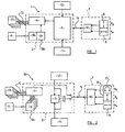
- the first safety system 1 comprises a control unit 2 which has a processor 3.
- the processor 3 is, as discussed above, operable to apply a decision algorithm to signals received from sensors (described below), to determine from these signals whether a crash situation has occurred. Such algorithms are known in the art.
- the control unit 2 further comprises an ignition circuit 4, which is operable to send an actuation command (in this case in the form of an ignition energy pulse) to a safety device of the vehicle, for instance an air-bag, as will be described in more detail below.
- the ignition circuit 4 is connected to one or more substantial capacitors 5a, which are charged with sufficient energy to activate the safety device, and will transmit of the stored energy to the safety device upon receipt of a trigger signal from the processor 3.
- the ignition energy could be taken directly from the vehicle battery, although the battery may become disconnected from the safety arrangement 1, which could result in a failure of the safety device to deploy.
- control unit 2 comprises a voltage regulator 5b, which receives power from the vehicle battery 6, or from an alternative power source, and regulates the voltage for charging the capacitors but could also provide power to the processor 3, and other components of the first safety system 1.
- control unit 2 will be relatively large and heavy, particularly due to the presence of the capacitors and the ignition circuit 4, which normally comprises two switches for each safety device. The switches are respectively closed in response to an arming signal and to the trigger signal.
- the safety system 1 further comprises a sensor unit 7, which comprises a pair of accelerometers 8,9, one of which is orientated so as to measure longitudinal acceleration a x of the vehicle, and the other of which is orientated to measure lateral acceleration a y of the vehicle.
- the sensor unit 7 comprises a signal processor 10, which receives outputs from the accelerometers 8,9 and manipulates the data to be in a suitable form for feeding to the processor 3 of the central unit 2.
- Left and right sensors 11, 12 (which may also be accelerometers) are also provided, separately from the sensor unit 7, and the left and right sensors 11,12 are configured to be located on respective left and right hand sides of the vehicle to provide additional information that may be useful in determining whether or not the vehicle has encountered a crash situation, or in providing information on the type of crash that has occurred.
- the safety system 1 also comprises one or more actuators 13, in the form (in this example) of squibs or other devices such as relays which, upon activation thereof may, by way of example, inflate air-bags and release belt pretensioners.
- actuators 13 in the form (in this example) of squibs or other devices such as relays which, upon activation thereof may, by way of example, inflate air-bags and release belt pretensioners.
- the sensor unit 7 is positioned substantially along a central longitudinal line of the vehicle.
- the sensor unit 7 is located on the central tunnel of the vehicle, and in such embodiments the sensor unit 7 may be directly attached by any suitable means to an upper or lower surface of the central tunnel, or to a covering thereof.
- the sensor unit 7 may be located within the cabin of the vehicle.
- control unit 2 which comprises rather heavier components, is located remotely from the sensor unit 7 and indeed may be placed in any suitable location on the vehicle, not necessarily anywhere near the central longitudinal line thereof (e.g. on a different part of the tunnel or behind the dashboard).
- the control unit 2 communicates with the sensor unit 7 over a sensor communication line 14, which may take any suitable form.
- the remote location of the control unit 2 from the sensor unit 7 means that it is not necessary to house the control unit 2 in the central tunnel of the vehicle, thus alleviating the difficulty discussed above.
- the control unit 2 is also located remotely from the actuator 13, and communicates therewith over an activation communication line 15.
- the control unit 2 comprises an ignition circuit 4 connected to capacitors 5a charged with sufficient energy to activate the actuator 13 (for instance, to activate one or more ignitors to ignite the squibs), and in this embodiment the activation communication line 15 may simply comprise a power line, with the control unit 2 initiating activation of the actuator 13 by discharging the capacitors along the power line.
- FIG. 2 shows a second safety system 16, the system embodying the present invention.
- Common components between the first safety system 1 discussed above and the second safety system 16 are designated by like reference numerals.
- the processing unit 3 in the control unit 2 receives data from the left and right sensors 11,12, and performs signal processing, the output of which is sent to the signal processor 10, which now implements the main crash algorithm and hence decides whether the safety device is to be deployed.
- the signal processor 10 will, upon receiving a signal from the processing unit 3, perform the crash algorithm, and will (if appropriate) instruct the ignition circuit 4 to send an actuation command to the actuators 13.
- the second safety system 16 also comprises a third sensor 17 in the sensor unit 7, this third sensor 17 being position to allow measurement of movement of the vehicle around the roll axis (angular velocity, ⁇ x ).
- FIG. 3 shows a third safety system 18, components thereof that are in common with the first safety system 1 described above being designated by common reference numerals.
- the third safety system 18 comprises further sensors 19, which measure parameters of the car other than the acceleration thereof.
- the further sensors 19 may detect whether seat belt buckles are engaged, or may otherwise detect the presence of an occupant in a given seat of the vehicle, for instance by the weight exerted on the seat, or may measure the position of the seat or a part thereof (such as the headrest).
- the further sensors 19 may also gather information relating to the speed of the vehicle.
- the information output by the further sensors 19 is passed to the control unit 2 via an information bus 20, which allows communication between the control unit 2 and any other remote crash sensors (for instance the left and right sensors 11,12) and the actuator 13.
- the information gathered by the further sensors 19 allows the processing unit 3 of the control unit 2 to arrive at a more informed decision regarding whether to activate the safety device. For instance, if the further sensors 19 detect that the passenger seat of the vehicle is unoccupied during a crash, the control unit 2 may prevent the triggering of a passenger-side air-bag, since this is unlikely to offer protection to the occupants of the vehicle, and may hinder efforts to leave the vehicle, or remove people from the vehicle, following a crash.
- the sensor unit 7 is provided on a single microchip, and it will be appreciated that this system further reduces the size and mass of the components that are to be located in the central tunnel of the vehicle.
- a fourth safety system 21 is shown.
- the fourth safety system 21 is similar to the third safety system 18, however each safety device is provided with a unit comprising a capacitor 5a, an ignition circuit 4 and an actuator 13, and the information bus 20 continuously transmits power from the control unit 2 to the capacitors and other remote units of the system 21, including for instance the sensor unit 7.
- the bus 20 also transmits the actuation command, now in form of a trigger signal, from the processing unit 3 to the ignition circuits. If an arming switch is used in 4, an arming signal will also be sent.
- the sensor unit could also comprise a vertical accelerometer 22 to measure vertical acceleration a z .
- the present invention provides an improved safety system, providing favourable distribution of components around a vehicle, while improving the accuracy with which a crash situation may be detected.
Landscapes
- Engineering & Computer Science (AREA)
- Mechanical Engineering (AREA)
- Physics & Mathematics (AREA)
- Fluid Mechanics (AREA)
- Air Bags (AREA)
- Superstructure Of Vehicle (AREA)
- Vehicle Body Suspensions (AREA)
- Vehicle Interior And Exterior Ornaments, Soundproofing, And Insulation (AREA)
- Passenger Equipment (AREA)
Claims (20)
- Sicherheitssystem für Fahrzeuge (1), das Folgendes beinhaltet:eine Sensoreinheit (7), die mindestens einen Sensor (8) beinhaltet, der auf eine Beschleunigung anspricht, wobei sich die Sensoreinheit (7) im Wesentlichen an einer mittleren Längslinie des Fahrzeugs befindet;ein Stellglied (13) zum Aktivieren einer Schutzvorrichtung, wobei sich das Stellglied (13) von der Sensoreinheit (7) entfernt befindet; undein Steuergerät (2), das sich von der Sensoreinheit (7) entfernt befindet, wobei das Steuergerät (2) so betrieben werden kann, dass es Informationen von der Sensoreinheit (7) erhält und einen Betätigungsbefehl an das Stellglied (13) überträgt, um die Schutzvorrichtung zu aktivieren, wobei das Steuergerät (2) keine Sensoren beinhaltet, die auf eine Beschleunigung ansprechen, dadurch gekennzeichnet, dass die Sensoreinheit (7) einen Signalprozessor (10) zur Erfassung von Daten, die von den Sensoren (8) der Sensoreinheit gesammelt wurden, umfasst, wobei der Signalprozessor (10) so betrieben wird, dass er einen Crash-Algorithmus durchführt, was bewirkt, dass der Signalprozessor (10) das Steuergerät (2) veranlasst, den Betätigungsbefehl an das Stellglied (13) zu senden.
- Sicherheitssystem nach Anspruch 1, wobei sich die Sensoreinheit (7) an einem zentralen Tunnel des Fahrzeugs befindet.
- Sicherheitssystem nach Anspruch 1 oder 2, wobei die Sensoreinheit (7) mindestens zwei Sensoren (8, 9) beinhaltet, die auf eine Beschleunigung ansprechen, und die so konfiguriert sind, dass sie mindestens die Längs- und Querbeschleunigung des Fahrzeugs messen.
- Sicherheitssystem nach einem beliebigen vorangehenden Anspruch, wobei der mindestens eine Sensor (8, 9), der auf eine Beschleunigung anspricht, so konfiguriert ist, dass er die Vertikalbeschleunigung des Fahrzeugs misst.
- Sicherheitssystem nach einem vorangehenden Anspruch, wobei der Signalprozessor (10) so betrieben wird, dass er die erfassten Daten an das Steuergerät (2) überträgt.
- Sicherheitssystem nach einem beliebigen vorangehenden Anspruch, wobei der Signalprozessor (10) so betrieben wird, dass er Daten von anderen Remote-Sensoren (11, 12) erhält.
- Sicherheitssystem nach einem beliebigen vorangehenden Anspruch, wobei die Sensoreinheit (7) einen oder mehrere Sensoren (17) beinhaltet, die so betrieben werden können, dass sie eine Winkelgeschwindigkeit des Fahrzeugs um eine Längsachse davon misst.
- Ein Sicherheitssystem nach einem beliebigen vorangehenden Anspruch, wobei das Stellglied (13) einen Zünder zum Entzünden einer Ladung zum Aktivieren der Schutzvorrichtung beinhaltet.
- Sicherheitssystem nach einem beliebigen vorangehenden Anspruch, wobei das Steuergerät (2) einen oder mehrere Kondensatoren (5a) beinhaltet, die so konfiguriert sind, dass sie ausreichend Energie speichern, um zu bewirken, dass das Stellglied (13) die Schutzvorrichtung aktiviert.
- Sicherheitssystem nach Anspruch 9, wobei das Entladen eines oder mehrerer Kondensatoren (5a) den Betätigungsbefehl beinhaltet.
- Sicherheitssystem nach einem beliebigen vorangehenden Anspruch, wobei sich das Stellglied (13) in einer Einheit befindet, die außerdem einen Kondensator beinhaltet, der so konfiguriert ist, dass er Energie speichert, um die Schutzvorrichtung zu aktivieren, wobei der Kondensator so entladen wird, dass er die Schutzvorrichtung als Reaktion auf den Betätigungsbefehl aktiviert.
- Sicherheitssystem nach einem beliebigen vorangehenden Anspruch, das außerdem mindestens einen linken, seitlichen Sensor (11) an einer linken Seite des Fahrzeugs und mindestens einen rechten, seitlichen Sensor (12) an einer rechten Seite des Fahrzeugs beinhaltet.
- Sicherheitssystem nach einem beliebigen vorangehenden Anspruch, wobei das Steuergerät (2) an der Hauptbatterie (6) des Fahrzeugs angeschlossen ist und Strom zum Sensorgerät (7) und zum Stellglied (13) bereitstellt.
- Sicherheitssystem nach einem beliebigen vorangehenden Anspruch, wobei die Sensoreinheit (7) ein kleineres Volumen als das des Steuergerätes (2) hat.
- Sicherheitssystem nach Anspruch 14, wobei die Sensoreinheit (7) ein kleineres Volumen als die Hälfte des Volumens des Steuergerätes (2) hat.
- Sicherheitssystem nach einem beliebigen vorangehenden Anspruch, wobei die Sensoreinheit (7) eine kleinere Masse als die Masse des Steuergerätes (2) hat.
- Sicherheitssystem nach Anspruch 16, wobei die Masse der Sensoreinheit (7) niedriger ist als die Hälfte der Masse des Steuergerätes (2).
- Sicherheitssystem nach einem beliebigen vorangehenden Anspruch, wobei die Sensoreinheit (7) auf einem einzelnen Mikrochip bereitgestellt wird.
- Sicherheitssystem nach einem beliebigen vorangehenden Anspruch, wobei die Sensoreinheit (7) einen Prozessor beinhaltet.
- Fahrzeug, das ein Sicherheitssystem (1) nach einem beliebigen vorangehenden Anspruch beinhaltet.
Priority Applications (1)
| Application Number | Priority Date | Filing Date | Title |
|---|---|---|---|
| DE60311501.2T DE60311501T3 (de) | 2002-10-21 | 2003-10-21 | Verbesserungen für eine sicherheitsanordnung für ein fahrzeug oder diese betreffend |
Applications Claiming Priority (5)
| Application Number | Priority Date | Filing Date | Title |
|---|---|---|---|
| GB0224429 | 2002-10-21 | ||
| GB0224429A GB2394584A (en) | 2002-10-21 | 2002-10-21 | Vehicle safety arrangement |
| GB0228054A GB2394586A (en) | 2002-10-21 | 2002-12-02 | A safety arrangement for a vehicle |
| GB0228054 | 2002-12-02 | ||
| PCT/SE2003/001622 WO2004035356A1 (en) | 2002-10-21 | 2003-10-21 | Improvements in or relating to a safety arrangement for a vehicle |
Publications (3)
| Publication Number | Publication Date |
|---|---|
| EP1554162A1 EP1554162A1 (de) | 2005-07-20 |
| EP1554162B1 EP1554162B1 (de) | 2007-01-24 |
| EP1554162B2 true EP1554162B2 (de) | 2014-03-26 |
Family
ID=32109256
Family Applications (1)
| Application Number | Title | Priority Date | Filing Date |
|---|---|---|---|
| EP03754336.0A Expired - Lifetime EP1554162B2 (de) | 2002-10-21 | 2003-10-21 | Verbesserungen für eine sicherheitsanordnung für ein fahrzeug oder diese betreffend |
Country Status (8)
| Country | Link |
|---|---|
| US (1) | US8116947B2 (de) |
| EP (1) | EP1554162B2 (de) |
| JP (1) | JP2006503757A (de) |
| KR (1) | KR101082976B1 (de) |
| AT (1) | ATE352460T1 (de) |
| AU (1) | AU2003272172A1 (de) |
| DE (1) | DE60311501T3 (de) |
| WO (1) | WO2004035356A1 (de) |
Families Citing this family (8)
| Publication number | Priority date | Publication date | Assignee | Title |
|---|---|---|---|---|
| GB2416419B (en) * | 2004-07-19 | 2008-10-15 | Autoliv Dev | Improvements in or relating to an arrangement for triggering a vehicle safety device |
| DE102005011242A1 (de) * | 2005-03-11 | 2006-09-14 | Robert Bosch Gmbh | Sicherheitssystem für Fahrzeuginsassen |
| US8229630B2 (en) | 2008-02-11 | 2012-07-24 | Infineon Technologies Ag | Electronic airbag control unit having an autonomous event data recorder |
| US20100324774A1 (en) * | 2009-06-19 | 2010-12-23 | Robert Bosch Gmbh | Vehicle occupant safety system and method including a seat-back acceleration sensor |
| US9061663B2 (en) | 2010-10-27 | 2015-06-23 | Robert Bosch Gmbh | Trailer sway mitigation using torque vectoring |
| US9235937B1 (en) | 2013-06-05 | 2016-01-12 | Analog Devices, Inc. | Mounting method for satellite crash sensors |
| DE102014202666B4 (de) * | 2014-02-13 | 2024-05-23 | Robert Bosch Gmbh | Verfahren und Vorrichtung zum Auslösen zumindest eines Personenschutzmittels eines Fahrzeugs |
| DE102017207578B4 (de) * | 2017-05-05 | 2019-03-07 | Continental Automotive Gmbh | Verfahren zum Auslösen einer Mehrzahl von Aktoren eines Sicherheitssystems eines Kraftfahrzeugs aus einer Energiequelle |
Citations (7)
| Publication number | Priority date | Publication date | Assignee | Title |
|---|---|---|---|---|
| DE19609290A1 (de) † | 1995-10-26 | 1997-04-30 | Bosch Gmbh Robert | Airbagsystem |
| WO1998006604A1 (de) † | 1996-08-14 | 1998-02-19 | Siemens Aktiengesellschaft | Anordnung zum auslösen von rückhaltemitteln in einem kraftfahrzeug |
| DE19736840A1 (de) † | 1997-08-23 | 1999-02-25 | Volkswagen Ag | Verfahren zur situationsabhängigen Auslösung eines Rückhaltesystems und Rückhaltesystem |
| DE19740019A1 (de) † | 1997-09-11 | 1999-03-25 | Siemens Ag | Einrichtung für den Insassenschutz in einem Kraftfahrzeug |
| DE19945923A1 (de) † | 1998-09-25 | 2000-05-18 | Trw Inc | Verfahren und Vorrichtung zum Abfühlen von Seitenaufprallzusammenstoßzuständen mittels einer erhöhten Sicherugsfunktion |
| DE10015267A1 (de) † | 2000-03-28 | 2001-10-25 | Siemens Ag | Steuervorrichtung für Insassenschutzmittel in einem Kraftfahrzeug |
| DE10114504A1 (de) † | 2001-03-23 | 2002-10-02 | Bosch Gmbh Robert | Verfahren zur Übertragung von Daten von wenigstens einem Sensor zu einem Steuergerät |
Family Cites Families (41)
| Publication number | Priority date | Publication date | Assignee | Title |
|---|---|---|---|---|
| US2365574A (en) | 1943-10-21 | 1944-12-19 | Mcwane Cast Iron Pipe Company | Pipe joint |
| FR2592701B1 (fr) | 1986-01-03 | 1988-07-08 | Pont A Mousson | Joint d'etancheite pour le raccordement de deux elements de canalisation, l'un a bout uni, l'autre a emboitement |
| DE3717427C3 (de) | 1987-05-23 | 1994-09-01 | Deutsche Aerospace | Aufprallsensor für Kraftfahrzeuge |
| DE3816587A1 (de) | 1988-05-16 | 1989-11-23 | Messerschmitt Boelkow Blohm | Einrichtung zur ausloesung einer passiven sicherheitseinrichtung |
| US5202831A (en) | 1991-07-09 | 1993-04-13 | Trw Vehicle Safety Systems Inc. | Method and apparatus for controlling an occupant restraint system using real time vector analysis |
| US5322323A (en) | 1991-12-20 | 1994-06-21 | Toyota Jidosha Kabushiki Kaisha | Collision sensing system for side air bag system |
| DE4324753B4 (de) | 1992-08-25 | 2004-05-06 | Daimlerchrysler Ag | Auslösevorrichtung für eine Sicherheitseinrichtung zum Schutz von Fahrzeuginsassen |
| DE4309827C2 (de) | 1993-03-26 | 1995-12-14 | Daimler Benz Ag | Auslösevorrichtung für eine Sicherheitseinrichtung in einem Fahrzeug, insbesondere für einen Seiten-Airbag |
| US5445412A (en) | 1994-03-07 | 1995-08-29 | Automotive Systems Laboratory, Inc. | Vehicle impact detection system |
| GB2292126B (en) | 1994-08-11 | 1997-12-17 | Rover Group | A motor vehicle |
| GB2293681B (en) | 1994-09-29 | 1998-08-12 | Autoliv Dev | Improvements in or relating to a safety arrangement |
| WO1996027514A1 (en) | 1995-03-07 | 1996-09-12 | Sensor Technology Co., Ltd. | Collision detection device |
| FR2732286B1 (fr) | 1995-03-31 | 1997-06-13 | Davey Bickford | Dispositif de securite d'un vehicule |
| DE19520608A1 (de) | 1995-06-06 | 1996-12-12 | Siemens Ag | Steueranordnung zur Auslösung eines Rückhaltemittels in einem Fahrzeug bei einem Seitenaufprall |
| US5826902A (en) | 1996-01-22 | 1998-10-27 | Trw Inc. | Method and apparatus for sensing impact crash conditions with safing function |
| EP0883527B1 (de) * | 1996-03-08 | 1999-10-13 | Siemens Aktiengesellschaft | Anordnung zum steuern eines rückhaltemoduls, insbesondere für ein kraftfahrzeug |
| JPH09315265A (ja) | 1996-03-28 | 1997-12-09 | Aisin Seiki Co Ltd | 車両の乗員保護装置 |
| EP0806594A1 (de) | 1996-04-30 | 1997-11-12 | Teruaki Masuoka | O-Ring mit einem multi-lobularen Querschnitt |
| US5935182A (en) | 1996-09-24 | 1999-08-10 | Trw Inc. | Method and apparatus for discriminating a vehicle crash using virtual sensing |
| DE19645952C2 (de) | 1996-11-07 | 1998-09-03 | Siemens Ag | Steueranordnung für ein Rückhaltemittel in einem Kraftfahrzeug |
| US6145389A (en) * | 1996-11-12 | 2000-11-14 | Ebeling; W. H. Carl | Pedometer effective for both walking and running |
| DE19651123C1 (de) * | 1996-12-09 | 1998-06-18 | Siemens Ag | Steuervorrichtung in einem Kraftfahrzeug |
| US5950973A (en) * | 1997-04-21 | 1999-09-14 | Delco Electronics | Housing mounting system |
| JP3444344B2 (ja) * | 1997-09-25 | 2003-09-08 | マツダ株式会社 | 車両のエアバッグ装置 |
| US5928300A (en) | 1997-10-30 | 1999-07-27 | Simula Inc. | Three-axis aircraft crash sensing system |
| US6111313A (en) | 1998-01-12 | 2000-08-29 | Lsi Logic Corporation | Integrated circuit package having a stiffener dimensioned to receive heat transferred laterally from the integrated circuit |
| JP3906566B2 (ja) | 1998-06-10 | 2007-04-18 | 株式会社デンソー | 車両用乗員保護システムのための衝突判定装置 |
| DE10085025T1 (de) | 1999-09-27 | 2002-09-26 | Visteon Global Tech Inc | Aufprallsensoraufbau und Verfahren zur Montage des Aufbaus in einem Fahrzeug |
| US6296273B1 (en) * | 2000-02-22 | 2001-10-02 | David G. Lewallen | Automobile airbag deactivation system |
| JP4152061B2 (ja) | 2000-05-15 | 2008-09-17 | 日産自動車株式会社 | 乗物用乗員拘束装置 |
| US6249730B1 (en) | 2000-05-19 | 2001-06-19 | Trw, Inc. | Vehicle occupant protection system and method utilizing Z-axis central safing |
| US6522992B1 (en) * | 2000-05-24 | 2003-02-18 | American Gnc Corporation | Core inertial measurement unit |
| US20020106526A1 (en) | 2000-06-05 | 2002-08-08 | Satoru Kuramoto | Seal member |
| JP2001355733A (ja) | 2000-06-12 | 2001-12-26 | Toyota Industries Corp | ハウジング接合部のシール装置 |
| US6459366B1 (en) * | 2000-07-12 | 2002-10-01 | Trw Inc. | System and method for controlling an actuatable occupant protection device |
| US6682094B1 (en) | 2000-08-25 | 2004-01-27 | Ford Global Technologies, Llc | Restraint system |
| US6553295B1 (en) | 2000-10-24 | 2003-04-22 | Ford Global Technologies, Inc. | System for sensing a side impact collision |
| US6529811B2 (en) | 2001-03-01 | 2003-03-04 | Automotive Systems Laboratory, Inc. | Vehicle rollover detection system |
| JP3904139B2 (ja) | 2001-03-30 | 2007-04-11 | スズキ株式会社 | センサーの取付構造 |
| US6529810B2 (en) | 2001-04-09 | 2003-03-04 | Trw Inc. | Method and apparatus for controlling an actuatable restraining device using switched thresholds based on transverse acceleration |
| US6776435B2 (en) | 2001-04-09 | 2004-08-17 | Trw Inc. | Method and apparatus for controlling an actuatable restraining device using switched thresholds based on crush zone sensors |
-
2003
- 2003-10-21 EP EP03754336.0A patent/EP1554162B2/de not_active Expired - Lifetime
- 2003-10-21 DE DE60311501.2T patent/DE60311501T3/de not_active Expired - Lifetime
- 2003-10-21 AT AT03754336T patent/ATE352460T1/de not_active IP Right Cessation
- 2003-10-21 US US10/531,860 patent/US8116947B2/en not_active Expired - Lifetime
- 2003-10-21 WO PCT/SE2003/001622 patent/WO2004035356A1/en not_active Ceased
- 2003-10-21 AU AU2003272172A patent/AU2003272172A1/en not_active Abandoned
- 2003-10-21 KR KR1020057006858A patent/KR101082976B1/ko not_active Expired - Fee Related
- 2003-10-21 JP JP2005501371A patent/JP2006503757A/ja active Pending
Patent Citations (9)
| Publication number | Priority date | Publication date | Assignee | Title |
|---|---|---|---|---|
| US6095554A (en) † | 1995-06-15 | 2000-08-01 | Trw Inc. | Method and apparatus for sensing side impact crash conditions with an enhanced safing function |
| DE19609290A1 (de) † | 1995-10-26 | 1997-04-30 | Bosch Gmbh Robert | Airbagsystem |
| WO1998006604A1 (de) † | 1996-08-14 | 1998-02-19 | Siemens Aktiengesellschaft | Anordnung zum auslösen von rückhaltemitteln in einem kraftfahrzeug |
| US6390498B1 (en) † | 1996-08-14 | 2002-05-21 | Siemens Aktiengesellschaft | Configuration for triggering restraining devices in a motor vehicle |
| DE19736840A1 (de) † | 1997-08-23 | 1999-02-25 | Volkswagen Ag | Verfahren zur situationsabhängigen Auslösung eines Rückhaltesystems und Rückhaltesystem |
| DE19740019A1 (de) † | 1997-09-11 | 1999-03-25 | Siemens Ag | Einrichtung für den Insassenschutz in einem Kraftfahrzeug |
| DE19945923A1 (de) † | 1998-09-25 | 2000-05-18 | Trw Inc | Verfahren und Vorrichtung zum Abfühlen von Seitenaufprallzusammenstoßzuständen mittels einer erhöhten Sicherugsfunktion |
| DE10015267A1 (de) † | 2000-03-28 | 2001-10-25 | Siemens Ag | Steuervorrichtung für Insassenschutzmittel in einem Kraftfahrzeug |
| DE10114504A1 (de) † | 2001-03-23 | 2002-10-02 | Bosch Gmbh Robert | Verfahren zur Übertragung von Daten von wenigstens einem Sensor zu einem Steuergerät |
Non-Patent Citations (2)
| Title |
|---|
| "Chambers science and technology dictionary", 1988, W&R CHAMBERS LTD. AND CAMBRIDGE UNIVERSITY PRESS, NEW YORK, pages: 783 † |
| RONALD K. JURGEN: "Automotive Electronics Handbook", vol. 2, 1999, MCGRAW-HILL † |
Also Published As
| Publication number | Publication date |
|---|---|
| KR20050073569A (ko) | 2005-07-14 |
| DE60311501D1 (de) | 2007-03-15 |
| DE60311501T3 (de) | 2014-07-03 |
| EP1554162B1 (de) | 2007-01-24 |
| EP1554162A1 (de) | 2005-07-20 |
| KR101082976B1 (ko) | 2011-11-11 |
| US8116947B2 (en) | 2012-02-14 |
| DE60311501T2 (de) | 2007-05-16 |
| US20060108781A1 (en) | 2006-05-25 |
| WO2004035356A1 (en) | 2004-04-29 |
| JP2006503757A (ja) | 2006-02-02 |
| ATE352460T1 (de) | 2007-02-15 |
| AU2003272172A1 (en) | 2004-05-04 |
Similar Documents
| Publication | Publication Date | Title |
|---|---|---|
| EP0616926B1 (de) | Verfahren und Vorrichtung zum Rückhalten eines Insassen während eines Seitenaufpralls | |
| US5071160A (en) | Passenger out-of-position sensor | |
| US5746444A (en) | Method and apparatus for single point sensing of front and side impact crash conditions | |
| US6113138A (en) | Control device in a motor vehicle | |
| US5484166A (en) | Method and apparatus for providing a deployment signal for a vehicle occupant restraint device during a side impact crash | |
| EP0689967A1 (de) | Verfahren und Vorrichtung zum Erkennen eines entgegen der Fahrtrichtung ausgerichteten Kindersicherheitssitzes | |
| EP1467897B1 (de) | Verfahren und vorrichtung zur bestimmung der entfaltung einer sicherheitsrückhaltevorrichtung in einem insassenrückhaltesystem | |
| KR20000022153A (ko) | 차량 안전 장치용 콘트롤러 | |
| KR100663794B1 (ko) | 향상된 오용 한계를 갖는 대칭 및 비대칭 충돌 이벤트를결정하기 위한 방법 및 장치 | |
| EP1554162B2 (de) | Verbesserungen für eine sicherheitsanordnung für ein fahrzeug oder diese betreffend | |
| JPH0656000A (ja) | 衝突検出装置 | |
| EP0957013B1 (de) | Zündsteuerungsystem für ein passives Sicherheitssystem mit miteinander kommunizierenden Airbag- und Überrollsteuerungen | |
| JP4424183B2 (ja) | エアバッグ展開制御装置、エアバッグ展開制御方法 | |
| US7744123B2 (en) | Method and apparatus for controlling an actuatable restraining device using XY side satellite accelerometers | |
| US8118130B2 (en) | Method and apparatus for controlling an actuatable restraining device using XY crush-zone satellite accelerometers | |
| GB2394586A (en) | A safety arrangement for a vehicle | |
| JP3951426B2 (ja) | 車両用乗員保護装置 | |
| US6591932B1 (en) | Sensing system for vehicle passive restrants | |
| JPH0655993A (ja) | 車両用エアバッグ作動制御装置 | |
| GB2372862A (en) | A distributed vehicle occupant restraint system | |
| EP1049607B1 (de) | Sicherheitssystem für fahrzeuge | |
| WO2001032475A1 (en) | Improvements in or relating to a control system | |
| Mattes | Occupant protection systems | |
| JP2000203371A (ja) | エアバッグ衝突判定システム |
Legal Events
| Date | Code | Title | Description |
|---|---|---|---|
| PUAI | Public reference made under article 153(3) epc to a published international application that has entered the european phase |
Free format text: ORIGINAL CODE: 0009012 |
|
| 17P | Request for examination filed |
Effective date: 20050415 |
|
| AK | Designated contracting states |
Kind code of ref document: A1 Designated state(s): AT BE BG CH CY CZ DE DK EE ES FI FR GB GR HU IE IT LI LU MC NL PT RO SE SI SK TR |
|
| AX | Request for extension of the european patent |
Extension state: AL LT LV MK |
|
| DAX | Request for extension of the european patent (deleted) | ||
| GRAP | Despatch of communication of intention to grant a patent |
Free format text: ORIGINAL CODE: EPIDOSNIGR1 |
|
| GRAS | Grant fee paid |
Free format text: ORIGINAL CODE: EPIDOSNIGR3 |
|
| GRAA | (expected) grant |
Free format text: ORIGINAL CODE: 0009210 |
|
| AK | Designated contracting states |
Kind code of ref document: B1 Designated state(s): AT BE BG CH CY CZ DE DK EE ES FI FR GB GR HU IE IT LI LU MC NL PT RO SE SI SK TR |
|
| PG25 | Lapsed in a contracting state [announced via postgrant information from national office to epo] |
Ref country code: LI Free format text: LAPSE BECAUSE OF FAILURE TO SUBMIT A TRANSLATION OF THE DESCRIPTION OR TO PAY THE FEE WITHIN THE PRESCRIBED TIME-LIMIT Effective date: 20070124 Ref country code: CH Free format text: LAPSE BECAUSE OF FAILURE TO SUBMIT A TRANSLATION OF THE DESCRIPTION OR TO PAY THE FEE WITHIN THE PRESCRIBED TIME-LIMIT Effective date: 20070124 Ref country code: DK Free format text: LAPSE BECAUSE OF FAILURE TO SUBMIT A TRANSLATION OF THE DESCRIPTION OR TO PAY THE FEE WITHIN THE PRESCRIBED TIME-LIMIT Effective date: 20070124 Ref country code: SI Free format text: LAPSE BECAUSE OF FAILURE TO SUBMIT A TRANSLATION OF THE DESCRIPTION OR TO PAY THE FEE WITHIN THE PRESCRIBED TIME-LIMIT Effective date: 20070124 Ref country code: AT Free format text: LAPSE BECAUSE OF FAILURE TO SUBMIT A TRANSLATION OF THE DESCRIPTION OR TO PAY THE FEE WITHIN THE PRESCRIBED TIME-LIMIT Effective date: 20070124 Ref country code: NL Free format text: LAPSE BECAUSE OF FAILURE TO SUBMIT A TRANSLATION OF THE DESCRIPTION OR TO PAY THE FEE WITHIN THE PRESCRIBED TIME-LIMIT Effective date: 20070124 Ref country code: FI Free format text: LAPSE BECAUSE OF FAILURE TO SUBMIT A TRANSLATION OF THE DESCRIPTION OR TO PAY THE FEE WITHIN THE PRESCRIBED TIME-LIMIT Effective date: 20070124 |
|
| REG | Reference to a national code |
Ref country code: GB Ref legal event code: FG4D |
|
| REG | Reference to a national code |
Ref country code: CH Ref legal event code: EP |
|
| REG | Reference to a national code |
Ref country code: IE Ref legal event code: FG4D |
|
| REF | Corresponds to: |
Ref document number: 60311501 Country of ref document: DE Date of ref document: 20070315 Kind code of ref document: P |
|
| PG25 | Lapsed in a contracting state [announced via postgrant information from national office to epo] |
Ref country code: SE Free format text: LAPSE BECAUSE OF FAILURE TO SUBMIT A TRANSLATION OF THE DESCRIPTION OR TO PAY THE FEE WITHIN THE PRESCRIBED TIME-LIMIT Effective date: 20070424 |
|
| PG25 | Lapsed in a contracting state [announced via postgrant information from national office to epo] |
Ref country code: BG Free format text: LAPSE BECAUSE OF EXPIRATION OF PROTECTION Effective date: 20070425 |
|
| PG25 | Lapsed in a contracting state [announced via postgrant information from national office to epo] |
Ref country code: ES Free format text: LAPSE BECAUSE OF FAILURE TO SUBMIT A TRANSLATION OF THE DESCRIPTION OR TO PAY THE FEE WITHIN THE PRESCRIBED TIME-LIMIT Effective date: 20070505 |
|
| PG25 | Lapsed in a contracting state [announced via postgrant information from national office to epo] |
Ref country code: PT Free format text: LAPSE BECAUSE OF FAILURE TO SUBMIT A TRANSLATION OF THE DESCRIPTION OR TO PAY THE FEE WITHIN THE PRESCRIBED TIME-LIMIT Effective date: 20070625 |
|
| REG | Reference to a national code |
Ref country code: CH Ref legal event code: PL |
|
| NLV1 | Nl: lapsed or annulled due to failure to fulfill the requirements of art. 29p and 29m of the patents act | ||
| ET | Fr: translation filed | ||
| PLBI | Opposition filed |
Free format text: ORIGINAL CODE: 0009260 |
|
| 26 | Opposition filed |
Opponent name: ROBERT BOSCH GMBH Effective date: 20071011 |
|
| PG25 | Lapsed in a contracting state [announced via postgrant information from national office to epo] |
Ref country code: SK Free format text: LAPSE BECAUSE OF FAILURE TO SUBMIT A TRANSLATION OF THE DESCRIPTION OR TO PAY THE FEE WITHIN THE PRESCRIBED TIME-LIMIT Effective date: 20070124 |
|
| PLAX | Notice of opposition and request to file observation + time limit sent |
Free format text: ORIGINAL CODE: EPIDOSNOBS2 |
|
| PG25 | Lapsed in a contracting state [announced via postgrant information from national office to epo] |
Ref country code: BE Free format text: LAPSE BECAUSE OF FAILURE TO SUBMIT A TRANSLATION OF THE DESCRIPTION OR TO PAY THE FEE WITHIN THE PRESCRIBED TIME-LIMIT Effective date: 20070124 Ref country code: RO Free format text: LAPSE BECAUSE OF FAILURE TO SUBMIT A TRANSLATION OF THE DESCRIPTION OR TO PAY THE FEE WITHIN THE PRESCRIBED TIME-LIMIT Effective date: 20070124 Ref country code: CZ Free format text: LAPSE BECAUSE OF FAILURE TO SUBMIT A TRANSLATION OF THE DESCRIPTION OR TO PAY THE FEE WITHIN THE PRESCRIBED TIME-LIMIT Effective date: 20070124 |
|
| PLAF | Information modified related to communication of a notice of opposition and request to file observations + time limit |
Free format text: ORIGINAL CODE: EPIDOSCOBS2 |
|
| PG25 | Lapsed in a contracting state [announced via postgrant information from national office to epo] |
Ref country code: GR Free format text: LAPSE BECAUSE OF FAILURE TO SUBMIT A TRANSLATION OF THE DESCRIPTION OR TO PAY THE FEE WITHIN THE PRESCRIBED TIME-LIMIT Effective date: 20070425 Ref country code: IT Free format text: LAPSE BECAUSE OF FAILURE TO SUBMIT A TRANSLATION OF THE DESCRIPTION OR TO PAY THE FEE WITHIN THE PRESCRIBED TIME-LIMIT Effective date: 20070124 |
|
| PG25 | Lapsed in a contracting state [announced via postgrant information from national office to epo] |
Ref country code: MC Free format text: LAPSE BECAUSE OF NON-PAYMENT OF DUE FEES Effective date: 20071031 |
|
| PLAF | Information modified related to communication of a notice of opposition and request to file observations + time limit |
Free format text: ORIGINAL CODE: EPIDOSCOBS2 |
|
| GBPC | Gb: european patent ceased through non-payment of renewal fee |
Effective date: 20071021 |
|
| PLBB | Reply of patent proprietor to notice(s) of opposition received |
Free format text: ORIGINAL CODE: EPIDOSNOBS3 |
|
| PG25 | Lapsed in a contracting state [announced via postgrant information from national office to epo] |
Ref country code: IE Free format text: LAPSE BECAUSE OF NON-PAYMENT OF DUE FEES Effective date: 20071022 |
|
| PG25 | Lapsed in a contracting state [announced via postgrant information from national office to epo] |
Ref country code: GB Free format text: LAPSE BECAUSE OF NON-PAYMENT OF DUE FEES Effective date: 20071021 |
|
| PG25 | Lapsed in a contracting state [announced via postgrant information from national office to epo] |
Ref country code: EE Free format text: LAPSE BECAUSE OF FAILURE TO SUBMIT A TRANSLATION OF THE DESCRIPTION OR TO PAY THE FEE WITHIN THE PRESCRIBED TIME-LIMIT Effective date: 20070124 |
|
| PG25 | Lapsed in a contracting state [announced via postgrant information from national office to epo] |
Ref country code: CY Free format text: LAPSE BECAUSE OF FAILURE TO SUBMIT A TRANSLATION OF THE DESCRIPTION OR TO PAY THE FEE WITHIN THE PRESCRIBED TIME-LIMIT Effective date: 20070124 |
|
| PG25 | Lapsed in a contracting state [announced via postgrant information from national office to epo] |
Ref country code: LU Free format text: LAPSE BECAUSE OF NON-PAYMENT OF DUE FEES Effective date: 20071021 |
|
| PG25 | Lapsed in a contracting state [announced via postgrant information from national office to epo] |
Ref country code: HU Free format text: LAPSE BECAUSE OF FAILURE TO SUBMIT A TRANSLATION OF THE DESCRIPTION OR TO PAY THE FEE WITHIN THE PRESCRIBED TIME-LIMIT Effective date: 20070725 Ref country code: TR Free format text: LAPSE BECAUSE OF FAILURE TO SUBMIT A TRANSLATION OF THE DESCRIPTION OR TO PAY THE FEE WITHIN THE PRESCRIBED TIME-LIMIT Effective date: 20070124 |
|
| APBM | Appeal reference recorded |
Free format text: ORIGINAL CODE: EPIDOSNREFNO |
|
| APBP | Date of receipt of notice of appeal recorded |
Free format text: ORIGINAL CODE: EPIDOSNNOA2O |
|
| APAH | Appeal reference modified |
Free format text: ORIGINAL CODE: EPIDOSCREFNO |
|
| APBQ | Date of receipt of statement of grounds of appeal recorded |
Free format text: ORIGINAL CODE: EPIDOSNNOA3O |
|
| APBU | Appeal procedure closed |
Free format text: ORIGINAL CODE: EPIDOSNNOA9O |
|
| PUAH | Patent maintained in amended form |
Free format text: ORIGINAL CODE: 0009272 |
|
| STAA | Information on the status of an ep patent application or granted ep patent |
Free format text: STATUS: PATENT MAINTAINED AS AMENDED |
|
| 27A | Patent maintained in amended form |
Effective date: 20140326 |
|
| AK | Designated contracting states |
Kind code of ref document: B2 Designated state(s): AT BE BG CH CY CZ DE DK EE ES FI FR GB GR HU IE IT LI LU MC NL PT RO SE SI SK TR |
|
| REG | Reference to a national code |
Ref country code: DE Ref legal event code: R102 Ref document number: 60311501 Country of ref document: DE |
|
| REG | Reference to a national code |
Ref country code: DE Ref legal event code: R102 Ref document number: 60311501 Country of ref document: DE Effective date: 20140326 |
|
| REG | Reference to a national code |
Ref country code: FR Ref legal event code: PLFP Year of fee payment: 13 |
|
| REG | Reference to a national code |
Ref country code: FR Ref legal event code: PLFP Year of fee payment: 14 |
|
| REG | Reference to a national code |
Ref country code: FR Ref legal event code: PLFP Year of fee payment: 15 |
|
| REG | Reference to a national code |
Ref country code: FR Ref legal event code: PLFP Year of fee payment: 16 |
|
| REG | Reference to a national code |
Ref country code: DE Ref legal event code: R082 Ref document number: 60311501 Country of ref document: DE Representative=s name: BOEHMERT & BOEHMERT ANWALTSPARTNERSCHAFT MBB -, DE Ref country code: DE Ref legal event code: R081 Ref document number: 60311501 Country of ref document: DE Owner name: VEONEER SWEDEN AB, SE Free format text: FORMER OWNER: AUTOLIV DEVELOPMENT AB, VARGARDA, SE |
|
| PGFP | Annual fee paid to national office [announced via postgrant information from national office to epo] |
Ref country code: DE Payment date: 20191030 Year of fee payment: 17 |
|
| PGFP | Annual fee paid to national office [announced via postgrant information from national office to epo] |
Ref country code: FR Payment date: 20191029 Year of fee payment: 17 |
|
| REG | Reference to a national code |
Ref country code: DE Ref legal event code: R119 Ref document number: 60311501 Country of ref document: DE |
|
| PG25 | Lapsed in a contracting state [announced via postgrant information from national office to epo] |
Ref country code: FR Free format text: LAPSE BECAUSE OF NON-PAYMENT OF DUE FEES Effective date: 20201031 Ref country code: DE Free format text: LAPSE BECAUSE OF NON-PAYMENT OF DUE FEES Effective date: 20210501 |