EP4234367B1 - Verfahren zur steuerung der drehmomentvektorisierung für fahrzeuge - Google Patents
Verfahren zur steuerung der drehmomentvektorisierung für fahrzeuge Download PDFInfo
- Publication number
- EP4234367B1 EP4234367B1 EP22158399.0A EP22158399A EP4234367B1 EP 4234367 B1 EP4234367 B1 EP 4234367B1 EP 22158399 A EP22158399 A EP 22158399A EP 4234367 B1 EP4234367 B1 EP 4234367B1
- Authority
- EP
- European Patent Office
- Prior art keywords
- vehicle
- heavy
- road
- bank angle
- duty vehicle
- Prior art date
- Legal status (The legal status is an assumption and is not a legal conclusion. Google has not performed a legal analysis and makes no representation as to the accuracy of the status listed.)
- Active
Links
Images


Classifications
-
- B—PERFORMING OPERATIONS; TRANSPORTING
- B60—VEHICLES IN GENERAL
- B60W—CONJOINT CONTROL OF VEHICLE SUB-UNITS OF DIFFERENT TYPE OR DIFFERENT FUNCTION; CONTROL SYSTEMS SPECIALLY ADAPTED FOR HYBRID VEHICLES; ROAD VEHICLE DRIVE CONTROL SYSTEMS FOR PURPOSES NOT RELATED TO THE CONTROL OF A PARTICULAR SUB-UNIT
- B60W30/00—Purposes of road vehicle drive control systems not related to the control of a particular sub-unit, e.g. of systems using conjoint control of vehicle sub-units
- B60W30/10—Path keeping
-
- B—PERFORMING OPERATIONS; TRANSPORTING
- B62—LAND VEHICLES FOR TRAVELLING OTHERWISE THAN ON RAILS
- B62D—MOTOR VEHICLES; TRAILERS
- B62D6/00—Arrangements for automatically controlling steering depending on driving conditions sensed and responded to, e.g. control circuits
- B62D6/04—Arrangements for automatically controlling steering depending on driving conditions sensed and responded to, e.g. control circuits responsive only to forces disturbing the intended course of the vehicle, e.g. forces acting transversely to the direction of vehicle travel
-
- B—PERFORMING OPERATIONS; TRANSPORTING
- B62—LAND VEHICLES FOR TRAVELLING OTHERWISE THAN ON RAILS
- B62D—MOTOR VEHICLES; TRAILERS
- B62D6/00—Arrangements for automatically controlling steering depending on driving conditions sensed and responded to, e.g. control circuits
-
- B—PERFORMING OPERATIONS; TRANSPORTING
- B60—VEHICLES IN GENERAL
- B60W—CONJOINT CONTROL OF VEHICLE SUB-UNITS OF DIFFERENT TYPE OR DIFFERENT FUNCTION; CONTROL SYSTEMS SPECIALLY ADAPTED FOR HYBRID VEHICLES; ROAD VEHICLE DRIVE CONTROL SYSTEMS FOR PURPOSES NOT RELATED TO THE CONTROL OF A PARTICULAR SUB-UNIT
- B60W30/00—Purposes of road vehicle drive control systems not related to the control of a particular sub-unit, e.g. of systems using conjoint control of vehicle sub-units
- B60W30/02—Control of vehicle driving stability
-
- B—PERFORMING OPERATIONS; TRANSPORTING
- B60—VEHICLES IN GENERAL
- B60W—CONJOINT CONTROL OF VEHICLE SUB-UNITS OF DIFFERENT TYPE OR DIFFERENT FUNCTION; CONTROL SYSTEMS SPECIALLY ADAPTED FOR HYBRID VEHICLES; ROAD VEHICLE DRIVE CONTROL SYSTEMS FOR PURPOSES NOT RELATED TO THE CONTROL OF A PARTICULAR SUB-UNIT
- B60W30/00—Purposes of road vehicle drive control systems not related to the control of a particular sub-unit, e.g. of systems using conjoint control of vehicle sub-units
- B60W30/18—Propelling the vehicle
- B60W30/18009—Propelling the vehicle related to particular drive situations
-
- B—PERFORMING OPERATIONS; TRANSPORTING
- B62—LAND VEHICLES FOR TRAVELLING OTHERWISE THAN ON RAILS
- B62D—MOTOR VEHICLES; TRAILERS
- B62D6/00—Arrangements for automatically controlling steering depending on driving conditions sensed and responded to, e.g. control circuits
- B62D6/002—Arrangements for automatically controlling steering depending on driving conditions sensed and responded to, e.g. control circuits computing target steering angles for front or rear wheels
- B62D6/003—Arrangements for automatically controlling steering depending on driving conditions sensed and responded to, e.g. control circuits computing target steering angles for front or rear wheels in order to control vehicle yaw movement, i.e. around a vertical axis
-
- B—PERFORMING OPERATIONS; TRANSPORTING
- B62—LAND VEHICLES FOR TRAVELLING OTHERWISE THAN ON RAILS
- B62D—MOTOR VEHICLES; TRAILERS
- B62D9/00—Steering deflectable wheels not otherwise provided for
- B62D9/002—Steering deflectable wheels not otherwise provided for combined with means for differentially distributing power on the deflectable wheels during cornering
-
- B—PERFORMING OPERATIONS; TRANSPORTING
- B60—VEHICLES IN GENERAL
- B60W—CONJOINT CONTROL OF VEHICLE SUB-UNITS OF DIFFERENT TYPE OR DIFFERENT FUNCTION; CONTROL SYSTEMS SPECIALLY ADAPTED FOR HYBRID VEHICLES; ROAD VEHICLE DRIVE CONTROL SYSTEMS FOR PURPOSES NOT RELATED TO THE CONTROL OF A PARTICULAR SUB-UNIT
- B60W2300/00—Indexing codes relating to the type of vehicle
- B60W2300/12—Trucks; Load vehicles
-
- B—PERFORMING OPERATIONS; TRANSPORTING
- B60—VEHICLES IN GENERAL
- B60W—CONJOINT CONTROL OF VEHICLE SUB-UNITS OF DIFFERENT TYPE OR DIFFERENT FUNCTION; CONTROL SYSTEMS SPECIALLY ADAPTED FOR HYBRID VEHICLES; ROAD VEHICLE DRIVE CONTROL SYSTEMS FOR PURPOSES NOT RELATED TO THE CONTROL OF A PARTICULAR SUB-UNIT
- B60W2300/00—Indexing codes relating to the type of vehicle
- B60W2300/14—Tractor-trailers, i.e. combinations of a towing vehicle and one or more towed vehicles, e.g. caravans; Road trains
-
- B—PERFORMING OPERATIONS; TRANSPORTING
- B60—VEHICLES IN GENERAL
- B60W—CONJOINT CONTROL OF VEHICLE SUB-UNITS OF DIFFERENT TYPE OR DIFFERENT FUNCTION; CONTROL SYSTEMS SPECIALLY ADAPTED FOR HYBRID VEHICLES; ROAD VEHICLE DRIVE CONTROL SYSTEMS FOR PURPOSES NOT RELATED TO THE CONTROL OF A PARTICULAR SUB-UNIT
- B60W2530/00—Input parameters relating to vehicle conditions or values, not covered by groups B60W2510/00 or B60W2520/00
-
- B—PERFORMING OPERATIONS; TRANSPORTING
- B60—VEHICLES IN GENERAL
- B60W—CONJOINT CONTROL OF VEHICLE SUB-UNITS OF DIFFERENT TYPE OR DIFFERENT FUNCTION; CONTROL SYSTEMS SPECIALLY ADAPTED FOR HYBRID VEHICLES; ROAD VEHICLE DRIVE CONTROL SYSTEMS FOR PURPOSES NOT RELATED TO THE CONTROL OF A PARTICULAR SUB-UNIT
- B60W2552/00—Input parameters relating to infrastructure
- B60W2552/15—Road slope, i.e. the inclination of a road segment in the longitudinal direction
-
- B—PERFORMING OPERATIONS; TRANSPORTING
- B60—VEHICLES IN GENERAL
- B60W—CONJOINT CONTROL OF VEHICLE SUB-UNITS OF DIFFERENT TYPE OR DIFFERENT FUNCTION; CONTROL SYSTEMS SPECIALLY ADAPTED FOR HYBRID VEHICLES; ROAD VEHICLE DRIVE CONTROL SYSTEMS FOR PURPOSES NOT RELATED TO THE CONTROL OF A PARTICULAR SUB-UNIT
- B60W2720/00—Output or target parameters relating to overall vehicle dynamics
- B60W2720/40—Torque distribution
-
- B—PERFORMING OPERATIONS; TRANSPORTING
- B60—VEHICLES IN GENERAL
- B60W—CONJOINT CONTROL OF VEHICLE SUB-UNITS OF DIFFERENT TYPE OR DIFFERENT FUNCTION; CONTROL SYSTEMS SPECIALLY ADAPTED FOR HYBRID VEHICLES; ROAD VEHICLE DRIVE CONTROL SYSTEMS FOR PURPOSES NOT RELATED TO THE CONTROL OF A PARTICULAR SUB-UNIT
- B60W40/00—Estimation or calculation of non-directly measurable driving parameters for road vehicle drive control systems not related to the control of a particular sub unit, e.g. by using mathematical models
- B60W40/12—Estimation or calculation of non-directly measurable driving parameters for road vehicle drive control systems not related to the control of a particular sub unit, e.g. by using mathematical models related to parameters of the vehicle itself, e.g. tyre models
-
- B—PERFORMING OPERATIONS; TRANSPORTING
- B60—VEHICLES IN GENERAL
- B60Y—INDEXING SCHEME RELATING TO ASPECTS CROSS-CUTTING VEHICLE TECHNOLOGY
- B60Y2300/00—Purposes or special features of road vehicle drive control systems
- B60Y2300/02—Control of vehicle driving stability
Definitions
- the present disclosure relates to systems and methods for providing a lateral steering control assist to compensate for road banking in autonomously driven vehicles or vehicles where a human driver gets assistance. More specifically, embodiments of the invention relate to steering assist techniques using torque vectoring. Although the invention is described mainly with respect to heavy-duty vehicles, the invention is not restricted to this particular type of vehicle but may also be used in other types of vehicles.
- Gravity makes a vehicle move sideways when it is driving on a banked road, i.e., a road angled laterally relative to a longitudinal direction of the vehicle.
- a banked road i.e., a road angled laterally relative to a longitudinal direction of the vehicle.
- this phenomenon is desired as the driver can follow the curvature without having to move the steering wheel as much compared to if there is no banking.
- Straight road sections are often banked as well, e.g., to clear water from the road surface.
- lateral movement due to road banking is not desired.
- the driver must counter steer to stay on track. Since most roads are banked in this way, a driver may have to counter steer for mile after mile, which is undesired. Road banking should also be accounted for in autonomous vehicles following a planned path.
- US 2017/0233001 A1 discloses a method for providing vehicle lateral steering control. Furthermore, document WO2017/095300 A1 discloses the preamble of the independent claims.
- the method comprises: obtaining a road bank angle of a road section the heavy-duty vehicle is about to traverse; obtaining a vehicle model indicative of a vehicle motion response to the road bank angle, where the vehicle model includes the understeer/oversteer gradient; determining, based on the road bank angle and the vehicle model, a first compensation torque for reducing the lateral drift of the heavy-duty vehicle at the road section; and applying the first compensation torque across different wheels of the heavy-duty vehicle to reduce the lateral drift of the heavy-duty vehicle due to the road bank angle.
- the compensation torque is a torque vectoring type of control of the vehicle.
- the non-zero understeer/oversteer gradient makes it possible to use such torque vectoring to compensate for road banking without having to turn the wheels. This results in a more predictable vehicle, one which is less sensitive to disturbances coming from road banking.
- the steering wheel is directly connected to the wheels, turning the wheels to compensate for road banking is particularly noticeable for the driver, which is undesired, especially if the motion is jerky, which is common for feedback types of steering control.
- the method uses a feedforward type of control, which does not directly rely on measurements of the lateral movement of the vehicle, i.e., the disclosed control does not rely on reactive measures to compensate for a lateral drift that has already occurred.
- the disclosed control method is instead proactive by being based on road banking information of an upcoming road section.
- a benefit of such feedforward control is that the performance is less jerky compared to feedback control methods, while at the same time presenting good performance in terms of compensation for the road banking.
- the determination of the first compensation torque is based on reducing a drift in lateral travel of the heavy-duty vehicle at an end of the road section. If an intended vehicle path is to go straight in the longitudinal direction of the vehicle, the lateral travel should be zero. Any deviation from that is considered a drift, which is undesired. However, when the intended vehicle path is to travel along a curve, a non-zero value of lateral travel is desired. In that case, however, there may be some drift from this desired value. Therefore, the first compensation torque can be determined to reduce a difference between the desired lateral travel and a lateral travel that would occur without any torque compensation.
- the determination of the first compensation torque can be based on reducing a drift in lateral velocity and/or a drift in yaw rate of the heavy-duty vehicle during traversal of the road section. In some cases it can be desired or sufficient to minimize drift in lateral velocity and/or a drift in yaw rate.
- the vehicle model models a lateral velocity at a centre of gravity and a yaw rate at the centre of gravity in response to the road bank angle.
- This can, e.g., be a one-track model, which is a relatively simple yet accurate way of modelling a heavy-duty vehicle.
- the understeer/oversteer gradient is based on respective cornering stiffnesses of the axles of the heavy-duty vehicle.
- the cornering stiffnesses can be based on tyre properties of wheels of the heavy-duty vehicle, such as dimensions, tyre construction etc., which are relatively static parameters, or inflation pressure, load etc., which can be relatively dynamic parameters.
- the cornering stiffnesses can also, or alternatively, be based on vehicle roll steer geometries, which is a phenomenon that is common for trucks which can be modelled as cornering stiffness.
- the cornering stiffnesses are determined from vehicle motion measurements of the heavy-duty vehicle when the heavy-duty vehicle has traversed a road section.
- the cornering stiffnesses can at least partly be determined from recent measurements during operation of the vehicle.
- the first compensation torque is determined for a desired lateral motion at an upcoming road section using a vehicle model. Equations used for such determination can be used in a reversed way if actual lateral motion is measured after the vehicle has traversed a section. For example, lateral travel can be obtained using a global navigation satellite system. With the vehicle model, road banking information, and any applied compensation torque, any particular parameter in the vehicle model can be calculated from the measured lateral movement.
- the vehicle motion measurements used for determining the cornering stiffnesses comprise any of road bank angle, lateral travel, lateral velocity, longitudinal velocity, the yaw rate, and the first compensation torque.
- the heavy-duty vehicle comprises a towing unit and at least one towed unit connected by an articulation joint, where the vehicle model models a lateral coupling force at the articulation joint in response to the road bank angle.
- This lateral coupling force introduces lateral drift unless compensated for, which is undesired.
- applying the first compensation torque on the towing vehicle can compensate for unwanted movement due to the lateral coupling force.
- the towed unit comprises driven wheels
- the method further comprises determining, based on the road bank angle and the vehicle model, a second compensation torque for reducing the coupling force at the articulation joint of the heavy-duty vehicle at the road section; and applying the second compensation torque across driven wheels of the towed unit to reduce the coupling force at the articulation joint of the heavy-duty vehicle due to the road bank angle. If the lateral coupling force due to road banking is zeroed or at least reduced, steering control for the towing vehicle could be simplified, in particular the determination of the first compensation torque which would have to account for less disturbances due to road banking.
- the road bank angle is obtained from map data and/or one or more vehicle sensors.
- Vehicle sensors can provide a current bank angle which can be used as an approximation of the bank angle in the upcoming road section or provide bank angle information of upcoming road sections.
- the first compensation torque may be applied to the vehicle for any value of the road bank angle, or it may only be applied if the road bank angle is above a predetermined threshold value. This can reduce any jerking in the motion of the vehicle.
- control unit for reducing a lateral drift of a heavy-duty vehicle due to a road bank angle, where the heavy-duty vehicle is associated with a non-zero understeer/oversteer gradient.
- the control unit comprises: processing circuitry; a network interface coupled to the processing circuitry; and a memory coupled to the processing circuitry.
- the memory comprises machine readable computer program instructions that, when executed by the processing circuitry, causes the control unit to: obtain a road bank angle of a road section the heavy-duty vehicle is about to traverse; obtain a vehicle model indicative of a vehicle motion response to the road bank angle, where the vehicle model includes the understeer/oversteer gradient; determine, based on the road bank angle and the vehicle model, a first compensation torque for reducing the lateral drift of the heavy-duty vehicle at the road section; and apply the first compensation torque across different wheels of the heavy-duty vehicle to reduce the lateral drift of the heavy-duty vehicle due to the road bank angle.
- FIG. 1 schematically illustrates an example heavy-duty vehicle 100 for cargo transport.
- the heavy-duty vehicle comprises a local control unit 110 for, i.a., controlling motion of the vehicle.
- the control unit 110 may implement various types of support systems and systems for vehicle functional safety, such as advanced driver assistance systems (ADAS) and functions for autonomous drive systems (ADS).
- ADAS advanced driver assistance systems
- ADS autonomous drive systems
- the vehicle may be connected 120 to a processing device 130 arranged to perform calculations to assist the vehicle control system comprising the control unit 110.
- the connection 120 is preferably wireless but may also be a wireline connection or a connection via a storage module such as a hard drive or the like.
- a heavy-duty vehicle 100 is taken to be a vehicle designed for the handling and transport of heavier objects or large quantities of cargo.
- a heavy-duty vehicle could be truck as in Figure 1 , or a vehicle combination comprising a truck or towing vehicle configured to tow a trailer unit in a known manner, e.g., by a fifth wheel connection.
- a heavy-duty vehicle could be a vehicle designed for use in construction, mining operations, and the like.
- the invention is described mainly with respect to heavy-duty vehicles, the invention is not restricted to this particular type of vehicle but may also be used in other types of vehicles.
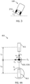
- Figures 2 and 3 show a heavy-duty vehicle 100 traversing a banked road 210, where Figure 2 is a top view and Figure 3 shows the vehicle from the back, i.e., in a longitudinal direction.
- the road has a bank angle ⁇ relative to a horizontal direction, which is in turn is perpendicular relative to the gravity direction.
- Figure 2 shows a start position S of the vehicle.
- the vehicle is about to traverse a road section 211.
- the vehicle will end up at position P B after a time t P due to the road banking if no compensation steering is applied.
- the vehicle would in that case follow a path 230.
- a desired path is to go straight along path 220 to end up at position P after time t P .
- the position P B has lateral travel ⁇ y relative to a longitudinal direction of the starting position of the vehicle.
- These positions can, e.g., represent positions of the centre of gravity of the vehicle.
- drift means a deviation from a desired value.
- the vehicle has lateral travel ⁇ y at the end of the road section if no compensation for road banking is applied.
- lateral travel ⁇ y is zero in the example, which means that the drift in lateral travel is equal to ⁇ y in this case.
- the lateral travel ⁇ y must not always be equal to zero.
- There can be a desired lateral travel ⁇ y D e.g., in a curve.
- the drift in lateral travel would be the difference between ⁇ y D and a travelled lateral distance that would occur if no compensation were.
- the lateral drift can mean a drift in other parameters related to lateral motion, such as yaw rate and lateral velocity, which are discussed in more detail below.
- One way to compensate for the road banking is to counter steer with the wheels.
- the steering wheel is often mechanically linked to the wheels, which results in the steering wheel also moving when counter steering is used to compensate for the disturbance due to road banking.
- Another limitation with such approach is that the sensors that are involved in measuring the lateral movement (disturbance) can cause a jerky sensation in the steering wheel experienced by the driver. There is consequently a need not to have the function engaged all the time, but only if the disturbance is detected as large enough. This, on the other hand, can result in a large drift to occur before it is accounted for.
- the present disclosure relates to using torque vectoring to compensate for lateral drift due to road banking.
- the general idea of torque vectoring is to apply different torques to different wheels to provide an effective torque vector in a vertical direction.
- Torque vectoring can use a differential which can vary the torque to each shaft. If the heavy-duty vehicle is modeled with a one-track model, also commonly called bicycle model, which is discussed in more detail below, applying different torques to the two shafts results in an effective torque vector at the effective bicycle wheel of that axle, which points in a vertical direction. Such vertical torque can be used to control steering of the heavy-duty vehicle. Differential torque can be applied on one or several axles arranged at the front and/or rear of the heavy-duty vehicle. In that case, a torque vector can also be generated across different axles. Furthermore, torque vectoring can also be implemented using independent motors for each wheel, which is common for electrical vehicles.
- Torque vectoring can be achieved with positive or negative torques on the wheels. Using brakes for negative torque is not preferred, however, since they cannot be applied continuously for long time periods. An electric drive with individual control of both wheels of an axle, on the other hand, can continuously provide torque vectoring.
- the present disclosure is directed towards applying a compensation torque across different wheels of the heavy-duty vehicle 100 to reduce a lateral drift of the heavy-duty vehicle due to road banking.
- This compensation torque can be applied using, e.g., the torque vectoring techniques discussed above.
- the disclosed method is particularly relevant for heavy-duty vehicles with a direct mechanical connection between the wheels and the steering wheel, the method is also suitable for vehicles without such direct connection, e.g., vehicles using a drive by wire solution.
- the present disclosure uses a feedforward type of control, which does not directly rely on measurements of the lateral movement of the heavy-duty vehicle, i.e., the disclosed control does not rely on reactive measures to compensate for a lateral drift that has already occurred.
- the disclosed control method is instead proactive by being based on road banking information of an upcoming road section.
- the road bank angle ⁇ can, e.g., be obtained from map data and/or one or more vehicle sensors.
- a benefit of such feedforward control is that the performance is less jerky compared to feedback control methods, while at the same time presenting good performance in terms of compensating for the road banking.
- FIG. 4 shows a vehicle model of the heavy-duty vehicle which can be used in the disclosed method.
- This model is a one-track bicycle model comprising a front wheel 411 and a rear wheel 412.
- the towing vehicle has a mass m and the centre of gravity (COG) 420 between the wheels 411 and 412.
- COG centre of gravity
- the vehicle has a lateral velocity v y , a longitudinal velocity v x , and a vertical yaw rate ⁇ z .
- the front wheel and the rear wheel in the bicycle model are associated with respective lateral linear cornering stiffnesses C F and C R .
- cornering stiffness C ⁇ describes how a lateral force F y,slip depends on a lateral slip angle ⁇ slip , which is the angle between the direction of heading and direction of travel of the vehicle.
- ⁇ slip the angle between the direction of heading and direction of travel of the vehicle.
- the cornering stiffness can be based on tyre properties of wheels 140 of the heavy-duty vehicle 100, such as dimensions, tyre construction (e.g., bias ply or radial ply), tyre treads, cord angles, number of plies etc. These parameters are relatively static. With those parameters given, inflation pressure and load (i.e., vertical force, determined from, i.a., vehicle mass and geometry) are other tyre properties that have a strong influence on the cornering stiffness.
- tyre properties of wheels 140 of the heavy-duty vehicle 100 such as dimensions, tyre construction (e.g., bias ply or radial ply), tyre treads, cord angles, number of plies etc. These parameters are relatively static. With those parameters given, inflation pressure and load (i.e., vertical force, determined from, i.a., vehicle mass and geometry) are other tyre properties that have a strong influence on the cornering stiffness.
- Axle roll steer is a phenomenon that is common for trucks. This phenomenon can be modelled as a change in cornering stiffness when using a one-track model. Thus, it is possible account for roll steer by adjusting the value of C F and C R .
- the cornering stiffnesses of the front wheel and the rear wheel of the bicycle model can be used to calculate an understeer/oversteer gradient K u , which generally is a measure of how much the steering should be adjusted as the speed increases when driving in a circle with fixed radius.
- This vehicle model further assumes that the heavy-duty vehicle 100 has linear tire properties, and that the heavy-duty vehicle has reached steady state, i.e., the time derivatives of the lateral velocity v y , the longitudinal velocity v x , and the yaw rate ⁇ z are zero. It is further assumed that the slip ratio v y / v x is small. These assumptions are often valid except for in transients. The assumptions are typically valid a couple of hundred milliseconds after that any of the conditions has changed.
- the disclosed method applies a first compensation torque T C on the modelled bicycle rear wheel 412.
- torque vectoring for road banking compensation can be achieved in many different ways.
- the two equations further show that the first compensation torque T C also impacts both the yaw rate ⁇ z and the lateral velocity v y .
- the understeer/oversteer gradient is a property of the vehicle and is therefore implicitly or explicitly reflected in the vehicle model used in the disclosed method.
- the vehicle model includes understeer/oversteer gradient K u .
- the parameters in Equations (1) and (2), such as K u , L R , L F , C R , C F can be explicitly used to calculate lateral motion of the heavy-duty vehicle 100.
- the parameters can also be implicitly reflected in the vehicle model by, e.g., measuring how the first compensation torque T C affects the ratio v y / v x . In that case, the factor relating T C to v y / v x can be determined as a whole.
- this factor is the ratio K u / L.
- the non-zero understeer/oversteer gradient is implicitly reflected in the vehicle model.
- model inaccuracies could be accounted for.
- some factor relating the disturbance force F D to the ratio ⁇ z / v x can be determined to implicitly reflect the understeer/oversteer gradient K u in the vehicle model.
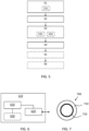
- Figure 5 shows a computer-implemented method for reducing a lateral drift of a heavy-duty vehicle 100 due to a road bank angle ⁇ , where the heavy-duty vehicle is associated with a non-zero understeer/oversteer gradient K u .
- the method comprises: obtaining S1 a road bank angle ⁇ of a road section 211 the heavy-duty vehicle 100 is about to traverse; obtaining S2 a vehicle model indicative of a vehicle motion response to the road bank angle ⁇ , where the vehicle model includes the understeer/oversteer gradient K u ; determining S3, based on the road bank angle ⁇ and the vehicle model, a first compensation torque T C for reducing the lateral drift of the heavy-duty vehicle 100 at the road section 211; and applying S4 the first compensation torque T C across different wheels 140 of the heavy-duty vehicle 100 to reduce the lateral drift of the heavy-duty vehicle due to the road bank angle ⁇ .
- the road bank angle ⁇ can, e.g., be obtained S11 from map data and/or one or more vehicle sensors. For example, if the upcoming road section 211 extends 10 meters in the longitudinal direction, the road bank angle ⁇ can be obtained as an average value of banking in that section from a map.
- a vehicle sensor can provide a current bank angle which can be used as an approximation of the bank angle in the upcoming road section. Examples of such sensors are gyros, accelerometers, slope sensors, and pressure sensors in the suspension system. Other vehicle sensors, such as a camera, lidar, radar, etc., can also provide bank angle information of upcoming road sections.
- the first compensation torque T C may be applied to the vehicle for any value of the road bank angle ⁇ or it may only be applied if the road bank angle ⁇ is above a predetermined threshold value.
- the longitudinal length of the road section 211 can be determined in a number of different ways. It can, e.g., be the longitudinal velocity v x of the heavy-duty vehicle multiplied with a time factor under which the model assumptions are expected to result in accurate motion prediction, which could be a couple hundred milliseconds or so. Alternatively, the longitudinal length of the road section 211 could be some fixed value that results in smooth steering control in most scenarios. A corresponding time can in that case be calculated from the longitudinal velocity v x of the heavy-duty vehicle.
- the length can also be different predetermined values depending on the location. For example, a straight path can be divided into parts with relatively large lengths of the longitudinal section, and curves can be divided into parts with relatively small lengths. Such information can be comprised in the mentioned map data.
- the vehicle model can be the one-track bicycle model discussed in connection to Figure 4A .
- other bicycle models or more general models may be used in the disclosed method to achieve a reduction of lateral drift due to road banking.
- the first compensation torque T C is determined for reducing the lateral drift of the heavy-duty vehicle at the road section 211.
- the reduction of lateral drift can be a reduction of drift in parameters related to lateral motion.
- the determination of the first compensation torque T C can be based on reducing S31 a drift in lateral travel ⁇ y of the heavy-duty vehicle 100 at an end of the road section 211. The end of the road section is where the heavy-duty vehicle has travelled after a configurable time t P .
- T C ⁇ 2 L R 2 C R + 2 L F 2 C F + C R L R ⁇ C F L F L P 2 C R L R ⁇ 2 C F L F + C R + C F L P F D
- the first compensation torque T C is selected such that the lateral travel ( ⁇ y) becomes zero at some preview position P after time t P , which is located a distance L P longitudinally ahead of the vehicle. This is an example how the determination of the first compensation torque T C comprises an explicit calculation.
- this lateral travel ⁇ y must not necessarily be zero. In some cases, moving a lateral distance is desired. For example, when following a corner some non-zero value of ⁇ y is desired. However, there may be some drift from this desired value and correction would in that case be desired. In that case, the first compensation torque T C can be selected in a similar way as above but with the difference that ⁇ y is set the desired value instead of zero, where this desired value is based on information about upcoming road curvature.
- the first compensation torque T C can be selected by neglecting the influence of either the lateral velocity v y and/or the yaw rate ⁇ z , and thereafter determine the first compensation torque T C by zeroing (or suppress) only the other part, i.e., to set either v y or ⁇ z in Equations (1) or (2) to zero and solve for T C .
- This is applicable if the understeer/oversteer gradient K u is non-zero. More generally, however, T C can in this case be solved for a reduced drift from a desired value.
- the determination of the first compensation torque T C can be based on reducing S32 a drift in lateral velocity v y and/or a drift in yaw rate ⁇ z of the heavy-duty vehicle 100 during traversal of the road section 211.
- One benefit of these two ways of determining the first compensation torque is that they do not directly require tuning parameters like L P .
- the length of the road section or duration where the drift in lateral velocity and/or drift in yaw rate is reduced can be predetermined. However, the length or duration are not used directly to calculate the torque.
- these ways of determining the torque can be beneficial if it assumed that the driver is less annoyed by a yaw disturbance than lateral velocity disturbance or vice versa.
- this setup can be suitable if there are other systems in the vehicle reducing one of yaw rate or lateral velocity, such as yaw compensation by active steering compensation.
- the understeer/oversteer gradient K u can be based on respective cornering stiffnesses of the axles of the heavy-duty vehicle 100, and the cornering stiffnesses can be based on tyre parameters, roll steer geometries, or other vehicle parameters.
- the cornering stiffnesses can be directly calculated/determined from such parameters during various test data of the vehicle. For example, cornering stiffnesses can be measured for a vehicle for a number of different states, such as different loads on the tyres, inflation pressures, and other parameters affecting roll steer.
- a current vehicle state can be mapped to a list of states which comprises corresponding cornering stiffnesses. Such mapping can also use interpolation or other curve fitting techniques.
- the first compensation torque T C is determined for a desired lateral motion at an upcoming road section using a vehicle model. Equations used for such determination can be used in a reversed way if actual lateral motion is measured after the vehicle has traversed a section. For example, lateral travel can be obtained using a global navigation satellite system. With the vehicle model, road banking information, and any applied compensation torque, any particular parameter in the vehicle model can be calculated from the measured lateral movement. This can be used to update parameters used in the vehicle model, such as cornering stiffnesses, to improve upcoming steering control.
- various parameters in the vehicle model may be calculated from a measured lateral movement/drift after it has occurred and after a known compensation torque has been applied. This known compensation torque could even be set to zero. This way it is possible to determine some vehicle motion parameters based on measurements of other parameters from the vehicle model. Such updated parameters could then be used for upcoming sections of the road.
- parameters for the vehicle model can either be constant (based on test data or physical vehicle parameters) or adapted while driving.
- the cornering stiffnesses can be determined from vehicle motion measurements of the heavy-duty vehicle 100 when the heavy-duty vehicle has traversed a road section 211.
- the cornering stiffnesses can at least partly be determined from recent measurements during operation.
- the cornering stiffnesses can be calculated from measured vehicle motion parameters such as any of the road bank angle ⁇ , lateral travel ⁇ y, the lateral velocity v y , the longitudinal velocity v x , the yaw rate ⁇ z , and the first compensation torque T C . If such parameters are known, the vehicle model can be used to instead determine the cornering stiffnesses.
- the understeer/oversteer gradient K u could be determined from Equations (1) and (2), which, in turn, can be used to estimate the cornering stiffnesses.
- the cornering stiffnesses can also be determined from other known relations between cornering stiffness and vehicle motion.
- Cornering stiffnesses determined from a road section the vehicle just has traversed can then be used for determination of the compensation torque in an upcoming road section 211 the vehicle is about to traverse. Cornering stiffnesses may also be based on averaging measurements across multiple traversed road sections.
- the road bank angle could be determined based on measurements of other vehicle motion parameters if the cornering stiffnesses are known.
- the heavy-duty vehicle 100 may comprise a towing unit 430 and at least on towed unit 440, such as a semitrailer, connected by an articulation joint 441, where the vehicle model models a lateral coupling force F C at the articulation joint in response to the road bank angle ⁇ .
- the articulation joint may, e.g., be a fifth wheel connection.
- Figure 4B shows an example vehicle model with a towing unit 430 and a towed unit 440, which is similar to the bicycle model in Figure 4A .
- the towed unit comprises an effective wheel 442 and has a centre of gravity 422.
- the articulation joint 441 is arranged at a distance L A from the COG of the towing unit.
- the length of distance from the articulation joint 441 to the wheel 442 is L T .
- This towed unit 440 there is yet another lateral force term F C caused by road banking acting on the towing unit. The term will not act at the COG, but at the articulation joint.
- This lateral coupling force F C results in modified equations for equilibrium of lateral forces and of torques. Using the discussed model assumptions, superposition is possible since it is a linear system. With these modified equations, the first compensation torque T C can be determined to reduce lateral drift in similar ways as discussed in connection to Figure 4A , such as minimizing drift in lateral travel ⁇ y, lateral velocity v y and/or yaw rate ⁇ z .
- the heavy-duty vehicle 100 may comprise a plurality of towed units.
- similar models as in Figure 4B can be used, which would result in other modified equations for equilibrium of lateral forces and of torques, which in turn can be used to determine the first compensation torque T C to reduce lateral drift.
- the towed unit 440 may be equipped with driven wheels that enables torque vectoring, e.g. wheel end motors.
- a second compensation torque T C 2 for the driven axles of the towed unit which reduces or zeroes the lateral coupling force F C due to road banking.
- the disclosed method may comprise determining S5, based on the road bank angle ⁇ and the vehicle model, a second compensation torque T C 2 for reducing the coupling force F C at the articulation joint of the heavy-duty vehicle 100 at the road section 211; and applying S6 the second compensation torque across driven wheels of the towed unit to reduce the coupling force F C at the articulation joint of the heavy-duty vehicle 100 due to the road bank angle ⁇ .
- FIG. 6 schematically illustrates, in terms of a number of functional units, the components of a control unit 110 according to embodiments of the discussions and methods disclosed herein.
- Processing circuitry 610 is provided using any combination of one or more of a suitable central processing unit CPU, multiprocessor, microcontroller, digital signal processor DSP, etc., capable of executing software instructions stored in a computer program product, e.g., in the form of a storage medium 630.
- the processing circuitry 610 may further be provided as at least one application specific integrated circuit ASIC, or field programmable gate array FPGA.
- the processing circuitry 610 is configured to cause the control unit 110 to perform a set of operations, or steps, such as the methods discussed in connection to Figure 5 .
- the storage medium 630 may store the set of operations
- the processing circuitry 610 may be configured to retrieve the set of operations from the storage medium 630 to cause the control unit 110 to perform the set of operations.
- the set of operations may be provided as a set of executable instructions.
- the processing circuitry 610 is thereby arranged to execute methods as herein disclosed.
- the storage medium 630 may also comprise persistent storage, which, for example, can be any single one or combination of magnetic memory, optical memory, solid state memory or even remotely mounted memory.
- the control unit 110 may further comprise an interface 620 for communications with at least one external device, such as the processing device 130.
- the interface 620 may comprise one or more transmitters and receivers, comprising analogue and digital components and a suitable number of ports for wireline or wireless communication.
- the processing circuitry 610 controls the general operation of the control unit 110, e.g., by sending data and control signals to the interface 620 and the storage medium 630, by receiving data and reports from the interface 620, and by retrieving data and instructions from the storage medium 630.
- Other components, as well as the related functionality, of the control node are omitted in order not to obscure the concepts presented herein.
- Figure 7 illustrates a computer readable medium 710 carrying a computer program 720 comprising program code means for performing, e.g., the methods illustrated in Figure 5 , when said program product is run on a computer.
- the computer readable medium and the code means may together form a computer program product 700.
Landscapes
- Engineering & Computer Science (AREA)
- Transportation (AREA)
- Mechanical Engineering (AREA)
- Chemical & Material Sciences (AREA)
- Combustion & Propulsion (AREA)
- Automation & Control Theory (AREA)
- Physics & Mathematics (AREA)
- Mathematical Physics (AREA)
- Control Of Driving Devices And Active Controlling Of Vehicle (AREA)
- Steering Control In Accordance With Driving Conditions (AREA)
Claims (17)
- Computerimplementiertes Verfahren zum Verringern eines seitlichen Abdriftens eines Schwerlastfahrzeugs (100) aufgrund eines Straßenneigungswinkels (<p), wobei das Schwerlastfahrzeug mit einem von Null verschiedenen Untersteuerungs-/Übersteuerungsgradienten (Ku) assoziiert ist, wobei das Verfahren dadurch gekennzeichnet ist, dass es umfasst:Ermitteln (S1) eines Straßenneigungswinkels (<p) eines Straßenabschnitts (211), den das Schwerlastfahrzeug (100) gerade durchfährt;Erhalten (S2) eines Fahrzeugmodells, das eine Fahrzeugbewegungsreaktion auf den Straßenneigungswinkel (<p) anzeigt, wobei das Fahrzeugmodell den Untersteuerungs-/Übersteuerungsgradienten (Ku) enthält; Bestimmen (S3) eines ersten Kompensationsdrehmoments (Tc) auf der Grundlage des Straßenneigungswinkels (<p) und des Fahrzeugmodells zum Reduzieren des seitlichen Drifts des Schwerlastfahrzeugs (100) auf dem Straßenabschnitt (211); undAnwenden (S4) des ersten Kompensationsdrehmoments (Tc) auf verschiedene Räder (140) des Schwerlastfahrzeugs (100), um den seitlichen Drift des Schwerlastfahrzeugs aufgrund des Straßenneigungswinkels (<p) zu reduzieren.
- Verfahren nach Anspruch 1, wobei die Bestimmung des ersten Kompensationsdrehmoments (Tc) auf der Verringerung (S31) eines Drifts in der Seitenfahrt (~y) des Schwerlastfahrzeugs (100) an einem Ende des Straßenabschnitts (211) beruht.
- Verfahren nach Anspruch 1 oder 2, wobei die Bestimmung des ersten Kompensationsdrehmoments (Tc) auf der Verringerung (S32) des Drifts der Seitengeschwindigkeit (vy) und/oder eines Drifts der Gierrate (w2) des Schwerlastfahrzeugs (100) während des Durchfahrens des Straßenabschnitts (211) beruht.
- Verfahren nach einem der vorhergehenden Ansprüche, wobei das Fahrzeugmodell eine Seitengeschwindigkeit (vy) in einem Schwerpunkt (420) und eine Gierrate (w2) in dem Schwerpunkt in Abhängigkeit vom Straßenneigungswinkel (<p) modelliert.
- Verfahren nach einem der vorhergehenden Ansprüche, wobei der Untersteuerungs-/Übersteuerungsgradient (Ku) auf den jeweiligen Kurvensteifigkeiten der Achsen des Schwerlastfahrzeugs (100) basiert.
- Verfahren nach Anspruch 5, wobei die Kurvensteifigkeiten auf den Reifeneigenschaften der Räder (140) des Schwerlastfahrzeugs (100) beruhen.
- Verfahren nach einem der Ansprüche 5 bis 6, wobei die Kurvensteifigkeiten auf der Rolllenkgeometrie des Fahrzeugs beruhen.
- Verfahren nach einem der Ansprüche 5-7, wobei die Kurvensteifigkeiten aus Fahrzeugbewegungsmessungen des Schwerlastfahrzeugs (100) bestimmt werden, wenn das Schwerlastfahrzeug einen Straßenabschnitt (211) befahren hat.
- Verfahren nach Anspruch 8, wobei die Messungen der Fahrzeugbewegung einen der folgenden Werte umfassen: Straßenneigungswinkel (<p), Seitenbewegung (-y), Seitengeschwindigkeit (vy). Längsgeschwindigkeit (vx), Gierrate (w2) und das erste Kompensationsdrehmoment (Tc).
- Verfahren nach einem der vorhergehenden Ansprüche, wobei das Schwerlastfahrzeug (100) eine Zugeinheit (430) und mindestens eine gezogene Einheit (440) umfasst, die durch ein Knickgelenk (441) verbunden sind, wobei das Fahrzeugmodell eine seitliche Kupplungskraft (Fe) an dem Knickgelenk in Reaktion auf den Straßenneigungswinkel (<p) modelliert.
- Verfahren nach Anspruch 10, wobei die gezogene Einheit (440) angetriebene Räder umfasst, wobei das Verfahren ferner umfasst: Bestimmen (SS) eines zweiten Kompensationsdrehmoments (Tc2) auf der Grundlage des Straßenneigungswinkels (<p) und des Fahrzeugmodells zur Verringerung der Kupplungskraft (Fe) am Knickgelenk des Schwerlastfahrzeugs (100) an dem Straßenabschnitt (211); und Aufbringen (86) des zweiten Kompensationsdrehmoments auf die angetriebenen Räder der gezogenen Einheit, um die Kupplungskraft (Fe) am Knickgelenk des Schwerlastfahrzeugs (100) aufgrund des Straßenneigungswinkels (<p) zu verringern.
- Verfahren nach einem der vorhergehenden Ansprüche, wobei das erste Kompensationsdrehmoment (Tc) aufgebracht wird, wenn der Straßenneigungswinkel (<p) über einem vorgegebenen Schwellenwert liegt.
- Verfahren nach einem der vorhergehenden Ansprüche, wobei der Straßenneigungswinkel (<p) aus Kartendaten und/oder einem oder mehreren Fahrzeugsensoren gewonnen wird (811).
- Computerprogramm (720) mit Programmcodemitteln zur Durchführung der Schritte nach einem der Ansprüche 1-13, wenn das Programm auf einem Computer oder einer Verarbeitungsschaltung (710) einer Steuereinheit (110) ausgeführt wird.
- Computerprogrammprodukt (700) mit einem Computerprogramm (720) nach Anspruch 14 und einem computerlesbaren Mittel (710), auf dem das Computerprogramm gespeichert ist.
- Steuereinheit (110) zum Verringern eines seitlichen Abdriftens eines Schwerlastfahrzeugs (100) aufgrund eines Straßenneigungswinkels (<p), wobei das Schwerlastfahrzeug mit einem von Null verschiedenen Untersteuerungs-/Übersteuerungsgradienten (Ku) assoziiert ist. die Steuereinheit dadurch gekennzeichnet ist, dass sie umfasst: eine Verarbeitungsschaltung (610); eine Netzwerkschnittstelle (620), die mit der Verarbeitungsschaltung (610) gekoppelt ist; und einen Speicher (630), der mit der Verarbeitungsschaltung (610) gekoppelt ist, wobei der Speicher maschinenlesbare Computerprogrammanweisungen umfasst, die, wenn sie von der Verarbeitungsschaltung ausgeführt werden, die Steuereinheit (110) veranlassen,:Ermitteln eines Straßenneigungswinkels (<p) eines Straßenabschnitts (211), den das Schwerlastfahrzeug (100) gerade durchfährt;Erhalten eines Fahrzeugmodells, das eine Fahrzeugbewegungsreaktion auf den Straßenneigungswinkel (<p) anzeigt, wobei das Fahrzeugmodell den Untersteuerungs-/Übersteuerungsgradienten (Ku) enthält; Bestimmen eines ersten Kompensationsdrehmoments (Tc) auf der Grundlage des Straßenneigungswinkels (<p) und des Fahrzeugmodells, um den seitlichen Drift des Schwerlastfahrzeugs (100) auf dem Straßenabschnitt (211) zu reduzieren; undAufbringen des ersten Kompensationsdrehmoments (Tc) auf verschiedene Räder (140) des Schwerlastfahrzeugs (100), um den seitlichen Drift des Schwerlastfahrzeugs aufgrund des Straßenneigungswinkels (<p) zu reduzieren.
- Schwerlastfahrzeug (100) umfassend das Steuergerät (110) nach Anspruch 16.
Priority Applications (5)
| Application Number | Priority Date | Filing Date | Title |
|---|---|---|---|
| EP22158399.0A EP4234367B1 (de) | 2022-02-24 | 2022-02-24 | Verfahren zur steuerung der drehmomentvektorisierung für fahrzeuge |
| CN202310098849.6A CN116639181A (zh) | 2022-02-24 | 2023-02-08 | 用于车辆的扭矩矢量控制方法 |
| US18/166,812 US20230264692A1 (en) | 2022-02-24 | 2023-02-09 | Torque vectoring control method for vehicles |
| JP2023018438A JP2023123362A (ja) | 2022-02-24 | 2023-02-09 | 車両のトルクベクタリング制御方法 |
| KR1020230018027A KR20230127149A (ko) | 2022-02-24 | 2023-02-10 | 차량들을 위한 토크 벡터링 제어 방법 |
Applications Claiming Priority (1)
| Application Number | Priority Date | Filing Date | Title |
|---|---|---|---|
| EP22158399.0A EP4234367B1 (de) | 2022-02-24 | 2022-02-24 | Verfahren zur steuerung der drehmomentvektorisierung für fahrzeuge |
Publications (3)
| Publication Number | Publication Date |
|---|---|
| EP4234367A1 EP4234367A1 (de) | 2023-08-30 |
| EP4234367B1 true EP4234367B1 (de) | 2024-11-20 |
| EP4234367C0 EP4234367C0 (de) | 2024-11-20 |
Family
ID=80448871
Family Applications (1)
| Application Number | Title | Priority Date | Filing Date |
|---|---|---|---|
| EP22158399.0A Active EP4234367B1 (de) | 2022-02-24 | 2022-02-24 | Verfahren zur steuerung der drehmomentvektorisierung für fahrzeuge |
Country Status (5)
| Country | Link |
|---|---|
| US (1) | US20230264692A1 (de) |
| EP (1) | EP4234367B1 (de) |
| JP (1) | JP2023123362A (de) |
| KR (1) | KR20230127149A (de) |
| CN (1) | CN116639181A (de) |
Families Citing this family (2)
| Publication number | Priority date | Publication date | Assignee | Title |
|---|---|---|---|---|
| JP2025145286A (ja) * | 2024-03-21 | 2025-10-03 | 株式会社ジェイテクト | 連結車両の推定装置、連結車両の制御装置、連結車両の推定方法、および連結車両の推定プログラム |
| CN120056996A (zh) * | 2025-04-22 | 2025-05-30 | 吉林大学 | 一种考虑扭矩矢量控制的辅助漂移控制方法 |
Family Cites Families (4)
| Publication number | Priority date | Publication date | Assignee | Title |
|---|---|---|---|---|
| US8838311B2 (en) * | 2011-06-15 | 2014-09-16 | Kubota Corporation | Vehicle having independently driven and controlled right and left drive wheels |
| DE102011121117B4 (de) * | 2011-12-14 | 2018-02-01 | Audi Ag | Verfahren zur Seitenwindstabilisierung eines Kraftfahrzeugs sowie Kraftfahrzeug umfassend Vorder- und Hinterräder und eine Einrichtung zur Erfassung einer Seitenablage |
| SE539434C2 (en) * | 2015-12-01 | 2017-09-19 | Scania Cv Ab | Method and system for facilitating steering of a vehicle while driving along a road |
| US9731755B1 (en) | 2016-02-16 | 2017-08-15 | GM Global Technology Operations LLC | Preview lateral control for automated driving |
-
2022
- 2022-02-24 EP EP22158399.0A patent/EP4234367B1/de active Active
-
2023
- 2023-02-08 CN CN202310098849.6A patent/CN116639181A/zh active Pending
- 2023-02-09 JP JP2023018438A patent/JP2023123362A/ja active Pending
- 2023-02-09 US US18/166,812 patent/US20230264692A1/en active Pending
- 2023-02-10 KR KR1020230018027A patent/KR20230127149A/ko active Pending
Also Published As
| Publication number | Publication date |
|---|---|
| KR20230127149A (ko) | 2023-08-31 |
| EP4234367A1 (de) | 2023-08-30 |
| US20230264692A1 (en) | 2023-08-24 |
| EP4234367C0 (de) | 2024-11-20 |
| CN116639181A (zh) | 2023-08-25 |
| JP2023123362A (ja) | 2023-09-05 |
Similar Documents
| Publication | Publication Date | Title |
|---|---|---|
| US10399562B2 (en) | Park assist with tire radius consideration | |
| US5523947A (en) | System and method for estimating trailer length | |
| Jujnovich et al. | Path-following steering control for articulated vehicles | |
| EP0360934B1 (de) | Verfahren und Gerät zur Messung relativer Kursänderungen in einem Fahrzeugbordnavigationssystem | |
| US6725140B2 (en) | Method and apparatus for determining lateral velocity of a motor vehicle in closed form for all road and driving conditions | |
| US8437913B2 (en) | Steering pull compensation | |
| US7844383B2 (en) | Sideslip angle estimation apparatus and method and automotive vehicle incorporating the same | |
| Cheng et al. | High-speed optimal steering of a tractor–semitrailer | |
| US20230264692A1 (en) | Torque vectoring control method for vehicles | |
| CN102582626A (zh) | 重型半挂车状态估计方法 | |
| US20170261994A1 (en) | Curb detection for vehicle parking | |
| CN112888608A (zh) | 用于使得车辆遵循期望曲率路径的方法 | |
| US6915193B2 (en) | Method for determining a longitudinal vehicle velocity by compensating individual wheel speeds using pitch attitude | |
| CN111216732B (zh) | 路面摩擦系数的估测方法、装置及车辆 | |
| US11926381B2 (en) | Dynamics-based articulation angle estimator for a vehicle combination | |
| EP4289696A1 (de) | Schwerpunktbestimmungsvorrichtung und -verfahren | |
| Garcia et al. | Design and simulation for path tracking control of a commercial vehicle using MPC | |
| Han et al. | Estimated state-based optimal path planning and control system for lane-keeping of semi-trailer trucks | |
| Akita et al. | Development of 4WS control algorithms for an SUV | |
| KR20210135526A (ko) | 차량 기동 중 차량의 모션 상태를 추정하는 방법 | |
| EP4527718A1 (de) | System und verfahren zur überwachung der gesundheit eines lenksystems | |
| JP2668249B2 (ja) | 車載航行システムにおいて相対方向変化を測定する方法及び装置 | |
| Martini et al. | Lateral control of tractor-trailer vehicles | |
| CA1287401C (en) | Method and apparatus for measuring relative heading changes in a vehicular onboard navigation system | |
| CN117083209A (zh) | 用于确定车辆的车轮的滑移极限值的方法 |
Legal Events
| Date | Code | Title | Description |
|---|---|---|---|
| PUAI | Public reference made under article 153(3) epc to a published international application that has entered the european phase |
Free format text: ORIGINAL CODE: 0009012 |
|
| STAA | Information on the status of an ep patent application or granted ep patent |
Free format text: STATUS: THE APPLICATION HAS BEEN PUBLISHED |
|
| AK | Designated contracting states |
Kind code of ref document: A1 Designated state(s): AL AT BE BG CH CY CZ DE DK EE ES FI FR GB GR HR HU IE IS IT LI LT LU LV MC MK MT NL NO PL PT RO RS SE SI SK SM TR |
|
| STAA | Information on the status of an ep patent application or granted ep patent |
Free format text: STATUS: REQUEST FOR EXAMINATION WAS MADE |
|
| 17P | Request for examination filed |
Effective date: 20240219 |
|
| RBV | Designated contracting states (corrected) |
Designated state(s): AL AT BE BG CH CY CZ DE DK EE ES FI FR GB GR HR HU IE IS IT LI LT LU LV MC MK MT NL NO PL PT RO RS SE SI SK SM TR |
|
| GRAP | Despatch of communication of intention to grant a patent |
Free format text: ORIGINAL CODE: EPIDOSNIGR1 |
|
| STAA | Information on the status of an ep patent application or granted ep patent |
Free format text: STATUS: GRANT OF PATENT IS INTENDED |
|
| INTG | Intention to grant announced |
Effective date: 20240718 |
|
| GRAS | Grant fee paid |
Free format text: ORIGINAL CODE: EPIDOSNIGR3 |
|
| GRAA | (expected) grant |
Free format text: ORIGINAL CODE: 0009210 |
|
| STAA | Information on the status of an ep patent application or granted ep patent |
Free format text: STATUS: THE PATENT HAS BEEN GRANTED |
|
| AK | Designated contracting states |
Kind code of ref document: B1 Designated state(s): AL AT BE BG CH CY CZ DE DK EE ES FI FR GB GR HR HU IE IS IT LI LT LU LV MC MK MT NL NO PL PT RO RS SE SI SK SM TR |
|
| REG | Reference to a national code |
Ref country code: GB Ref legal event code: FG4D |
|
| REG | Reference to a national code |
Ref country code: CH Ref legal event code: EP |
|
| REG | Reference to a national code |
Ref country code: DE Ref legal event code: R096 Ref document number: 602022007783 Country of ref document: DE |
|
| REG | Reference to a national code |
Ref country code: IE Ref legal event code: FG4D |
|
| U01 | Request for unitary effect filed |
Effective date: 20241126 |
|
| U07 | Unitary effect registered |
Designated state(s): AT BE BG DE DK EE FI FR IT LT LU LV MT NL PT RO SE SI Effective date: 20241202 |
|
| U20 | Renewal fee for the european patent with unitary effect paid |
Year of fee payment: 4 Effective date: 20250224 |
|
| PG25 | Lapsed in a contracting state [announced via postgrant information from national office to epo] |
Ref country code: IS Free format text: LAPSE BECAUSE OF FAILURE TO SUBMIT A TRANSLATION OF THE DESCRIPTION OR TO PAY THE FEE WITHIN THE PRESCRIBED TIME-LIMIT Effective date: 20250320 Ref country code: HR Free format text: LAPSE BECAUSE OF FAILURE TO SUBMIT A TRANSLATION OF THE DESCRIPTION OR TO PAY THE FEE WITHIN THE PRESCRIBED TIME-LIMIT Effective date: 20241120 |
|
| PG25 | Lapsed in a contracting state [announced via postgrant information from national office to epo] |
Ref country code: ES Free format text: LAPSE BECAUSE OF FAILURE TO SUBMIT A TRANSLATION OF THE DESCRIPTION OR TO PAY THE FEE WITHIN THE PRESCRIBED TIME-LIMIT Effective date: 20241120 |
|
| PG25 | Lapsed in a contracting state [announced via postgrant information from national office to epo] |
Ref country code: NO Free format text: LAPSE BECAUSE OF FAILURE TO SUBMIT A TRANSLATION OF THE DESCRIPTION OR TO PAY THE FEE WITHIN THE PRESCRIBED TIME-LIMIT Effective date: 20250220 |
|
| PG25 | Lapsed in a contracting state [announced via postgrant information from national office to epo] |
Ref country code: GR Free format text: LAPSE BECAUSE OF FAILURE TO SUBMIT A TRANSLATION OF THE DESCRIPTION OR TO PAY THE FEE WITHIN THE PRESCRIBED TIME-LIMIT Effective date: 20250221 |
|
| PG25 | Lapsed in a contracting state [announced via postgrant information from national office to epo] |
Ref country code: PL Free format text: LAPSE BECAUSE OF FAILURE TO SUBMIT A TRANSLATION OF THE DESCRIPTION OR TO PAY THE FEE WITHIN THE PRESCRIBED TIME-LIMIT Effective date: 20241120 |
|
| PG25 | Lapsed in a contracting state [announced via postgrant information from national office to epo] |
Ref country code: RS Free format text: LAPSE BECAUSE OF FAILURE TO SUBMIT A TRANSLATION OF THE DESCRIPTION OR TO PAY THE FEE WITHIN THE PRESCRIBED TIME-LIMIT Effective date: 20250220 |
|
| PG25 | Lapsed in a contracting state [announced via postgrant information from national office to epo] |
Ref country code: SM Free format text: LAPSE BECAUSE OF FAILURE TO SUBMIT A TRANSLATION OF THE DESCRIPTION OR TO PAY THE FEE WITHIN THE PRESCRIBED TIME-LIMIT Effective date: 20241120 |
|
| PG25 | Lapsed in a contracting state [announced via postgrant information from national office to epo] |
Ref country code: SK Free format text: LAPSE BECAUSE OF FAILURE TO SUBMIT A TRANSLATION OF THE DESCRIPTION OR TO PAY THE FEE WITHIN THE PRESCRIBED TIME-LIMIT Effective date: 20241120 |
|
| PG25 | Lapsed in a contracting state [announced via postgrant information from national office to epo] |
Ref country code: CZ Free format text: LAPSE BECAUSE OF FAILURE TO SUBMIT A TRANSLATION OF THE DESCRIPTION OR TO PAY THE FEE WITHIN THE PRESCRIBED TIME-LIMIT Effective date: 20241120 |
|
| PG25 | Lapsed in a contracting state [announced via postgrant information from national office to epo] |
Ref country code: MC Free format text: LAPSE BECAUSE OF FAILURE TO SUBMIT A TRANSLATION OF THE DESCRIPTION OR TO PAY THE FEE WITHIN THE PRESCRIBED TIME-LIMIT Effective date: 20241120 |
|
| PLBE | No opposition filed within time limit |
Free format text: ORIGINAL CODE: 0009261 |
|
| STAA | Information on the status of an ep patent application or granted ep patent |
Free format text: STATUS: NO OPPOSITION FILED WITHIN TIME LIMIT |
|
| REG | Reference to a national code |
Ref country code: CH Ref legal event code: PL |
|
| PG25 | Lapsed in a contracting state [announced via postgrant information from national office to epo] |
Ref country code: CH Free format text: LAPSE BECAUSE OF NON-PAYMENT OF DUE FEES Effective date: 20250228 |
|
| 26N | No opposition filed |
Effective date: 20250821 |