EP2631404A2 - Tor - Google Patents
Tor Download PDFInfo
- Publication number
- EP2631404A2 EP2631404A2 EP13155913.0A EP13155913A EP2631404A2 EP 2631404 A2 EP2631404 A2 EP 2631404A2 EP 13155913 A EP13155913 A EP 13155913A EP 2631404 A2 EP2631404 A2 EP 2631404A2
- Authority
- EP
- European Patent Office
- Prior art keywords
- door
- drive means
- door according
- drive
- door leaf
- Prior art date
- Legal status (The legal status is an assumption and is not a legal conclusion. Google has not performed a legal analysis and makes no representation as to the accuracy of the status listed.)
- Granted
Links
- 239000000463 material Substances 0.000 claims abstract description 3
- 230000005540 biological transmission Effects 0.000 claims description 13
- 238000005553 drilling Methods 0.000 description 4
- 238000009434 installation Methods 0.000 description 2
- 238000004804 winding Methods 0.000 description 2
- 230000004888 barrier function Effects 0.000 description 1
- 230000001419 dependent effect Effects 0.000 description 1
- 230000009365 direct transmission Effects 0.000 description 1
- 230000000694 effects Effects 0.000 description 1
- 238000009413 insulation Methods 0.000 description 1
- 239000010985 leather Substances 0.000 description 1
- 230000002093 peripheral effect Effects 0.000 description 1
Images


Classifications
-
- E—FIXED CONSTRUCTIONS
- E05—LOCKS; KEYS; WINDOW OR DOOR FITTINGS; SAFES
- E05D—HINGES OR SUSPENSION DEVICES FOR DOORS, WINDOWS OR WINGS
- E05D15/00—Suspension arrangements for wings
- E05D15/16—Suspension arrangements for wings for wings sliding vertically more or less in their own plane
- E05D15/165—Details, e.g. sliding or rolling guides
-
- E—FIXED CONSTRUCTIONS
- E05—LOCKS; KEYS; WINDOW OR DOOR FITTINGS; SAFES
- E05F—DEVICES FOR MOVING WINGS INTO OPEN OR CLOSED POSITION; CHECKS FOR WINGS; WING FITTINGS NOT OTHERWISE PROVIDED FOR, CONCERNED WITH THE FUNCTIONING OF THE WING
- E05F15/00—Power-operated mechanisms for wings
- E05F15/60—Power-operated mechanisms for wings using electrical actuators
- E05F15/603—Power-operated mechanisms for wings using electrical actuators using rotary electromotors
- E05F15/665—Power-operated mechanisms for wings using electrical actuators using rotary electromotors for vertically-sliding wings
- E05F15/668—Power-operated mechanisms for wings using electrical actuators using rotary electromotors for vertically-sliding wings for overhead wings
- E05F15/681—Power-operated mechanisms for wings using electrical actuators using rotary electromotors for vertically-sliding wings for overhead wings operated by flexible elongated pulling elements, e.g. belts
- E05F15/684—Power-operated mechanisms for wings using electrical actuators using rotary electromotors for vertically-sliding wings for overhead wings operated by flexible elongated pulling elements, e.g. belts by chains
-
- E—FIXED CONSTRUCTIONS
- E05—LOCKS; KEYS; WINDOW OR DOOR FITTINGS; SAFES
- E05F—DEVICES FOR MOVING WINGS INTO OPEN OR CLOSED POSITION; CHECKS FOR WINGS; WING FITTINGS NOT OTHERWISE PROVIDED FOR, CONCERNED WITH THE FUNCTIONING OF THE WING
- E05F15/00—Power-operated mechanisms for wings
- E05F15/60—Power-operated mechanisms for wings using electrical actuators
- E05F15/603—Power-operated mechanisms for wings using electrical actuators using rotary electromotors
- E05F15/665—Power-operated mechanisms for wings using electrical actuators using rotary electromotors for vertically-sliding wings
- E05F15/668—Power-operated mechanisms for wings using electrical actuators using rotary electromotors for vertically-sliding wings for overhead wings
- E05F15/681—Power-operated mechanisms for wings using electrical actuators using rotary electromotors for vertically-sliding wings for overhead wings operated by flexible elongated pulling elements, e.g. belts
- E05F15/686—Power-operated mechanisms for wings using electrical actuators using rotary electromotors for vertically-sliding wings for overhead wings operated by flexible elongated pulling elements, e.g. belts by cables or ropes
-
- E—FIXED CONSTRUCTIONS
- E05—LOCKS; KEYS; WINDOW OR DOOR FITTINGS; SAFES
- E05Y—INDEXING SCHEME RELATING TO HINGES OR OTHER SUSPENSION DEVICES FOR DOORS, WINDOWS OR WINGS AND DEVICES FOR MOVING WINGS INTO OPEN OR CLOSED POSITION, CHECKS FOR WINGS AND WING FITTINGS NOT OTHERWISE PROVIDED FOR, CONCERNED WITH THE FUNCTIONING OF THE WING
- E05Y2800/00—Details, accessories and auxiliary operations not otherwise provided for
- E05Y2800/20—Combinations of elements
- E05Y2800/205—Combinations of elements forming a unit
-
- E—FIXED CONSTRUCTIONS
- E05—LOCKS; KEYS; WINDOW OR DOOR FITTINGS; SAFES
- E05Y—INDEXING SCHEME RELATING TO HINGES OR OTHER SUSPENSION DEVICES FOR DOORS, WINDOWS OR WINGS AND DEVICES FOR MOVING WINGS INTO OPEN OR CLOSED POSITION, CHECKS FOR WINGS AND WING FITTINGS NOT OTHERWISE PROVIDED FOR, CONCERNED WITH THE FUNCTIONING OF THE WING
- E05Y2800/00—Details, accessories and auxiliary operations not otherwise provided for
- E05Y2800/20—Combinations of elements
- E05Y2800/22—Combinations of elements of not identical elements of the same category, e.g. combinations of not identical springs
-
- E—FIXED CONSTRUCTIONS
- E05—LOCKS; KEYS; WINDOW OR DOOR FITTINGS; SAFES
- E05Y—INDEXING SCHEME RELATING TO HINGES OR OTHER SUSPENSION DEVICES FOR DOORS, WINDOWS OR WINGS AND DEVICES FOR MOVING WINGS INTO OPEN OR CLOSED POSITION, CHECKS FOR WINGS AND WING FITTINGS NOT OTHERWISE PROVIDED FOR, CONCERNED WITH THE FUNCTIONING OF THE WING
- E05Y2900/00—Application of doors, windows, wings or fittings thereof
- E05Y2900/10—Application of doors, windows, wings or fittings thereof for buildings or parts thereof
- E05Y2900/106—Application of doors, windows, wings or fittings thereof for buildings or parts thereof for garages
-
- E—FIXED CONSTRUCTIONS
- E05—LOCKS; KEYS; WINDOW OR DOOR FITTINGS; SAFES
- E05Y—INDEXING SCHEME RELATING TO HINGES OR OTHER SUSPENSION DEVICES FOR DOORS, WINDOWS OR WINGS AND DEVICES FOR MOVING WINGS INTO OPEN OR CLOSED POSITION, CHECKS FOR WINGS AND WING FITTINGS NOT OTHERWISE PROVIDED FOR, CONCERNED WITH THE FUNCTIONING OF THE WING
- E05Y2900/00—Application of doors, windows, wings or fittings thereof
- E05Y2900/10—Application of doors, windows, wings or fittings thereof for buildings or parts thereof
- E05Y2900/13—Application of doors, windows, wings or fittings thereof for buildings or parts thereof characterised by the type of wing
- E05Y2900/132—Doors
Definitions
- the invention relates to a gate with a guided in lateral guides door leaf, which may consist of a one-piece door leaf or multi-part segments or the like.
- Such a door leaf can be transferred manually or by a drive from a closed position to an open position and vice versa.
- at least one revolving drive means is present, which has a load strand and an empty strand.
- a gate with a lateral drive which is designed as a sectional door for closing a building opening.
- the door leaf on opposite sides of the building opening arranged guides for movably guiding the door leaf between one of the building opening releasing and closing the building opening position and with at least one horizontally extending portion, a drive for moving the door leaf.
- the drive comprises a transmission device, which communicates with the door leaf and is arranged transversely to the door leaf off-center of one of the horizontal sections of one of the guides.
- a drive wheel for driving the transmission device via the drive wheel is present so that a load strand and an idle strand are present.
- the axis of rotation of the drive wheel is perpendicular and it is followed by a guide device to the drive wheel, which leads the load and / or the slack in the way that gradually reduces the distance between the load strand and slack side of the drive wheel to the building opening.
- a roller shutter with a door leaf and guides arranged on both sides shows the DE 10 2009 044 492 A1 .
- a roller door has a vertical section and a spiral section, wherein the door leaf in the open state of the roller shutter in non-contact winding layers in the spiral sections is included.
- the roller shutter is characterized in that the drive shaft is arranged in the central region of the spiral sections of the two-sided guides and extends from one gate side to the other.
- a roller door is created whose height is to be reduced in the lintel area while maintaining a low installation depth compared to the prior art.
- To drive a toothed belt is used, which causes endlessly as the endless belt driving the door leaf.
- the object of the invention is to improve a gate, which has a manually or by a drive movable door leaf, to the effect that on the one hand, the production costs are reduced and, secondly, in addition to a simple assembly in operation, a reduction in the Torblattiolo by the Drive means to reduce noise generated.
- a gate which has a door leaf, which is guided in lateral guides and by a drive or manually from a closed position into an open position and vice versa, is driven with a peripheral, at least on one side existing drive means.
- a drive means thus has a load strand and an empty strand.
- Lastrum is the part of the revolving drive means which, for example, has to lift the entire gate weight when opening the gate.
- an empty strand of the part of the drive means is called, which closes to complete the at least once existing, self-contained drive means, virtually the circle of the drive means.
- a lateral drive is used to move the door leaf.
- the drive unit is mounted both laterally and in the middle of a continuous drive shaft.
- a one-sided or even a double-sided drive is present, which is connected by a drive shaft.
- a rotating drive means a simple drive possible.
- a reduction of the required installation space and the drive parts used is achieved.
- the part of the drive means which is connected to the door leaf, as Lasttrum and the part which is not connected to the door leaf is referred to as an empty strand. This means that when the door is opened the door leaf is pulled up through the load passage.
- the drive means is formed with its load strand limb or tooth-shaped or the like in order to transmit such high forces safely.
- the slack side is preferably made of a flat material in the form of a flat belt or a V-belt or a toothed belt, but running on his back, formed.
- Such a design means that the Lasttrum is used to transmit power of the door leaf and the empty strand acts only as a connecting means between the end and the beginning of the load tube.
- the load strand and the slack side are connected by a driver and on the other hand by a lock.
- the driver has been designed so that this example also has rollers that are guided in a lateral profile design.
- a Torblattanitati to the lower side of the door leaf is preferably formed on this driver via a ball connection.
- the drive means is guided within a guide profile and for structure-borne noise reduction there is an insulating insert within the guide profile.
- a tensioning device has been used for automatically generating tension of the drive means within the self-contained drive means.
- Such a jig automatically adjusts itself within a certain range. If this area has arrived at the end of its limit, there is at the same time a sensor element which detects this situation. At the same time, however, this is also to be seen as an indicator that possibly the drive means must be replaced.
- Such a clamping device has been designed as a replaceable unit and consists essentially of a mounting unit having a base floor with lateral bends.
- a two-sided arm is rotatably mounted, which can perform the predetermined, limited stroke via a corresponding guide element in a backdrop.
- a safety device is created, which always ensures that such a connected gate is ready to operate under all circumstances.
- the guided in the backdrop arm is loaded by a spring element so that a one-sided arranged on the arm guide wheel is always employed against the drive means with a load strand.
- Such a door equipped with a drive means of the aforementioned kind can be designed as a lifting gate or sectional door or spiral door or high-speed door or the like.
- a driver 1 of a self-contained drive means 2 is reproduced.
- a load strand 58 and below the driver 1 an empty strand 6 is shown in the upper part of the driver 1.
- Both the load strand 58 is articulated on one side of the driver 1 by a corresponding connection 3 and the slack side 6 is also connected via an attachment 8 with the driver 1.
- the other ends of the slack side 6 and the load shaft 58 are connected to each other via a lock 7.
- a Torblattanitati 5 preferably in the form of a ball joint 54, available.
- This structure of the drive means 2 can be seen very clearly with two different means. It turns out that the load strand 58 enters into a non-positive and positive connection with the drive wheel 19, not shown here, and the empty strand 6 only via a in the FIG. 4 shown in diameter smaller deflection roller 13 than the drive wheel 19, is guided.
- a flat belt may be preferably made of plastic with a corresponding tissue or the like. However, it is also possible to bring here a leather belt or the like for use.
- the drive means 2 is guided so that from the outside no accidental contact can take place.
- a liner 9 which is preferably made of a plastic or the like.
- the insert 9 is preferably selectively connected to the guide profile 10 so as to prevent a direct transmission of the running noise to the resonator of the frames or the like.
- a projection 11 is almost the interior split the guide profile 10, so that even with a quick movement of the door leaf, the mutually running members of the load strand 58 can not come into contact.
- a continuous incision 60 through which a part of the driver 1 protrudes and at the same time establishes the connection to the load strand 58 and the empty strand 6.
- the part that protrudes outwards through the incision is connected to the door leaf via a lever.
- the guide roller 13 can be seen for the return strand 6, which is mounted on a threaded axis 12 within the guide profile 10.
- the insert 9 applies itself within the guide profile 10 to an inner wall thereof.
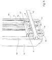
- FIG. 6 an upper part of the door with the drive unit 17 and the drive means 2 becomes visible.
- the drive means 2 is driven in the form of the load shaft 58.
- the load gallery 58 For reasons of clarity, only part of the load gallery 58 has been drawn.
- the clamping device 20 is adjustable via an adjusting means 24 in its position. By means of a deflecting wheel 21, the drive means 2 is thus always kept at tension.
- the drive wheel 19 and a transmission axis 18 8 are driven in this case.
- the tensioning device 20 becomes clear in detail.
- a base bottom 63 are laterally bends 62 of a stamped and bent part visible.
- a link 23 in which a guide element 28 of a two-sided arm 27 engages.
- This arm 27 is mounted in a pivot point 29 so that on the longer arm at the end via an axis 26, the guide wheel 21 is rotatably mounted.
- the other end extending from the pivot point 29 driver 32 acts with a switching element 30, in the form of a switching spring 31, for detecting the proper voltage to the drive means 2, together.
- a spring element 25 is employed against the arm 27 so that a corresponding pressure on the drive means 2 is always maintained by the spring element 25.
- the actuating means 24 On the basic adjustability of the entire clamping device 20 can be influenced by the actuating means 24. So that a sufficient adjustability is given here, located in the drive module according to the FIG. 6 a slot 22.
- FIG. 9 is an exploded view of the FIG. 9 resorted.
- a connecting lever 39 is present. While the Torblattanitati 5 is connected to the driver 1 via the bore 41, at the other end to the connecting lever 39 via preferably executed as a ball joint connection a pivot point 40, which realizes the connection to a transmission lever 44 with the ball joint connection 54.
- the transmission lever 44 is connected and secured within a bore 55 with existing at a bend 47 of the stop plate 36 axis of rotation 42. Through the connection over the Bore 55 thus arises for the transmission lever 44 a two-armed lever, at one end of the connecting lever 39 is fixed and at the other end an adjustment of the connection to the driver 1 has been created.
- the adjustability results from a, guided within a link 45 bush 46 with a threaded bore 54.
- the bushing 46 has lateral surfaces which cooperate within an opening 52 on the stop plate 36 such that the bushing in a bore 56 of a variable slider 48th dips and is pulled over a connecting screw 51 against a guide 49.
- the slider 48 is variable in height.
- the position of the transmission lever 44 is changed at the same time. Due to the adjustability of the adjusting screw 50 thus the point of application for the connecting lever 39 with the driver 1 and the Torblattanitati 5 can be adjusted continuously.
- a link 43 which is aligned with a bore 64 within the guide 49.
- an axle of a roller is introduced, which has not been shown. The role serves to guide the door leaf within the side rail 33rd
Abstract
Description
- Die Erfindung betrifft ein Tor mit einem in seitlichen Führungen geführten Torblatt, das aus einem einteiligen Torblatt oder aus mehrteiligen Segmenten oder dergleichen bestehen kann.
- Ein solches Torblatt kann manuell oder durch einen Antrieb aus einer Schließstellung in eine Öffnungsstellung und umgekehrt überführt werden. Um diese Bewegungen durchführen zu können, ist mindestens ein umlaufendes Antriebsmittel vorhanden, das einen Lasttrum und einen Leertrum aufweist.
- Mit der
DE 10 2009 045 796 A1 ist ein Tor mit einem seitlichen Antrieb bekannt geworden, das als Sektionaltor zum Verschließen einer Gebäudeöffnung ausgebildet ist. Dabei weist das Torblatt an gegenüberliegenden Seiten der Gebäudeöffnung angeordnete Führungen zum beweglichen Führen des Torblattes zwischen einer der Gebäudeöffnung freigebenden und einer der Gebäudeöffnung verschließenden Stellung und mit mindestens einem horizontal verlaufenden Abschnitt, einen Antrieb zum Bewegen des Torblattes auf. Der Antrieb umfasst eine Übertragungseinrichtung, die mit dem Torblatt in Verbindung steht und quer zum Torblatt außermittig einem der horizontalen Abschnitte einer der Führungen zugeordnet angeordnet ist. Dabei ist ein Antriebsrad zum Antreiben der Übertragungseinrichtung über das Antriebsrad so vorhanden, dass ein Lasttrum und ein Leertrum vorhanden sind. Dabei verläuft die Drehachse des Antriebsrads lotrecht und es schließt sich eine Führungseinrichtung an das Antriebsrad an, welches den Last- und/oder den Leertrum in der Art führt, dass sich der Abstand zwischen Lasttrum und Leertrum vom Antriebsrad zur Gebäudeöffnung allmählich verkleinert. - Ein Rolltor mit einem Torblatt und beidseitig angeordneten Führungen zeigt die
DE 10 2009 044 492 A1 . Ein solches Rolltor weist einen Vertikalabschnitt und einen Spiralabschnitt auf, wobei das Torblatt im geöffneten Zustand des Rolltores in berührungsfreien Wickellagen in den Spiralabschnitten aufgenommen ist. Dabei zeichnet sich das Rolltor dadurch aus, dass die Antriebswelle im Zentralbereich der Spiralabschnitte der beidseitigen Führungen angeordnet ist und sich von einer Torseite zur anderen erstreckt. Damit wird ein Rolltor geschaffen, dessen Aufbauhöhe im Torsturzbereich unter Beibehaltung einer geringen Einbautiefe gegenüber dem Stand der Technik reduziert werden soll. Zum Antrieb wird ein Zahnriemen verwendet, der als Endlosriemen umlaufend den Antrieb des Torblattes bewirkt. - Durch die
DE 20 2007 000 460 U1 wird ein Rolltor bekannt, das zu einem mehrlagigen Wickel im Öffnungszustand aufgewickelt wird. Dazu ist seitlich eine Antriebseinheit vorhanden, die mit einer endlos umlaufenden Kette die Bewegung des Rolltores bewirkt. In gleicher Weise ist derDE 692 19 654 T2 eine seitlich umlaufende Kette zum Antrieb des Tores zu entnehmen. - Die Aufgabe der Erfindung besteht darin, ein Tor, welches ein manuell oder durch einen Antrieb bewegbares Torblatt aufweist, dahingehend zu verbessern, dass zum einen die Herstellkosten gesenkt werden und zum anderen neben einer einfachen Montage auch im Betrieb eine Reduzierung der bei der Torblattbewegung durch das Antriebsmittel erzeugten Geräusche zu reduzieren.
- Die Aufgabe der Erfindung wird durch die Merkmale des Anspruchs 1 gelöst. Die Unteransprüche haben dabei weitere Ausgestaltungen und verschiedene Anwendungsmöglichkeiten des Lösungsprinzips zum Inhalt.
- Ein Tor, das ein Torblatt aufweist, welches in seitlichen Führungen geführt wird und durch einen Antrieb oder manuell aus einer Schließlage in eine Öffnungsstellung und umgekehrt überführbar ist, wird mit einem umlaufenden, mindestens auf einer Seite vorhandenem Antriebsmittel angetrieben. Ein derartiges Antriebsmittel hat somit einen Lasttrum und einen Leertrum. Als Lastrum wird der Teil des umlaufenden Antriebsmittels bezeichnet, der beispielsweise beim Öffnen des Tores das gesamte Torgewicht anheben muss. Als Leertrum wird der Teil des Antriebsmittels bezeichnet, der zur Komplettierung des mindestens einmal vorhandenen, in sich geschlossenen Antriebsmittels, quasi den Kreis des Antriebsmittels schließt. Bei einer solchen Ausführung wird z.B. zur Bewegung des Torblattes ein seitlicher Antrieb verwendet. Durch eine derartige Montage ist es möglich, dass bei einem maschinellen Antrieb die Antriebseinheit sowohl seitlich als auch in der Mitte einer durchgehenden Antriebswelle angebracht wird. Bei der Ausführung eines seitlichen Antriebes ist je nach Größe des Tores und seines Aufbaues ein einseitiger oder aber auch ein beidseitiger Antrieb vorhanden, der durch eine Antriebswelle verbunden wird. Somit ist durch die Verwendung eines umlaufenden Antriebsmittels ein einfacher Antrieb möglich. Durch eine derartige Anordnung wird eine Reduzierung des benötigenden Bauraumes und der verwendeten Antriebsteile erreicht. Somit ergibt sich, dass der Teil des Antriebsmittels, der mit dem Torblatt verbunden ist, als Lasttrum und der Teil, der nicht mit dem Torblatt verbunden ist, als Leertrum bezeichnet wird. Dieses bedeutet, dass bei der Öffnungsfahrt das Torblatt durch den Lasttrum hochgezogen wird. Bei der nach der Öffnungsfahrt sich anschließenden Schließfahrt wird durch den Lasttrum wieder nicht das gesamte Gewicht getragen, was bedeutet, dass der Leertrum keinen hohen Belastungen ausgesetzt ist. Diese Tatsache macht sich die Erfindung zu Eigen, indem der Lasttrum und der Leertrum jeweils aus unterschiedlichen Mitteln bestehen. Dabei weist der Lasttrum einen Form- und Kraftschluss mit einem Antriebsrad auf. Der Leertrum weist dagegen einen reinen Formschluss mit einer im unteren Bereich vorhandenen Umlenkrolle auf.
- Dieses hat zur Folge, dass das Antriebsmittel mit seinem Lasttrum glieder- oder zahnförmig oder dergleichen ausgebildet ist, um so hohe Kräfte sicher übertragen zu können. Der Leertrum ist dabei vorzugsweise aus einem flachen Material in Form eines Flachriemen oder eines Keilriemens oder eines Zahnriemens, der aber auf dem Rücken läuft, ausgebildet. Eine solche Ausbildung bedeutet, dass der Lasttrum zur Kraftübertragung des Torblattes eingesetzt wird und der Leertrum nur als Verbindungsmittel zwischen dem Ende und dem Anfang des Lasttrums wirkt. Untereinander sind der Lasttrum und der Leertrum zum einen durch einen Mitnehmer verbunden und andererseits durch ein Schloss. Der Mitnehmer ist dabei so gestaltet worden, dass dieser beispielsweise auch Laufrollen aufweist, die in einer seitlichen Profilausgestaltung geführt werden. Gleichzeitig ist an diesem Mitnehmer vorzugsweise über eine Kugelverbindung eine Torblattanbindung zu der unteren Seite des Torblattes ausgebildet.
- Um bei der Öffnungs- und Schließfahrt die Fahrgeräusche so gering wie möglich zu halten, wird das Antriebsmittel innerhalb eines Führungsprofils geführt und zur Körperschallreduzierung ist dort innerhalb des Führungsprofils eine dämmende Einlage vorhanden.
- Damit ein derartiges Antriebsmittel auch stets mit seinen Zähnen oder Kettengliedern innerhalb des Antriebsrades in Eingriff steht, ist eine Spannvorrichtung zur automatischen Spannungserzeugung des Antriebsmittels innerhalb des in sich geschlossenen Antriebsmittels verwendet worden. Eine solche Spannvorrichtung stellt sich automatisch innerhalb eines bestimmten Bereiches nach. Sollte dieser Bereich am Ende seines Limits angekommen sein, so ist gleichzeitig ein Sensorelement vorhanden, welches diese Situation detektiert. Gleichzeitig ist dieses jedoch auch als Indikator dafür zu sehen, dass möglicherweise das Antriebsmittel ausgetauscht werden muss.
- Eine solche Spannvorrichtung ist dabei als auswechselbare Einheit ausgebildet worden und besteht im Wesentlichen aus einer Montageeinheit, die einen Basisboden mit seitlichen Abwinkelungen aufweist. Auf dem Basisboden ist verdrehbar ein zweiseitiger Arm gelagert, der über ein entsprechendes Führungselement in einer Kulisse den vorgegebenen, begrenzten Hub ausführen kann. Durch diese Maßnahme, in Verbindung mit dem Sensorelement, wird eine Sicherungsvorrichtung geschaffen, die stets dafür Sorge trägt, dass ein solches angeschlossenes Tor auch unter allen Umständen betriebsbereit ist. Der in der Kulisse geführte Arm wird durch ein Federelement so belastet, dass ein einseitig an dem Arm angeordnetes Umlenkrad stets gegen das Antriebsmittel mit einem Lasttrum angestellt ist.
- Ein solches Tor ausgestattet mit einem Antriebsmittel der vorbezeichneten Art kann als Hubtor oder Sektionaltor oder Spiraltor oder Schnelllauftor oder dergleichen ausgebildet sein.
- Weitere Vorteile, Merkmale und Anwendungsmöglichkeiten der vorliegenden Erfindung ergeben sich aus der nachfolgenden Beschreibung in Verbindung mit den in den Zeichnungen dargestellten Ausführungsbeispielen.
- In der Beschreibung, in den Ansprüchen und in der Zeichnung werden die in der unten aufgeführten Liste der Bezugzeichen verwendeten Begriffe und zugeordneten Bezugzeichen verwendet. In der Zeichnung bedeutet:
- Fig. 1
- einen Ausschnitt aus einem Antriebsmittel mit einem Mitnehmer;
- Fig. 2
- wie
Figur 1 , jedoch aus einem anderen Blickwinkel; - Fig. 3
- eine perspektivische Darstellung eines Führungsprofils mit Antriebsmittel;
- Fig. 4
- den unteren Bereich einer Umlenkrolle innerhalb des Führungsprofils;
- Fig. 5
- wie
Figur 4 ; jedoch in einer Schnittdarstellung; - Fig. 6
- ein Antriebsmodul mit einem Antriebsmittel;
- Fig. 7
- eine bevorzugte Ausführungsform einer Spannvorrichtung für das Antriebsmittel;
- Fig. 8
- eine untere Anbindung an das Torblatt;
- Fig. 9
- wie
Figur 8 , jedoch in einer einzelperspektivischen Darstellung; - Fig. 10
- wie
Figur 9 , jedoch aus einem anderen Blickwinkel, und - Fig. 11
- wie
Figur 10 . - In der
Figur 1 wird ein Mitnehmer 1 eines in sich geschlossenen Antriebsmittels 2 wiedergegeben. Dabei ist im oberen Teil des Mitnehmers 1 ein Lasttrum 58 und unterhalb des Mitnehmers 1 ein Leertrum 6 dargestellt. Sowohl der Lasttrum 58 ist an dem Mitnehmer 1 durch eine entsprechende Verbindung 3 einseitig angelenkt und der Leertrum 6 ist über eine Befestigung 8 ebenfalls mit dem Mitnehmer 1 verbunden. Die anderen Enden der Leertrums 6 und des Lasttrums 58 werden über ein Schloss 7 miteinander verbunden. - Innerhalb des Mitnehmers 1 sind Laufrollen 4 gelagert, die dafür sorgen, dass innerhalb eines Führungsprofils 10 eine saubere Führung des Mitnehmers 1 gewährleistet ist. Ferner ist an dem Mitnehmer 1 eine Torblattanbindung 5, vorzugsweise in Form eines Kugelgelenkes 54, vorhanden. In der Darstellung der
Figur 2 kann dieser Aufbau des Antriebsmittels 2 mit zwei unterschiedlichen Mitteln sehr deutlich gesehen werden. Dabei zeigt sich, dass der Lasttrum 58 mit dem hier nicht dargestellten Antriebsrad 19 eine kraft- und formschlüssige Verbindung eingeht und der Leertrum 6 nur über eine in derFigur 4 dargestellte im Durchmesser kleinere Umlenkrolle 13 als das Antriebsrad 19, geführt wird. Ein solcher Flachriemen kann vorzugsweise aus Kunststoff mit einem entsprechenden Gewebe oder dergleichen ausgestattet werden. Es ist jedoch auch möglich, hier einen Lederriemen oder dergleichen zur Anwendung zu bringen. - Innerhalb des Führungsprofils 10 ist das Antriebsmittel 2 so geführt, dass von außen keine unbeabsichtigten Berührungen stattfinden können. Um entsprechende Schallisolationen zu erreichen, befindet sich innerhalb des Führungsprofils 10 eine Einlage 9, die vorzugsweise aus einem Kunststoff oder dergleichen hergestellt ist. Dabei ist die Einlage 9 mit dem Führungsprofil 10 vorzugsweise punktuell verbunden, um so eine direkte Übertragung der Laufgeräusche auf die Resonanzkörper der Zargen oder dergleichen zu unterbinden. Durch einen Vorsprung 11 ist dabei quasi der Innenbereich des Führungsprofils 10 aufgeteilt, so dass auch bei einer schnellen Bewegung des Torblattes die gegeneinander laufenden Glieder des Lasttrums 58 nicht in Berührung kommen können.
- Innerhalb des Führungsprofils 10 ist ein durchgehender Einschnitt 60 vorhanden, durch den ein Teil des Mitnehmers 1 hindurchragt und gleichzeitig die Verbindung zu dem Lasttrum 58 und dem Leertrum 6 herstellt. Der Teil, der durch den Einschnitt nach außen ragt, wird über einen Hebel mit dem Torblatt verbunden.
- Aus der Einzeldarstellung der
Figur 4 ist zum einen die Umlenkrolle 13 für den Leertrum 6 zu entnehmen, die über eine Gewindeachse 12 innerhalb des Führungsprofils 10 gelagert ist. Darüber hinaus wird hier deutlich, dass die Einlage 9 sich innerhalb des Führungsprofils 10 an eine Innenwandung derselben anlegt. - Damit der Leertrum 6 auch über die Umlenkrolle 13 gut geführt wird, ist diese mittels Lager 14 leichtgängig gelagert. Dieses wird innerhalb eines Lagerbockes 15 über die Achse 12 erreicht. Innerhalb einer Gewindebohrung 16 ist das Ende der Achse 12 mit einem Gewinde eingeschraubt. Der Kopf der Achse 12 ist dabei innerhalb des hier nur durch die Schnittdarstellung einseitig gezeigten Einschnittes 60 gelagert. Zur sauberen Führung des Leertrums 6, der in dieser Darstellung nicht dargestellt ist, befinden sich auf der Umlenkrolle 13 seitlich Führungsbunde, damit der Leertrum 6 nicht unbeabsichtigt die Umlenkrolle 13 verlassen kann.
- Mit der
Figur 6 wird ein oberer Teil des Tores mit der Antriebseinheit 17 und dem Antriebsmittel 2 sichtbar. Über das Antriebsrad 19 wird das Antriebsmittel 2 in Form des Lasttrums 58 angetrieben. Aus Gründen der Übersichtlichkeit ist nur ein Teil des Lasttrums 58 eingezeichnet worden. In dem Bereich, in dem der nicht belastete Teil des Lasttrums 58 nicht eingezeichnet worden ist, befindet sich eine Spannvorrichtung 20, um das endlose Antriebsmittel 2 insgesamt auf Spannung zu halten. Dabei ist die Spannvorrichtung 20 über ein Stellmittel 24 in seiner Position verstellbar. Mittels eines Umlenkrades 21 wird somit das Antriebsmittel 2 stets auf Spannung gehalten. Über die Antriebseinheit 17, die nicht weiter ausgeführt ist, werden in diesem Falle das Antriebsrad 19 und eine Übertragungsachse 18 8 angetrieben. Mittels der Übertragungsachse 18 und einem dazwischen einfügbaren Übertragungsglied wird somit die Drehbewegung des Antriebsrades 19 beispielsweise von der rechten auf die linke Seite des Torflügels übertragen. So ist es möglich, dass auch bei größeren Toren oder bei Gliedertoren nicht eine einseitige, sondern auch eine beidseitige Anhebung des Torblattes aus der Schließstellung in die Öffnungsstellung und umgekehrt möglich ist. - Durch die Einzeldarstellung gemäß der
Figur 7 wird die Spannvorrichtung 20 im Detail deutlich. Ausgehend von einem Basisboden 63 sind seitlich Abwinkelungen 62 eines Stanzbiegeteiles sichtbar. Innerhalb des Stanzbiegeteiles ist eine Kulisse 23 vorhanden, in welche ein Führungselement 28 eines zweiseitigen Armes 27 eingreift. Dieser Arm 27 ist in einem Drehpunkt 29 so gelagert, dass an dem längeren Arm am Ende über eine Achse 26 das Umlenkrad 21 drehgelagert ist. Der von dem Drehpunkt 29 andererends sich erstreckende Mitnehmer 32 wirkt mit einem Schaltelement 30, in Form einer Schaltfeder 31, zur Detektion der ordnungsgemäßen Spannung auf das Antriebsmittel 2, zusammen. Dabei ist ein Federelement 25 so gegen den Arm 27 angestellt, dass durch das Federelement 25 stets ein entsprechender Druck auf das Antriebsmittel 2 aufrechterhalten wird. Auf die grundsätzliche Verstellbarkeit der gesamten Spannvorrichtung 20 kann durch das Stellmittel 24 Einfluss genommen werden. Damit hier eine ausreichende Einstellbarkeit gegeben ist, befindet sich in dem Antriebsmodul gemäß derFigur 6 ein Langloch 22. - Während die vorstehende Beschreibung von dem oberen Teil des Antriebes mit dem Lasttrum 58 des Antriebsmittels 2 ausging, wenden wir uns nun dem unteren Teil und damit der Anbindung an beispielsweise eine Paneele 35 eines Tores oder dergleichen zu. Den unteren Abschluss der Paneele 35 bildet eine Dichtung 37. Auch bei dieser Darstellung gemäß der
Figur 8 muss darauf hingewiesen werden, dass es sich hierbei um die rechte Ausführung eines Tores oder dergleichen handelt und somit der gleiche Aufbau auch auf der linken Seite zu finden ist. Über eine Anschlagplatte 36 ist eine Befestigungsvorrichtung 59 an der Paneele 35 angebracht worden. Seitlich von der Anschlagplatte 36 ist eine Laufschiene 33 zur Bewegbarkeit der Paneele 35 über nicht dargestellte Laufrollen vorhanden. In einem Zwischenraum zwischen der Paneele 35 und der Laufschiene 33 befindet sich ein Lichtschrankenelement 34. - Um den detaillierten Aufbau der Befestigungsvorrichtung 59 deutlich zu machen, wird auf eine Explosionsdarstellung der
Figur 9 zurückgegriffen. - Zur Verbindung des Mitnehmers 1 über die Torblattanbindung 5 ist ein Verbindungshebel 39 vorhanden. Während über die Bohrung 41 die Torblattanbindung 5 mit dem Mitnehmer 1 verbunden wird, ist andererends an dem Verbindungshebel 39 über vorzugsweise als Kugelgelenk ausgeführte Verbindung ein Drehpunkt 40, der mit der Kugelgelenkverbindung 54 die Verbindung zu einem Übertragungshebel 44 realisiert. Der Übertragungshebel 44 ist innerhalb einer Bohrung 55 mit an einer Abwinkelung 47 der Anschlagplatte 36 vorhandenen Drehachse 42 verbunden und gesichert. Durch die Verbindung über die Bohrung 55 entsteht somit auch für den Übertragungshebel 44 ein zweiarmiger Hebel, an dessen einen Ende der Verbindungshebel 39 befestigt ist und an dessen anderem Ende eine Einstellmöglichkeit der Verbindung zu dem Mitnehmer 1 geschaffen worden ist. Die Einstellbarkeit ergibt sich durch eine, innerhalb einer Kulisse 45 geführte Buchse 46 mit einer Gewindebohrung 54. Die Buchse 46 hat dabei seitliche Flächen, die innerhalb eines Durchbruches 52 an der Anschlagplatte 36 derart zusammenwirken, dass die Buchse in eine Bohrung 56 eines veränderbaren Gleitstückes 48 eintaucht und über eine Verbindungsschraube 51 gegen eine Führung 49 gezogen wird. Mittels einer Einstellschraube 50 ist das Gleitstück 48 in seiner Höhe veränderbar. Damit wird gleichzeitig die Lage des Übertragungshebels 44 verändert. Aufgrund der Einstellbarkeit über die Einstellschraube 50 kann somit der Angriffspunkt für den Verbindungshebel 39 mit dem Mitnehmer 1 und dessen Torblattanbindung 5 stufenlos eingestellt werden.
- Innerhalb des Übertragungshebels 44 befindet sich darüber hinaus eine Kulisse 43, die mit einer Bohrung 64 innerhalb der Führung 49 fluchtet. In die Bohrung 64 wird eine Achse einer Laufrolle eingeführt, die jedoch nicht dargestellt worden ist. Die Rolle dient dabei zur Führung des Torblattes innerhalb der seitlichen Laufschiene 33.
- Aus den
Figuren 10 und 11 kann noch einmal die Verstellvorrichtung 38 zur Verbindungshebeleinstellung 39 deutlich entnommen werden. Dabei stützt sich das Gleitstück 48 innerhalb der Führung 49 ab. -
- 1
- Mitnehmer
- 2
- Antriebsmittel
- 3
- Verbindung
- 4
- Laufrolle
- 5
- Torblattanbindung
- 6
- Leertrum
- 7
- Schloss
- 8
- Befestigung
- 9
- Einlage
- 10
- Führungsprofil
- 11
- Vorsprung
- 12
- Achse
- 13
- Umlenkrolle
- 14
- Lager
- 15
- Lagerbock
- 16
- Gewindebohrung
- 17
- Antriebseinheit
- 18
- Übertragungsachse
- 19
- Antriebsrad
- 20
- Spannvorrichtung
- 21
- Umlenkrad
- 22
- Langloch
- 23
- Kulisse
- 24
- Stellmittel
- 25
- Federelement
- 26
- Achse
- 27
- Arm
- 28
- Führungselement
- 29
- Drehpunkt
- 30
- Schaltelement
- 31
- Schaltfeder
- 32
- Mitnehmer
- 33
- Laufschiene
- 34
- Lichtschranke
- 35
- Paneele
- 36
- Anschlagplatte
- 37
- Dichtung
- 38
- Stellvorrichtung
- 39
- Verbindungshebel
- 40
- Drehpunkt
- 41
- Bohrung
- 42
- Drehachse
- 43
- Kulisse
- 44
- Übertragungshebel
- 45
- Kulisse
- 46
- Buchse
- 47
- Abwinkelung
- 48
- Gleitstück
- 49
- Führung
- 50
- Einstellschraube
- 51
- Verbindungsschraube
- 52
- Durchbruch
- 53
- Flächen
- 54
- Kugelgelenk
- 55
- Bohrung
- 56
- Bohrung
- 57
- Gewindebohrung
- 58
- Lasttrum
- 59
- Befestigungsvorrichtung
- 60
- Einschnitt
- 61
- Führungsbund
- 62
- Abwinkelung
- 63
- Basisboden
- 64
- Bohrung
Claims (12)
- Tor, mit einem Torblatt, das in seitlichen Laufschienen (33) geführt wird und durch einen Antrieb oder manuell aus einer Schließstellung in eine Öffnungsstellung und umgekehrt überführbar ist, wozu mindestens ein in sich geschlossenes Antriebsmittel (2) vorhanden ist, das einen Lasttrum und einen Leertrum aufweist, dadurch gekennzeichnet, dass der Lasttrum (58) und der Leertrum (6) jeweils aus unterschiedlichen Mitteln bestehen.
- Tor nach Anspruch 1, dadurch gekennzeichnet, dass der Lasttrum (58) einen Form- und Kraftschluss mit einem Antriebsrad (19) und der Leertrum (6) einen Formschluss mit einer Umlenkrolle (13) aufweist.
- Tor nach Anspruch 1 oder 2, dadurch gekennzeichnet, dass das Antriebsmittel (2) des Lasttrums (58) glieder- oder zahnförmig oder dergleichen ausgebildet ist und der Leertrum (6) aus einem im Wesentlichen flachen Material besteht.
- Tor nach einem der vorherhegenden Ansprüche, dadurch gekennzeichnet, dass das Antriebsmittel (2) des Lasttrums (58) als Kette oder Zahnriemen oder dergleichen und der Leertrum (6) als Keilriemen oder als Flachriemen oder als Zahnriemen, der auf seinem Rücken läuft, ausgebildet ist.
- Tor nach einem der vorherhegenden Ansprüche, dadurch gekennzeichnet, dass der Lasttrum (58) und der Leertrum (6) durch einen Mitnehmer (1) und ein Schloss (7) miteinander verbunden sind.
- Tor nach einem der vorherhegenden Ansprüche, dadurch gekennzeichnet, dass der Mitnehmer (1) Laufrollen (4) und eine Torblattanbindung (5) beinhaltet.
- Tor nach einem der vorherhegenden Ansprüche, dadurch gekennzeichnet, dass das Antriebsmittel (2) innerhalb eines Führungsprofils (10) geführt wird, wobei innerhalb des Führungsprofils (10) eine Körperschall dämmende Einlage (9) vorhanden ist.
- Tor nach einem der vorherhegenden Ansprüche, dadurch gekennzeichnet, dass auf jeder Seite des Torblatts ein Antriebsmittel (2) vorhanden ist.
- Tor nach einem der vorherhegenden Ansprüche, dadurch gekennzeichnet, dass für das Antriebsmittel (2) eine Spannvorrichtung (20) zur automatischen Spannungserzeugung des Antriebsmittels (2) vorhanden ist.
- Tor nach einem der vorherhegenden Ansprüche, dadurch gekennzeichnet, dass die Spannvorrichtung (20) als auswechselbare und einstellbare Einheit ausgebildet ist, die im Wesentlichen aus einer Montageeinheit gebildet wird, die einen Basisboden (63) mit seitlichen Abwinkelungen (62) aufweist, wobei an dem Basisboden (63) drehbar ein zweiseitiger Arm (27) gelagert ist, der über ein Führungselement (28) in einer Kulisse (23) einen begrenzten Hub ausführen kann und durch ein Federelement (25) so belastet ist, dass ein einseitig an dem Arm (27) angeordnetes Umlenkrad (21) gegen das Antriebsmittel (2) stets angestellt ist, und dass an dem Arm (27) ein Mitnehmer (32) vorhanden ist, der mit einem Schaltelement (30) zur Detektion der Antriebsmittelspannung zusammenwirkt.
- Tor nach einem der vorherhegenden Ansprüche, dadurch gekennzeichnet, dass die Torblattanbindung (5) mittels eines Verbindungshebels (39) an eine Befestigungsvorrichtung (59), die am unteren Ende des Torblattes auf mindestens einer Seite vorhanden ist, angreift, wobei die Befestigungsvorrichtung (59) über einen drehgelagerten Übertragungshebel (44) verfügt, dessen Angriffstellung stufenlos einstellbar ist.
- Tor nach einem der vorherhegenden Ansprüche, dadurch gekennzeichnet, dass das Tor als Hubtor oder Sektionaltor oder Spiraltor oder Schnelllauftor ausgebildet ist.
Applications Claiming Priority (1)
| Application Number | Priority Date | Filing Date | Title |
|---|---|---|---|
| DE102012101415A DE102012101415B3 (de) | 2012-02-22 | 2012-02-22 | Tor |
Publications (3)
| Publication Number | Publication Date |
|---|---|
| EP2631404A2 true EP2631404A2 (de) | 2013-08-28 |
| EP2631404A3 EP2631404A3 (de) | 2014-06-18 |
| EP2631404B1 EP2631404B1 (de) | 2016-11-30 |
Family
ID=47722165
Family Applications (1)
| Application Number | Title | Priority Date | Filing Date |
|---|---|---|---|
| EP13155913.0A Active EP2631404B1 (de) | 2012-02-22 | 2013-02-20 | Tor |
Country Status (5)
| Country | Link |
|---|---|
| EP (1) | EP2631404B1 (de) |
| DE (1) | DE102012101415B3 (de) |
| DK (1) | DK2631404T3 (de) |
| ES (1) | ES2610218T3 (de) |
| PL (1) | PL2631404T3 (de) |
Families Citing this family (4)
| Publication number | Priority date | Publication date | Assignee | Title |
|---|---|---|---|---|
| DE102015100623B3 (de) | 2015-01-16 | 2016-05-12 | Alpha Deuren International Bv | Tor |
| HUE041688T2 (hu) * | 2016-06-28 | 2019-05-28 | Gabrijel Rejc | Függõlegesen mozgatható kapu egy kapulappal |
| EP3263820B1 (de) | 2016-06-28 | 2018-12-12 | Gabrijel Rejc | Motorisch betätigbares und vertikal bewegbares hubtor |
| DE102016225079A1 (de) | 2016-12-15 | 2018-06-21 | Gabrijel Rejc Gmbh & Co. Kg | Tor mit einer Absturzsicherung |
Citations (4)
| Publication number | Priority date | Publication date | Assignee | Title |
|---|---|---|---|---|
| DE69219654T2 (de) | 1991-03-22 | 1997-12-11 | M & I Door Systems Ltd | Ausgleichvorrichtung für aufrollbare Tore mit variabler Geschwindigkeit |
| DE202007000460U1 (de) | 2007-01-12 | 2007-04-26 | Adolf Seuster Gmbh & Co. Kg | Rolltor |
| DE102009045796A1 (de) | 2009-10-19 | 2011-04-21 | Cardo Door Production Gmbh | Tor mit seitlichem Antrieb |
| DE102009044492A1 (de) | 2009-11-10 | 2011-05-19 | Efaflex Inženiring D. O. O. Ljubljana | Rolltor, insbesondere schnelllaufendes Industrietor |
Family Cites Families (4)
| Publication number | Priority date | Publication date | Assignee | Title |
|---|---|---|---|---|
| US2672582A (en) * | 1952-03-19 | 1954-03-16 | George W Hahn | Operator for overhead doors |
| US3474317A (en) * | 1967-03-07 | 1969-10-21 | Overhead Door Corp | Safety switch cutoff control |
| US3764874A (en) * | 1972-02-07 | 1973-10-09 | Stanley Works | Garage door opener with instant reverse mechanism |
| US20090249695A1 (en) * | 2008-04-04 | 2009-10-08 | Material Sciences Corporation | Damp rail assembly for garage door opening systems |
-
2012
- 2012-02-22 DE DE102012101415A patent/DE102012101415B3/de active Active
-
2013
- 2013-02-20 ES ES13155913.0T patent/ES2610218T3/es active Active
- 2013-02-20 EP EP13155913.0A patent/EP2631404B1/de active Active
- 2013-02-20 PL PL13155913T patent/PL2631404T3/pl unknown
- 2013-02-20 DK DK13155913.0T patent/DK2631404T3/da active
Patent Citations (4)
| Publication number | Priority date | Publication date | Assignee | Title |
|---|---|---|---|---|
| DE69219654T2 (de) | 1991-03-22 | 1997-12-11 | M & I Door Systems Ltd | Ausgleichvorrichtung für aufrollbare Tore mit variabler Geschwindigkeit |
| DE202007000460U1 (de) | 2007-01-12 | 2007-04-26 | Adolf Seuster Gmbh & Co. Kg | Rolltor |
| DE102009045796A1 (de) | 2009-10-19 | 2011-04-21 | Cardo Door Production Gmbh | Tor mit seitlichem Antrieb |
| DE102009044492A1 (de) | 2009-11-10 | 2011-05-19 | Efaflex Inženiring D. O. O. Ljubljana | Rolltor, insbesondere schnelllaufendes Industrietor |
Also Published As
| Publication number | Publication date |
|---|---|
| EP2631404A3 (de) | 2014-06-18 |
| DE102012101415B3 (de) | 2013-03-14 |
| PL2631404T3 (pl) | 2017-09-29 |
| EP2631404B1 (de) | 2016-11-30 |
| ES2610218T3 (es) | 2017-04-26 |
| DK2631404T3 (da) | 2017-03-13 |
Similar Documents
| Publication | Publication Date | Title |
|---|---|---|
| DE102005049585B3 (de) | Gewichtsausgleichseinrichtung für ein Hubtor | |
| EP3263819B1 (de) | Vertikal bewegbares tor mit einem torblatt | |
| EP3207200A1 (de) | Laufwagen eines abstellbaren schiebeflügels | |
| EP2631404B1 (de) | Tor | |
| EP3296501A1 (de) | Tor mit einem türelement sowie unteres abschlusselement für ein torelement mit einem integrierten türelement | |
| EP1197627A1 (de) | Antrieb für Tore, insbesondere Garagentore | |
| WO2006136129A1 (de) | Torantrieb mit schubkette oder rückensteifer kette | |
| DE202012012514U1 (de) | Spiraltor | |
| EP1176280A1 (de) | Tor, insbesondere Garagentor | |
| DE102005028823A1 (de) | Umklappmechanismus für Türen | |
| EP2818618B1 (de) | Vorrichtung zur Regelung der Schließfolge einer zweiflügeligen Drehtüranlage | |
| AT407067B (de) | Antriebseinrichtung für einen schiebeflügel | |
| DE102013205206B4 (de) | Einzugsvorrichtung für einen Flügel einer Tür oder eines Fensters | |
| DE202019002390U1 (de) | Antriebsvorrichtung für einen verschiebbaren Flügel als Schiebeflügel oder verschiebbaren Hebe-Schiebeflügel eines Fensters oder einer Tür | |
| DE102009060144B4 (de) | Vorrichtung zur Betätigung eines Kipptors | |
| DE102013212650C5 (de) | Vorrichtung zur Regelung der Schließfolge einer zweiflügeligen Drehtüranlage | |
| EP1253274A2 (de) | Führungsschiene für Schiebetürelemente | |
| DE3519478A1 (de) | Bodentuerschliesser mit eckantrieb | |
| DE2036560A1 (de) | Vorrichtung zum selbsttätigen Offnen und Schließen von Toren, Fenstern, Klappen oddgl | |
| DE102015006740B4 (de) | Drehflügeltürantriebsvorrichtung mit Steuerstange | |
| DE10047372C1 (de) | Antrieb für Tore, insbesondere Garagentore | |
| DE102012213782B4 (de) | Verlagerungsanordnung zur Verlagerung eines Schiebeflügels eines Fensters, einer Tür oder dergleichen relativ zu einer festen Einfassung mit einem flügelseitigen und einem einfassungsseitigen Steuerelement | |
| EP2224085B1 (de) | Torantrieb für ein Tor | |
| DE19646199A1 (de) | Schwenk-, insbesondere Falttor | |
| DE10238627A1 (de) | Beschlagelement |
Legal Events
| Date | Code | Title | Description |
|---|---|---|---|
| PUAI | Public reference made under article 153(3) epc to a published international application that has entered the european phase |
Free format text: ORIGINAL CODE: 0009012 |
|
| AK | Designated contracting states |
Kind code of ref document: A2 Designated state(s): AL AT BE BG CH CY CZ DE DK EE ES FI FR GB GR HR HU IE IS IT LI LT LU LV MC MK MT NL NO PL PT RO RS SE SI SK SM TR |
|
| AX | Request for extension of the european patent |
Extension state: BA ME |
|
| PUAL | Search report despatched |
Free format text: ORIGINAL CODE: 0009013 |
|
| AK | Designated contracting states |
Kind code of ref document: A3 Designated state(s): AL AT BE BG CH CY CZ DE DK EE ES FI FR GB GR HR HU IE IS IT LI LT LU LV MC MK MT NL NO PL PT RO RS SE SI SK SM TR |
|
| AX | Request for extension of the european patent |
Extension state: BA ME |
|
| RIC1 | Information provided on ipc code assigned before grant |
Ipc: E05F 15/16 20060101AFI20140514BHEP |
|
| 17P | Request for examination filed |
Effective date: 20141216 |
|
| RBV | Designated contracting states (corrected) |
Designated state(s): AL AT BE BG CH CY CZ DE DK EE ES FI FR GB GR HR HU IE IS IT LI LT LU LV MC MK MT NL NO PL PT RO RS SE SI SK SM TR |
|
| REG | Reference to a national code |
Ref country code: DE Ref legal event code: R079 Ref document number: 502013005524 Country of ref document: DE Free format text: PREVIOUS MAIN CLASS: E05F0015160000 Ipc: E05F0015684000 |
|
| GRAP | Despatch of communication of intention to grant a patent |
Free format text: ORIGINAL CODE: EPIDOSNIGR1 |
|
| RIC1 | Information provided on ipc code assigned before grant |
Ipc: E05F 15/684 20150101AFI20160720BHEP Ipc: E05F 15/686 20150101ALI20160720BHEP |
|
| INTG | Intention to grant announced |
Effective date: 20160810 |
|
| GRAS | Grant fee paid |
Free format text: ORIGINAL CODE: EPIDOSNIGR3 |
|
| GRAA | (expected) grant |
Free format text: ORIGINAL CODE: 0009210 |
|
| AK | Designated contracting states |
Kind code of ref document: B1 Designated state(s): AL AT BE BG CH CY CZ DE DK EE ES FI FR GB GR HR HU IE IS IT LI LT LU LV MC MK MT NL NO PL PT RO RS SE SI SK SM TR |
|
| REG | Reference to a national code |
Ref country code: CH Ref legal event code: NV Representative=s name: AMMANN PATENTANWAELTE AG BERN, CH Ref country code: CH Ref legal event code: EP Ref country code: GB Ref legal event code: FG4D Free format text: NOT ENGLISH |
|
| REG | Reference to a national code |
Ref country code: AT Ref legal event code: REF Ref document number: 849974 Country of ref document: AT Kind code of ref document: T Effective date: 20161215 |
|
| REG | Reference to a national code |
Ref country code: IE Ref legal event code: FG4D Free format text: LANGUAGE OF EP DOCUMENT: GERMAN |
|
| REG | Reference to a national code |
Ref country code: DE Ref legal event code: R096 Ref document number: 502013005524 Country of ref document: DE |
|
| REG | Reference to a national code |
Ref country code: SE Ref legal event code: TRGR |
|
| REG | Reference to a national code |
Ref country code: FR Ref legal event code: PLFP Year of fee payment: 5 |
|
| PG25 | Lapsed in a contracting state [announced via postgrant information from national office to epo] |
Ref country code: LV Free format text: LAPSE BECAUSE OF FAILURE TO SUBMIT A TRANSLATION OF THE DESCRIPTION OR TO PAY THE FEE WITHIN THE PRESCRIBED TIME-LIMIT Effective date: 20161130 |
|
| REG | Reference to a national code |
Ref country code: NL Ref legal event code: FP |
|
| REG | Reference to a national code |
Ref country code: DK Ref legal event code: T3 Effective date: 20170307 |
|
| REG | Reference to a national code |
Ref country code: LT Ref legal event code: MG4D |
|
| REG | Reference to a national code |
Ref country code: ES Ref legal event code: FG2A Ref document number: 2610218 Country of ref document: ES Kind code of ref document: T3 Effective date: 20170426 |
|
| PG25 | Lapsed in a contracting state [announced via postgrant information from national office to epo] |
Ref country code: NO Free format text: LAPSE BECAUSE OF FAILURE TO SUBMIT A TRANSLATION OF THE DESCRIPTION OR TO PAY THE FEE WITHIN THE PRESCRIBED TIME-LIMIT Effective date: 20170228 Ref country code: LT Free format text: LAPSE BECAUSE OF FAILURE TO SUBMIT A TRANSLATION OF THE DESCRIPTION OR TO PAY THE FEE WITHIN THE PRESCRIBED TIME-LIMIT Effective date: 20161130 Ref country code: GR Free format text: LAPSE BECAUSE OF FAILURE TO SUBMIT A TRANSLATION OF THE DESCRIPTION OR TO PAY THE FEE WITHIN THE PRESCRIBED TIME-LIMIT Effective date: 20170301 |
|
| PGFP | Annual fee paid to national office [announced via postgrant information from national office to epo] |
Ref country code: CH Payment date: 20170217 Year of fee payment: 5 |
|
| PG25 | Lapsed in a contracting state [announced via postgrant information from national office to epo] |
Ref country code: FI Free format text: LAPSE BECAUSE OF FAILURE TO SUBMIT A TRANSLATION OF THE DESCRIPTION OR TO PAY THE FEE WITHIN THE PRESCRIBED TIME-LIMIT Effective date: 20161130 Ref country code: PT Free format text: LAPSE BECAUSE OF FAILURE TO SUBMIT A TRANSLATION OF THE DESCRIPTION OR TO PAY THE FEE WITHIN THE PRESCRIBED TIME-LIMIT Effective date: 20170330 Ref country code: RS Free format text: LAPSE BECAUSE OF FAILURE TO SUBMIT A TRANSLATION OF THE DESCRIPTION OR TO PAY THE FEE WITHIN THE PRESCRIBED TIME-LIMIT Effective date: 20161130 Ref country code: HR Free format text: LAPSE BECAUSE OF FAILURE TO SUBMIT A TRANSLATION OF THE DESCRIPTION OR TO PAY THE FEE WITHIN THE PRESCRIBED TIME-LIMIT Effective date: 20161130 |
|
| PG25 | Lapsed in a contracting state [announced via postgrant information from national office to epo] |
Ref country code: RO Free format text: LAPSE BECAUSE OF FAILURE TO SUBMIT A TRANSLATION OF THE DESCRIPTION OR TO PAY THE FEE WITHIN THE PRESCRIBED TIME-LIMIT Effective date: 20161130 Ref country code: EE Free format text: LAPSE BECAUSE OF FAILURE TO SUBMIT A TRANSLATION OF THE DESCRIPTION OR TO PAY THE FEE WITHIN THE PRESCRIBED TIME-LIMIT Effective date: 20161130 Ref country code: SK Free format text: LAPSE BECAUSE OF FAILURE TO SUBMIT A TRANSLATION OF THE DESCRIPTION OR TO PAY THE FEE WITHIN THE PRESCRIBED TIME-LIMIT Effective date: 20161130 Ref country code: CZ Free format text: LAPSE BECAUSE OF FAILURE TO SUBMIT A TRANSLATION OF THE DESCRIPTION OR TO PAY THE FEE WITHIN THE PRESCRIBED TIME-LIMIT Effective date: 20161130 |
|
| PG25 | Lapsed in a contracting state [announced via postgrant information from national office to epo] |
Ref country code: BG Free format text: LAPSE BECAUSE OF FAILURE TO SUBMIT A TRANSLATION OF THE DESCRIPTION OR TO PAY THE FEE WITHIN THE PRESCRIBED TIME-LIMIT Effective date: 20170228 Ref country code: SM Free format text: LAPSE BECAUSE OF FAILURE TO SUBMIT A TRANSLATION OF THE DESCRIPTION OR TO PAY THE FEE WITHIN THE PRESCRIBED TIME-LIMIT Effective date: 20161130 |
|
| REG | Reference to a national code |
Ref country code: DE Ref legal event code: R097 Ref document number: 502013005524 Country of ref document: DE |
|
| PG25 | Lapsed in a contracting state [announced via postgrant information from national office to epo] |
Ref country code: MC Free format text: LAPSE BECAUSE OF FAILURE TO SUBMIT A TRANSLATION OF THE DESCRIPTION OR TO PAY THE FEE WITHIN THE PRESCRIBED TIME-LIMIT Effective date: 20161130 |
|
| PLBE | No opposition filed within time limit |
Free format text: ORIGINAL CODE: 0009261 |
|
| STAA | Information on the status of an ep patent application or granted ep patent |
Free format text: STATUS: NO OPPOSITION FILED WITHIN TIME LIMIT |
|
| 26N | No opposition filed |
Effective date: 20170831 |
|
| REG | Reference to a national code |
Ref country code: IE Ref legal event code: MM4A |
|
| PG25 | Lapsed in a contracting state [announced via postgrant information from national office to epo] |
Ref country code: SI Free format text: LAPSE BECAUSE OF FAILURE TO SUBMIT A TRANSLATION OF THE DESCRIPTION OR TO PAY THE FEE WITHIN THE PRESCRIBED TIME-LIMIT Effective date: 20161130 |
|
| PG25 | Lapsed in a contracting state [announced via postgrant information from national office to epo] |
Ref country code: LU Free format text: LAPSE BECAUSE OF NON-PAYMENT OF DUE FEES Effective date: 20170220 |
|
| REG | Reference to a national code |
Ref country code: FR Ref legal event code: PLFP Year of fee payment: 6 |
|
| PG25 | Lapsed in a contracting state [announced via postgrant information from national office to epo] |
Ref country code: IE Free format text: LAPSE BECAUSE OF NON-PAYMENT OF DUE FEES Effective date: 20170220 |
|
| REG | Reference to a national code |
Ref country code: CH Ref legal event code: PL |
|
| PG25 | Lapsed in a contracting state [announced via postgrant information from national office to epo] |
Ref country code: MT Free format text: LAPSE BECAUSE OF FAILURE TO SUBMIT A TRANSLATION OF THE DESCRIPTION OR TO PAY THE FEE WITHIN THE PRESCRIBED TIME-LIMIT Effective date: 20161130 |
|
| PG25 | Lapsed in a contracting state [announced via postgrant information from national office to epo] |
Ref country code: LI Free format text: LAPSE BECAUSE OF NON-PAYMENT OF DUE FEES Effective date: 20180228 Ref country code: CH Free format text: LAPSE BECAUSE OF NON-PAYMENT OF DUE FEES Effective date: 20180228 |
|
| REG | Reference to a national code |
Ref country code: AT Ref legal event code: MM01 Ref document number: 849974 Country of ref document: AT Kind code of ref document: T Effective date: 20180220 |
|
| PG25 | Lapsed in a contracting state [announced via postgrant information from national office to epo] |
Ref country code: AT Free format text: LAPSE BECAUSE OF NON-PAYMENT OF DUE FEES Effective date: 20180220 |
|
| PG25 | Lapsed in a contracting state [announced via postgrant information from national office to epo] |
Ref country code: HU Free format text: LAPSE BECAUSE OF FAILURE TO SUBMIT A TRANSLATION OF THE DESCRIPTION OR TO PAY THE FEE WITHIN THE PRESCRIBED TIME-LIMIT; INVALID AB INITIO Effective date: 20130220 |
|
| PG25 | Lapsed in a contracting state [announced via postgrant information from national office to epo] |
Ref country code: CY Free format text: LAPSE BECAUSE OF NON-PAYMENT OF DUE FEES Effective date: 20161130 |
|
| PG25 | Lapsed in a contracting state [announced via postgrant information from national office to epo] |
Ref country code: MK Free format text: LAPSE BECAUSE OF FAILURE TO SUBMIT A TRANSLATION OF THE DESCRIPTION OR TO PAY THE FEE WITHIN THE PRESCRIBED TIME-LIMIT Effective date: 20161130 |
|
| PG25 | Lapsed in a contracting state [announced via postgrant information from national office to epo] |
Ref country code: TR Free format text: LAPSE BECAUSE OF FAILURE TO SUBMIT A TRANSLATION OF THE DESCRIPTION OR TO PAY THE FEE WITHIN THE PRESCRIBED TIME-LIMIT Effective date: 20161130 |
|
| PG25 | Lapsed in a contracting state [announced via postgrant information from national office to epo] |
Ref country code: AL Free format text: LAPSE BECAUSE OF FAILURE TO SUBMIT A TRANSLATION OF THE DESCRIPTION OR TO PAY THE FEE WITHIN THE PRESCRIBED TIME-LIMIT Effective date: 20161130 Ref country code: IS Free format text: LAPSE BECAUSE OF FAILURE TO SUBMIT A TRANSLATION OF THE DESCRIPTION OR TO PAY THE FEE WITHIN THE PRESCRIBED TIME-LIMIT Effective date: 20170330 |
|
| PGFP | Annual fee paid to national office [announced via postgrant information from national office to epo] |
Ref country code: FR Payment date: 20230221 Year of fee payment: 11 Ref country code: DK Payment date: 20230220 Year of fee payment: 11 |
|
| PGFP | Annual fee paid to national office [announced via postgrant information from national office to epo] |
Ref country code: SE Payment date: 20230216 Year of fee payment: 11 Ref country code: PL Payment date: 20230209 Year of fee payment: 11 Ref country code: IT Payment date: 20230217 Year of fee payment: 11 Ref country code: BE Payment date: 20230216 Year of fee payment: 11 |
|
| PGFP | Annual fee paid to national office [announced via postgrant information from national office to epo] |
Ref country code: ES Payment date: 20230426 Year of fee payment: 11 |
|
| PGFP | Annual fee paid to national office [announced via postgrant information from national office to epo] |
Ref country code: ES Payment date: 20240325 Year of fee payment: 12 Ref country code: NL Payment date: 20240219 Year of fee payment: 12 |
|
| PGFP | Annual fee paid to national office [announced via postgrant information from national office to epo] |
Ref country code: DE Payment date: 20240219 Year of fee payment: 12 Ref country code: GB Payment date: 20240219 Year of fee payment: 12 |