EP2628209B1 - Eine rahmenantenne für mobilteile und andere anwendungen - Google Patents
Eine rahmenantenne für mobilteile und andere anwendungen Download PDFInfo
- Publication number
- EP2628209B1 EP2628209B1 EP11764605.9A EP11764605A EP2628209B1 EP 2628209 B1 EP2628209 B1 EP 2628209B1 EP 11764605 A EP11764605 A EP 11764605A EP 2628209 B1 EP2628209 B1 EP 2628209B1
- Authority
- EP
- European Patent Office
- Prior art keywords
- antenna
- dielectric substrate
- loop
- substrate
- conductive track
- Prior art date
- Legal status (The legal status is an assumption and is not a legal conclusion. Google has not performed a legal analysis and makes no representation as to the accuracy of the status listed.)
- Active
Links
- 239000000758 substrate Substances 0.000 claims description 117
- 230000003071 parasitic effect Effects 0.000 claims description 22
- 230000001939 inductive effect Effects 0.000 claims description 16
- 239000003990 capacitor Substances 0.000 claims description 7
- 230000005540 biological transmission Effects 0.000 claims description 6
- 230000005404 monopole Effects 0.000 description 11
- 230000008878 coupling Effects 0.000 description 10
- 238000010168 coupling process Methods 0.000 description 10
- 238000005859 coupling reaction Methods 0.000 description 10
- 239000000463 material Substances 0.000 description 6
- 230000005855 radiation Effects 0.000 description 6
- 238000013461 design Methods 0.000 description 5
- SXHLTVKPNQVZGL-UHFFFAOYSA-N 1,2-dichloro-3-(3-chlorophenyl)benzene Chemical compound ClC1=CC=CC(C=2C(=C(Cl)C=CC=2)Cl)=C1 SXHLTVKPNQVZGL-UHFFFAOYSA-N 0.000 description 4
- 230000001965 increasing effect Effects 0.000 description 4
- 230000008901 benefit Effects 0.000 description 3
- 238000004891 communication Methods 0.000 description 2
- 230000005684 electric field Effects 0.000 description 2
- 238000002955 isolation Methods 0.000 description 2
- PEZNEXFPRSOYPL-UHFFFAOYSA-N (bis(trifluoroacetoxy)iodo)benzene Chemical compound FC(F)(F)C(=O)OI(OC(=O)C(F)(F)F)C1=CC=CC=C1 PEZNEXFPRSOYPL-UHFFFAOYSA-N 0.000 description 1
- 230000001413 cellular effect Effects 0.000 description 1
- 230000008859 change Effects 0.000 description 1
- 239000004020 conductor Substances 0.000 description 1
- 230000002939 deleterious effect Effects 0.000 description 1
- 238000010586 diagram Methods 0.000 description 1
- 230000005284 excitation Effects 0.000 description 1
- 230000006872 improvement Effects 0.000 description 1
- 238000003780 insertion Methods 0.000 description 1
- 230000037431 insertion Effects 0.000 description 1
- 238000000034 method Methods 0.000 description 1
- 238000010295 mobile communication Methods 0.000 description 1
- 238000011160 research Methods 0.000 description 1
- 230000004044 response Effects 0.000 description 1
- 238000001228 spectrum Methods 0.000 description 1
Images


Classifications
-
- H—ELECTRICITY
- H01—ELECTRIC ELEMENTS
- H01Q—ANTENNAS, i.e. RADIO AERIALS
- H01Q5/00—Arrangements for simultaneous operation of antennas on two or more different wavebands, e.g. dual-band or multi-band arrangements
- H01Q5/30—Arrangements for providing operation on different wavebands
- H01Q5/378—Combination of fed elements with parasitic elements
-
- H—ELECTRICITY
- H01—ELECTRIC ELEMENTS
- H01Q—ANTENNAS, i.e. RADIO AERIALS
- H01Q1/00—Details of, or arrangements associated with, antennas
- H01Q1/12—Supports; Mounting means
- H01Q1/22—Supports; Mounting means by structural association with other equipment or articles
- H01Q1/24—Supports; Mounting means by structural association with other equipment or articles with receiving set
- H01Q1/241—Supports; Mounting means by structural association with other equipment or articles with receiving set used in mobile communications, e.g. GSM
- H01Q1/242—Supports; Mounting means by structural association with other equipment or articles with receiving set used in mobile communications, e.g. GSM specially adapted for hand-held use
- H01Q1/243—Supports; Mounting means by structural association with other equipment or articles with receiving set used in mobile communications, e.g. GSM specially adapted for hand-held use with built-in antennas
-
- H—ELECTRICITY
- H01—ELECTRIC ELEMENTS
- H01Q—ANTENNAS, i.e. RADIO AERIALS
- H01Q1/00—Details of, or arrangements associated with, antennas
- H01Q1/36—Structural form of radiating elements, e.g. cone, spiral, umbrella; Particular materials used therewith
- H01Q1/38—Structural form of radiating elements, e.g. cone, spiral, umbrella; Particular materials used therewith formed by a conductive layer on an insulating support
-
- H—ELECTRICITY
- H01—ELECTRIC ELEMENTS
- H01Q—ANTENNAS, i.e. RADIO AERIALS
- H01Q1/00—Details of, or arrangements associated with, antennas
- H01Q1/48—Earthing means; Earth screens; Counterpoises
-
- H—ELECTRICITY
- H01—ELECTRIC ELEMENTS
- H01Q—ANTENNAS, i.e. RADIO AERIALS
- H01Q5/00—Arrangements for simultaneous operation of antennas on two or more different wavebands, e.g. dual-band or multi-band arrangements
-
- H—ELECTRICITY
- H01—ELECTRIC ELEMENTS
- H01Q—ANTENNAS, i.e. RADIO AERIALS
- H01Q5/00—Arrangements for simultaneous operation of antennas on two or more different wavebands, e.g. dual-band or multi-band arrangements
- H01Q5/30—Arrangements for providing operation on different wavebands
- H01Q5/307—Individual or coupled radiating elements, each element being fed in an unspecified way
- H01Q5/314—Individual or coupled radiating elements, each element being fed in an unspecified way using frequency dependent circuits or components, e.g. trap circuits or capacitors
- H01Q5/321—Individual or coupled radiating elements, each element being fed in an unspecified way using frequency dependent circuits or components, e.g. trap circuits or capacitors within a radiating element or between connected radiating elements
-
- H—ELECTRICITY
- H01—ELECTRIC ELEMENTS
- H01Q—ANTENNAS, i.e. RADIO AERIALS
- H01Q5/00—Arrangements for simultaneous operation of antennas on two or more different wavebands, e.g. dual-band or multi-band arrangements
- H01Q5/30—Arrangements for providing operation on different wavebands
- H01Q5/307—Individual or coupled radiating elements, each element being fed in an unspecified way
- H01Q5/342—Individual or coupled radiating elements, each element being fed in an unspecified way for different propagation modes
- H01Q5/357—Individual or coupled radiating elements, each element being fed in an unspecified way for different propagation modes using a single feed point
- H01Q5/364—Creating multiple current paths
-
- H—ELECTRICITY
- H01—ELECTRIC ELEMENTS
- H01Q—ANTENNAS, i.e. RADIO AERIALS
- H01Q5/00—Arrangements for simultaneous operation of antennas on two or more different wavebands, e.g. dual-band or multi-band arrangements
- H01Q5/30—Arrangements for providing operation on different wavebands
- H01Q5/378—Combination of fed elements with parasitic elements
- H01Q5/392—Combination of fed elements with parasitic elements the parasitic elements having dual-band or multi-band characteristics
-
- H—ELECTRICITY
- H01—ELECTRIC ELEMENTS
- H01Q—ANTENNAS, i.e. RADIO AERIALS
- H01Q7/00—Loop antennas with a substantially uniform current distribution around the loop and having a directional radiation pattern in a plane perpendicular to the plane of the loop
-
- H—ELECTRICITY
- H01—ELECTRIC ELEMENTS
- H01Q—ANTENNAS, i.e. RADIO AERIALS
- H01Q7/00—Loop antennas with a substantially uniform current distribution around the loop and having a directional radiation pattern in a plane perpendicular to the plane of the loop
- H01Q7/005—Loop antennas with a substantially uniform current distribution around the loop and having a directional radiation pattern in a plane perpendicular to the plane of the loop with variable reactance for tuning the antenna
-
- H—ELECTRICITY
- H01—ELECTRIC ELEMENTS
- H01Q—ANTENNAS, i.e. RADIO AERIALS
- H01Q9/00—Electrically-short antennas having dimensions not more than twice the operating wavelength and consisting of conductive active radiating elements
- H01Q9/04—Resonant antennas
- H01Q9/16—Resonant antennas with feed intermediate between the extremities of the antenna, e.g. centre-fed dipole
- H01Q9/26—Resonant antennas with feed intermediate between the extremities of the antenna, e.g. centre-fed dipole with folded element or elements, the folded parts being spaced apart a small fraction of operating wavelength
Definitions
- This invention relates to a loop antenna for mobile handset and other applications, and in particular to a loop antenna that is able to operate in more than one frequency band.
- PCB printed circuit board
- the first problem is to decide whether a single wideband antenna should be used or whether multiple narrower band antennas would be more appropriate.
- Designing a mobile phone with a single wideband antenna involves problems not only with obtaining sufficient bandwidth to cover all the necessary bands but also with the difficulties associated with the insertion loss, cost, bandwidth and size of the circuits needed to diplex the signals together.
- multiple narrow-band antenna solutions are associated with problems dominated by the coupling between them and the difficulties of finding sufficient real estate for them on the handset. Generally, these multiple antenna problems are harder to solve than the wide-band single antenna problems.
- PIFAs Planar Inverted F Antennas
- Monopoles work most efficiently in areas free from the PCB groundplane or other conductive surfaces.
- PIFAs will work well close to conductive surfaces.
- Loop antennas are well-understood and have been used in mobile phones before.
- An example is US 2008/0291100 which describes a single band grounded loop radiating in the low band together with a parasitic grounded monopole radiating in the high band.
- a further example is WO 2006/049382 which discloses a symmetrical loop antenna structure that has been reduced in size by stacking the loop vertically.
- a broadband characteristic has been obtained in the high frequency band by attaching a stub to the top patch of the antenna. This arrangement creates a multi-moding antenna useful in wireless communication fields.
- US 6118411 A describes a loop antenna and antenna holder.
- a closed loop is formed by loop antenna elements which equivalently function as inductance, a capacitor inserted in such a manner as to divide the loop antenna into the loop antenna elements, and an impedance-matching dividing elements for tuning the antenna and establishing matching with a high-frequency circuit side.
- US 4940992 A describes an antenna for low profile portable communications receivers.
- the antenna comprises a conductor formed into a single turn loop having a first set of parallel opposed sides one quarter wavelength or less in length at the operating frequency and a second set of parallel opposed sides, substantially shorter than the first set of sides.
- EP 0584882A1 describes a loop antenna provided with feed means and a variable capacitor to adjust a first resonant frequency of the antenna.
- a reactive network is included which permits the antenna to provide a further resonant frequency.
- EP 2065975 A1 describes a radiation electrode on a substrate of a surface mount antenna. One end of the radiation electrode forms a ground connection and the other end forma an open end.
- EP 1267441 A2 describes a surface-mounted antenna comprising a substrate made of a high-dielectric constant, a ribbon-shaped radiation electrode having one end which is grounded and the other end which is open, a grounding electrode connected or capacitance-coupled to one end of the radiation electrode, and a current-feeding electrode in a portal shape formed on a side surface separate from the radiation electrode with a gap.
- EP1120855 A2 describes an antenna device which can be housed within a small portable radio receiver and which is obtained by miniaturizing a small loop antenna.
- Embodiments of the present invention make use of a loop antenna design that has been multi-moded.
- Embodiments of the present invention are useful in mobile phone handsets, and may also be used in mobile modem devices, for example USB dongles and the like for allowing a laptop computer to communicate with the internet by way of a mobile network.
- the invention provides a multiband loop antenna as defined in any of claims 1 to 19.
- a loop antenna comprising a dielectric substrate having first and second opposed surfaces and a conductive track formed on the substrate, wherein there is provided a feed point and a grounding point adjacent to each other on the first surface of the substrate, with the conductive track extending in generally opposite directions from the feed point and grounding point respectively, then extending towards an edge of the dielectric substrate, then passing to the second surface of the dielectric substrate and then passing across the second surface of the dielectric substrate along a path generally following the path taken on the first surface of the dielectric substrate, before connecting to respective sides of a conductive arrangement formed on the second surface of the dielectric substrate that extends into a central part of a loop formed by the conductive track on the second surface of the dielectric substrate, wherein the conductive arrangement comprises both inductive and capacitive elements.
- the conductive arrangement can be considered to be electrically complex, in that it includes both inductive and capacitive elements.
- the inductive and capacitive elements may be lumped components (e.g. as discrete surface mount inductors or capacitors), but in preferred embodiments they are formed or printed as distributed components, for example as regions of appropriately shaped conductive track on or in the second surface of the substrate.
- WO 2006/049382 This arrangement differs from that disclosed in WO 2006/049382 in that the latter describes a folded loop antenna having a stub on the top surface that expands the bandwidth of the high frequency band of the antenna.
- WO 2006/049382 makes clear that 'the stub is a line that is additionally connected to a transmission line for the purpose of frequency tuning or broadband characteristic'.
- the stub is a 'shunt stub connected in parallel to the top patch and is the open stub whose length is smaller than 1/4'. It is also made clear in WO 2006/049382 that 'when the length [stub] L is smaller than 1/4, the open stub acts as a capacitor'.
- the antenna includes a series complex structure at, or near, a centre of the loop instead of the simple capacitive shunt stub described in WO 2006/049382 .
- the conductive arrangement of examples is smaller than the shunt stub described in WO 2006/049382 and allows the overall antenna structure to be made more compact.
- a further advantage of this structure is that it allows the impedance bandwidth of the high band to be tuned without any deleterious effects on the low band. This allows the high band match to be much improved.
- inductive and capacitive elements may be provided in the central region of the loop on the second surface of the substrate by forming the conductive tracks on the second surface of the substrate to define at least one slot, for example by running one track into the central region and then generally parallel to the other track but not galvanically contacting the other track.
- the conductive track forms a loop with two arms, the loop starting at the feed point and terminating at the grounding point.
- the two arms of the loop initially extend away from each other starting at the feed point and grounding point respectively, before extending towards the edge of the dielectric substrate.
- the arms are collinear when initially extending from the feed and grounding points, and generally or substantially parallel when extending towards the edge of the dielectric substrate, although other configurations (for example diverging or converging towards the edge of the dielectric substrate) are not excluded.
- the arms of the loop extend towards each other along or close to the edge of the dielectric substrate.
- the arms may extend so that they come close to each other (for example as close as or closer than the distance between the feed point and the grounding point), or less close to each other.
- one arm of the loop may extend along or close to the edge of the substrate while the other does not. In other embodiments, it is conceivable that the arms do not extend towards each other.
- the conductive track on the first surface of the dielectric substrate may pass through the dielectric substrate to the second surface by means of vias or holes.
- the conductive track may pass over the edge of the dielectric substrate from one surface to the other. It will be appreciated that the conductive track passes from one side of the substrate to the other side of the substrate at two locations. Both of these passages may be through vias or holes, or both may be over the edge of the substrate, or one may be through a via or hole and the other may be over the edge.
- the loop formed by the conductive track and the loading plate may be symmetrical in a mirror plane perpendicular to a plane of the dielectric substrate and passing between the feed point and the grounding point to the edge of the substrate.
- the conductive track notwithstanding the loading plate, may be generally symmetrical about a mirror plane defined between the first and second surfaces of the substrate.
- other embodiments may not be symmetrical in these planes.
- Non-symmetrical embodiments may be useful in creating an unbalanced loop which may improve bandwidth, especially in higher bands.
- a consequence of this is that the antenna becomes less resistant to detuning when there is a change in the shape or size of the groundplane.
- the conductive track may be provided with one or more spurs extending from the loop generally defined by the conductive track.
- the one or more spurs may extend into the loop, or out of the loop, or both.
- the additional spur or spurs act as radiating monopoles and contribute additional resonances in the spectrum, thereby increasing the bandwidth of the antenna.
- At least one parasitic radiating element may be provided at least one parasitic radiating element. This may be formed on the first or second surface of the substrate, or on a different substrate (for example a motherboard on which the antenna and its substrate is mounted).
- the parasitic radiating element is a conductive element that may be grounded (connected to a groundplane) or ungrounded.
- an additional radio protocol for example Bluetooth® or GPS (Global Positioning System) operation.
- antennas may operate in at least four, and preferably at least five different frequency bands.
- a parasitic loop antenna comprising a dielectric substrate having first and second opposed surfaces and a conductive track formed on the substrate, wherein there is provided a first ground point and a second ground point adjacent to each other on the first surface of the substrate, with the conductive track extending in generally opposite directions from the first and second ground points respectively, then extending towards an edge of the dielectric substrate, then passing to the second surface of the dielectric substrate and then passing across the second surface of the dielectric substrate along a path generally following the path taken on the first surface of the dielectric substrate, before connecting at a conductive loading plate formed on the second surface of the dielectric substrate that extends into a central part of a loop formed by the conductive track on the second surface of the dielectric substrate, and wherein there is further provided a separate, directly driven antenna configured to excite the parasitic loop antenna.
- the separate driven antenna may take the form of a smaller loop antenna located on adjacent a portion of the conductive track extending from the first ground point, the second loop antenna having a feed point and a ground point and configured to drive the parasitic loop antenna by inductively coupling therewith.
- the drive antenna may be formed on a motherboard to which the parasitic loop antenna and its substrate is attached.
- the separate drive antenna may take the form of a monopole antenna, preferably a short monopole, located and configured so as to drive the parasitic loop antenna by capacitively coupling therewith.
- the monopole may be formed on a reverse side of a motherboard to which the parasitic loop antenna and its substrate is attached.
- WO 2006/049382 describes a classical half-loop antenna that has been compacted by means of a vertical stack structure.
- a half-loop antenna comprises a conductive element that is fed at one end and grounded at the other.
- a radiating loop antenna that is grounded at both ends and which is therefore parasitic.
- This parasitic loop antenna is excited by a separate driven antenna, generally smaller than the parasitic loop antenna.
- the driven or driving antenna may be configured to radiate at a higher frequency of interest, such as one of the WiFi frequency bands.
- the loading plate may be generally rectangular in shape, or may have other shapes, for example taking a triangular form.
- the loading plate may additionally be provided with arms or spurs or other extensions extending from a main part of the loading plate.
- the loading plate is formed as a conductive plate on the second surface of the substrate, parallel to the substrate as a whole. One edge of the loading plate may follow, on the second surface, a line formed between the feed point and the grounding point on the first surface. An opposed edge of the loading plate may be located generally in the centre of the loop formed by the conductive track on the second surface.
- a parasitic loop antenna comprising a dielectric substrate having first and second opposed surfaces and a conductive track formed on the substrate, wherein there is provided a first ground point and a second ground point adjacent to each other on the first surface of the substrate, with the conductive track extending in generally opposite directions from the first and second ground points respectively, then extending towards an edge of the dielectric substrate, then passing to the second surface of the dielectric substrate and then passing across the second surface of the dielectric substrate along a path generally following the path taken on the first surface of the dielectric substrate, before connecting to respective sides of a conductive arrangement formed on the second surface of the dielectric substrate that extends into a central part of a loop formed by the conductive track on the second surface of the dielectric substrate, wherein the conductive arrangement comprises both inductive and capacitive elements, and wherein there is further provided a separate, directly driven antenna configured to excite the parasitic loop antenna.
- the loop antenna instead of being directly grounded, is grounded though a complex load selected from the list comprising: least one inductor, at least one capacitor; at least one length of transmission line; and any combination of these in series or in parallel.
- the grounding point of the loop antenna may be switched between several different complex loads so as to enable the antenna to cover different frequency bands.
- SMT surface mount
- removing substrate material in the region of high electric field strength may be used to reduce losses.
- a central notch may be cut into the substrate material of the loop antenna where the E-field is highest resulting in improved performance in the high frequency band.
- the loop antenna may be arranged so as to leave a central area free for a cut-out right through part of the antenna substrate.
- the objective here is not so much to reduce losses but rather to create a volume where a micro-USB connector or the like may be placed. It is often desirable to locate the antenna in the same place as connectors, for example at the bottom of a mobile phone handset.
- short capacitive or inductive stubs may be attached to a driven or parasitic loop antenna to improve the bandwidth, impedance match and/or efficiency.
- the idea of using a single shunt capacitive stubs has been previously been disclosed in GB0912368.8 and WO 2006/049382 , however it has been found particularly advantageous to use several such stubs, as part of the central complex load.
- the stubs may also be used advantageously when connected to other parts of the loop structure, as already described in the present Applicant's co-pending UK patent application no GB0912368.8 .
- examples may be used in combination with an electrically small FM radio antenna tuned to band 88-108 MHz with one antenna disposed each side of the main PCB, i.e. one on the top surface and one directly below it on the undersurface. It is usually a problem to use two antennas so closely spaced because of the coupling between them but it has been found that the loop design of examples and the nature of the FM antenna (itself a type of loop) is such that very good isolation may exist between them.
- monopoles and PIFAs are characterised by a high reactive impedance that is capacitive in nature in the same way that a short open-ended stub on a transmission line is capacitive.
- Most loop antenna configurations have a low reactive impedance that is inductive in nature in the same way that a short-circuited stub on a transmission line is inductive.
- loop antennas can be short circuited to ground so as to be unbalanced or monopole-like. In this case the loop may act as a half-loop and 'see' its image in the groundplane.
- a loop antenna may be a complete loop with balanced modes requiring no groundplane for operation.
- Examples comprise a grounded loop that is driven in both odd and even modes so as to operate over a very wide bandwidth.
- the operation of the antenna will be explained in more detail below.
- FIG 1 shows in schematic form a prior art loop antenna generally similar to that disclosed in WO 2006/049382 .
- the dielectric substrate which will typically be a slab of FR4 PCB substrate material, is not shown in Figure 1 for the sake of clarity.
- the antenna 1 comprises a loop formed of a conductive track 2 extending between a feed point 3 and a grounding point 4 both located adjacent to each other on a first surface (in this case an underside) of the substrate.
- the conductive track 2 extends in generally opposite directions 5, 6 from the feed point 3 and grounding point 4 respectively, then extends 7, 8 towards an edge of the dielectric substrate, then passes 9, 10 along the edge of the dielectric substrate before passing 11, 12 to the second surface of the dielectric substrate.
- the conductive track 2 then passes across the second surface of the dielectric substrate along a path generally following the path taken on the first surface of the dielectric substrate, before connecting at a conductive loading plate 13 formed on the second surface of the dielectric substrate that extends into a central part 14 of a loop 15 formed by the conductive track 2 on the second surface of the dielectric substrate.
- the conductive track 2 is folded so as to cover the upper and lower layers of the slab of FR4 substrate material.
- the feed point 3 and grounding point 4 are on the lower surface and may be interchanged if the groundplane is symmetrical through the same axis of symmetry as the antenna 1 as a whole. In other words, if the antenna 1 is symmetrical, then either terminal point 3, 4 may be used as the feed and the other for grounding.
- both feed point 3 and grounding point 4 will be on the same surface of the antenna substrate, since the motherboard on which the antenna 1 as a whole will be mounted can feed the points 3 and 4 from only one of its surfaces. However, it is possible to use holes or vias through the substrate so that feed tracks can be formed on either surface and still connect to the respective feed point 3 or grounding point 4.
- the conductive loading plate 13 is located on the upper surface of the antenna close to the electrical centre of the loop 15.
- the conductive track 2 as a whole is approximately half a wavelength long in the mobile communications low band (824 - 960MHz) where the wavelength is around 310-360 mm.
- the input impedance of the loop is capacitive in nature and leads to an increased radiation resistance and a lower Q (a larger bandwidth) than is common for a loop antenna.
- the antenna thus works well in the low band and it is not too difficult to match over required bandwidth. Because the antenna 1 is formed as a loop that is folded over onto itself, its self-capacitance helps to reduce the operating frequency in certain embodiments.
- FIG. 2 shows an improvement over the prior art antenna of Figure 1 .
- a PCB substrate 20 including a conductive groundplane 21.
- the PCB substrate 20 has an edge portion 22 that is free of the groundplane 21 for mounting an antenna structure 22 of an embodiment.
- the antenna structure 22 comprises a dielectric substrate 23 (for example FR4 or Duroid® or the like) with first and second opposed surfaces.
- a conductive track 24 is formed (for example by way of printing) on the substrate 23 having a similar overall configuration to that shown in Figure 1 , namely that of a vertically-compacted loop with a feed point 26 and a grounding point 25 adjacent to each other on the first surface of the substrate, with the conductive track 24 extending in generally opposite directions from the feed point 26 and grounding point 25 respectively, then extending towards an edge of the dielectric substrate 23, then passing to the second surface of the dielectric substrate 23 and then passing across the second surface of the dielectric substrate 23 along a path generally following the path taken on the first surface of the dielectric substrate 23.
- the two ends of the conductive track 24 on the second surface of the substrate 23 then connect to respective sides of a conductive arrangement 27 formed on the second surface of the dielectric substrate 23 that extends into a central part of a loop formed by the conductive track 24 on the second surface of the dielectric substrate 23, wherein the conductive arrangement 27 comprises both inductive and capacitive elements.
- the high band match is much improved.
- Figure 3 shows a variation of the arrangement of Figure 2 , with like parts labelled as for Figure 2 .
- This embodiment provides an electrically complex (i.e. inductive and capacitive) load in the central region of the second surface of the substrate 23 by means of a stub 28 and slots 29, 30. This technique also adds inductance and capacitance near the center of the loop.
- Figure 4 shows a variation (this time omitting the substrate 23 and top half of the antenna from the drawing for clarity) in which the main loop antenna defined by the conductive track 24 is connected at both terminals 25, 25' to ground 21.
- the main loop antenna is not directly driven by a feed 26 as in Figures 2 and 3 .
- the main loop antenna is excited by a separate, smaller, driven loop antenna 33 formed on the end 22 of the PCB substrate 20 on which there is no groundplane 21, the driven loop antenna 33 having a feed 31 and a ground 32 connection.
- the smaller, driven loop antenna 33 may be configured to radiate at a higher frequency of interest, such as one of the WiFi frequency bands.
- This inductively coupled feeding arrangement has many parameters that may be varied in order to obtain optimum impedance matching.
- Lumped or tunable L and C elements may be added to the ground 32 of the small coupling loop 23 to adjust impedance response of the antenna as a whole.
- the parasitic main loop may be fed capacitively by means of a short monopole on the underside of the main PCB substrate 20 coupling to a section of the antenna on the top side of the main PCB 20.
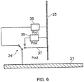
- FIG. 6 shows the grounding connection 25 and the groundplane 21 of the main PCB substrate 20.
- the grounding connection 25 connects to the groundplane 21 by way of a switch 34 that can switch in different inductive and/or capacitive components 35 or 36, or provide a direct connection 37.
- the complex grounding loads were chosen so that in switch position 1 the low band of the antenna covered the LTE band 700-760 MHz; in switch position 2, 750-800 MHz and in switch position 3, the GSM band 824-960 MHz.
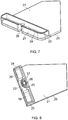
- Figure 8 shows a variation of the embodiment of Figure 2 , where parts of the substrate 23 are cut out from the second surface on either side of the central complex load 27.
- the cut-outs are generally cuboidal in shape, although other shapes and volumes may be useful. The efficiency benefits are mainly in the high frequency band.
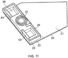
- Figures 9 and 10 show a variation in which the main loop antenna is defined by the track 24 and complex load 27 on the substrate 23 is arranged so as to leave a central area 42 free for a cut-out 40 right through part of the antenna substrate 23.
- the objective here is not so much to reduce losses but rather to create a volume where a micro-USB connector 41 or similar may be located. It is often desirable to locate the antenna in the same place as connectors, for example at the bottom of a mobile phone handset.
- short capacitive or inductive stubs 43 may be attached to a driven or parasitic loop antenna 24 to improve the bandwidth, impedance match and/or efficiency, as shown in Figure 11 . It has been found particularly advantageous to use several such stubs 43, as part of the central complex load 27. The stubs 43 may also be used advantageously when connected to other parts of the loop structure 24. Cut-outs 39 in the substrate 23 may also be provided to improve efficiency.
- Figure 12 shows an example corresponding generally to that of Figures 9 and 10 in combination with an electrically small FM radio antenna 44 tuned to band 88-108 MHz and mounted on the reverse side of the main PCB 20 to the side on which the loop antenna 24 is mounted.
- one antenna is on the top surface of the PCB 20 and the other is directly below it on the undersurface of the main PCB 20. It is usually a problem to use two antennas so closely spaced because of the coupling between them but it has been found that the loop design of examples and the nature of the FM antenna (itself a type of loop) is such that very good isolation may exist between them.
- Figure 13 shows that the coupling between the two antennas 24 and 44 (the lower plot) is lower than -30 dB across the whole of the cellular band.
Claims (19)
- Multiband-Rahmenantenne (22), umfassend ein dielektrisches Substrat (23) mit gegenüberliegenden erster und zweiter Oberfläche und einer Leiterbahn (24), die auf dem Substrat (23) ausgebildet ist, wobei die Leiterbahn (24) eine Gesamtlänge von etwa einer halben Wellenlänge bei einer niedrigsten Betriebsfrequenz besitzt, wobei auf der ersten Oberfläche des Substrats (23) ein Einspeisepunkt und ein Erdungspunkt bereitgestellt sind, die zueinander benachbart sind, wobei sich die Leiterbahn (24) jeweils in im Wesentlichen entgegengesetzte Richtungen von dem Einspeisepunkt und Erdungspunkt erstreckt, dann zu einer Kante des dielektrischen Substrats (23) hin erstreckt, dann zur zweiten Oberfläche des dielektrischen Substrats (23) verläuft und dann über die zweite Oberfläche des dielektrischen Substrats (23) entlang eines Pfades verläuft, der im Wesentlichen dem auf der ersten Oberfläche des dielektrischen Substrats (23) genommenen Pfad folgt, bevor sie an jeweilige Seiten einer auf der zweiten Oberfläche des dielektrischen Substrats (23) ausgebildeten komplexen Reihenlast anschließt, die sich in einen zentralen Teil eines von der Leiterbahn (24) auf der zweiten Oberfläche des dielektrischen Substrats (23) gebildeten Rahmen hinein erstreckt, wobei die komplexe Reihenlast die Anpassung der Antenne verbessert, dadurch gekennzeichnet, dass die komplexe Reihenlast sowohl induktive als auch kapazitive Elemente umfasst, die als Bahnen auf der zweiten Oberfläche des dielektrischen Substrats (23) ausgebildet sind, um mindestens einen Spalt zwischen den Bahnen zu definieren, indem eine der Bahnen im Wesentlichen parallel zu einer anderen der Bahnen geführt wird, aber die andere Bahn galvanisch nicht kontaktiert.
- Antenne (22) nach Anspruch 1, wobei die Leiterbahn (24) so angeordnet ist, dass zwei Arme, einer auf jeder Seite der komplexen Reihenlast, definiert werden.
- Antenne (22) nach Anspruch 2, wobei die Arme symmetrisch angeordnet sind.
- Antenne (22) nach Anspruch 2, wobei die Arme nicht symmetrisch angeordnet sind; wobei gegebenenfalls ein Arm länger ist als der andere.
- Antenne (22) nach einem der vorstehenden Ansprüche, wobei die Leiterbahn (24) auf der ersten Oberfläche des dielektrischen Substrats (23) mittels Durchkontaktierungen oder Löcher durch das dielektrische Substrat (23) zur zweiten Oberfläche verläuft.
- Antenne (22) nach einem der vorstehenden Ansprüche, wobei die Leiterbahn (24) über die Kante des dielektrischen Substrats (23) von einer Oberfläche zur anderen verläuft.
- Antenne (22) nach einem der vorstehenden Ansprüche, wobei die Leiterbahn, ungeachtet der komplexen Reihenlast, im Wesentlichen symmetrisch ist über eine Spiegelebene, die zwischen der ersten und zweiten Oberfläche des Substrats definiert ist.
- Antenne (22) nach einem der Ansprüche 1 bis 6, wobei die Leiterbahn (24), ungeachtet der komplexen Reihenlast, nicht über eine Spiegelebene symmetrisch ist, die zwischen der ersten und zweiten Oberfläche des Substrats (23) definiert ist.
- Antenne (22) nach einem der vorstehenden Ansprüche, wobei die Leiterbahn (24) mit Armen oder Ausläufern oder sonstigen Verlängerungen versehen ist, die sich in den zentralen Teil des Rahmens hinein oder von diesem weg erstrecken.
- Antenne (22) nach einem der vorstehenden Ansprüche, die des Weiteren mit mindestens einem parasitären Strahlungselement versehen ist.
- Antenne (22) nach Anspruch 10, wobei das parasitäre Strahlungselement geerdet (an eine Massefläche angeschlossen) ist.
- Antenne (22) nach Anspruch 10, wobei das parasitäre Strahlungselement ungeerdet ist.
- Antenne (22) nach einem der vorstehenden Ansprüche, die auf einem Bereich einer Hauptplatine angebracht ist, der keine Massefläche aufweist.
- Antenne (22) nach einem der vorstehenden Ansprüche, wobei die Rahmenantenne durch eine komplexe Last geerdet ist, ausgewählt aus der Liste, die Folgendes umfasst: mindestens einen Induktor, mindestens einen Kondensator; mindestens eine Länge einer Übertragungsleitung; und jede Kombination davon in Reihe oder parallel, wobei gegebenenfalls der Erdungspunkt der Rahmenantenne zwischen verschiedenen komplexen Lasten schaltbar ist, um es der Antenne zu ermöglichen, verschiedene Frequenzbänder abzudecken.
- Antenne (22) nach einem der vorstehenden Ansprüche, wobei eine zentrale Aussparung in dem dielektrischen Substrat (23) ausgebildet ist.
- Antenne (22) nach einem der vorstehenden Ansprüche, wobei in der zweiten Oberfläche des dielektrischen Substrats (23) auf beiden Seiten einer Mittellinie darauf ein Ausschnitt ausgebildet ist.
- Antenne (22) nach einem der vorstehenden Ansprüche, wobei ein Ausschnitt durch das dielektrische Substrat (23) ausgebildet ist, um ein Volumen zu schaffen, in dem ein Verbinder angeordnet werden kann.
- Antenne (22) nach einem der vorstehenden Ansprüche, die des Weiteren mindestens eine kapazitive oder induktive Stichleitung umfasst, die auf dem dielektrischen Substrat (23) angebracht ist.
- Antenne (22) nach einem der vorstehenden Ansprüche, die auf einer Seite eines dielektrischen Hauptsubstrats (23) angebracht ist, in Kombination mit einer zweiten Antenne, die gegenüberliegend auf der anderen Seite des dielektrischen Hauptsubstrats (23) angebracht ist; wobei es sich bei der zweiten Antenne gegebenenfalls um eine FM-Funkantenne handelt.
Priority Applications (1)
| Application Number | Priority Date | Filing Date | Title |
|---|---|---|---|
| EP16189540.4A EP3148000B1 (de) | 2010-10-15 | 2011-09-28 | Rahmenantenne für ein mobiltelefon und andere anwendungen |
Applications Claiming Priority (2)
| Application Number | Priority Date | Filing Date | Title |
|---|---|---|---|
| GB1017472.0A GB2484540B (en) | 2010-10-15 | 2010-10-15 | A loop antenna for mobile handset and other applications |
| PCT/GB2011/051837 WO2012049473A2 (en) | 2010-10-15 | 2011-09-28 | A loop antenna for mobile handset and other applications |
Related Child Applications (2)
| Application Number | Title | Priority Date | Filing Date |
|---|---|---|---|
| EP16189540.4A Division EP3148000B1 (de) | 2010-10-15 | 2011-09-28 | Rahmenantenne für ein mobiltelefon und andere anwendungen |
| EP16189540.4A Division-Into EP3148000B1 (de) | 2010-10-15 | 2011-09-28 | Rahmenantenne für ein mobiltelefon und andere anwendungen |
Publications (2)
| Publication Number | Publication Date |
|---|---|
| EP2628209A2 EP2628209A2 (de) | 2013-08-21 |
| EP2628209B1 true EP2628209B1 (de) | 2017-06-07 |
Family
ID=43333909
Family Applications (2)
| Application Number | Title | Priority Date | Filing Date |
|---|---|---|---|
| EP16189540.4A Active EP3148000B1 (de) | 2010-10-15 | 2011-09-28 | Rahmenantenne für ein mobiltelefon und andere anwendungen |
| EP11764605.9A Active EP2628209B1 (de) | 2010-10-15 | 2011-09-28 | Eine rahmenantenne für mobilteile und andere anwendungen |
Family Applications Before (1)
| Application Number | Title | Priority Date | Filing Date |
|---|---|---|---|
| EP16189540.4A Active EP3148000B1 (de) | 2010-10-15 | 2011-09-28 | Rahmenantenne für ein mobiltelefon und andere anwendungen |
Country Status (13)
| Country | Link |
|---|---|
| US (3) | US9502771B2 (de) |
| EP (2) | EP3148000B1 (de) |
| JP (1) | JP6009448B2 (de) |
| KR (1) | KR101837225B1 (de) |
| CN (1) | CN103155281B (de) |
| BR (1) | BR112013008761A2 (de) |
| CA (1) | CA2813829C (de) |
| GB (2) | GB2484540B (de) |
| IN (1) | IN2013MN00694A (de) |
| RU (1) | RU2586272C2 (de) |
| SG (1) | SG189210A1 (de) |
| TW (2) | TWI549373B (de) |
| WO (1) | WO2012049473A2 (de) |
Families Citing this family (43)
| Publication number | Priority date | Publication date | Assignee | Title |
|---|---|---|---|---|
| GB2484540B (en) | 2010-10-15 | 2014-01-29 | Microsoft Corp | A loop antenna for mobile handset and other applications |
| GB2484542B (en) | 2010-10-15 | 2015-04-29 | Microsoft Technology Licensing Llc | LTE antenna pair for mimo/diversity operation in the LTE/GSM bands |
| US10116062B2 (en) * | 2012-05-07 | 2018-10-30 | Sony Mobile Communications Inc. | Looped multi-branch planar antennas having a floating parasitic element and wireless communications devices incorporating the same |
| EP2942835B1 (de) * | 2012-06-28 | 2018-08-22 | Murata Manufacturing Co., Ltd. | Antennenvorrichtung und kommunikationsendgerät |
| TWI495192B (zh) * | 2012-07-27 | 2015-08-01 | Askey Computer Corp | 多頻天線 |
| TWI513105B (zh) | 2012-08-30 | 2015-12-11 | Ind Tech Res Inst | 雙頻耦合饋入天線、交叉極化天線以及使用該天線的可調式波束模組 |
| US8922443B2 (en) | 2012-09-27 | 2014-12-30 | Apple Inc. | Distributed loop antenna with multiple subloops |
| US9425496B2 (en) | 2012-09-27 | 2016-08-23 | Apple Inc. | Distributed loop speaker enclosure antenna |
| JP5839236B2 (ja) * | 2012-10-16 | 2016-01-06 | カシオ計算機株式会社 | 携帯端末 |
| DE102012221940B4 (de) * | 2012-11-30 | 2022-05-12 | Robert Bosch Gmbh | Modul zur drahtlosen Kommunikation und Verfahren zum Herstellen eines Moduls zur drahtlosen Kommunikation |
| TWI619304B (zh) * | 2013-05-17 | 2018-03-21 | 群邁通訊股份有限公司 | 寬頻天線及應用該寬頻天線的無線通訊裝置 |
| WO2014188747A1 (ja) * | 2013-05-20 | 2014-11-27 | 株式会社村田製作所 | アンテナおよび無線通信装置 |
| CN104253300A (zh) * | 2013-06-26 | 2014-12-31 | 重庆美桀电子科技有限公司 | 一种可收发WiFi和GPS信号的双频段天线 |
| US9350077B1 (en) * | 2013-08-08 | 2016-05-24 | Amazon Technologies, Inc. | Low SAR folded loop-shaped antenna |
| JP6131816B2 (ja) | 2013-10-07 | 2017-05-24 | 株式会社デンソー | 変形折り返しダイポールアンテナ |
| CN104577304B (zh) * | 2013-10-18 | 2019-07-23 | 深圳富泰宏精密工业有限公司 | 天线结构及具有该天线结构的无线通信装置 |
| JP6414910B2 (ja) * | 2013-12-31 | 2018-10-31 | 華為終端(東莞)有限公司 | ループ状アンテナおよびモバイル端末 |
| CN104752819B (zh) * | 2013-12-31 | 2019-11-01 | 深圳富泰宏精密工业有限公司 | 天线结构及具有该天线结构的无线通信装置 |
| US20150303551A1 (en) * | 2014-04-16 | 2015-10-22 | King Slide Technology Co.,Ltd. | Communication device antenna |
| US9184494B1 (en) * | 2014-05-09 | 2015-11-10 | Futurewei Technologies, Inc. | Switchable Pi shape antenna |
| KR20160067541A (ko) * | 2014-12-04 | 2016-06-14 | 엘지전자 주식회사 | 안테나 모듈 및 이를 이용한 이동 단말기 |
| DE212016000166U1 (de) * | 2015-06-30 | 2018-03-13 | Murata Manufacturing Co., Ltd. | Kopplungsunterstützungsgerät und RFID-Kommunikationssystem |
| KR20170055351A (ko) * | 2015-11-11 | 2017-05-19 | 삼성전자주식회사 | 안테나 장치 및 그를 포함하는 전자 장치 |
| GB2545918B (en) * | 2015-12-30 | 2020-01-22 | Antenova Ltd | Reconfigurable antenna |
| CN205376750U (zh) * | 2016-01-12 | 2016-07-06 | 中磊电子(苏州)有限公司 | 双频天线 |
| KR20170103315A (ko) | 2016-03-03 | 2017-09-13 | 엘지전자 주식회사 | 이동 단말기 |
| US20170374684A1 (en) * | 2016-06-24 | 2017-12-28 | Chittabrata Ghosh | Identifier assignment for unassociated stations |
| CN107645038B (zh) * | 2016-07-20 | 2019-11-29 | 华为技术有限公司 | 一种天线及移动终端 |
| US10103435B2 (en) * | 2016-11-09 | 2018-10-16 | Dell Products L.P. | Systems and methods for transloop impedance matching of an antenna |
| US10320078B2 (en) | 2016-11-18 | 2019-06-11 | QuantalRF AG | Small form factor CPL antenna with balanced fed dipole electric field radiator |
| CN108288750B (zh) * | 2017-01-10 | 2021-10-22 | 摩托罗拉移动有限责任公司 | 具有至少部分横跨在臂的开口端之间的间隙的馈线导体的天线系统 |
| US10165574B2 (en) * | 2017-01-31 | 2018-12-25 | Qualcomm Incorporated | Vehicle-to-everything control channel design |
| JP6809609B2 (ja) * | 2017-06-27 | 2021-01-06 | 株式会社村田製作所 | デュアルバンド対応アンテナ装置 |
| EP3422473B1 (de) | 2017-06-30 | 2021-07-28 | GN Audio A/S | Antennenstruktur für ein headset |
| KR102469571B1 (ko) | 2018-01-25 | 2022-11-22 | 삼성전자주식회사 | 루프 타입 안테나 및 그것을 포함하는 전자 장치 |
| ES2737879A1 (es) * | 2018-07-16 | 2020-01-16 | Verisure Sarl | Placa de circuito impreso para la unidad de control de un sistema de alarma |
| KR102251239B1 (ko) * | 2019-09-20 | 2021-05-13 | (주)파트론 | 안테나 구조체 |
| KR102241220B1 (ko) * | 2019-09-20 | 2021-04-19 | (주)파트론 | 안테나 구조체 |
| TWI700862B (zh) * | 2019-10-23 | 2020-08-01 | 華碩電腦股份有限公司 | 迴圈式雙天線系統 |
| CN112751159B (zh) * | 2019-10-31 | 2022-06-10 | 华为终端有限公司 | 电子设备 |
| CN110970706B (zh) * | 2019-11-20 | 2021-04-09 | 珠海格力电器股份有限公司 | 多模天线、终端、多模天线的通信方法及装置及处理器 |
| CN111276810A (zh) * | 2020-02-18 | 2020-06-12 | 环鸿电子(昆山)有限公司 | 芯片天线 |
| TWI742987B (zh) * | 2021-01-13 | 2021-10-11 | 矽品精密工業股份有限公司 | 電子裝置及其電路板 |
Citations (1)
| Publication number | Priority date | Publication date | Assignee | Title |
|---|---|---|---|---|
| WO2006021914A1 (en) * | 2004-08-26 | 2006-03-02 | Koninklijke Philips Electronics N.V. | Rfid tag having a folded dipole |
Family Cites Families (64)
| Publication number | Priority date | Publication date | Assignee | Title |
|---|---|---|---|---|
| GB692692A (en) * | 1947-12-24 | 1953-06-10 | Charles Alexander Vivian Heath | Improvements in and relating to radio aerials |
| US3993998A (en) * | 1975-06-06 | 1976-11-23 | Kimmett James P | Directional loop antenna with plural dielectric coverings |
| JPS5434739A (en) * | 1977-08-24 | 1979-03-14 | Denki Kogyo Co Ltd | Method of matching antenna for multiple waves |
| US4940992A (en) * | 1988-04-11 | 1990-07-10 | Nguyen Tuan K | Balanced low profile hybrid antenna |
| JPH0518114U (ja) * | 1991-08-09 | 1993-03-05 | 東光株式会社 | マイクロストリツプアンテナ |
| EP0584882A1 (de) * | 1992-08-28 | 1994-03-02 | Philips Electronics Uk Limited | Rahmenantenne |
| US5554734A (en) | 1994-06-20 | 1996-09-10 | Ciba-Geigy Corporation | AZO dyes containing a bridge member based on stibene and morpholino-substituted triazine |
| JP3286543B2 (ja) * | 1996-11-22 | 2002-05-27 | 松下電器産業株式会社 | 無線機器用アンテナ装置 |
| JP3246365B2 (ja) * | 1996-12-06 | 2002-01-15 | 株式会社村田製作所 | 表面実装型アンテナ、アンテナ装置および通信機 |
| GB9806488D0 (en) * | 1998-03-27 | 1998-05-27 | Philips Electronics Nv | Radio apparatus |
| JPH11308033A (ja) * | 1998-04-20 | 1999-11-05 | Matsushita Electric Ind Co Ltd | ループアンテナ及びそのためのアンテナホルダー |
| JP3466941B2 (ja) * | 1998-12-24 | 2003-11-17 | 株式会社ユーシン | アンテナ装置 |
| JP3554960B2 (ja) * | 1999-06-25 | 2004-08-18 | 株式会社村田製作所 | アンテナ装置およびそれを用いた通信装置 |
| JP4221878B2 (ja) * | 2000-01-25 | 2009-02-12 | ソニー株式会社 | アンテナ装置 |
| JP4510244B2 (ja) * | 2000-07-19 | 2010-07-21 | パナソニック株式会社 | アンテナ装置 |
| JP2002252521A (ja) * | 2001-02-23 | 2002-09-06 | Aisin Seiki Co Ltd | ループアンテナ装置 |
| JP2003069330A (ja) * | 2001-06-15 | 2003-03-07 | Hitachi Metals Ltd | 表面実装型アンテナ及びそれを搭載した通信機器 |
| US6456243B1 (en) * | 2001-06-26 | 2002-09-24 | Ethertronics, Inc. | Multi frequency magnetic dipole antenna structures and methods of reusing the volume of an antenna |
| US6590542B1 (en) * | 2001-12-17 | 2003-07-08 | James B. Briggs | Double loop antenna |
| TW506163B (en) * | 2001-12-19 | 2002-10-11 | Ind Tech Res Inst | Planar inverted-F antenna |
| US7154449B2 (en) * | 2002-04-25 | 2006-12-26 | Cet Technologies Pte Ltd. | Antenna |
| DE60231127D1 (de) * | 2002-10-31 | 2009-03-26 | Sony Ericsson Mobile Comm Ab | Breitbandige Loop-Antenne |
| AU2003278100A1 (en) * | 2002-10-31 | 2004-05-25 | Sony Ericsson Mobile Communications Ab | Wideband loop antenna |
| AU2003303179A1 (en) * | 2002-12-17 | 2004-07-14 | Ethertronics, Inc. | Antennas with reduced space and improved performance |
| DE10347719B4 (de) * | 2003-06-25 | 2009-12-10 | Samsung Electro-Mechanics Co., Ltd., Suwon | Innere Antenne für ein mobiles Kommunikationsgerät |
| JP2005117099A (ja) | 2003-10-02 | 2005-04-28 | Murata Mfg Co Ltd | 携帯無線通信機 |
| JP4082341B2 (ja) * | 2003-12-02 | 2008-04-30 | トヨタ自動車株式会社 | アンテナ装置 |
| GB2409582B (en) * | 2003-12-24 | 2007-04-18 | Nokia Corp | Antenna for mobile communication terminals |
| JP3791923B2 (ja) * | 2004-01-13 | 2006-06-28 | 株式会社東芝 | 無線通信端末 |
| US7091911B2 (en) * | 2004-06-02 | 2006-08-15 | Research In Motion Limited | Mobile wireless communications device comprising non-planar internal antenna without ground plane overlap |
| JP5265915B2 (ja) | 2004-08-19 | 2013-08-14 | ザ・ホンコン・ポリテクニック・ユニバーシティ | プロテアソームを阻害するための(−)−エピガロカテキンガラート誘導体 |
| JP4372158B2 (ja) * | 2004-10-28 | 2009-11-25 | パナソニック株式会社 | 放送用受信機付き携帯電話 |
| KR100597581B1 (ko) * | 2004-11-05 | 2006-07-06 | 한국전자통신연구원 | 스터브를 포함한 대칭 구조의 다중대역 내장형 안테나 |
| JP4414940B2 (ja) * | 2005-06-14 | 2010-02-17 | ソニーケミカル&インフォメーションデバイス株式会社 | アンテナ装置及びアンテナ装置の調整方法 |
| US7489276B2 (en) * | 2005-06-27 | 2009-02-10 | Research In Motion Limited | Mobile wireless communications device comprising multi-frequency band antenna and related methods |
| WO2007020728A1 (ja) | 2005-08-12 | 2007-02-22 | Murata Manufacturing Co., Ltd. | アンテナ構造およびそれを備えた無線通信装置 |
| JP4311576B2 (ja) * | 2005-11-18 | 2009-08-12 | ソニー・エリクソン・モバイルコミュニケーションズ株式会社 | 折り返しダイポールアンテナ装置および携帯無線端末 |
| JP2007288561A (ja) * | 2006-04-18 | 2007-11-01 | Matsushita Electric Ind Co Ltd | 携帯無線機用アンテナ |
| US7589675B2 (en) * | 2006-05-19 | 2009-09-15 | Industrial Technology Research Institute | Broadband antenna |
| JP2007336331A (ja) * | 2006-06-16 | 2007-12-27 | Kuurii Components Kk | アンテナ装置 |
| JP2008042600A (ja) * | 2006-08-08 | 2008-02-21 | Kuurii Components Kk | アンテナ装置 |
| KR100824382B1 (ko) * | 2006-09-12 | 2008-04-22 | 삼성전자주식회사 | 정합회로가 일체로 형성된 폴디드 다이폴 루프 안테나 |
| JPWO2008035526A1 (ja) * | 2006-09-20 | 2010-01-28 | 株式会社村田製作所 | アンテナ構造およびそれを用いた無線通信装置 |
| JP4793210B2 (ja) * | 2006-10-02 | 2011-10-12 | 株式会社豊田中央研究所 | フォールデッドダイポールアンテナ |
| US7639194B2 (en) | 2006-11-30 | 2009-12-29 | Auden Techno Corp. | Dual-band loop antenna |
| US7423598B2 (en) * | 2006-12-06 | 2008-09-09 | Motorola, Inc. | Communication device with a wideband antenna |
| JP4378378B2 (ja) * | 2006-12-12 | 2009-12-02 | アルプス電気株式会社 | アンテナ装置 |
| US7265720B1 (en) * | 2006-12-29 | 2007-09-04 | Motorola, Inc. | Planar inverted-F antenna with parasitic conductor loop and device using same |
| US7595759B2 (en) * | 2007-01-04 | 2009-09-29 | Apple Inc. | Handheld electronic devices with isolated antennas |
| JP4311450B2 (ja) | 2007-01-12 | 2009-08-12 | 三菱電機株式会社 | アンテナ装置 |
| JP5018114B2 (ja) | 2007-02-07 | 2012-09-05 | 日本精工株式会社 | センサ付き軸受 |
| JP2008205680A (ja) * | 2007-02-19 | 2008-09-04 | Matsushita Electric Ind Co Ltd | アンテナ装置とこれを用いた電子機器 |
| US8446706B1 (en) * | 2007-10-10 | 2013-05-21 | Kovio, Inc. | High precision capacitors |
| EP2065795A1 (de) | 2007-11-30 | 2009-06-03 | Koninklijke KPN N.V. | Autozoom-Anzeigesystem und -verfahren |
| TWI411158B (zh) * | 2008-04-09 | 2013-10-01 | Acer Inc | 一種多頻折疊環形天線 |
| TWI360916B (en) * | 2008-06-06 | 2012-03-21 | Univ Nat Sun Yat Sen | A compact multiband loop antenna |
| US7911405B2 (en) * | 2008-08-05 | 2011-03-22 | Motorola, Inc. | Multi-band low profile antenna with low band differential mode |
| GB2472779B (en) * | 2009-08-17 | 2013-08-14 | Microsoft Corp | Antennas with multiple feed circuits |
| GB2484540B (en) | 2010-10-15 | 2014-01-29 | Microsoft Corp | A loop antenna for mobile handset and other applications |
| TWI442632B (zh) | 2011-04-14 | 2014-06-21 | Acer Inc | 行動通訊裝置及其天線結構 |
| CN102856631B (zh) | 2011-06-28 | 2015-04-22 | 财团法人工业技术研究院 | 天线与其通信装置 |
| US8654022B2 (en) | 2011-09-02 | 2014-02-18 | Dockon Ag | Multi-layered multi-band antenna |
| US9276317B1 (en) | 2012-03-02 | 2016-03-01 | Amazon Technologies, Inc. | Quad-mode antenna |
| TWI523332B (zh) | 2013-05-15 | 2016-02-21 | 宏碁股份有限公司 | 通訊裝置 |
-
2010
- 2010-10-15 GB GB1017472.0A patent/GB2484540B/en active Active
- 2010-10-15 GB GB1309731.6A patent/GB2500136B/en active Active
-
2011
- 2011-09-28 EP EP16189540.4A patent/EP3148000B1/de active Active
- 2011-09-28 US US13/878,971 patent/US9502771B2/en active Active
- 2011-09-28 CN CN201180049862.8A patent/CN103155281B/zh active Active
- 2011-09-28 WO PCT/GB2011/051837 patent/WO2012049473A2/en active Application Filing
- 2011-09-28 KR KR1020137010843A patent/KR101837225B1/ko active IP Right Grant
- 2011-09-28 RU RU2013120482/28A patent/RU2586272C2/ru not_active IP Right Cessation
- 2011-09-28 IN IN694MUN2013 patent/IN2013MN00694A/en unknown
- 2011-09-28 JP JP2013533279A patent/JP6009448B2/ja active Active
- 2011-09-28 BR BR112013008761A patent/BR112013008761A2/pt not_active IP Right Cessation
- 2011-09-28 SG SG2013024294A patent/SG189210A1/en unknown
- 2011-09-28 CA CA2813829A patent/CA2813829C/en active Active
- 2011-09-28 EP EP11764605.9A patent/EP2628209B1/de active Active
- 2011-10-13 TW TW100137082A patent/TWI549373B/zh active
- 2011-10-13 TW TW105116685A patent/TWI610491B/zh not_active IP Right Cessation
-
2015
- 2015-07-01 US US14/789,817 patent/US9543650B2/en active Active
-
2016
- 2016-09-30 US US15/282,100 patent/US9948003B2/en active Active
Patent Citations (1)
| Publication number | Priority date | Publication date | Assignee | Title |
|---|---|---|---|---|
| WO2006021914A1 (en) * | 2004-08-26 | 2006-03-02 | Koninklijke Philips Electronics N.V. | Rfid tag having a folded dipole |
Also Published As
Similar Documents
| Publication | Publication Date | Title |
|---|---|---|
| US9948003B2 (en) | Loop antenna for mobile handset and other applications | |
| EP1869726B1 (de) | Antenne mit mehreren resonanzfrequenzen | |
| KR100993439B1 (ko) | 안테나 장치 및 무선 통신 장치 | |
| US8094080B2 (en) | Antenna and radio communication apparatus | |
| US6747601B2 (en) | Antenna arrangement | |
| JP4858860B2 (ja) | マルチバンドアンテナ | |
| KR100623079B1 (ko) | 적층 구조 다중 대역 안테나 | |
| EP2907195A1 (de) | Mehrbandantenne | |
| JP2005510927A (ja) | デュアルバンドアンテナ装置 | |
| KR20110122849A (ko) | 안테나 장치, 인쇄 회로 보드, 휴대용 전자 장치 및 변환 키트 | |
| CN110770975B (zh) | 天线装置和包括此类天线装置的设备 | |
| JP2005020266A (ja) | 多周波アンテナ装置 | |
| JPH09232854A (ja) | 移動無線機用小型平面アンテナ装置 |
Legal Events
| Date | Code | Title | Description |
|---|---|---|---|
| PUAI | Public reference made under article 153(3) epc to a published international application that has entered the european phase |
Free format text: ORIGINAL CODE: 0009012 |
|
| 17P | Request for examination filed |
Effective date: 20130424 |
|
| AK | Designated contracting states |
Kind code of ref document: A2 Designated state(s): AL AT BE BG CH CY CZ DE DK EE ES FI FR GB GR HR HU IE IS IT LI LT LU LV MC MK MT NL NO PL PT RO RS SE SI SK SM TR |
|
| DAX | Request for extension of the european patent (deleted) | ||
| RAP1 | Party data changed (applicant data changed or rights of an application transferred) |
Owner name: MICROSOFT TECHNOLOGY LICENSING, LLC |
|
| 17Q | First examination report despatched |
Effective date: 20160524 |
|
| REG | Reference to a national code |
Ref country code: DE Ref legal event code: R079 Ref document number: 602011038539 Country of ref document: DE Free format text: PREVIOUS MAIN CLASS: H01Q0001380000 Ipc: H01Q0001240000 |
|
| GRAP | Despatch of communication of intention to grant a patent |
Free format text: ORIGINAL CODE: EPIDOSNIGR1 |
|
| STAA | Information on the status of an ep patent application or granted ep patent |
Free format text: STATUS: GRANT OF PATENT IS INTENDED |
|
| RIC1 | Information provided on ipc code assigned before grant |
Ipc: H01Q 1/38 20060101ALI20161213BHEP Ipc: H01Q 5/364 20150101ALI20161213BHEP Ipc: H01Q 5/321 20150101ALI20161213BHEP Ipc: H01Q 5/392 20150101ALI20161213BHEP Ipc: H01Q 5/378 20150101ALI20161213BHEP Ipc: H01Q 7/00 20060101ALI20161213BHEP Ipc: H01Q 9/26 20060101ALI20161213BHEP Ipc: H01Q 1/24 20060101AFI20161213BHEP |
|
| INTG | Intention to grant announced |
Effective date: 20170103 |
|
| GRAS | Grant fee paid |
Free format text: ORIGINAL CODE: EPIDOSNIGR3 |
|
| GRAA | (expected) grant |
Free format text: ORIGINAL CODE: 0009210 |
|
| STAA | Information on the status of an ep patent application or granted ep patent |
Free format text: STATUS: THE PATENT HAS BEEN GRANTED |
|
| AK | Designated contracting states |
Kind code of ref document: B1 Designated state(s): AL AT BE BG CH CY CZ DE DK EE ES FI FR GB GR HR HU IE IS IT LI LT LU LV MC MK MT NL NO PL PT RO RS SE SI SK SM TR |
|
| REG | Reference to a national code |
Ref country code: GB Ref legal event code: FG4D |
|
| GRAA | (expected) grant |
Free format text: ORIGINAL CODE: 0009210 |
|
| REG | Reference to a national code |
Ref country code: CH Ref legal event code: EP Ref country code: AT Ref legal event code: REF Ref document number: 899847 Country of ref document: AT Kind code of ref document: T Effective date: 20170615 |
|
| REG | Reference to a national code |
Ref country code: IE Ref legal event code: FG4D |
|
| REG | Reference to a national code |
Ref country code: DE Ref legal event code: R096 Ref document number: 602011038539 Country of ref document: DE |
|
| REG | Reference to a national code |
Ref country code: FR Ref legal event code: PLFP Year of fee payment: 7 |
|
| REG | Reference to a national code |
Ref country code: NL Ref legal event code: FP |
|
| REG | Reference to a national code |
Ref country code: LT Ref legal event code: MG4D |
|
| PG25 | Lapsed in a contracting state [announced via postgrant information from national office to epo] |
Ref country code: FI Free format text: LAPSE BECAUSE OF FAILURE TO SUBMIT A TRANSLATION OF THE DESCRIPTION OR TO PAY THE FEE WITHIN THE PRESCRIBED TIME-LIMIT Effective date: 20170607 Ref country code: LT Free format text: LAPSE BECAUSE OF FAILURE TO SUBMIT A TRANSLATION OF THE DESCRIPTION OR TO PAY THE FEE WITHIN THE PRESCRIBED TIME-LIMIT Effective date: 20170607 Ref country code: HR Free format text: LAPSE BECAUSE OF FAILURE TO SUBMIT A TRANSLATION OF THE DESCRIPTION OR TO PAY THE FEE WITHIN THE PRESCRIBED TIME-LIMIT Effective date: 20170607 Ref country code: GR Free format text: LAPSE BECAUSE OF FAILURE TO SUBMIT A TRANSLATION OF THE DESCRIPTION OR TO PAY THE FEE WITHIN THE PRESCRIBED TIME-LIMIT Effective date: 20170908 Ref country code: NO Free format text: LAPSE BECAUSE OF FAILURE TO SUBMIT A TRANSLATION OF THE DESCRIPTION OR TO PAY THE FEE WITHIN THE PRESCRIBED TIME-LIMIT Effective date: 20170907 Ref country code: ES Free format text: LAPSE BECAUSE OF FAILURE TO SUBMIT A TRANSLATION OF THE DESCRIPTION OR TO PAY THE FEE WITHIN THE PRESCRIBED TIME-LIMIT Effective date: 20170607 |
|
| REG | Reference to a national code |
Ref country code: AT Ref legal event code: MK05 Ref document number: 899847 Country of ref document: AT Kind code of ref document: T Effective date: 20170607 |
|
| PG25 | Lapsed in a contracting state [announced via postgrant information from national office to epo] |
Ref country code: BG Free format text: LAPSE BECAUSE OF FAILURE TO SUBMIT A TRANSLATION OF THE DESCRIPTION OR TO PAY THE FEE WITHIN THE PRESCRIBED TIME-LIMIT Effective date: 20170907 Ref country code: RS Free format text: LAPSE BECAUSE OF FAILURE TO SUBMIT A TRANSLATION OF THE DESCRIPTION OR TO PAY THE FEE WITHIN THE PRESCRIBED TIME-LIMIT Effective date: 20170607 Ref country code: SE Free format text: LAPSE BECAUSE OF FAILURE TO SUBMIT A TRANSLATION OF THE DESCRIPTION OR TO PAY THE FEE WITHIN THE PRESCRIBED TIME-LIMIT Effective date: 20170607 Ref country code: LV Free format text: LAPSE BECAUSE OF FAILURE TO SUBMIT A TRANSLATION OF THE DESCRIPTION OR TO PAY THE FEE WITHIN THE PRESCRIBED TIME-LIMIT Effective date: 20170607 |
|
| PG25 | Lapsed in a contracting state [announced via postgrant information from national office to epo] |
Ref country code: AT Free format text: LAPSE BECAUSE OF FAILURE TO SUBMIT A TRANSLATION OF THE DESCRIPTION OR TO PAY THE FEE WITHIN THE PRESCRIBED TIME-LIMIT Effective date: 20170607 Ref country code: SK Free format text: LAPSE BECAUSE OF FAILURE TO SUBMIT A TRANSLATION OF THE DESCRIPTION OR TO PAY THE FEE WITHIN THE PRESCRIBED TIME-LIMIT Effective date: 20170607 Ref country code: RO Free format text: LAPSE BECAUSE OF FAILURE TO SUBMIT A TRANSLATION OF THE DESCRIPTION OR TO PAY THE FEE WITHIN THE PRESCRIBED TIME-LIMIT Effective date: 20170607 Ref country code: CZ Free format text: LAPSE BECAUSE OF FAILURE TO SUBMIT A TRANSLATION OF THE DESCRIPTION OR TO PAY THE FEE WITHIN THE PRESCRIBED TIME-LIMIT Effective date: 20170607 Ref country code: EE Free format text: LAPSE BECAUSE OF FAILURE TO SUBMIT A TRANSLATION OF THE DESCRIPTION OR TO PAY THE FEE WITHIN THE PRESCRIBED TIME-LIMIT Effective date: 20170607 |
|
| PG25 | Lapsed in a contracting state [announced via postgrant information from national office to epo] |
Ref country code: SM Free format text: LAPSE BECAUSE OF FAILURE TO SUBMIT A TRANSLATION OF THE DESCRIPTION OR TO PAY THE FEE WITHIN THE PRESCRIBED TIME-LIMIT Effective date: 20170607 Ref country code: IS Free format text: LAPSE BECAUSE OF FAILURE TO SUBMIT A TRANSLATION OF THE DESCRIPTION OR TO PAY THE FEE WITHIN THE PRESCRIBED TIME-LIMIT Effective date: 20171007 Ref country code: IT Free format text: LAPSE BECAUSE OF FAILURE TO SUBMIT A TRANSLATION OF THE DESCRIPTION OR TO PAY THE FEE WITHIN THE PRESCRIBED TIME-LIMIT Effective date: 20170607 Ref country code: PL Free format text: LAPSE BECAUSE OF FAILURE TO SUBMIT A TRANSLATION OF THE DESCRIPTION OR TO PAY THE FEE WITHIN THE PRESCRIBED TIME-LIMIT Effective date: 20170607 |
|
| REG | Reference to a national code |
Ref country code: DE Ref legal event code: R097 Ref document number: 602011038539 Country of ref document: DE |
|
| PLBE | No opposition filed within time limit |
Free format text: ORIGINAL CODE: 0009261 |
|
| STAA | Information on the status of an ep patent application or granted ep patent |
Free format text: STATUS: NO OPPOSITION FILED WITHIN TIME LIMIT |
|
| PG25 | Lapsed in a contracting state [announced via postgrant information from national office to epo] |
Ref country code: DK Free format text: LAPSE BECAUSE OF FAILURE TO SUBMIT A TRANSLATION OF THE DESCRIPTION OR TO PAY THE FEE WITHIN THE PRESCRIBED TIME-LIMIT Effective date: 20170607 |
|
| REG | Reference to a national code |
Ref country code: CH Ref legal event code: PL |
|
| 26N | No opposition filed |
Effective date: 20180308 |
|
| PG25 | Lapsed in a contracting state [announced via postgrant information from national office to epo] |
Ref country code: SI Free format text: LAPSE BECAUSE OF FAILURE TO SUBMIT A TRANSLATION OF THE DESCRIPTION OR TO PAY THE FEE WITHIN THE PRESCRIBED TIME-LIMIT Effective date: 20170607 Ref country code: MC Free format text: LAPSE BECAUSE OF FAILURE TO SUBMIT A TRANSLATION OF THE DESCRIPTION OR TO PAY THE FEE WITHIN THE PRESCRIBED TIME-LIMIT Effective date: 20170607 |
|
| REG | Reference to a national code |
Ref country code: IE Ref legal event code: MM4A |
|
| REG | Reference to a national code |
Ref country code: BE Ref legal event code: MM Effective date: 20170930 |
|
| PG25 | Lapsed in a contracting state [announced via postgrant information from national office to epo] |
Ref country code: LU Free format text: LAPSE BECAUSE OF NON-PAYMENT OF DUE FEES Effective date: 20170928 |
|
| PG25 | Lapsed in a contracting state [announced via postgrant information from national office to epo] |
Ref country code: CH Free format text: LAPSE BECAUSE OF NON-PAYMENT OF DUE FEES Effective date: 20170930 Ref country code: IE Free format text: LAPSE BECAUSE OF NON-PAYMENT OF DUE FEES Effective date: 20170928 Ref country code: LI Free format text: LAPSE BECAUSE OF NON-PAYMENT OF DUE FEES Effective date: 20170930 |
|
| REG | Reference to a national code |
Ref country code: FR Ref legal event code: PLFP Year of fee payment: 8 |
|
| PG25 | Lapsed in a contracting state [announced via postgrant information from national office to epo] |
Ref country code: BE Free format text: LAPSE BECAUSE OF NON-PAYMENT OF DUE FEES Effective date: 20170930 |
|
| PG25 | Lapsed in a contracting state [announced via postgrant information from national office to epo] |
Ref country code: MT Free format text: LAPSE BECAUSE OF NON-PAYMENT OF DUE FEES Effective date: 20170928 |
|
| PG25 | Lapsed in a contracting state [announced via postgrant information from national office to epo] |
Ref country code: HU Free format text: LAPSE BECAUSE OF FAILURE TO SUBMIT A TRANSLATION OF THE DESCRIPTION OR TO PAY THE FEE WITHIN THE PRESCRIBED TIME-LIMIT; INVALID AB INITIO Effective date: 20110928 |
|
| PG25 | Lapsed in a contracting state [announced via postgrant information from national office to epo] |
Ref country code: CY Free format text: LAPSE BECAUSE OF NON-PAYMENT OF DUE FEES Effective date: 20170607 |
|
| PG25 | Lapsed in a contracting state [announced via postgrant information from national office to epo] |
Ref country code: MK Free format text: LAPSE BECAUSE OF FAILURE TO SUBMIT A TRANSLATION OF THE DESCRIPTION OR TO PAY THE FEE WITHIN THE PRESCRIBED TIME-LIMIT Effective date: 20170607 |
|
| REG | Reference to a national code |
Ref country code: DE Ref legal event code: R082 Ref document number: 602011038539 Country of ref document: DE |
|
| PG25 | Lapsed in a contracting state [announced via postgrant information from national office to epo] |
Ref country code: TR Free format text: LAPSE BECAUSE OF FAILURE TO SUBMIT A TRANSLATION OF THE DESCRIPTION OR TO PAY THE FEE WITHIN THE PRESCRIBED TIME-LIMIT Effective date: 20170607 |
|
| PG25 | Lapsed in a contracting state [announced via postgrant information from national office to epo] |
Ref country code: PT Free format text: LAPSE BECAUSE OF FAILURE TO SUBMIT A TRANSLATION OF THE DESCRIPTION OR TO PAY THE FEE WITHIN THE PRESCRIBED TIME-LIMIT Effective date: 20170607 |
|
| PG25 | Lapsed in a contracting state [announced via postgrant information from national office to epo] |
Ref country code: AL Free format text: LAPSE BECAUSE OF FAILURE TO SUBMIT A TRANSLATION OF THE DESCRIPTION OR TO PAY THE FEE WITHIN THE PRESCRIBED TIME-LIMIT Effective date: 20170607 |
|
| P01 | Opt-out of the competence of the unified patent court (upc) registered |
Effective date: 20230501 |
|
| PGFP | Annual fee paid to national office [announced via postgrant information from national office to epo] |
Ref country code: NL Payment date: 20230822 Year of fee payment: 13 |
|
| PGFP | Annual fee paid to national office [announced via postgrant information from national office to epo] |
Ref country code: GB Payment date: 20230823 Year of fee payment: 13 |
|
| PGFP | Annual fee paid to national office [announced via postgrant information from national office to epo] |
Ref country code: FR Payment date: 20230822 Year of fee payment: 13 Ref country code: DE Payment date: 20230822 Year of fee payment: 13 |