EP2626230B1 - Dispositif d'alimentation électrique pour véhicule électrique - Google Patents
Dispositif d'alimentation électrique pour véhicule électrique Download PDFInfo
- Publication number
- EP2626230B1 EP2626230B1 EP13154354.8A EP13154354A EP2626230B1 EP 2626230 B1 EP2626230 B1 EP 2626230B1 EP 13154354 A EP13154354 A EP 13154354A EP 2626230 B1 EP2626230 B1 EP 2626230B1
- Authority
- EP
- European Patent Office
- Prior art keywords
- battery pack
- electric vehicle
- battery
- power supply
- vehicle
- Prior art date
- Legal status (The legal status is an assumption and is not a legal conclusion. Google has not performed a legal analysis and makes no representation as to the accuracy of the status listed.)
- Active
Links
- 230000002787 reinforcement Effects 0.000 claims description 3
- 239000012212 insulator Substances 0.000 description 43
- 239000006096 absorbing agent Substances 0.000 description 6
- 230000035939 shock Effects 0.000 description 6
- 238000003780 insertion Methods 0.000 description 3
- 230000037431 insertion Effects 0.000 description 3
- 239000000463 material Substances 0.000 description 2
- 239000011347 resin Substances 0.000 description 2
- 229920005989 resin Polymers 0.000 description 2
- 239000004576 sand Substances 0.000 description 2
- 239000004575 stone Substances 0.000 description 2
- 238000006243 chemical reaction Methods 0.000 description 1
- 230000008878 coupling Effects 0.000 description 1
- 238000010168 coupling process Methods 0.000 description 1
- 238000005859 coupling reaction Methods 0.000 description 1
- 230000007423 decrease Effects 0.000 description 1
- 230000003247 decreasing effect Effects 0.000 description 1
- 238000013461 design Methods 0.000 description 1
- 238000001514 detection method Methods 0.000 description 1
- 239000011499 joint compound Substances 0.000 description 1
- 239000003562 lightweight material Substances 0.000 description 1
- 238000004519 manufacturing process Methods 0.000 description 1
- 239000002184 metal Substances 0.000 description 1
- 238000000034 method Methods 0.000 description 1
- 238000012986 modification Methods 0.000 description 1
- 230000004048 modification Effects 0.000 description 1
- 238000012856 packing Methods 0.000 description 1
- 230000003014 reinforcing effect Effects 0.000 description 1
- XLYOFNOQVPJJNP-UHFFFAOYSA-N water Substances O XLYOFNOQVPJJNP-UHFFFAOYSA-N 0.000 description 1
Images


Classifications
-
- B—PERFORMING OPERATIONS; TRANSPORTING
- B60—VEHICLES IN GENERAL
- B60R—VEHICLES, VEHICLE FITTINGS, OR VEHICLE PARTS, NOT OTHERWISE PROVIDED FOR
- B60R16/00—Electric or fluid circuits specially adapted for vehicles and not otherwise provided for; Arrangement of elements of electric or fluid circuits specially adapted for vehicles and not otherwise provided for
- B60R16/02—Electric or fluid circuits specially adapted for vehicles and not otherwise provided for; Arrangement of elements of electric or fluid circuits specially adapted for vehicles and not otherwise provided for electric constitutive elements
- B60R16/03—Electric or fluid circuits specially adapted for vehicles and not otherwise provided for; Arrangement of elements of electric or fluid circuits specially adapted for vehicles and not otherwise provided for electric constitutive elements for supply of electrical power to vehicle subsystems or for
-
- B—PERFORMING OPERATIONS; TRANSPORTING
- B60—VEHICLES IN GENERAL
- B60L—PROPULSION OF ELECTRICALLY-PROPELLED VEHICLES; SUPPLYING ELECTRIC POWER FOR AUXILIARY EQUIPMENT OF ELECTRICALLY-PROPELLED VEHICLES; ELECTRODYNAMIC BRAKE SYSTEMS FOR VEHICLES IN GENERAL; MAGNETIC SUSPENSION OR LEVITATION FOR VEHICLES; MONITORING OPERATING VARIABLES OF ELECTRICALLY-PROPELLED VEHICLES; ELECTRIC SAFETY DEVICES FOR ELECTRICALLY-PROPELLED VEHICLES
- B60L50/00—Electric propulsion with power supplied within the vehicle
- B60L50/50—Electric propulsion with power supplied within the vehicle using propulsion power supplied by batteries or fuel cells
- B60L50/60—Electric propulsion with power supplied within the vehicle using propulsion power supplied by batteries or fuel cells using power supplied by batteries
- B60L50/64—Constructional details of batteries specially adapted for electric vehicles
-
- B—PERFORMING OPERATIONS; TRANSPORTING
- B60—VEHICLES IN GENERAL
- B60L—PROPULSION OF ELECTRICALLY-PROPELLED VEHICLES; SUPPLYING ELECTRIC POWER FOR AUXILIARY EQUIPMENT OF ELECTRICALLY-PROPELLED VEHICLES; ELECTRODYNAMIC BRAKE SYSTEMS FOR VEHICLES IN GENERAL; MAGNETIC SUSPENSION OR LEVITATION FOR VEHICLES; MONITORING OPERATING VARIABLES OF ELECTRICALLY-PROPELLED VEHICLES; ELECTRIC SAFETY DEVICES FOR ELECTRICALLY-PROPELLED VEHICLES
- B60L50/00—Electric propulsion with power supplied within the vehicle
- B60L50/50—Electric propulsion with power supplied within the vehicle using propulsion power supplied by batteries or fuel cells
- B60L50/60—Electric propulsion with power supplied within the vehicle using propulsion power supplied by batteries or fuel cells using power supplied by batteries
- B60L50/66—Arrangements of batteries
-
- B—PERFORMING OPERATIONS; TRANSPORTING
- B60—VEHICLES IN GENERAL
- B60L—PROPULSION OF ELECTRICALLY-PROPELLED VEHICLES; SUPPLYING ELECTRIC POWER FOR AUXILIARY EQUIPMENT OF ELECTRICALLY-PROPELLED VEHICLES; ELECTRODYNAMIC BRAKE SYSTEMS FOR VEHICLES IN GENERAL; MAGNETIC SUSPENSION OR LEVITATION FOR VEHICLES; MONITORING OPERATING VARIABLES OF ELECTRICALLY-PROPELLED VEHICLES; ELECTRIC SAFETY DEVICES FOR ELECTRICALLY-PROPELLED VEHICLES
- B60L53/00—Methods of charging batteries, specially adapted for electric vehicles; Charging stations or on-board charging equipment therefor; Exchange of energy storage elements in electric vehicles
- B60L53/80—Exchanging energy storage elements, e.g. removable batteries
-
- B—PERFORMING OPERATIONS; TRANSPORTING
- B62—LAND VEHICLES FOR TRAVELLING OTHERWISE THAN ON RAILS
- B62J—CYCLE SADDLES OR SEATS; AUXILIARY DEVICES OR ACCESSORIES SPECIALLY ADAPTED TO CYCLES AND NOT OTHERWISE PROVIDED FOR, e.g. ARTICLE CARRIERS OR CYCLE PROTECTORS
- B62J43/00—Arrangements of batteries
- B62J43/10—Arrangements of batteries for propulsion
- B62J43/16—Arrangements of batteries for propulsion on motorcycles or the like
-
- B—PERFORMING OPERATIONS; TRANSPORTING
- B62—LAND VEHICLES FOR TRAVELLING OTHERWISE THAN ON RAILS
- B62J—CYCLE SADDLES OR SEATS; AUXILIARY DEVICES OR ACCESSORIES SPECIALLY ADAPTED TO CYCLES AND NOT OTHERWISE PROVIDED FOR, e.g. ARTICLE CARRIERS OR CYCLE PROTECTORS
- B62J43/00—Arrangements of batteries
- B62J43/20—Arrangements of batteries characterised by the mounting
-
- B—PERFORMING OPERATIONS; TRANSPORTING
- B60—VEHICLES IN GENERAL
- B60L—PROPULSION OF ELECTRICALLY-PROPELLED VEHICLES; SUPPLYING ELECTRIC POWER FOR AUXILIARY EQUIPMENT OF ELECTRICALLY-PROPELLED VEHICLES; ELECTRODYNAMIC BRAKE SYSTEMS FOR VEHICLES IN GENERAL; MAGNETIC SUSPENSION OR LEVITATION FOR VEHICLES; MONITORING OPERATING VARIABLES OF ELECTRICALLY-PROPELLED VEHICLES; ELECTRIC SAFETY DEVICES FOR ELECTRICALLY-PROPELLED VEHICLES
- B60L2200/00—Type of vehicles
- B60L2200/12—Bikes
-
- B—PERFORMING OPERATIONS; TRANSPORTING
- B62—LAND VEHICLES FOR TRAVELLING OTHERWISE THAN ON RAILS
- B62K—CYCLES; CYCLE FRAMES; CYCLE STEERING DEVICES; RIDER-OPERATED TERMINAL CONTROLS SPECIALLY ADAPTED FOR CYCLES; CYCLE AXLE SUSPENSIONS; CYCLE SIDE-CARS, FORECARS, OR THE LIKE
- B62K2204/00—Adaptations for driving cycles by electric motor
-
- Y—GENERAL TAGGING OF NEW TECHNOLOGICAL DEVELOPMENTS; GENERAL TAGGING OF CROSS-SECTIONAL TECHNOLOGIES SPANNING OVER SEVERAL SECTIONS OF THE IPC; TECHNICAL SUBJECTS COVERED BY FORMER USPC CROSS-REFERENCE ART COLLECTIONS [XRACs] AND DIGESTS
- Y02—TECHNOLOGIES OR APPLICATIONS FOR MITIGATION OR ADAPTATION AGAINST CLIMATE CHANGE
- Y02T—CLIMATE CHANGE MITIGATION TECHNOLOGIES RELATED TO TRANSPORTATION
- Y02T10/00—Road transport of goods or passengers
- Y02T10/60—Other road transportation technologies with climate change mitigation effect
- Y02T10/70—Energy storage systems for electromobility, e.g. batteries
-
- Y—GENERAL TAGGING OF NEW TECHNOLOGICAL DEVELOPMENTS; GENERAL TAGGING OF CROSS-SECTIONAL TECHNOLOGIES SPANNING OVER SEVERAL SECTIONS OF THE IPC; TECHNICAL SUBJECTS COVERED BY FORMER USPC CROSS-REFERENCE ART COLLECTIONS [XRACs] AND DIGESTS
- Y02—TECHNOLOGIES OR APPLICATIONS FOR MITIGATION OR ADAPTATION AGAINST CLIMATE CHANGE
- Y02T—CLIMATE CHANGE MITIGATION TECHNOLOGIES RELATED TO TRANSPORTATION
- Y02T10/00—Road transport of goods or passengers
- Y02T10/60—Other road transportation technologies with climate change mitigation effect
- Y02T10/7072—Electromobility specific charging systems or methods for batteries, ultracapacitors, supercapacitors or double-layer capacitors
-
- Y—GENERAL TAGGING OF NEW TECHNOLOGICAL DEVELOPMENTS; GENERAL TAGGING OF CROSS-SECTIONAL TECHNOLOGIES SPANNING OVER SEVERAL SECTIONS OF THE IPC; TECHNICAL SUBJECTS COVERED BY FORMER USPC CROSS-REFERENCE ART COLLECTIONS [XRACs] AND DIGESTS
- Y02—TECHNOLOGIES OR APPLICATIONS FOR MITIGATION OR ADAPTATION AGAINST CLIMATE CHANGE
- Y02T—CLIMATE CHANGE MITIGATION TECHNOLOGIES RELATED TO TRANSPORTATION
- Y02T90/00—Enabling technologies or technologies with a potential or indirect contribution to GHG emissions mitigation
- Y02T90/10—Technologies relating to charging of electric vehicles
- Y02T90/12—Electric charging stations
-
- Y—GENERAL TAGGING OF NEW TECHNOLOGICAL DEVELOPMENTS; GENERAL TAGGING OF CROSS-SECTIONAL TECHNOLOGIES SPANNING OVER SEVERAL SECTIONS OF THE IPC; TECHNICAL SUBJECTS COVERED BY FORMER USPC CROSS-REFERENCE ART COLLECTIONS [XRACs] AND DIGESTS
- Y02—TECHNOLOGIES OR APPLICATIONS FOR MITIGATION OR ADAPTATION AGAINST CLIMATE CHANGE
- Y02T—CLIMATE CHANGE MITIGATION TECHNOLOGIES RELATED TO TRANSPORTATION
- Y02T90/00—Enabling technologies or technologies with a potential or indirect contribution to GHG emissions mitigation
- Y02T90/10—Technologies relating to charging of electric vehicles
- Y02T90/14—Plug-in electric vehicles
Definitions
- the present invention relates to a power supply device for an electric vehicle. More particularly, the invention relates to a power supply device for an electric vehicle which can allow an increased power supply capacity and an enhanced operability in mounting and detaching the power supply device to and from an electric vehicle, while providing a locking mechanism.
- Japanese Patent Laid-open No. 2003-231493 describes a motorcycle wherein a battery pack is mounted on a battery holder attached to a vehicle body. Specifically, this document shows a battery pack mounting structure and a lock mechanism wherein a groove part provided at an upper surface of the battery pack is provided with a hook part, and a mounting part fixed to a seat tube is provided with an engagement part for engagement with the hook part, the engagement part being movable inward and outward in the vertical direction.
- a handle for use in carrying the battery pack is provided at an upper portion of the battery pack so as to be located on the vehicle body rear side, or on the rear wheel side.
- the handle provided on the battery pack is disposed in a narrow place, between the mounting part projecting rearwardly from the seat tube and the rear wheel (which is located just to the rear of the battery pack). Therefore, there is little space around the handle. Accordingly, when mounting or detaching the battery pack, a user must put a hand into the narrow space between the mounting part and the rear wheel, which leads to poor operability.
- the hook part to be engaged with the mounting part is provided on the battery pack body side, in other words, on the side of the battery case in which the battery cells are accommodated. Therefore, the volume for accommodating the battery cells is reduced, and this can limit battery capacity.
- an electric vehicle with a power supply device which comprises a battery case for accommodating battery cells for supplying electric power to an electric motor of the electric vehicle and which can be mounted to and detached from the electric vehicle, wherein the battery case has a part extending to above a battery cell accommodating part; the extending part is provided with a handle including a grip part arranged so as to extend in the longitudinal direction of the vehicle when the power supply device is mounted on the electric vehicle; and an engagement part for engagement with a movable part of a lock device attached to the electric vehicle is formed at either the front or the back surface of the handle; characterized in that the electric vehicle includes: a main frame of a monocoque type which has an upwardly curved shape; a pivot by which a front end of a swing arm is supported on the main frame; the electric motor disposed forwardly of the pivot; and a power drive unit disposed forwardly of the electric motor, the power supply device being disposed between the electric motor and the power drive unit; wherein
- the electric motor is disposed at the front of the swing arm pivoting part of the monocoque-type main frame
- the power supply device is disposed at the front of the electric motor
- the power drive unit (PDU) is disposed at the front of the power supply device.
- the movable part of the lock device is a lock pin which can be advanced and retracted in the longitudinal direction of the electric vehicle relative to the lock device, and the engagement part is an engagement hole for accepting the lock pin.
- the handle extends above the battery case, and is provided with an engagement part (an engagement hole) for engagement with the movable part (the lock pin) of the lock device. Therefore, the power supply device can be engaged with the lock device on the vehicle body to achieve locking, without reducing the capacity of the battery cell accommodating part. Further, as the engagement hole for engagement with the lock pin is provided at a side surface of the handle so as not to interfere with the grip part, the battery pack is easy to handle.
- the power supply device comprises: a motor case in which the electric motor is accommodated and which is supported on the main frame; a terminal base incorporating a male-side terminal which can be coupled to a female-side terminal disposed at a lower portion of the battery case; a battery pack cover, provided with the terminal base at a lower portion thereof, and having a space such that the battery case can be disposed on the terminal base; and a battery pack support stay for connecting the battery cover to the motor case.
- the female-side terminals (which are located at a lower portion of the battery case) and the male-side terminals (which are provided on the terminal base at a lower portion inside the battery cover) can be coupled to each other, by accommodating the battery case in the battery pack cover.
- a lock device support stay is joined to the main frame and supports the lock device, and the lock device support stay has an extension part which extends so as to be coupled to an upper portion of the battery pack cover.
- the battery pack cover can be fixed not only at a lower portion thereof but also at an upper portion thereof, by coupling the battery pack cover to the main frame by means of the lock device support stay.
- the main frame of the electric vehicle has an under frame extended downward in front of the battery pack cover, and a skid plate is attached to the under frame.
- the battery pack and the motor case can be protected by the skid plate from small stones, sand, etc. flying toward them.
- a ring is fitted into an inner circumferential surface of the engagement hole and serves as a reinforcement member.
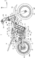
- Fig. 1 is a right side view of a part of an electric vehicle provided with a power supply device according to an embodiment of the present invention
- Fig. 2 is a left side view of the same
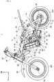
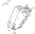
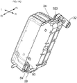
- Fig. 3 is a perspective view of a part of the electric vehicle as viewed from a right front side.
- the front of the electric vehicle 1 will be denoted by reference sign Fr, the rear by reference sign Rr, the left by reference sign L, the right by reference sign R, and the upper side by reference sign Up.
- the directions (sides) as used herein are with respect to the electric vehicle in use.
- the electric vehicle 1 is a motorcycle of an off-road type in which an electric motor is used as a drive source (hereafter, the "electric vehicle” is referred to as a "motorcycle”).
- the motorcycle 1 has a main frame 3 which is joined to a head pipe 2 at a front end thereof and which extends downwards and rearwards.
- the main frame 3 has a monocoque body composed of an upwardly curved single pipe.
- the main frame 3 can be formed of any suitable material, and may be integrally formed with the head pipe 2.
- Pivot plates 4 are joined to a lower rear portion of the main frame 3, and the pivot plates 4 are provided with a pivot 5 and a pivot 6 extending in the lateral (width) direction of the vehicle.
- the pivot 5 supports a pair of left and right swing arms 7 in a vertically swingable manner.
- the pivot 6, which is located below the pivot 5, supports a rear brake pedal 8, which is disposed on the right side of the electric motorcycle 1, in a vertically swingable manner.
- a side stand (not shown) can be pivotally supported on the left side of the electric motorcycle 1.
- a pair of left and right seat frames 9 and shock absorber front support brackets 10 are joined to a curved intermediate portion of the main frame 3.
- the shock absorber front support brackets 10 are reinforced with a stay 12.
- the seat frames 9 are joined to the main frame 3 at their front end portions, and extend toward the rear of the vehicle body.
- Sub frames 11 are provided, which are each joined to the main frame 3 and the seat frame 9 at front and rear ends thereof.
- the seat frames 9 are supported from below and reinforced by the sub frames 11.
- Rear wheel support plates 13 are joined respectively to rear portions of the left and right swing arms 7. Furthermore, rear end portions of left and right sub pipes 14 are joined to upper portions of the rear wheel support plates 13, and the left and right sub pipes extend toward the front side of the vehicle body. Between the sub pipe 14 and the swing arm 7, a connection tube 15 is provided which interconnects them.
- a shock absorber rear support bracket 16 is joined to an upper portion of the sub pipe 14.
- a rear shock absorber 17 is provided, and is pivotally supported by the shock absorber front support brackets 10 and the shock absorber rear cushion support brackets 16.
- a rider seat (not shown) is mounted on the seat frames 9 and the main frame 3.
- a driving device 18 is provided on the main frame 3, and a battery pack 19 provided on the main frame 3 and located forwardly of the driving device 18 serves as a power supply device.
- the battery pack 19 includes a plurality of battery cells (not shown) accommodated in a battery case 20.
- the driving device 18 includes an electric motor 21 and a reduction gear 22, and is covered with a driving device case (hereafter referred to as "motor case") 23.
- motor case 23 As the driving device 18 is covered with the motor case 23, it should be drawn in broken lines; however, for simplicity and to allow better understanding of its shape, the driving device 18 is shown in solid lines.
- the motor case 23 is connected to hanger brackets 24 and 25 and a pivot plate 4, whereby it is suspended at three positions.
- the battery pack 19 includes: a battery pack holding stay 27 connected to a lower portion of the motor case 23 and extending forward from the motor case 23; a battery pack cover 28 fixed to the battery pack holding stay 27; and a terminal base 29 fixed to a lower portion of the battery pack cover 28.
- a lock device support stay 30 and a PDU bracket 31, which protrude downward, are joined to front portions of the main frame 3.
- a lock device 32 is mounted to the lock device support stay 30, which is located immediately forwardly of the battery pack 19, and a PDU (power drive unit) 33 is mounted to the PDU bracket 31, which is located near the head pipe 2.
- the PDU 33 is supplied with electric power from the battery pack 19, and performs digital phase control for the electric motor 21 in accordance with battery information (remaining battery power and the like), detection signals from various switches and sensors and the like provided on the motorcycle 1, and so on.
- a handle 34 which can be used for carrying the battery pack 19 is provided at an upper portion located on the front right side of the battery case 20 of the battery pack 19.
- the handle 34 is formed with a lock pin engagement part for engagement with a lock pin which projects from the lock device 32; the lock pin and the lock pin engagement part will be described in detail later.
- a driving sprocket 36 is connected to an output shaft 35 of the reduction gear 22.
- a rear wheel WR (which is a driven wheel) is supported on the rear wheel support plates 13 through a rear axle 37, and a driven sprocket 38 is connected to the rear axle 37.
- a drive chain 39 is arranged between the driving sprocket 36 and the driven sprocket 38, and the power of the electric motor 21 (reduced in speed by the reduction gear 22) is transmitted to the rear axle 37 through the driven sprocket 38.
- the drive chain 39 is provided with a chain cover 61 (shown in Fig. 1 ), which covers an upper portion thereof.
- the rear axle 37 and the driven sprocket 38 are interconnected through a one-way clutch, so that the power of the electric motor 21 is only transmitted to the rear wheel WR in the direction for forward motion of the motorcycle 1.
- a step bar 42 extends in the lateral direction of the vehicle, and steps 40 and 41 on which the rider can put his or her feet are attached to the right and left ends of the step bar 42.
- the step bar 42 is attached to a bottom surface of the motor case 23 through a bracket 43.
- the rear brake pedal 8 which is supported on the pivot 6 includes a front arm part 801 operated by the rider's foot, and a rear arm part 802 which is connected through a brake cable 45 to an operation arm 44 of a rear brake (not shown) provided on the rear axle 37.
- a steering shaft (not shown) extends generally vertically through the head pipe 2 and is turnably supported.
- a pair of vertically extending front forks 51 are connected to a top bridge 49 and a bottom bridge 50 which are connected respectively to upper and lower portions of the steering shaft.
- a front axle 52 extending in the lateral direction of the vehicle is supported by the lower ends of the front forks 51, and a front wheel WF is rotatably supported on the front axle 52.
- a front fender 53 located above the front wheel WF is mounted to the front forks 51.
- a steering handlebar 48 is supported on the top bridge 49, and is provided with an accelerator grip 55.
- An accelerator cable 56 is connected to the accelerator grip 55.
- a turning amount of the accelerator grip 55 (accelerator position) is transmitted through the accelerator cable 56 to an accelerator position sensor (APS) 57 provided inside the motor case 23.
- APS accelerator position sensor
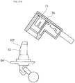
- Fig. 4 is a perspective view of the lock device 32 as viewed from a right upper rear side of the vehicle body
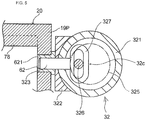
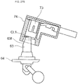
- Fig. 5 is a sectional view showing a section passing through the lock pin of the lock device 32, as viewed from the right side of the vehicle body.
- the lock device 32 includes a cylinder part 321 having a hollow cylindrical shape, a lock pin guide 322 projecting rearwardly from one side of the cylinder part 321, and a movable lock pin 323 extending orthogonally to the cylinder part 321 and passing through the lock pin guide 322.
- the cylinder part 321 is formed at its right end portion with a key hole 324, and a key (not shown) can be inserted in the key hole 324.
- a configuration is adopted wherein when the key is turned in a direction to turn the power supply on (for example, clockwise), the lock pin 323 is moved to project from the cylinder part 321, and when the key is turned in a direction to turn the power supply off, the lock pin 323 is retracted towards the cylinder part 321.
- a mechanism for conversion of the rotating motion of the key into longitudinal (forward and rearward) motion of the lock pin 323 includes an inner tube disk 325 provided coaxially with the cylinder part 321, as shown in Fig. 5 .
- an eccentric shaft 326 provided on the inner tube disk 325 is engaged with an end portion (an annular portion protruding into the inside of the cylinder) 327 of the lock pin 323, so that the lock pin 323 can be made to project and retract according to the amount of eccentricity of the eccentric shaft 326 relative to the rotational centre 32c of the inner tube disk 325.
- the lock device 32 is mounted to the lock device support stay 30, and is positioned such that when the lock pin 323 projects, it is loosely fitted in an engagement hole 62 formed in the battery case 20.
- the advancing-and-retracting mechanism for the lock pin 323 is not restricted to the structure shown in Fig. 5 , and can be replaced by any suitable mechanism.
- the battery case 20 is preferably formed from a resin, from the viewpoint of reduced weight and easier production.
- a reinforcement ring 621 made of metal, for example, may be fitted in the inner circumference of the engagement hole 62.
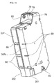
- Fig. 6 is a perspective view of the battery pack 19 accommodated in the battery pack cover 28, as viewed from a right upper rear side of the motorcycle 1.
- the battery pack cover 28 has a shape that would be obtained by removing one surface (the surface on the right side of the vehicle body) of six surfaces which constitute a substantially rectangular parallelepiped shape.
- a depth D (the dimension in the lateral direction of the vehicle body) of the battery pack cover 28 is so set that the battery pack cover 28 covers only roughly the left half 19L of the battery pack 19. Therefore, roughly a right half 19R of the battery pack 19 is not covered by the battery pack cover 28, so that the right-side external appearance of the battery pack 19 can be seen externally.
- the terminal base 29 is fixed to a bottom portion of the battery pack cover 28.
- the terminal base 29 is provided with a battery pack support part 295 which is engaged with a lower surface portion at a right side of the battery pack 19, namely, at its right half 19R (the half not covered with the battery pack cover 28).
- An upper portion of the right half 19R of the battery pack 19 extends above an upper end portion of the battery pack cover 28.
- This upper side extension 19P is provided with a recess which is recessed to the right from a part on the vehicle body left side.
- An upper wall forming the recess constitutes a grip part of the handle 34, and can be hooked by finger tips. The recess and the grip part constituting the upper wall of the recess will be described later, with particular reference to Figs. 10 and 13 .
- the battery case 20 of the battery pack 19 is composed of a front part 20F and a rear part 20Rr, such that the battery case 20 is bisected in the longitudinal direction of the vehicle.
- a front side surface of the front part 20F which forms the upper side extension 19P is formed with the engagement hole 62 in which the lock pin 323 projecting from the lock device 32 can be loosely fitted.
- the engagement hole 62 is formed in a wall surface of the front part 20F of the battery case 20, which is orthogonal to the grip part (described later) of the handle 34.
- Fig. 7 is a perspective view of the terminal base 29 fixed to the battery pack cover 28
- Fig. 8 is a perspective view of the terminal base 29 with an insulator board 64 fitted therein, as viewed from a right upper rear side of the vehicle body
- Fig. 9 is a perspective view of the terminal base 29 as viewed from a left lower rear side of the vehicle body.
- the terminal base 29 includes: a base 292 provided with an opening 291, into which can be fitted the insulator board 64 having mounted thereto a plurality of male terminals 63 arranged in a row in the longitudinal direction of the vehicle; mounting parts 293 and 294 protruding to the upper side of the base 292 and longitudinally spaced at a left side portion; and a battery pack support part 295 extending to the right in relation to the base 292. Between the opening 291 and the battery pack support part 295, a projecting part 29a for engagement with a bottom surface of the battery case 20 is formed on the base 292.
- the mounting parts 293 and 294 are provided with inner circumferential surfaces 29b and 29c (see Fig. 9 ), to be located over bosses 281 and 282 formed at a left side of the battery pack cover 28.
- the mounting parts 293 and 294 are formed with bolt holes 296 and 297 extending in the lateral direction of the vehicle. Bolts or setscrews (not shown) can be passed through the bolt holes 296 and 297 from the right and screw engaged with screw holes (not shown) formed in the bosses 281 and 282 protruding from the battery pack cover 28, so that the terminal base 29 can be fixed to the battery pack cover 28.
- upper guides 298, 298 are formed to project along the upper surface of the base 292.
- the right edge of the opening 291 is provided with a lower guide 299 located between the upper guides 298, 298, and formed to project along the lower surface of the base 292.
- a lower guide 301 is formed to project along the lower surface of the base 292.
- a stopper 300 projects from the upper surface of the base 292.
- a harness 65 is connected to the male terminals 63 and is led out towards the driving device 18.
- the harness 65 is passed through the opening 291 from the upper side of the base 292 of the terminal base 29 to the lower side of the base 292. Then, while clamping one edge (the right edge) of the insulator board 64 between the upper guides 298, 298 and the lower guide 299, the lower surface of another edge (the left edge) of the insulator board 64 is brought into contact with the lower guide 301, and the stopper 300 is engaged with the upper surface, thereby fixing it.
- the battery support part 295 is provided with two end engagement projections 59, 59 aligned in the longitudinal direction, and with a central engagement projection 66 located between the end engagement projections 59, 59.
- the central engagement projection 66 is provided with a peak portion 66P including a cylindrical stopper 66E projecting towards the sides of the end engagement projections 59, 59 and which engages with the battery case 20 as will be described later.
- ribs (described later) formed on a bottom portion of the battery case 20 are to be inserted.
- the upper portion shapes of the peak portions 59P and 66P of the end engagement projections 59, 59 and the central engagement projection 66 are the same circular arc shape, and they are aligned in the longitudinal direction of the battery pack 19.
- Right-side foot portions of the end engagement projections 59, 59 and the central engagement projection 66 form a shelf 67, whereby the end engagement projections 59, 59 and the central engagement projection 66 are interconnected at their lower portions.
- the shelf 67 provides a base on which the battery pack 19 can be tentatively put at the time of mounting or detaching the battery pack 19 to or from the battery pack cover 28.
- Fig. 10 is a perspective view of the battery pack 19 as viewed from a left upper rear side of the vehicle body
- Fig. 11 is a perspective view of the battery pack 19 as viewed from a left lower front side of the vehicle body.
- the front part 20F and the rear part 20Rr of the battery case 20 are coupled to each other by bolts or setscrews, to form the battery case 20 as a sealed casing.
- notches 68 as relief portions for passing bolts or setscrew therethrough are formed in a plurality of positions.
- screw holes 90 (described later with reference to Fig. 13 ) with which the bolts or setscrews passed from the front part 29F side are to be screw engaged are formed.
- notches 69 are formed at the circumference of the rear part 20Rr. The screw holes are formed in the part near the front part 20F exclusive of the notches 69.
- Lower corner parts 201 and 202 of the battery case 20 are recesses, which are cut out so as to avoid the mounting parts 293 and 294 formed on the terminal base 29. Further, at lower side surfaces (front and rear surfaces when the battery pack 19 is mounted on the vehicle) of the battery case 20, end engagement recesses 60 adapted to fit the end engagement projections 59, 59 of the battery support part 295 and a central engagement recess 70 adapted to fit the central engagement projection 66 of the battery support part 295 are formed.
- the end engagement recesses 60 and the central engagement recess 70 are partitioned by ribs 71 and 72 projecting from the bottom of the battery case 20.
- the ribs 71 and 72 are generally parallel to joint surfaces 20J of the front part 20F and the rear part 20Rr of the battery case 20.
- the ribs 71 and 72 each have two parts 711 and 712, and 721 and 722, and a step portion which is bent so as to extend orthogonal to the joint surfaces 20J.
- those parts 711 and 712 of the rib 71 and the parts 721 and 722 of the rib 72 make contact with the inside surfaces of the end engagement projections 59, 59.
- those parts 712 and 722 which are located on the inner side make contact with a downwardly extending outside portion of the peak portion 66P of the central engagement projection 66, and function as a guide for the battery pack 19 in relation to the terminal base 292.
- a link part 713 linking the parts 711 and 712 of the rib 71 to each other and a link part 723 linking the parts 721 and 722 of the rib 72 to each other are provided.
- the link parts 713 and 723 are each arc-shaped in side view of the battery pack 19 (a front or rear view with respect to the vehicle), and their inner circumferential surfaces (surfaces located near the upper side of the battery pack 19) are engaged with the stopper 66E of the central engagement projection 66 when the battery pack 19 is mounted on the terminal base 29.
- An insulator block 74 is mounted to a bottom portion of the battery case 20.
- the insulator block 74 is provided with female-side terminals 73 (described in detail later with reference to Figs. 24 to 26 etc.) into which can be inserted the male-side terminals 63 attached to the terminal base 29.
- the insulator block 74 is held between the front part 20F and the rear part 20Rr of the battery case 20, without using any fastening members such as bolts or setscrews. The mode of holding will be described later.
- the front part 20F of the battery case 20 is provided in its bottom portion with a cutout 75 into which can fit the projected part 29a formed on the terminal base 292.
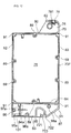
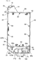
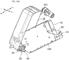
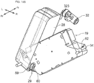
- Fig. 12 is a view of the front part 20F of the battery case 20, as viewed from the rear of the vehicle
- Fig. 13 is a view of the rear part 20Rr of the battery case 20, as viewed from the front of the vehicle
- Fig. 14 is a view of the battery case as viewed from the left side of the vehicle body.
- the front part 20F and the rear part 20Rr of the battery case 20 form an upper chamber 20U, a middle chamber 20M and a bottom chamber B (see Fig. 14 ) when combined with each other.
- Fig. 13 shows a condition where the insulator block 74 with the female-side terminals 73 accommodated therein is held in the bottom chamber 20B.
- the upper chamber 20U is formed as a recess which is surrounded by a front wall 76 and a rear wall 77, an upper wall 78 constituting the grip part of the handle 34, a vertical wall 79 extending downward from the upper wall 78, and an upper wall 80 of the middle chamber 20M, and which is opened on one side (the left side of the vehicle).
- the grip part, or the upper wall 78 has a partially cylindrical projection 781 which extends in the front-rear direction of the battery pack 19 (substantially the same direction as the longitudinal direction of the vehicle), which can be hooked by a user's fingers, and which projects downwards.
- the engagement hole 62 in which the lock pin can fit is formed in the front wall 76 of the front part 20F, at a position separated from the grip part 78.
- the middle chamber 20M is a chamber which can accommodate a plurality of battery cells (not shown).
- the middle chamber 20M is surrounded by the front wall 76 and the rear wall 77, the upper wall 80, left and right walls 82 and 83, and a bottom wall 84 (which is common with an upper wall of the bottom chamber 20B).
- the bottom chamber 20B is surrounded by the front wall 76 and the rear wall 77, the upper wall 84 (which is common with the bottom wall of the middle chamber 20M), a bottom wall 85, a left wall 86 and a right wall 87.
- the bottom chamber 20B is a chamber which can accommodate the female-side terminals 73, the insulator block 74, and a fuse 88.
- the fuse 88 will be described later, with reference to Fig. 17 .
- the front part 20F of the battery case 20 is provided with screw passing holes 89 through which bolts or setscrews can be passed.
- the rear part 20Rr of the battery case 20 is formed with screw holes 90 at positions corresponding to the screw passing holes 89.
- pins 91 for positioning are located on one of the front part 20F and the rear part 20Rr (here, the front part 20F) of the battery case 20, and the other (here, the rear part 20Rr) is formed with pin holes 92 in which the pins 91 can fit.
- the front part 20F of the battery case 20 forming the bottom chamber 20B is provided with: a rib 94a projecting from the upper wall 84 into the bottom chamber 20B; a rib 95a projecting from the left wall 86 into the bottom chamber 20B; a rib 96a projecting from the bottom wall 85 into the bottom chamber 20B; and a rib 97a projecting from the front wall 76 into the bottom chamber 20B.
- the rear part 20Rr of the battery case 20 which forms the bottom chamber 20B is provided with: a rib 94b projecting from the upper wall 84 into the bottom chamber 20B; a rib 95b projecting from the left wall 86 into the bottom chamber 20B; a rib 96b projecting from the bottom wall 85 into the bottom chamber 20B; and a rib 97b projecting from the rear wall 77 into the bottom chamber 20B.
- the ribs 95a and 95b, the ribs 96a and 96b, and the ribs 97a and 97b are located so as to face each other when the front part 20F and the rear part 20Rr are combined with each other; these ribs cooperate in holding the female-side terminals 73 and the insulator block 74 (described later).
- the front part 20F of the battery case 20 which forms the bottom chamber 20B is formed with a boss 98a projecting from the front wall 76.
- the rear part 20Rr of the battery case 20 is provided with ribs 98b, 99b, and 100b which project into the bottom chamber 20B from the upper wall 84 and the rear wall 77 forming the bottom chamber 20B.
- the ribs 98b, 99b and 100b cooperate with the boss 98B to hold a fuse 99 (described later) when the front part 20F and the rear part 20Rr are combined with each other.
- the front part 20F and the rear part 20Rr of the battery case 20 forming the bottom wall 85 of the bottom chamber 20B are formed respectively with cut-outs 101 and 102 for receiving an end portion of the insulator block 74.
- the cut-outs 101 and 102 form a substantially rectangular opening 103 (see Fig. 15 ) which can receive and hold an end portion of the insulator block 74.
- Fig. 15 is an enlarged view of a part of the battery case 20. As shown in Fig. 15 , the cut-outs 101 and 102 formed respectively in the joint surfaces 20J of the front part 20F and the rear part 20Rr form the opening 103 in a bottom portion of the battery case 20.
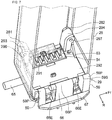
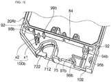
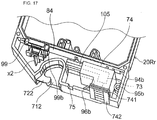
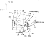
- Fig. 16 is an enlarged perspective view of a lower portion of the rear part 20Rr of the battery case 20
- Fig. 17 is an enlarged perspective view of a lower portion of the rear part 20Rr with the fuse 99 and the female-side terminals 73 and the insulator block 74 mounted in position.
- the ribs 94b, 95b and 96b each have a partially cylindrical shape, while the rib 97b is cross-shaped as viewed in the longitudinal direction of the vehicle.
- Ribs 98b and 99b extend in the longitudinal direction of the vehicle when the battery case 20 is mounted to the vehicle, and they are disposed parallel to each other.
- Rib 100b is composed of: a part x1 which is parallel to the ribs 98b, 99b and is shorter than the ribs 98b, 99b in height (the dimension along the longitudinal direction of the vehicle when the battery case 20 is mounted to the vehicle body); and a part x2 which has a greater height than the part x1 and is T-shaped as viewed in the longitudinal direction of the vehicle.
- the fuse 99 is seated on the part x1 of the rib 100, and is held between the ribs 98b, 99b and the T-shaped part x2 of the rib 100b.
- the insulator block 74 is seated on the rib 97b shown in Fig. 16 , and is held between the partially cylindrical members constituting the ribs 94b, 95b and 96b.
- the insulator block 74 holds the female-side terminals 73, and accommodates the harness 105 (composed of electric wires 771 and 772 and a signal line 773) which is led out towards the fuse 99.
- the insulator block 74 is provided with flange parts 741 and 742, by means of which the circumferential edge of the opening 103 (formed by the combination of the cut-outs 101 and 102 in the bottom wall 85 of the battery case 20) is clamped from the inside and the outside of the bottom chamber 20B.
- the outer circumferential shape of that part 743 of the insulator block 74 located between the flanges 741 and 742 is set to have such dimensions as to fit the inner circumference of the opening 103.
- the fuse 99 and the insulator block 74 are simultaneously held in the battery case 20 by combination or assembly of the front part 20F and the rear part 20Rr of the battery case 20, without using any additional fastening parts such as bolts or setscrews.
- FIGs. 18A to 18D are views from the rear of the vehicle showing the positional relationship between the battery pack 19 and the terminal base 29 at the time of mounting the battery pack 19 to the battery pack cover 28.
- Figs. 19A to 19D are views showing the positional relationship between the battery pack cover 28 as well as the terminal base 29 and the battery pack 19, as viewed from a right upper rear side of the vehicle body, corresponding respectively to Figs. 18A to 18D .
- the motorcycle 1 is left standing in a leftwardly inclined posture by use of the side stand. Therefore, the terminal base 29 is not set upright but is inclined to the left by an angle of about 12 degrees, for example. For simplification, however, the motorcycle 1 is shown upright in Figs. 18A to 18D and Figs. 19A to 19D .
- the battery pack support part 295 composed of the end engagement projections 59, 59 and the central engagement projection 66 has slant surfaces 59d, 66d formed to slant down toward the right side of the vehicle from a peak portion 29P (composed of the peak portions 59P, 66P).
- the slant surfaces 59d, 66d have an angle ⁇ relative to the base 292, and the angle ⁇ may, for example, be 35 degrees).
- the battery pack 19 is brought closer to the terminal base 29 from a right upper side of the vehicle. It is recommended that the user grips the handle 34 with the right hand and supports the part 19R, on the side where the handle 34 is formed, with the left hand.
- the battery pack 19 is brought closer to the terminal base 29 in such a manner that the vertical walls of the end engagement recesses 60 and the central engagement recess 70 formed by the rib 71 and the rib 72 provided at a bottom portion of the battery case 20 (the vertical wall 601 of the end engagement recess 60 is taken as a representative of these vertical walls in the description here) are directed substantially along the slant surfaces 59d, 66d of the battery pack support part 295, and the peak portion 29P of the battery pack support part 295 is opposed to the end engagement recesses 60 and the central engagement recess 70 from the lower side of the battery pack 19.
- the rib 71 is composed of the parts 711 and 712, while the rib 72 is composed of the parts 721 and 722.
- the peak portion of the battery pack support part 295 is composed of the peak portions 59P and 66P.
- the battery pack cover 28 is only covers one side of the terminal base 29 (the side on the left of the vehicle and on which the male-side terminals 63 are provided), and does not cover the battery pack support part 295. This allows the user to clearly recognize visually the positional relationship between the end engagement projections 59 and the end engagement recesses 60.
- the hand supporting the battery pack 19 is slightly loosened.
- the battery pack 19 slides downward on the vertical wall 601 along the slant surfaces 59d, 66d, to be moved into the position as shown in Figs. 18B and 19B .
- the peak portion 29P of the battery pack support part 295 has reached the uppermost portions of the end engagement recesses 60.
- a surface 19c formed by cutting a corner of a bottom portion of the battery pack 19 makes contact with the upper surface of the shelf 67 of the battery pack support part 295.
- the battery pack 19 (which has been tentatively placed in the inclined posture) is tilted up toward the left side of the vehicle, to be put into an upright state.
- the position of the battery pack 19 relative to the terminal base 29 is changed with corner portions 60a of the end engagement recesses 60 acting as fulcrums, and the surface 19c is separated from the shelf 67 of the terminal base 29.
- the male-side terminals 63 projecting upwardly from the terminal base 29 start being engaged with the insulator block 74 accommodating the female-side terminals 73 of the battery pack 19.
- the tips of the male-side terminals 63 are bevelled on the left side relative to the vehicle (on the depth side in the battery insertion direction). This ensures that the tips of the male-side terminals 63 are prevented from abutting against a corner portion of the opening of the insulator block 74 (a corner portion of the opening by which the male-side terminals 63 are guided to an insertion port for insertion into the female-side terminals 73).
- the detailed shape of the male-side terminals 63 will be described later with reference to Figs. 21 and 23 , etc.
- the battery pack 19 is seated on the terminal base 29.
- the bottom surface of the battery pack 19 is in contact with the upper surface of the base 292, and the male-side terminals 63 are in electrical contact with the female-side terminals 73.
- the engagement hole 62 formed in the front wall 76 of the handle 34 of the battery pack 19 faces the lock pin 323 of the lock device 32.
- the lock pin 323 protrudes and fits into the engagement hole 62.
- the battery pack 19 situated on the terminal base 29 is locked to the main frame 3 of the motorcycle 1.
- the stopper 66E projecting from the peak portion 66P of the central engagement projection 66 of the battery pack support part 295 is in engagement with the inner circumferential surfaces (upper side surfaces) of the link part 713 between the parts 711 and 712 of the rib 71 and the link part 723 between the parts 721 and 722 of the rib 72. This ensures that the battery pack 19 is restrained in position in the vertical direction.
- the position of the battery pack 19 on the terminal base 29 in the direction parallel to the upper surface of the base 292 is restrained by those contact portions of the end engagement recesses 60, 60 and the central engagement recess 70 which make contact with the end engagement projections 59, 59 and the central engagement projection 66.
- the position is also restrained by the fitting between the cutout 75 formed in a bottom portion of the front part 20F of the battery case 20 and the projecting part 29a on the terminal base 29.
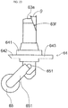
- Fig. 20 is a view of a male-side terminal unit from the right side of the vehicle body
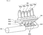
- Fig. 21 is a perspective view of the male-side terminal unit from a rear right lower side of the vehicle body
- Fig. 22 is a plan view of the male-side terminal unit
- Fig. 23 is a view of the male-side terminal unit from the front side of the vehicle body.
- a plurality of male-side terminals 63 here, five are provided, and they are arrayed in the longitudinal direction of the vehicle.
- the power terminals 63a, 63e are disposed such that their tips are located above the tips of the signal line terminals 63b, 63c, 63d. In other words, the power terminals 63a, 63e are set to have a greater projection length than the signal line terminals 63b, 63c, 63d. This ensures that at the time of terminal connection, signal circuits are connected after the power supply is connected.
- the dimensions of the power terminals 63a, 63e are determined taking heat capacity into consideration.
- the signal line terminals 63b 63c, 63d may have dimensions which are the same as those of the power terminals 63a, 63e, or may be smaller than the power terminals 63a, 63e.
- the corner 63f on the left side relative to the vehicle is obliquely cut at an angle ⁇ relative to the lengthwise direction of the male-side terminal 63; thus, the tip is tapered off as viewed from the rear of the vehicle.
- the number of signal line terminals is not limited to three, and may be increased or decreased, as required. Alternatively, the number of the signal line terminals may be fixed, for example, to five, and all or some of them may be used according to situations, for example, the model and type of the motorcycle 1.
- the male-side terminal 63 is provided to orthogonally penetrate the insulator board 64. Electric wires 651 and 652 or signal lines 653, 653, 653 branched from the harness 65 are connected to the portion of the male-side terminal 63 which is located below the insulator board 64.
- the insulator board 64 includes a main part 641 to be fitted into the opening 291 formed in the terminal base 29, a right-side edge 642 projecting from the main part 641 towards the right relative to the vehicle, which is to be clamped between the main part 641 and the upper guides 298 of the terminal base 29, and a left-side edge 643 projecting from the main part 641 towards the left relative to the vehicle, which is to be engaged with the stopper 300 extending from the terminal base 29.
- the left-side edge 643 is formed with a recess 644.
- the tip of the stopper 300 comes around to the upper side of the lower guide 301 of the insulator board 64 while avoiding the recess 644.
- the insulator board 64 is fixed by being clamped between the stopper 300 and the lower guide 301 of the terminal base 29 (see also Figs. 8 and 9 ).
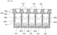
- Fig. 24 is a perspective view of the insulator block 74 with the female-side terminals 73 accommodated therein, as viewed from a right lower front side of the vehicle body
- Fig. 25 is a perspective view of the same as viewed from a left upper rear side
- Fig. 26 is a sectional view of the insulator block 74, as viewed from a left side of the vehicle body, showing contact parts of the female-side terminals 73.
- the insulator block 74 is formed in its upper portion with a plurality openings 745 (here, five) in which to insert the plurality of male-side terminals 63 (63a to 63e).
- the opening 745 is rectangular in cross-section, and has taper surfaces such that the area of the aperture reduces with increasing depth.
- the female-side terminal 73 is located on the narrower side of the opening 745.
- the female-side terminal 73 has a connection part 633 which extends from two connection parts 632 and 632, which can clamp the inserted male-side terminal 63 from two sides (as shown in Fig. 26 ), and which is connected to electric wires 771 and 772 or a signal line 773.
- flange parts 741 and 742 are formed, by means of which the circumferential edge of the opening 103 formed in the bottom portion of the battery case 20 is clamped from the inside and the outside of the bottom chamber 20B.
- the part 743 located between the flange parts 741 and 742 has dimensions which allow it to conform to the inner edge of the opening 103.
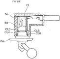
- Figs. 27A to 27E are sectional views showing the positional relationship between the male-side terminal 63 and the female-side terminal 73, as viewed from the rear side of the vehicle body.
- the insulator block 74 with the female-side terminal 73 accommodated therein is brought closer to the male-side terminal 63 from a right upper side of the vehicle body.
- the tip of the male-side terminal 63 is in such a position that it is partly inserted into the insulator block 74. Since the opening 745 of the insulator block 74 is formed with a taper, a large clearance CL1 is maintained between the corner 63f formed by obliquely cutting the tip of the male-side terminal 63 and the insulator block 74.
- the tip of the male-side terminal 63 is in contact with the end portion of the female-side terminal 73 inside the insulator block 74 which is closest to the opening 745.
- the corner 63f of the male-side terminal 63 and the taper surface of the opening 745 of the insulator block 74 are roughly parallel to each other.
- a tip portion of the male-side terminal 63 is shaped so that plate thickness decreases toward the tipmost portion.
- a ridgeline 63h exists at the boundary between the thinned portion and the portion where the plate thickness is maintained.
- the ridgeline 63h at the tip portion of the male-side terminal 63 and the end portion 731 of the female-side terminal 73 are roughly parallel to each other.
- the clearance CL2 between the corner 63f of the male-side terminal 63 and the insulator block 74 is smaller than the clearance CL1.
- the male-side terminal 63 and the insulator block 74 are not in contact with each other.
- Fig. 27E there is shown a connected state where the battery pack 19 is mounted on the terminal base 29 in the position as shown in Fig. 18D .
- the male-side terminal 63 has entered into the female-side terminal 73, and the connection has been completed.
- clearances CL3 and CL4 are maintained between the male-side terminal 63 and the insulator block 74.
- clearances CL5 and CL6 are also maintained, but these are smaller than the clearances CL3 and CL4.
- Fig. 28 is an enlarged view of a part of Fig. 27E , and shows these clearances in more detail.
- the handle 34 formed on the upper portion of the battery case 20 is offset toward the right side of the battery pack 19. Therefore, the middle chamber 20M (the battery cell accommodating part) can be located just under the main frame 3 of the motorcycle 1, while the handle 34 itself is located to the right side of the main frame 3 and can be raised up to such a position as to overlap with the main frame 3 in a side view of the vehicle body. With the handle 34 thus located at an upper position, the middle chamber 20M can be enlarged, and more battery cells can be accommodated therein.
- main frame 3 of the motorcycle 1 is a monocoque-type frame, the frame is not restricted to this design.
- An under frame extending downward from the head pipe 2 to be joined at its rear end to lower end portions of the pivot plates 4 may be provided.
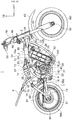
- Fig. 29 is a right side view of the motorcycle 1 provided with an under frame.
- a skid plate 106 is provided on the front of the under frame 105.
- the skid plate 106 covers at least a front lower side of the battery pack 19.
- the under frame 105 is provided, as shown in Fig. 29 , the PDU 33 can be mounted to the under frame 105 instead of to the bracket 31.
- a lock device support stay 30 for fixing the lock device 32 can extend toward the rear of the vehicle to form a part 30a, and an upper portion of the battery pack cover 28 can be connected by the thus extended part 30a.
- the battery cover 28 can be supported at its lower portion by the battery pack holding stay 27 extending from the motor case 23, and at its upper portion by the lock device support stay 30.
- the lock device 32 is not restricted to one wherein the lock pin is advanced and retracted manually.
- a configuration may be adopted wherein the lock pin can be actuated by an actuator such as a solenoid or a motor, and the actuator is controlled remotely by use of an electronic key or keys.
- the lock device 32 is not restricted to one that is disposed at a front portion of the battery pack 19.
- the lock device 32 may be disposed on the vehicle body rear side in relation to the battery pack 19.
- the engagement hole 62 for the lock pin 323 is not provided on the side of the front part 20F of the battery case 20 but is instead provided on the side of the rear part 20Rr of the battery case 20.
Claims (6)
- Véhicule électrique avec un dispositif d'alimentation électrique qui comprend un compartiment de batterie (20) servant au logement de cellules de batterie pour l'alimentation en énergie électrique d'un moteur électrique (21) du véhicule électrique (1) et qui peut être monté sur le véhicule électrique (1) et détaché de celui-ci,
dans lequel le compartiment de batterie (20) présente une partie (19P) s'étendant jusqu'au-dessus d'une partie de logement de cellule de batterie ;
la partie d'extension (19P) est dotée d'un manche (34) incluant une partie de préhension (78) agencée de sorte à s'étendre dans la direction longitudinale du véhicule lorsque le dispositif d'alimentation électrique est monté sur le véhicule électrique (1) ; et
une partie de mise en prise (62) pour la mise en prise avec une partie mobile (323) d'un dispositif de verrouillage (32) attaché au véhicule électrique (1) est formée sur la surface avant ou la surface arrière du manche (34) ;
caractérisé en ce que le véhicule électrique (1) inclut :un cadre principal (3) d'un type monocoque qui présente une forme courbée vers le haut ;un pivot (5) par lequel une extrémité avant d'un bras oscillant (7) est supportée sur le cadre principal (3) ;le moteur électrique (21) disposé à l'avant du pivot (5) ; etune unité d'entraînement électrique (33) disposée à l'avant du moteur électrique (21),le dispositif d'alimentation électrique étant disposé entre le moteur électrique (21) et l'unité d'entraînement électrique (33) ;
dans lequel la partie d'extension (19P) est en déport vers la gauche ou la droite du compartiment de batterie (20) lorsque le compartiment de batterie (20) est monté sur le véhicule électrique (1), et
au moins une portion supérieure de la partie d'extension (19P) s'étend de sorte à recouvrir, en vue de côté du véhicule, la portion du cadre principal (3) qui est située au-dessus du compartiment de batterie (20). - Véhicule électrique avec un dispositif d'alimentation électrique selon la revendication 1, dans lequel la partie mobile (323) du dispositif de verrouillage (32) est une goupille de verrouillage (323) qui peut être avancée et rétractée dans la direction longitudinale du véhicule électrique (1) par rapport au dispositif de verrouillage (32), et la partie de mise en prise (62) est un trou de mise en prise (62) pour la réception de la goupille de verrouillage (323).
- Véhicule électrique avec un dispositif d'alimentation électrique selon la revendication 1, comprenant :un carter moteur (23) dans lequel le moteur électrique (21) est logé et qui est supporté sur le cadre principal (3) ;une base de borne (29) incorporant une borne côté mâle (63) qui peut être couplée à une borne côté femelle (73) disposée sur une portion inférieure du compartiment de batterie (20) ;un couvercle de bloc-batterie (28), doté de la base de borne (29) sur une portion inférieure de celui-ci, et présentant un espace de sorte que le compartiment de batterie (20) puisse être disposé sur la base de borne (29) ; etun étai de support de bloc-batterie (27) pour le raccordement du couvercle de batterie (28) au carter moteur (23).
- Véhicule électrique avec un dispositif d'alimentation électrique selon la revendication 3,
dans lequel un étai de support de dispositif de verrouillage (30) est joint au cadre principal (3) et supporte le dispositif de verrouillage (32), et
l'étai de support de dispositif de verrouillage (30) présente une partie d'extension (30a) qui s'étend de sorte à être couplée à une portion supérieure du couvercle de bloc-batterie (28). - Véhicule électrique avec un dispositif d'alimentation électrique selon la revendication 1,
dans lequel le cadre principal (3) du véhicule électrique (1) présente un cadre inférieur (105) étendu vers le bas en face du couvercle de bloc-batterie (28), et
une plaque à coulisse (106) est attachée au cadre inférieur (105) ; - Véhicule électrique avec un dispositif d'alimentation électrique selon la revendication 2, dans lequel un anneau (621) est inséré dans une surface circonférentielle intérieure du trou de mise en prise (62) et sert d'élément de renforcement.
Applications Claiming Priority (1)
| Application Number | Priority Date | Filing Date | Title |
|---|---|---|---|
| JP2012026128A JP5999914B2 (ja) | 2012-02-09 | 2012-02-09 | 電動車両用電源装置 |
Publications (3)
| Publication Number | Publication Date |
|---|---|
| EP2626230A2 EP2626230A2 (fr) | 2013-08-14 |
| EP2626230A3 EP2626230A3 (fr) | 2014-09-17 |
| EP2626230B1 true EP2626230B1 (fr) | 2019-05-15 |
Family
ID=47664202
Family Applications (1)
| Application Number | Title | Priority Date | Filing Date |
|---|---|---|---|
| EP13154354.8A Active EP2626230B1 (fr) | 2012-02-09 | 2013-02-07 | Dispositif d'alimentation électrique pour véhicule électrique |
Country Status (8)
| Country | Link |
|---|---|
| US (1) | US9248792B2 (fr) |
| EP (1) | EP2626230B1 (fr) |
| JP (1) | JP5999914B2 (fr) |
| AU (1) | AU2012254932B2 (fr) |
| BR (1) | BR102013003090A2 (fr) |
| CA (1) | CA2798288C (fr) |
| IN (1) | IN2013CH00479A (fr) |
| TW (1) | TWI541164B (fr) |
Cited By (1)
| Publication number | Priority date | Publication date | Assignee | Title |
|---|---|---|---|---|
| DE102022132461B3 (de) | 2022-12-07 | 2024-02-01 | Dr. Ing. H.C. F. Porsche Aktiengesellschaft | Batterieanordnung, Fahrzeug und Verfahren |
Families Citing this family (19)
| Publication number | Priority date | Publication date | Assignee | Title |
|---|---|---|---|---|
| JP5603504B2 (ja) * | 2011-10-28 | 2014-10-08 | 川崎重工業株式会社 | 鞍乗型電動車両 |
| AU2013251183B1 (en) * | 2013-10-29 | 2014-12-11 | Lee, Roger Bruce MR | Battery isolator covering original battery terminal(s) with lock out facility being fully water - dust and chemical resistant. |
| JP6399741B2 (ja) * | 2013-11-06 | 2018-10-03 | ヤマハ発動機株式会社 | 鞍乗型電動車両 |
| JP2015089756A (ja) | 2013-11-06 | 2015-05-11 | ヤマハ発動機株式会社 | 鞍乗型電動車両 |
| JP6245946B2 (ja) | 2013-11-06 | 2017-12-13 | ヤマハ発動機株式会社 | バッテリ及びそれを備えた鞍乗型電動車両 |
| JP6284746B2 (ja) | 2013-11-06 | 2018-02-28 | ヤマハ発動機株式会社 | 鞍乗型電動車両 |
| JP6617074B2 (ja) * | 2016-05-16 | 2019-12-04 | 本田技研工業株式会社 | 電動車両 |
| JP2018088853A (ja) * | 2016-11-30 | 2018-06-14 | 本田技研工業株式会社 | 電動作業機 |
| CN107416099A (zh) * | 2017-08-30 | 2017-12-01 | 浙江杭派电动车有限公司 | 一种便于拆卸电瓶的电动车车架 |
| WO2019064556A1 (fr) * | 2017-09-29 | 2019-04-04 | 本田技研工業株式会社 | Dispositif de stockage de batterie pour véhicule |
| US11355812B2 (en) * | 2017-09-29 | 2022-06-07 | Honda Motor Co., Ltd. | Battery storage device of vehicle |
| CN108100149B (zh) * | 2017-12-20 | 2024-04-16 | 上海钧正网络科技有限公司 | 自行车智能车锁及其控制系统 |
| KR102359015B1 (ko) * | 2017-12-29 | 2022-02-08 | 상하이 디안바 뉴 에너지 테크놀러지 코., 엘티디. | 배터리 홀더, 배터리 교체 장치, 전기 자동차, 및 전기 자동차의 설치 방법. |
| JP6908557B2 (ja) * | 2018-05-18 | 2021-07-28 | 株式会社シマノ | ロック装置、バッテリユニット、および、バッテリホルダ |
| JP6894401B2 (ja) * | 2018-05-18 | 2021-06-30 | 株式会社シマノ | ロック装置 |
| DE102018212574B3 (de) * | 2018-07-27 | 2019-09-05 | Robert Bosch Gmbh | Haltesystem für einen Energiespeicher sowie Zweirad mit diesem Haltesystem |
| WO2020140089A1 (fr) | 2018-12-27 | 2020-07-02 | Uber Technologies, Inc. | Batterie rechargeable et réceptacle de batterie rechargeable pour véhicules électriques légers |
| US11565769B2 (en) | 2020-12-11 | 2023-01-31 | Specialized Bicycle Components, Inc. | 3-position battery latching system |
| JPWO2022209955A1 (fr) * | 2021-03-31 | 2022-10-06 |
Family Cites Families (19)
| Publication number | Priority date | Publication date | Assignee | Title |
|---|---|---|---|---|
| JPS6159186U (fr) * | 1984-09-13 | 1986-04-21 | ||
| JPH07329858A (ja) * | 1994-06-11 | 1995-12-19 | Honda Motor Co Ltd | 電動補助自転車のバッテリ着脱構造 |
| JPH0995291A (ja) | 1995-10-02 | 1997-04-08 | Yamaha Motor Co Ltd | 車両用バッテリ収納装置 |
| JP3682734B2 (ja) * | 1996-02-29 | 2005-08-10 | ヤマハ発動機株式会社 | 電動自転車 |
| JPH10181651A (ja) * | 1996-12-26 | 1998-07-07 | Yamaha Motor Co Ltd | 電動自転車のバッテリボックス固定構造 |
| JPH10230881A (ja) * | 1997-02-21 | 1998-09-02 | Sanyo Electric Co Ltd | 電気自転車 |
| CA2246590A1 (fr) * | 1997-09-16 | 1999-03-16 | Sanyo Electric Co., Ltd. | Bicyclette a entrainement electrique |
| JP4301421B2 (ja) * | 1999-10-13 | 2009-07-22 | 本田技研工業株式会社 | 補助動力付き自転車のバッテリ施錠装置 |
| JP4325820B2 (ja) * | 1999-10-13 | 2009-09-02 | 本田技研工業株式会社 | 電動補助自転車 |
| JP3949446B2 (ja) * | 2001-12-20 | 2007-07-25 | 本田技研工業株式会社 | 電動車両のバッテリ配置構造 |
| JP2003231493A (ja) | 2002-02-12 | 2003-08-19 | Sanyo Electric Co Ltd | 電動自転車 |
| JP4274759B2 (ja) | 2002-08-16 | 2009-06-10 | ヤマハ発動機株式会社 | 電動二輪車 |
| JP4762652B2 (ja) * | 2005-09-15 | 2011-08-31 | 川崎重工業株式会社 | 自動二輪車の車体フレーム |
| US7413045B2 (en) * | 2005-11-30 | 2008-08-19 | Karma Medical Products Co., Ltd. | Battery quick-release structure for an electric mobility scooter |
| US20090252994A1 (en) * | 2008-04-04 | 2009-10-08 | Alexander Livingston | Battery pack system |
| US8653786B2 (en) * | 2008-04-25 | 2014-02-18 | Black & Decker Inc. | Cordless mower including battery with two charging connectors |
| US7963344B2 (en) * | 2008-09-03 | 2011-06-21 | Black & Decker Inc. | Tiller with removable battery |
| US8146694B2 (en) * | 2009-01-20 | 2012-04-03 | Vahid Hamidi | Swappable modulated battery packs system for electrically driven vehicle |
| JP5593894B2 (ja) * | 2009-07-30 | 2014-09-24 | スズキ株式会社 | 電動の乗り物に脱着されるバッテリパックとこのバッテリパックを備える電動の乗り物 |
-
2012
- 2012-02-09 JP JP2012026128A patent/JP5999914B2/ja active Active
- 2012-11-16 AU AU2012254932A patent/AU2012254932B2/en not_active Ceased
- 2012-12-07 CA CA2798288A patent/CA2798288C/fr not_active Expired - Fee Related
- 2012-12-10 TW TW101146341A patent/TWI541164B/zh not_active IP Right Cessation
- 2012-12-19 US US13/720,491 patent/US9248792B2/en active Active
-
2013
- 2013-02-04 IN IN479CH2013 patent/IN2013CH00479A/en unknown
- 2013-02-07 EP EP13154354.8A patent/EP2626230B1/fr active Active
- 2013-02-07 BR BRBR102013003090-2A patent/BR102013003090A2/pt not_active Application Discontinuation
Non-Patent Citations (1)
| Title |
|---|
| None * |
Cited By (1)
| Publication number | Priority date | Publication date | Assignee | Title |
|---|---|---|---|---|
| DE102022132461B3 (de) | 2022-12-07 | 2024-02-01 | Dr. Ing. H.C. F. Porsche Aktiengesellschaft | Batterieanordnung, Fahrzeug und Verfahren |
Also Published As
| Publication number | Publication date |
|---|---|
| JP5999914B2 (ja) | 2016-09-28 |
| US20130207460A1 (en) | 2013-08-15 |
| JP2013163399A (ja) | 2013-08-22 |
| BR102013003090A2 (pt) | 2015-06-16 |
| CA2798288A1 (fr) | 2013-08-09 |
| AU2012254932A1 (en) | 2013-08-29 |
| EP2626230A2 (fr) | 2013-08-14 |
| TW201332831A (zh) | 2013-08-16 |
| TWI541164B (zh) | 2016-07-11 |
| CA2798288C (fr) | 2014-12-02 |
| US9248792B2 (en) | 2016-02-02 |
| IN2013CH00479A (fr) | 2015-07-31 |
| AU2012254932B2 (en) | 2015-02-12 |
| EP2626230A3 (fr) | 2014-09-17 |
Similar Documents
| Publication | Publication Date | Title |
|---|---|---|
| EP2626230B1 (fr) | Dispositif d'alimentation électrique pour véhicule électrique | |
| CA2798658C (fr) | Dispositif d'alimentation en electricite pour un vehicule electrique | |
| EP2626233B1 (fr) | Base de borne de dispositif d'alimentation pour un véhicule électrique | |
| US9093701B2 (en) | Terminal base of power supply device for electric vehicle | |
| EP2626231B1 (fr) | Dispositif d'alimentation électrique pour véhicule électrique | |
| EP2626232B1 (fr) | Dispositif d'alimentation électrique pour un véhicule électrique | |
| US9373828B2 (en) | Power supply device for electric vehicle | |
| EP2799320B1 (fr) | Véhicule électrique à selle | |
| JP2001097275A (ja) | 電動補助自転車のバッテリ取付構造 | |
| JP2017190071A (ja) | 鞍乗型電動車両 | |
| JPH11115871A (ja) | 電動自転車のバッテリボックスロック構造 | |
| EP4094973A1 (fr) | Dispositif de stockage de batterie et véhicule électrique |
Legal Events
| Date | Code | Title | Description |
|---|---|---|---|
| PUAI | Public reference made under article 153(3) epc to a published international application that has entered the european phase |
Free format text: ORIGINAL CODE: 0009012 |
|
| 17P | Request for examination filed |
Effective date: 20130207 |
|
| AK | Designated contracting states |
Kind code of ref document: A2 Designated state(s): AL AT BE BG CH CY CZ DE DK EE ES FI FR GB GR HR HU IE IS IT LI LT LU LV MC MK MT NL NO PL PT RO RS SE SI SK SM TR |
|
| AX | Request for extension of the european patent |
Extension state: BA ME |
|
| PUAL | Search report despatched |
Free format text: ORIGINAL CODE: 0009013 |
|
| AK | Designated contracting states |
Kind code of ref document: A3 Designated state(s): AL AT BE BG CH CY CZ DE DK EE ES FI FR GB GR HR HU IE IS IT LI LT LU LV MC MK MT NL NO PL PT RO RS SE SI SK SM TR |
|
| AX | Request for extension of the european patent |
Extension state: BA ME |
|
| RIC1 | Information provided on ipc code assigned before grant |
Ipc: B60L 11/18 20060101AFI20140812BHEP |
|
| GRAP | Despatch of communication of intention to grant a patent |
Free format text: ORIGINAL CODE: EPIDOSNIGR1 |
|
| STAA | Information on the status of an ep patent application or granted ep patent |
Free format text: STATUS: GRANT OF PATENT IS INTENDED |
|
| INTG | Intention to grant announced |
Effective date: 20181121 |
|
| GRAS | Grant fee paid |
Free format text: ORIGINAL CODE: EPIDOSNIGR3 |
|
| GRAA | (expected) grant |
Free format text: ORIGINAL CODE: 0009210 |
|
| STAA | Information on the status of an ep patent application or granted ep patent |
Free format text: STATUS: THE PATENT HAS BEEN GRANTED |
|
| AK | Designated contracting states |
Kind code of ref document: B1 Designated state(s): AL AT BE BG CH CY CZ DE DK EE ES FI FR GB GR HR HU IE IS IT LI LT LU LV MC MK MT NL NO PL PT RO RS SE SI SK SM TR |
|
| REG | Reference to a national code |
Ref country code: CH Ref legal event code: EP Ref country code: GB Ref legal event code: FG4D |
|
| REG | Reference to a national code |
Ref country code: DE Ref legal event code: R096 Ref document number: 602013055324 Country of ref document: DE |
|
| REG | Reference to a national code |
Ref country code: IE Ref legal event code: FG4D |
|
| REG | Reference to a national code |
Ref country code: NL Ref legal event code: MP Effective date: 20190515 |
|
| REG | Reference to a national code |
Ref country code: LT Ref legal event code: MG4D |
|
| PG25 | Lapsed in a contracting state [announced via postgrant information from national office to epo] |
Ref country code: FI Free format text: LAPSE BECAUSE OF FAILURE TO SUBMIT A TRANSLATION OF THE DESCRIPTION OR TO PAY THE FEE WITHIN THE PRESCRIBED TIME-LIMIT Effective date: 20190515 Ref country code: NO Free format text: LAPSE BECAUSE OF FAILURE TO SUBMIT A TRANSLATION OF THE DESCRIPTION OR TO PAY THE FEE WITHIN THE PRESCRIBED TIME-LIMIT Effective date: 20190815 Ref country code: PT Free format text: LAPSE BECAUSE OF FAILURE TO SUBMIT A TRANSLATION OF THE DESCRIPTION OR TO PAY THE FEE WITHIN THE PRESCRIBED TIME-LIMIT Effective date: 20190915 Ref country code: ES Free format text: LAPSE BECAUSE OF FAILURE TO SUBMIT A TRANSLATION OF THE DESCRIPTION OR TO PAY THE FEE WITHIN THE PRESCRIBED TIME-LIMIT Effective date: 20190515 Ref country code: AL Free format text: LAPSE BECAUSE OF FAILURE TO SUBMIT A TRANSLATION OF THE DESCRIPTION OR TO PAY THE FEE WITHIN THE PRESCRIBED TIME-LIMIT Effective date: 20190515 Ref country code: SE Free format text: LAPSE BECAUSE OF FAILURE TO SUBMIT A TRANSLATION OF THE DESCRIPTION OR TO PAY THE FEE WITHIN THE PRESCRIBED TIME-LIMIT Effective date: 20190515 Ref country code: NL Free format text: LAPSE BECAUSE OF FAILURE TO SUBMIT A TRANSLATION OF THE DESCRIPTION OR TO PAY THE FEE WITHIN THE PRESCRIBED TIME-LIMIT Effective date: 20190515 Ref country code: LT Free format text: LAPSE BECAUSE OF FAILURE TO SUBMIT A TRANSLATION OF THE DESCRIPTION OR TO PAY THE FEE WITHIN THE PRESCRIBED TIME-LIMIT Effective date: 20190515 Ref country code: HR Free format text: LAPSE BECAUSE OF FAILURE TO SUBMIT A TRANSLATION OF THE DESCRIPTION OR TO PAY THE FEE WITHIN THE PRESCRIBED TIME-LIMIT Effective date: 20190515 |
|
| PG25 | Lapsed in a contracting state [announced via postgrant information from national office to epo] |
Ref country code: RS Free format text: LAPSE BECAUSE OF FAILURE TO SUBMIT A TRANSLATION OF THE DESCRIPTION OR TO PAY THE FEE WITHIN THE PRESCRIBED TIME-LIMIT Effective date: 20190515 Ref country code: GR Free format text: LAPSE BECAUSE OF FAILURE TO SUBMIT A TRANSLATION OF THE DESCRIPTION OR TO PAY THE FEE WITHIN THE PRESCRIBED TIME-LIMIT Effective date: 20190816 Ref country code: LV Free format text: LAPSE BECAUSE OF FAILURE TO SUBMIT A TRANSLATION OF THE DESCRIPTION OR TO PAY THE FEE WITHIN THE PRESCRIBED TIME-LIMIT Effective date: 20190515 Ref country code: BG Free format text: LAPSE BECAUSE OF FAILURE TO SUBMIT A TRANSLATION OF THE DESCRIPTION OR TO PAY THE FEE WITHIN THE PRESCRIBED TIME-LIMIT Effective date: 20190815 |
|
| REG | Reference to a national code |
Ref country code: AT Ref legal event code: MK05 Ref document number: 1133016 Country of ref document: AT Kind code of ref document: T Effective date: 20190515 |
|
| PG25 | Lapsed in a contracting state [announced via postgrant information from national office to epo] |
Ref country code: RO Free format text: LAPSE BECAUSE OF FAILURE TO SUBMIT A TRANSLATION OF THE DESCRIPTION OR TO PAY THE FEE WITHIN THE PRESCRIBED TIME-LIMIT Effective date: 20190515 Ref country code: EE Free format text: LAPSE BECAUSE OF FAILURE TO SUBMIT A TRANSLATION OF THE DESCRIPTION OR TO PAY THE FEE WITHIN THE PRESCRIBED TIME-LIMIT Effective date: 20190515 Ref country code: CZ Free format text: LAPSE BECAUSE OF FAILURE TO SUBMIT A TRANSLATION OF THE DESCRIPTION OR TO PAY THE FEE WITHIN THE PRESCRIBED TIME-LIMIT Effective date: 20190515 Ref country code: AT Free format text: LAPSE BECAUSE OF FAILURE TO SUBMIT A TRANSLATION OF THE DESCRIPTION OR TO PAY THE FEE WITHIN THE PRESCRIBED TIME-LIMIT Effective date: 20190515 Ref country code: DK Free format text: LAPSE BECAUSE OF FAILURE TO SUBMIT A TRANSLATION OF THE DESCRIPTION OR TO PAY THE FEE WITHIN THE PRESCRIBED TIME-LIMIT Effective date: 20190515 Ref country code: SK Free format text: LAPSE BECAUSE OF FAILURE TO SUBMIT A TRANSLATION OF THE DESCRIPTION OR TO PAY THE FEE WITHIN THE PRESCRIBED TIME-LIMIT Effective date: 20190515 |
|
| REG | Reference to a national code |
Ref country code: DE Ref legal event code: R097 Ref document number: 602013055324 Country of ref document: DE |
|
| PG25 | Lapsed in a contracting state [announced via postgrant information from national office to epo] |
Ref country code: IT Free format text: LAPSE BECAUSE OF FAILURE TO SUBMIT A TRANSLATION OF THE DESCRIPTION OR TO PAY THE FEE WITHIN THE PRESCRIBED TIME-LIMIT Effective date: 20190515 Ref country code: SM Free format text: LAPSE BECAUSE OF FAILURE TO SUBMIT A TRANSLATION OF THE DESCRIPTION OR TO PAY THE FEE WITHIN THE PRESCRIBED TIME-LIMIT Effective date: 20190515 |
|
| PLBE | No opposition filed within time limit |
Free format text: ORIGINAL CODE: 0009261 |
|
| STAA | Information on the status of an ep patent application or granted ep patent |
Free format text: STATUS: NO OPPOSITION FILED WITHIN TIME LIMIT |
|
| PG25 | Lapsed in a contracting state [announced via postgrant information from national office to epo] |
Ref country code: TR Free format text: LAPSE BECAUSE OF FAILURE TO SUBMIT A TRANSLATION OF THE DESCRIPTION OR TO PAY THE FEE WITHIN THE PRESCRIBED TIME-LIMIT Effective date: 20190515 |
|
| 26N | No opposition filed |
Effective date: 20200218 |
|
| PG25 | Lapsed in a contracting state [announced via postgrant information from national office to epo] |
Ref country code: PL Free format text: LAPSE BECAUSE OF FAILURE TO SUBMIT A TRANSLATION OF THE DESCRIPTION OR TO PAY THE FEE WITHIN THE PRESCRIBED TIME-LIMIT Effective date: 20190515 |
|
| PG25 | Lapsed in a contracting state [announced via postgrant information from national office to epo] |
Ref country code: SI Free format text: LAPSE BECAUSE OF FAILURE TO SUBMIT A TRANSLATION OF THE DESCRIPTION OR TO PAY THE FEE WITHIN THE PRESCRIBED TIME-LIMIT Effective date: 20190515 |
|
| REG | Reference to a national code |
Ref country code: CH Ref legal event code: PL |
|
| GBPC | Gb: european patent ceased through non-payment of renewal fee |
Effective date: 20200207 |
|
| REG | Reference to a national code |
Ref country code: BE Ref legal event code: MM Effective date: 20200229 |
|
| PG25 | Lapsed in a contracting state [announced via postgrant information from national office to epo] |
Ref country code: LU Free format text: LAPSE BECAUSE OF NON-PAYMENT OF DUE FEES Effective date: 20200207 Ref country code: MC Free format text: LAPSE BECAUSE OF FAILURE TO SUBMIT A TRANSLATION OF THE DESCRIPTION OR TO PAY THE FEE WITHIN THE PRESCRIBED TIME-LIMIT Effective date: 20190515 |
|
| PG25 | Lapsed in a contracting state [announced via postgrant information from national office to epo] |
Ref country code: CH Free format text: LAPSE BECAUSE OF NON-PAYMENT OF DUE FEES Effective date: 20200229 Ref country code: LI Free format text: LAPSE BECAUSE OF NON-PAYMENT OF DUE FEES Effective date: 20200229 |
|
| PG25 | Lapsed in a contracting state [announced via postgrant information from national office to epo] |
Ref country code: GB Free format text: LAPSE BECAUSE OF NON-PAYMENT OF DUE FEES Effective date: 20200207 Ref country code: IE Free format text: LAPSE BECAUSE OF NON-PAYMENT OF DUE FEES Effective date: 20200207 Ref country code: FR Free format text: LAPSE BECAUSE OF NON-PAYMENT OF DUE FEES Effective date: 20200229 |
|
| PG25 | Lapsed in a contracting state [announced via postgrant information from national office to epo] |
Ref country code: BE Free format text: LAPSE BECAUSE OF NON-PAYMENT OF DUE FEES Effective date: 20200229 |
|
| REG | Reference to a national code |
Ref country code: DE Ref legal event code: R084 Ref document number: 602013055324 Country of ref document: DE |
|
| PGFP | Annual fee paid to national office [announced via postgrant information from national office to epo] |
Ref country code: DE Payment date: 20211214 Year of fee payment: 10 |
|
| PG25 | Lapsed in a contracting state [announced via postgrant information from national office to epo] |
Ref country code: MT Free format text: LAPSE BECAUSE OF FAILURE TO SUBMIT A TRANSLATION OF THE DESCRIPTION OR TO PAY THE FEE WITHIN THE PRESCRIBED TIME-LIMIT Effective date: 20190515 Ref country code: CY Free format text: LAPSE BECAUSE OF FAILURE TO SUBMIT A TRANSLATION OF THE DESCRIPTION OR TO PAY THE FEE WITHIN THE PRESCRIBED TIME-LIMIT Effective date: 20190515 |
|
| PG25 | Lapsed in a contracting state [announced via postgrant information from national office to epo] |
Ref country code: MK Free format text: LAPSE BECAUSE OF FAILURE TO SUBMIT A TRANSLATION OF THE DESCRIPTION OR TO PAY THE FEE WITHIN THE PRESCRIBED TIME-LIMIT Effective date: 20190515 Ref country code: IS Free format text: LAPSE BECAUSE OF FAILURE TO SUBMIT A TRANSLATION OF THE DESCRIPTION OR TO PAY THE FEE WITHIN THE PRESCRIBED TIME-LIMIT Effective date: 20190915 |
|
| REG | Reference to a national code |
Ref country code: DE Ref legal event code: R119 Ref document number: 602013055324 Country of ref document: DE |
|
| PG25 | Lapsed in a contracting state [announced via postgrant information from national office to epo] |
Ref country code: DE Free format text: LAPSE BECAUSE OF NON-PAYMENT OF DUE FEES Effective date: 20230901 |